EP4169726B1 - Dispositif de nettoyage, machine à imprimer et procédé de nettoyage d'une machine à imprimer - Google Patents
Dispositif de nettoyage, machine à imprimer et procédé de nettoyage d'une machine à imprimer Download PDFInfo
- Publication number
- EP4169726B1 EP4169726B1 EP22189212.8A EP22189212A EP4169726B1 EP 4169726 B1 EP4169726 B1 EP 4169726B1 EP 22189212 A EP22189212 A EP 22189212A EP 4169726 B1 EP4169726 B1 EP 4169726B1
- Authority
- EP
- European Patent Office
- Prior art keywords
- cleaning
- fluid
- boundary
- boundary point
- print head
- Prior art date
- Legal status (The legal status is an assumption and is not a legal conclusion. Google has not performed a legal analysis and makes no representation as to the accuracy of the status listed.)
- Active
Links
Images



Classifications
-
- B—PERFORMING OPERATIONS; TRANSPORTING
- B41—PRINTING; LINING MACHINES; TYPEWRITERS; STAMPS
- B41J—TYPEWRITERS; SELECTIVE PRINTING MECHANISMS, i.e. MECHANISMS PRINTING OTHERWISE THAN FROM A FORME; CORRECTION OF TYPOGRAPHICAL ERRORS
- B41J25/00—Actions or mechanisms not otherwise provided for
- B41J25/304—Bodily-movable mechanisms for print heads or carriages movable towards or from paper surface
-
- B—PERFORMING OPERATIONS; TRANSPORTING
- B41—PRINTING; LINING MACHINES; TYPEWRITERS; STAMPS
- B41J—TYPEWRITERS; SELECTIVE PRINTING MECHANISMS, i.e. MECHANISMS PRINTING OTHERWISE THAN FROM A FORME; CORRECTION OF TYPOGRAPHICAL ERRORS
- B41J2/00—Typewriters or selective printing mechanisms characterised by the printing or marking process for which they are designed
- B41J2/005—Typewriters or selective printing mechanisms characterised by the printing or marking process for which they are designed characterised by bringing liquid or particles selectively into contact with a printing material
- B41J2/01—Ink jet
- B41J2/135—Nozzles
- B41J2/165—Prevention or detection of nozzle clogging, e.g. cleaning, capping or moistening for nozzles
- B41J2/16517—Cleaning of print head nozzles
- B41J2/1652—Cleaning of print head nozzles by driving a fluid through the nozzles to the outside thereof, e.g. by applying pressure to the inside or vacuum at the outside of the print head
- B41J2/16532—Cleaning of print head nozzles by driving a fluid through the nozzles to the outside thereof, e.g. by applying pressure to the inside or vacuum at the outside of the print head by applying vacuum only
-
- B—PERFORMING OPERATIONS; TRANSPORTING
- B41—PRINTING; LINING MACHINES; TYPEWRITERS; STAMPS
- B41J—TYPEWRITERS; SELECTIVE PRINTING MECHANISMS, i.e. MECHANISMS PRINTING OTHERWISE THAN FROM A FORME; CORRECTION OF TYPOGRAPHICAL ERRORS
- B41J2/00—Typewriters or selective printing mechanisms characterised by the printing or marking process for which they are designed
- B41J2/005—Typewriters or selective printing mechanisms characterised by the printing or marking process for which they are designed characterised by bringing liquid or particles selectively into contact with a printing material
- B41J2/01—Ink jet
- B41J2/135—Nozzles
- B41J2/165—Prevention or detection of nozzle clogging, e.g. cleaning, capping or moistening for nozzles
- B41J2/16517—Cleaning of print head nozzles
- B41J2/16552—Cleaning of print head nozzles using cleaning fluids
-
- B—PERFORMING OPERATIONS; TRANSPORTING
- B41—PRINTING; LINING MACHINES; TYPEWRITERS; STAMPS
- B41J—TYPEWRITERS; SELECTIVE PRINTING MECHANISMS, i.e. MECHANISMS PRINTING OTHERWISE THAN FROM A FORME; CORRECTION OF TYPOGRAPHICAL ERRORS
- B41J25/00—Actions or mechanisms not otherwise provided for
- B41J2025/008—Actions or mechanisms not otherwise provided for comprising a plurality of print heads placed around a drum
Definitions
- the invention relates to a cleaning device according to the preamble of claim 1, or a printing press according to the preamble of claim 7 and a method for cleaning a printing press according to the preamble of claim 9.
- Non-impact printing methods for example thermographic methods or in particular the inkjet method
- a non-impact printing machine usually has at least one image-generating device, in particular at least one printing unit with preferably at least one print head, for example preferably an inkjet print head.
- individual drops of a printing fluid are ejected from at least one volume of the print head as required and transferred to a substrate, so that a print image is produced on the substrate.
- Contamination occurs again and again in printing units, for example due to dried coating agents such as printing ink or parts of a printing material such as paper fibres or dust or similar or mixtures of the substances mentioned.
- This can, for example, narrow or clog nozzles on print heads, which can lead to incorrect application of coating agents.
- Such contamination can have negative consequences both inside nozzles and on the external nozzle surfaces of print heads.
- Cleaning devices are used to clean the nozzle surface. A distinction is made, for example, between cleaning by means of direct contact with the at least one nozzle surface, for example by means of a wiping cloth and/or a wiper, and cleaning by means of indirect contact with the at least one nozzle surface, for example by means of a fluid ejected through a nozzle.
- the US 2014/0132669 A1 discloses a device for cleaning a nozzle plate of a print head.
- the device is moved parallel to the nozzle plate for cleaning.
- a distance between the nozzle plate and a first horizontal surface of the device is ensured by elevations of the device, which are in direct contact with the print head outside the nozzle plate.
- a first gap is arranged in the first horizontal surface of the device, which ejects cleaning fluid.
- the cleaning fluid flows through a brush that can be placed on the nozzle plate and is guided through a second gap, to which a Negative pressure is applied, is drained in the first surface. Residual liquid is drained through a third gap, which is arranged in a plane raised relative to the first surface and parallel to the nozzle surface.
- WO 2020/169321 A1 A printing machine wherein a longitudinal direction of a fluid supply opening and/or a longitudinal direction of a fluid discharge and/or a longitudinal direction of a fluid suction is aligned parallel to the positioning gap in order to clean it.
- the longitudinal extent of the fluid supply opening is smaller than the extent of the nozzle surface of the at least one print head in the direction of the longitudinal extent of the fluid supply opening.
- the WO 2021/175468 A1 discloses a printing machine with a cleaning device for cleaning a print head, which has a cleaning element that can be moved in the cleaning direction.
- the cleaning element has a fluid supply, a first fluid discharge opening and/or a second fluid discharge opening.
- at least one sliding surface is provided for direct contact of the cleaning element with the at least one print head, in particular its contact surface.
- the invention is based on the object of creating a cleaning device, a printing press and a method for cleaning a printing press.
- a cleaning device is created.
- the cleaning device has at least one cleaning element.
- the at least one cleaning element has at least one fluid supply with at least one outlet opening for cleaning fluid.
- the at least one cleaning element has at least one sliding surface.
- the at least one sliding surface has a larger extension in a cleaning direction than orthogonal to the cleaning direction.
- a projection plane is arranged orthogonal to the cleaning direction.
- At least one point of the at least one fluid supply is preferably arranged further away in the projection plane from a plane spanned by a z-direction and a central axis of the at least one cleaning element than at least one boundary point of the at least one sliding surface with the shortest distance to the at least one plane spanned by the z-direction and the central axis.
- This advantageously enables vertical wetting of the at least one contact surface of a print head with cleaning agent.
- a projection of the at least one fluid supply in a projection plane preferably at least partially overlays a projection of the at least one sliding surface in the projection plane.
- a printing machine is created.
- the printing machine has at least one nozzle bar with at least one print head.
- the at least one print head has at least one nozzle surface and at least one contact surface.
- the printing machine has at least one cleaning device.
- the at least one cleaning device is designed to clean the at least one nozzle surface and the at least one contact surface.
- a method for cleaning the printing machine is created.
- the At least one print head of at least one nozzle bar of the printing machine is cleaned by the at least one cleaning device.
- the at least one print head has the at least one nozzle surface and the at least one contact surface.
- the at least one cleaning device ejects cleaning fluid by means of the at least one fluid supply of the at least one cleaning element.
- the at least one contact surface is wetted with cleaning fluid by the at least one fluid supply.
- the cleaning device advantageously comprises at least one fluid supply, preferably designed as a fluid supply opening, and/or at least one first fluid discharge, preferably designed as a fluid discharge, and/or at least one second fluid discharge, preferably designed as a fluid suction.
- the cleaning device advantageously comprises at least one fluid supply opening and/or at least one fluid discharge and/or at least one fluid suction, wherein the longitudinal direction of the fluid supply opening and/or the longitudinal direction of the fluid discharge and/or the longitudinal direction of the fluid suction is positioned parallel to the respective positioning gap to be cleaned. This ensures, for example, that a cleaning agent can penetrate into the positioning gap and/or that the respective positioning gap can be cleaned. For example, this enables intensive cleaning of the positioning gap.
- the flow rate of fluid within the first fluid discharge is maximized by its preferred design.
- cleaning of the at least one contact surface of the at least one print head is optimized.
- two boundary points of a boundary of the at least one fluid suction have the greatest possible distance from each other, which has a minimum length which is greater than at least one boundary of a respective Exit surface of a respective print head in a direction which is oriented parallel to the minimum length of the fluid suction.
- the cleaning device comprises at least two cleaning elements.
- the at least two cleaning elements of the cleaning device By connecting the at least two cleaning elements of the cleaning device, it is advantageously possible to clean several print heads of a nozzle bar, for example to simultaneously clean several print heads in different rows of print heads of a nozzle bar.
- the cleaning element comprises at least a first ramp and/or at least a second ramp. This facilitates positioning of the cleaning element on a print head and/or moving the cleaning element along the nozzle bar, for example during a cleaning process.
- a feed device which is directed at at least one positioning gap between at least two print heads arranged next to one another makes it more difficult and/or prevents, for example, the penetration of printing fluid and/or dirt into the positioning gap and/or the deposition and/or settling of printing fluid and/or dirt in the positioning gap in question.
- This can, for example, support the cleaning of the positioning gap in question by, for example, a cleaning device during a cleaning process and/or make it more difficult for printing fluid and/or dirt to settling and/or settling during a printing process.
- the feed device preferably comprises at least one outlet opening which has a larger maximum diameter than the extent of a respective Exit surface of the relevant print head in the direction of a shortest boundary of the respective exit surface.
- the positioning gap in the area of the exit surface and additionally or alternatively in the area of at least one contact surface delimiting the respective exit surface is preferably detected by a fluid ejected from the feed device.
- a printing machine preferably applies at least one printing fluid, also called a coating agent, to at least one printing material 03 and/or is capable of applying the at least one printing fluid.
- the printing machine preferably has at least one printing unit 01 and at least one printing material guide element 02 for guiding the at least one printing material 03.
- at least one feeder is arranged upstream of the at least one printing unit 01 and at least one delivery is arranged downstream.
- the at least one printing machine additionally has at least one varnishing unit and/or at least one dryer and/or at least one punching unit.
- the printing press preferably comprises at least one printing unit 01 and at least one printing material guide element 02 for guiding at least one printing material 03.
- the at least one printing unit 01 which is designed in particular as a non-impact printing unit 01, preferably as an inkjet printing unit 01, comprises at least one nozzle bar 04 with at least one print head 08, preferably at least one inkjet print head 08.
- the printing press has at least one nozzle bar 04 with the at least one print head 08.
- At least one printing material guide element 02 is assigned to the nozzle bar 04 in question.
- the at least one print head 08 has at least one exit surface 09, also called nozzle surface 09.
- the at least one print head 08 has at least one contact surface 11, preferably at least two contact surfaces 11.
- the printing press is a machine which applies and/or is capable of applying at least one printing fluid to at least one printing substrate 03.
- the at least one nozzle bar 04 preferably comprises at least two print heads 08 which are arranged next to one another in a y-direction, in particular adjacent to one another, preferably next to one another, and/or which extend in particular over an entire working width of the printing unit 01.
- the respective print heads 08 of a nozzle bar 04 are preferably each arranged in at least one row in the y-direction.
- the at least one nozzle bar 04 preferably extends over the entire working width of the printing unit 01.
- at least two print heads 08 of the nozzle bar 04 are arranged next to one another in a y-direction and/or are connected to one another to form a group of print heads 08 via, for example, a fixed axis in the y-direction.
- the at least one print head 08 has at least one contact surface 11.
- the at least one contact surface 11 is designed as a spacer surface.
- the at least one contact surface 11 is preferably designed such that the at least one nozzle surface 09 is arranged to avoid unwanted contact with components or other bodies, for example when cleaning the at least one nozzle surface 09.
- the at least one spacer surface 11 preferably extends over an entire extent of the at least one print head 08, preferably in the y direction. Dimensions over only a part of the extent of the at least one print head 08 are, however, also possible.
- the at least one contact surface 11 is preferably arranged in the x direction before or after the at least one nozzle surface 09, more preferably directly adjacent to the at least one nozzle surface 09.
- the at least one contact surface 11 is preferably arranged in the y direction next to the at least one nozzle surface 09, preferably adjacent to it.
- the at least one print head 08 has at least two contact surfaces 11.
- at least one contact surface 11 of the at least two contact surfaces 11 is arranged in the x-direction before and at least one contact surface 11 of the at least two contact surfaces 11 is arranged in the x-direction after the at least one nozzle surface 09.
- the y-direction and an x-direction and a z-direction form a Cartesian coordinate system.
- the x-direction preferably corresponds to a direction along a shortest side of the respective nozzle bar 04.
- the y-direction preferably corresponds to a direction along a longest side of the respective nozzle bar 04.
- the z-direction is preferably parallel to a normal vector of a plane which is spanned by the x-direction and the y-direction.
- a transverse direction A is preferably a direction which runs parallel to a longest side of the at least one nozzle bar 04.
- the transverse direction A is preferably arranged parallel to the y-direction.
- the x-direction is preferably arranged orthogonally to the transverse direction A.
- the working width is in particular parallel to the transverse direction A.
- the transverse direction A is preferably orthogonal to a transport direction T.
- the working width is the maximum width that a printing material 03 may have in order to still be able to be processed with the at least one printing unit 01 of the printing press, this therefore corresponds to the maximum width of the respective printing material 03 that can be processed with the at least one printing unit 01 of the printing press.
- the working width preferably corresponds to an extension of the at least one exit surface 09 of at least one print head 08 along the y-direction, which is preferably used for printing the printing material 03.
- the working width of the printing press is preferably at least 100 cm (one hundred centimeters), more preferably at least 150 cm (one hundred and fifty centimeters), even more preferably at least 160 cm (one hundred and sixty centimeters), even more preferably at least 200 cm (two hundred centimeters) and even more preferably at least 250 cm (two hundred and fifty centimeters).
- the printing material 03 is a substrate that can be printed on by the at least one printing unit 01 with a medium, in particular a printing fluid.
- the printing material 03 is preferably designed as paper and/or cardboard and/or film, for example a plastic film, and/or textile and/or metal.
- the printing material 03 is designed in particular as a web or sheet.
- the area of space provided for the transport of a printing material 03, which the printing material 03 occupies at least temporarily when it is present, is the transport path.
- the transport path is defined by at least one means of transport, in particular by the at least one printing material guide element 02.
- the at least one printing material guide element 02 is in each case designed as at least one roller and/or at least one cylinder and/or at least one support and/or at least one other device for guiding the printing material 03 in a printing operating state of the printing press.
- the transport direction T is a direction provided for a printing operating state of at least one printing unit 01 of the printing press, in which the printing material 03 is transported if it is present at every point of the transport path.
- the transport direction T is preferably a direction which runs parallel to a shortest side of the at least one nozzle bar 04.
- the transverse direction A is the axial direction orthogonal to the transport direction T.
- the transport direction T is parallel to the x-direction and/or, for example, the transverse direction A is parallel to the y-direction of the Cartesian coordinate system at a location of the smallest distance of a respective print head 08 to the transport path.
- a printing fluid refers to inks, printing inks and/or varnishes, as well as other materials that are and/or can be transferred to a printing material 03 by a printing machine or at least a printing unit 01 of the printing machine.
- a printing fluid located in a volume of the print head 08 in particular in the form of drops, can leave the volume of the relevant print head 08 through an opening in the exit surface 09.
- a cleaning agent and/or cleaning fluid refers in the foregoing and in the following in particular to a liquid which is used for cleaning individual components of a printing machine, in particular for cleaning at least one exit surface 09 of at least one print head 08.
- the cleaning agent is preferably used for removing residues of the at least one printing fluid on components of the printing machine, in particular the exit surface 09 of at least one print head 08 and/or a positioning gap 07 between two print heads 08 arranged next to one another.
- the Cleaning agent water and/or at least one surfactant and/or at least one solvent.
- a printing unit 01 comprises at least one nozzle bar 04.
- a printing unit 01 comprises at least two nozzle bars 04, preferably at least four nozzle bars 04, for example exactly four nozzle bars 04.
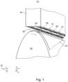
- the at least one nozzle bar 04 is arranged, for example, in at least one printing position, for example shown in Fig. 1 .
- the printing position describes the position of the nozzle bar 04 in which the nozzle bar 04 is arranged in a printing operating state of the printing machine.
- a respective print head 08 arranged in its printing position is preferably characterized in that the respective exit surface 09 has a distance from the intended transport path for at least one printing material 03 and/or from the at least one printing material 03 and/or from the printing material guide element 02 assigned to the respective nozzle bar 04, which distance is at most 5 mm (millimeters), preferably at most 1.5 mm and/or which is at least 0.5 mm, preferably at least 1.0 mm.
- At least one printing material 03 is guided along the transport direction T by means of the at least one printing material guide element 02 through a spatial region between the respective printing material guide element 02 and the relevant nozzle bar 04. Facing the printing material guide element 02, the at least one print head 08 is positioned with at least one exit surface 09 in the relevant nozzle bar 04.
- the at least one nozzle bar 04 preferably comprises at least one print head 08, in particular at least two print heads 08.
- the at least two print heads 08 are preferably arranged next to one another, in particular adjacent to one another.
- the at least two print heads 08 are arranged next to one another along the y-direction, in particular adjacent to one another, preferably adjacent, and/or preferably partially in the x-direction. overlapping.
- the individual print heads 08 of the relevant nozzle bar 04 are preferably arranged along the y-direction within at least one row, preferably within at least two, in particular parallel rows, of print heads 08.
- the respective exit surfaces 09 of at least two print heads 08 arranged next to one another, preferably adjacent, are positioned particularly within a row, each spaced apart from one another by the at least one positioning gap 07, in particular in the y-direction.
- the at least two print heads 08 arranged next to one another in the y-direction are arranged spaced apart from one another by the at least one positioning gap 07.
- the at least two print heads 08 arranged next to one another in the y-direction, in particular adjacent, in particular the respective exit surfaces 09 of the print heads 08 arranged next to one another in the y-direction delimit the corresponding positioning gap 07 in the y-direction. This makes it easier, for example, to position the respective print heads 08.
- the print heads 08 of the nozzle bar 04 which are preferably arranged in a row in the y-direction, for example in the x-direction, preferably in the transport direction T, are each arranged at least partially obliquely overlapping and/or the respective exit surfaces 09 of the corresponding print heads 08 are preferably arranged spaced apart from one another in the y-direction by the respective positioning gap 07.
- the nozzle bar 04 comprises, for example, at least two preferably parallel rows of print heads 08, wherein a row in the y-direction comprises at least two print heads 08, preferably a plurality of print heads 08.
- the print heads 08 of the rows arranged in the y-direction are preferably arranged offset from one another in the x-direction, whereby the respective exit surfaces 09 of the print heads 08 arranged offset from one another preferably overlap at least partially.
- the at least one printing unit 01 preferably has at least two nozzle bars 04, for example at least four nozzle bars 04.
- each nozzle bar 04 of the at least one printing unit 01 has a different printing fluid than the other nozzle bars 04, for example a different color.
- the printing machine has at least two printing units 01, each with at least one, preferably at least two, more preferably at least four, nozzle bars 04.
- at least eight different colors can thus be printed and/or the at least one printing material 03 can be printed on both the top and the bottom.
- at least one nozzle bar 04 of the nozzle bars 04 has cyan or magenta or yellow or black or at least one special color as the color of the printing fluid.
- the at least one nozzle bar 04 preferably has the at least one print head 08, preferably at least one inkjet print head 08 and/or at least one inkjet print head.
- the at least one print head 08 has the at least one exit surface 09 and at least one, in particular at least two contact surfaces 11.
- the at least one contact surface 11 is designed as a spacer surface 11.
- the contact surface 11 is preferably designed such that the at least one exit surface 09 is arranged to avoid unwanted contact with components or other bodies, for example when cleaning the at least one exit surface 09.
- the spacer surface 11 preferably extends over the entire extent of the respective print head 08. Dimensions over only a part of the extent of the respective print head 08 are also possible, however.
- the at least one exit surface 09 of the at least one print head 08 is a surface of the respective print head 08 which faces the transport path and is located in a plane whose normal vector is arranged parallel to the z-direction.
- the exit surface 09 is designed, for example, as a parallelogram, preferably as a non-rectangular parallelogram.
- a further embodiment of the exit surface 09 is a trapezoid, in particular an isosceles trapezoid.
- the exit surface 09 preferably comprises at least one opening, in particular a plurality of openings, through which the printing fluid can leave at least one volume, in particular a plurality of volumes, of the relevant print head 08, preferably in the form of drops.
- An exit direction of the at least one exit surface 09 is the direction in which the printing fluid, in particular in the form of drops, leaves and/or can leave the respective print head 08 through at least one opening of the corresponding exit surface 09.
- the exit direction of the exit surface 09 is preferably at least in one component and more preferably completely parallel to a surface normal of the exit surface 09 of the respective print head 08.
- the respective exit surfaces 09 of the relevant print heads 08 of a nozzle bar 04 which are arranged next to one another in the y-direction, are arranged at least partially adjacent to one another in the x-direction, more preferably at least partially overlapping.
- the sum of all exit surfaces 09 within at least one row arranged in the y-direction, for example also of at least two rows, of print heads 08 of a nozzle bar 04 extends over the entire working width of the respective nozzle bar 04.
- each position along a straight line in the y-direction on the transport path is assigned an opening within an exit surface 09 of the relevant nozzle bar 04, through which the printing fluid can leave a volume of a corresponding print head 08 of the nozzle bar 04.
- At least two print heads 08 are arranged in the y-direction each arranged next to one another, in particular adjacent to one another.
- two print heads 08 are arranged adjacent to one another.
- the respective exit surfaces 09 of the at least two print heads 08 are preferably each arranged spaced apart from one another by the one positioning gap 07.
- the at least one positioning gap 07 in the y-direction each has an extension of a maximum of 0.5 mm (zero point five millimeters), in particular a maximum of 0.2 mm.
- the at least one positioning gap 07 in the y-direction has an extension of at least 0.05 mm (zero point zero five millimeters), preferably of at least 0.1 mm.
- a longitudinal direction of the at least one positioning gap 07, preferably the positioning angle 46 of the longitudinal direction of the positioning gap 07, is preferably arranged in a plane spanned by the x-direction and the y-direction.
- the longitudinal direction of the at least one positioning gap 07 is preferably the direction in which the greatest extent of the at least one positioning gap 07 occurs.
- a cleaning direction G and/or the y-direction to a longitudinal direction of the positioning gap 07 in a positive mathematical direction of rotation, i.e. rotated counterclockwise preferably has a flat angle, in particular a positioning angle 46, of at least 50° (fifty degrees), preferably of at least 60° (sixty degrees), more preferably of at least 70° (seventy degrees) and/or of at most 130° (one hundred and thirty degrees), preferably of at most 120° (one hundred and twenty degrees), more preferably of at most 110° (one hundred and ten degrees).
- the longitudinal direction of the positioning gap 07 to the cleaning direction G preferably has a flat angle, in particular an opening angle 47, which is preferably acute-angled or obtuse-angled.
- the longitudinal direction of the positioning gap 07 preferably the positioning angle 46 of the longitudinal direction of the Positioning gap 07
- the longitudinal direction of the positioning gap 07 is arranged in the plane spanned by the x-direction and the y-direction.
- the longitudinal direction of the positioning gap 07 is the direction in which the greatest extent of the positioning gap 07 occurs.
- the longitudinal direction of the positioning gap 07 is oriented within the plane spanned by the x-direction and the y-direction with at least one component orthogonal to the cleaning direction G.
- the positioning angle 46 thus corresponds to the at least partial oblique overlap in the x-direction of at least two print heads 08 arranged next to one another, in particular adjacent to one another.
- the positioning angle 46 has an angle of not equal to 90°.
- at least one component of the longitudinal direction of the at least one positioning gap 07 preferably within the plane spanned by the x-direction and the y-direction, has a value greater than zero, wherein the component is oriented orthogonal to the y-direction and/or orthogonal to the cleaning direction G.
- the printing machine preferably has at least one control unit.
- the at least one control unit is preferably designed to control the at least one print head 08.
- the at least one control unit is preferably connected to the at least one print head 08 at least by means of lines.
- the at least one control unit is preferably designed to control the ejection of printing fluid through the at least one opening within the at least one nozzle surface 09.
- At least one feed device 13 for ejecting a fluid is assigned to the respective positioning gap 07.
- the at least one feed device 13 is designed as a nozzle 13, in particular as a cleaning nozzle 13.
- the feed device 13 is designed as a nozzle 13 for ejecting fluid, preferably a gaseous fluid and/or compressed gas.
- the feed device 13 is arranged so that a fluid, for example a compressed gas and/or a gas mixture, in particular air, and/or a liquid, can flow through the respective feed device 13 such that the fluid can leave the feed device 13, in particular through an outlet opening 17, in an outlet direction L.
- At least one component of the outlet direction L is directed towards the respective positioning gap 07.
- at least one feed device 13 for ejecting a fluid with an outlet direction L is assigned to the respective positioning gap 07, wherein at least one component of the outlet direction L is directed towards the respective positioning gap 07.
- the outlet opening 17 of the feed device 13 is directed towards the positioning gap 07, for example from above and/or from above the printing material guide element 02 in the direction of the printing material guide element 02.
- the feed device 13 preferably comprises at least one feed element 14 and/or at least one outlet element 16; 43, wherein the at least one outlet element 16; 43 is preferably designed as at least one limiting element 16 and/or at least one opening element 43, and/or the at least one outlet opening 17.
- the feed device 13 preferably has at least one cavity, which is preferably connected to the at least one outlet opening 17.
- the at least one outlet element 16; 43 is designed as at least one sheet or a tube.
- the limiting element 16 is preferably designed to be flat, for example as a flat sheet.
- the at least one opening element 43 preferably comprises at least one recess 17, which is more preferably designed as the at least one outlet opening 17.
- the at least one feed device 13 is preferably connected to at least one print head 08 of the respective print heads 08 which delimit the respective positioning gap 07. Additionally or alternatively, the at least one nozzle bar 04 preferably comprises the at least one Feed device 13, wherein the feed device 13 is preferably positioned in the z-direction on the side of the exit surface 09 which faces away from the at least one opening of the respective exit surface 09.
- the at least one nozzle bar 04 preferably comprises the at least one feed device 13, wherein the feed device 13 is preferably arranged in the z-direction on the side of at least one exit surface 09 of at least one print head 08 of the corresponding nozzle bar 04 facing away from the transport path and/or wherein the respective outlet direction L of the at least one feed device 13 is directed towards at least one positioning gap 07 between two print heads 08 which are preferably adjacent in the y-direction.
- the at least one feed device 13 is arranged in the z-direction on the side of the respective exit surface 09 facing away from the transport path. Further preferably, the at least one feed device 13 is positioned on that side of the print head 08, in particular the exit surface 09, on which the print head 08 is attached to the corresponding nozzle bar 04. Further preferably, the at least one feed device 13 is positioned such that the outlet direction L is directed from one side of the print head 08, in particular one side of the exit surface 09, to the at least one positioning gap 07 on which the print head 08 is attached to the corresponding nozzle bar 04.
- the feed device 13 is arranged at a distance from the positioning gap 07 in the z-direction. Further preferably, the feed device 13 is arranged adjacent to the positioning gap 07 in the z-direction.
- the outlet opening 17 is arranged at a distance from the positioning gap 07 in the z-direction. Further preferably, the outlet opening 17 is arranged adjacent to the positioning gap 07 in the z-direction.
- the feed device 13, in particular the respective outlet opening 17, is preferably arranged at a distance in the z-direction from the respective exit surfaces 09 of two print heads 08, which in the y-direction are arranged next to each other and whose exit surfaces 09 limit the corresponding positioning gap 07.
- the outlet direction L is preferably a direction in which a fluid, for example a gas and/or a gas mixture, in particular air, and/or a liquid, can leave the relevant feed device 13, preferably through the at least one outlet element 16; 43, in particular the at least one outlet opening 17.
- the outlet direction L is parallel in at least one component and/or points in an identical direction to the exit direction of the at least one exit surface 09 of a print head 08 of the nozzle bar 04.
- at least one component of the outlet direction L is parallel and/or points in an identical direction to the surface normal of the exit surface 09 of the respective print head 08 and/or a direction in which the printing fluid can leave the respective exit surface 09.
- the outlet direction L is preferably parallel to a main direction, which is preferably defined by at least one side wall of the feed device 13, which is further preferably defined by the at least one limiting element 16.
- the outlet direction L preferably has at least one component in the z-direction, wherein the component in the z-direction preferably faces the transport path.
- the outlet direction L comprises at least one component in the z-direction and at least one component in the x-direction, wherein the component in the z-direction is larger than the component in the x-direction.
- the outlet direction L is preferably a direction within a plane which is aligned with the position of the positioning gap 07, for example along the y-direction displaced by the z-direction and at least one direction of a shortest boundary which is spanned in a plane of the x-direction and y-direction, of the respective outlet surface 09 of the relevant print head 08, which preferably defines the positioning gap 07. limited, spanned.
- the at least one feed device 13 has an extension in the y-direction which is identical to the extension of the respective positioning gap 07 in the y-direction. More preferably, the at least one feed device 13 has an extension in the y-direction of a maximum of 0.5 mm (millimeters), in particular a maximum of 0.2 mm. More preferably, the at least one feed device 13 has an extension in the y-direction of at least 0.05 mm, preferably of at least 0.1 mm.
- the outlet opening 17 is designed in the plane which is spanned by the z-direction and at least one direction of the shortest boundary, which is spanned in a plane of the x-direction and y-direction, of the respective exit surface 09 of the relevant print head 08, wherein the respective exit surface 09 delimits the positioning gap 07, such that the relevant outlet opening 17 has a smaller dimension in the z-direction far from the respective exit surface 09, in particular far from the transport path, than in the z-direction close to the exit surface 09, in particular close to the transport path.
- the outlet opening 17 in the plane which is spanned to the position of the positioning gap 07, for example along the y-direction, shifted by the z-direction and at least one direction of the shortest boundary, which is spanned in a plane of the x-direction and y-direction, of the respective outlet surface 09 of the relevant print head 08, which delimits the positioning gap 07 has a shape which corresponds, for example, to a two-dimensional longitudinal section of a cone.
- the diameter of the outlet opening 17, measured in the direction of the shortest boundary, which is spanned in a plane of the x-direction and y-direction, of the outlet surface 09, which delimits the positioning gap 07 preferably increases along the z-direction in the direction of the transport path.
- the at least one outlet opening 17 at the point of the feed device 13 which is the smallest distance from the respective positioning gap 07 has a maximum diameter.
- the maximum diameter of the corresponding outlet opening 17 is greater than the extent of the at least one exit surface 09 of the relevant print head 08, which is arranged at the corresponding positioning gap 07, in the direction of the shortest boundary of the respective exit surface 09.
- the limiting element 16 preferably limits the respective outlet opening 17 in the y-direction, preferably on one side.
- the respective limiting element 16 is in direct contact with the respective opening element 43.
- the feed element 14 is in direct contact with the respective opening element 43, so that there is preferably a connection between at least one cavity of the feed element 14 and the respective outlet opening 17.
- the opening element 43 and in particular the respective outlet opening 17 of the corresponding feed device 13 is arranged between the respective limiting element 16 and the respective feed element 14.
- the supply element 14 preferably comprises the at least one cavity, wherein the cavity is connected to at least one source for supplying the at least one fluid, for example a gas and/or a gas mixture, in particular air, and/or a liquid, and to the outlet opening 17.
- at least one source for supplying the at least one fluid, for example a gas and/or a gas mixture, in particular air, and/or a liquid.
- a fluid for example a gas and/or gas mixture and/or a liquid
- the at least one fluid in particular compressed gas, flows through the cavity of the supply element 14 and preferably hits the limiting element 16 through the recess 17 of the opening element 43.
- the fluid for example the gas and/or the gas mixture and/or the liquid, is deflected, for example, such that the fluid preferably flows through the at least one outlet opening 17 from the respective supply device 13 into
- the fluid for example the gas and/or the gas mixture and/or the liquid, has a pressure of at least 0.1 bar, in particular of at least 0.2 bar, and at most 0.7 bar, in particular of at most 0.5 bar, when exiting the feed device 13.
- a pressure of at least 0.1 bar in particular of at least 0.2 bar
- at most 0.7 bar in particular of at most 0.5 bar
- An exit of the fluid in the exit direction L is indicated by dashed lines as an example.
- the nozzle bar 04 comprises at least one positioning guide 06, which is preferably arranged so as to be movable, in particular linearly movable.
- the respective nozzle bar 04 in particular the respective print heads 08 of the nozzle bar 04, can preferably be arranged and/or positioned optionally in the at least one printing position and/or at least one rest position and/or at least one maintenance position by the respective positioning guide 06.
- the at least one positioning guide 06 is preferably designed to arrange the at least one nozzle bar 04 in its at least one position, preferably in at least one printing position and/or in at least one maintenance position and/or in at least one rest position.
- the at least one control unit is preferably designed to control the at least one positioning guide 06.
- the at least one control unit is preferably connected to the at least one positioning guide 06, preferably to at least one drive of the at least one positioning guide 06, at least by means of cables.
- the at least one nozzle bar 04 is designed to be movable and/or movable by a movement in a direction which has a larger or maximum component in the vertical direction or the z-direction and a smaller or minimum component in the horizontal direction, from the at least one printing position to the at least one rest position or to the at least one maintenance position and/or from the at least one rest position to the at least one printing position or to the at least one maintenance position and/or from the at least one maintenance position to the at least one printing position or to the at least one rest position.
- the at least one nozzle bar 04 preferably has the at least one printing position in which the at least one nozzle bar 04 is preferably arranged in a printing operating state.
- the at least one nozzle bar 04 preferably the at least one nozzle surface 09, preferably has a distance from the transport path of printing material 03 that is at most 5 mm (five millimeters), preferably at most 1.5 mm (one point five millimeters) and/or that is at least 0.5 mm (zero point five millimeters), preferably at least 1.0 mm (one point zero millimeters).
- the distance of the respective exit surface 09 of a print head 08 arranged in a maintenance position from the intended transport path for at least one printing material 03 and/or from the at least one printing material 03 and/or from the printing material guide element 02 assigned to the respective nozzle bar 04 is greater than in the corresponding printing position.
- the rest position is preferably a position in which the at least one print head 08 is removed from the printing machine and/or the at least one printing unit 01 and/or the at least one nozzle bar 04 and/or inserted into the printing machine and/or the at least one printing unit 01 and/or the at least one nozzle bar 04 can be used.
- an operator in the resting position, preferably has more space available to access the at least one print head 08, while in the maintenance position, there is preferably only sufficient space available to be able to carry out internal, in particular automatic, processes within the printing machine, for example cleaning at least one exit surface 09 of at least one print head 08.
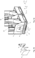
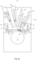
- Fig. 4a shows, for example, a schematic representation of at least one printing unit 01 with several nozzle bars 04, wherein at least one nozzle bar 04 is arranged in the printing position and at least one nozzle bar 04 is arranged in the rest position.
- Fig. 4b shows, for example, a schematic representation of a printing unit 01 with several nozzle bars 04 according to Fig. 4a , wherein at least one nozzle bar 04 is arranged in a maintenance position.
- the printing press has at least one cleaning device 18.
- the at least one printing unit 01 preferably comprises the at least one cleaning device 18.
- each nozzle bar 04 of a printing unit 01 is assigned at least one cleaning device 18.
- the at least one print head 08 of a nozzle bar 04 arranged in the maintenance position is assigned a cleaning device 18 which is positioned in a cleaning position via a guide system 19.
- the at least one cleaning device 18 is provided for cleaning the at least one exit surface 09 and/or the at least one contact surface 11 of the at least one print head 08 of a corresponding nozzle bar 04.
- the at least one cleaning device 18 cleans the at least one positioning gap 07.
- the at least one cleaning device 18 is designed to clean the at least one nozzle surface 09 and the at least one contact surface 11.
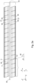
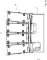
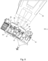
- Fig. 5a shows an example of a corresponding cleaning device 18 in the cleaning position, which is preferably assigned to a nozzle bar 04 in the maintenance position. For the sake of clarity, only four print heads 08 of the nozzle bar 04 in question are shown.
- the cleaning position of the at least one cleaning device 18 preferably corresponds to a position in which the cleaning device 18 is in direct or indirect contact with at least one print head 08 of the relevant nozzle bar 04, in particular one to be cleaned, and/or preferably a position in which the cleaning device 18 is arranged to carry out the cleaning of the at least one print head 08 of the relevant nozzle bar 04.
- the at least one cleaning device 18 preferably has at least one guide system 19.
- the at least one cleaning device 18 can preferably be moved, in particular as a whole, at least orthogonally to the transverse direction A, preferably via at least one guide system 19.
- at least one cleaning device 18 is and/or can be assigned to at least one exit surface 09 of at least one print head 08, in particular to one exit surface 09 of at least two, preferably at least three and more preferably at least four print heads 08.
- a printing unit 01 comprises at least one cleaning device 18 per nozzle bar 04.
- At least two cleaning devices 18 are connected to a preferably common guide system 19 and/or are designed to be movable and/or moving by the preferably common guide system 19.
- the at least one guide system 19 preferably has at least one guide element, for example designed as a beam and/or rod and/or rail and/or linear guide.
- the at least one cleaning device 18 is designed to move and/or be movable along the at least one guide element and/or is moved, preferably moved in a straight line.
- the at least one cleaning device 18 is preferably arranged to be linearly movable and/or moving via the at least one guide system 19, preferably by means of at least one cleaning drive.
- the at least one cleaning device 18 is moved along a guide path of the at least one guide element.
- the guide path along the at least one guide element is arranged in a plane whose normal vector corresponds to the transverse direction A and/or the y-direction.
- the guide path has a larger component in the horizontal direction and a smaller component in the vertical direction, more preferably the guide path is horizontal.
- the at least one cleaning device 18 preferably has at least one storage position and at least one use position.
- the at least one cleaning device 18 is moved along the at least one guide element from the at least one storage position to the at least one use position and/or vice versa.
- the at least one storage position of the at least one cleaning device 18 is preferably a position in which the at least one cleaning device 18 is arranged outside the area between the at least one nozzle bar 04 and the transport path of the at least one printing material 03, for example defined by the at least one printing material guide element 02 opposite the at least one nozzle bar 04.
- the at least one cleaning device 18 is preferably arranged in the at least one storage position in the x direction before or after the at least one nozzle bar 04.
- the at least one use position of the at least one cleaning device 18 is preferably a position in which the at least one cleaning device 18 is arranged within the area between the at least one nozzle bar 04 and the transport path of the at least one printing material 03, for example defined by the at least one printing material guide element 02 opposite the at least one nozzle bar 04.
- the at least one cleaning device 18 is arranged in the at least one use position during cleaning of the at least one print head 08.
- the at least one printing unit 01 preferably has the at least two nozzle bars 04.
- the at least one printing unit 01 then preferably has at least two cleaning devices 18.
- one cleaning device 18 of the at least two cleaning devices 18 is assigned to a nozzle bar 04 of the at least two nozzle bars 04.
- the at least two cleaning devices 18 have the at least one guide system 19, which is preferably designed as a common guide system 19.
- the at least two cleaning devices 18 are moved together along the at least one guide element of the at least one common guide system 19 from their at least one use position to their at least one storage position and/or vice versa.
- the cleaning device 18 assigned to the corresponding nozzle bar 04 is preferably designed as at least one locking element, for example in the form of at least one maintenance stop.
- the nozzle bar 04 having the corresponding print head 08 is preferably pulled and/or pressed against the cleaning device 18 in its maintenance position by applying a force and/or, for example, by gravity.
- the maintenance position of the at least one nozzle bar 04 is preferably clearly defined.
- the at least one cleaning device 18 preferably comprises at least one cleaning guide 44 and/or at least one cleaning drive 21 and/or at least one collecting tray 22 and/or at least one support device 23; 24 and/or at least one cleaning unit 26, preferably at least one cleaning unit 26 per row of print heads 08 in the y-direction of the relevant nozzle bar 04.
- the at least one cleaning device 18 is preferably connected via at least one guide system 19, preferably by means of the cleaning drive 21 preferably arranged to be linearly movable.
- the at least one support device 23; 24 is preferably designed as at least one positioning aid 23 and/or as at least one cleaning aid 24.
- the at least one cleaning device 18 preferably has an extension in the transverse direction A that is at least as large as the working width of the at least one nozzle bar 04 in the transverse direction A.
- the at least one cleaning device 18 preferably has an extension in the transport direction T of the printing material 03 that is at least as large as the working width of the at least one nozzle bar 04 in the transport direction T.
- all exit surfaces 09 of all print heads 08 of the at least one nozzle bar 04 can preferably be cleaned in one process.
- the at least one cleaning device 18 has an extension in the transport direction T that is at least as large as all working widths of all nozzle bars 04 of the printing unit 01 in the transport direction T taken together. As a result, all exit surfaces 09 of all print heads 08 of the at least one printing unit 01 can then be cleaned in one process.
- the at least one cleaning unit 26, preferably the at least one cleaning element 31, is preferably arranged to be movable along the cleaning guide 44, for example by means of the cleaning drive 21, and/or is moved along the cleaning guide 44. More preferably, the at least one cleaning unit 26 is arranged to be movable in and/or against a cleaning direction G and/or is moved.
- the at least one collecting tray 22 is preferably arranged to at least partially enclose the at least one cleaning unit 26. More preferably, the collecting tray 22 is arranged such that the collecting tray 22 at least partially encloses the cleaning unit 26 and the at least one print head 08 of the relevant nozzle bar 04 arranged in the maintenance position.
- the at least one cleaning device 18 preferably has at least one cleaning guide 44.
- the at least one cleaning guide 44 is preferably arranged along the longitudinal direction of the at least one cross member 22, for example within the at least one cross member 22.
- the at least one cleaning element 31 is preferably movable and/or arranged to move along the longitudinal direction of the at least one cross member 22 and/or preferably along the at least one cleaning guide 44, for example driven by at least one cleaning drive.
- the at least one cleaning drive is preferably controlled by the at least one control unit of the printing press.
- the at least one cleaning element 31 is preferably arranged to be movable in and/or against the cleaning direction G and/or is moved.
- the cleaning direction G is the direction in which an element cleaning the at least one print head 08, in particular the at least one cleaning element 31, passes this at least one print head 08.
- the cleaning direction G is a direction G in which the at least one cleaning element 31 of the at least one cleaning device 18 is arranged to be movable and/or is designed to move in order to carry out a cleaning step.
- the cleaning direction G is preferably horizontal.
- the cleaning direction G preferably has at least one component that is arranged parallel to the transverse direction A and/or parallel to the y-direction and is preferably oriented opposite to the y-direction. More preferably, the cleaning direction G is arranged parallel to the transverse direction A and/or parallel to the y-direction and is preferably oriented opposite to the y-direction.
- the cleaning direction G is preferably oriented orthogonally to at least one transport direction T provided for transporting at least one printing material 03 and/or orthogonally to the x-direction.
- the at least one cleaning unit 26 and more preferably at least one cleaning element 31 are arranged to be movable in and/or against the cleaning direction G.
- the cleaning device 18 has the at least one cleaning element 31.
- the at least one cleaning unit 26 preferably comprises at least one mounting element 28, preferably at least two mounting elements 28, and/or at least one force element 29 and/or at least one carrier 27 and/or the at least one cleaning element 31.
- the at least one mounting element 28, preferably at least two mounting elements 28, and/or the at least one force element 29 and/or the at least one carrier 27 and/or the at least one cleaning element 31 are preferably firmly connected to one another within the corresponding cleaning unit 26.
- the at least one mounting element 28, in particular the at least two mounting elements 28, are preferably in direct contact with the at least one force element 29.
- the at least one force element 29 is designed, for example, as a bellows and/or hollow body and/or spring and is preferably adjustable with regard to its extension and/or dimension in the z direction, preferably in a direction whose main component corresponds to the z direction.
- the at least one carrier 27 is preferably designed as a base body and/or preferably carries the at least one mounting element 28, preferably at least two mounting elements 28, and/or the at least one force element 29 and/or the at least one cleaning element 31 of the corresponding cleaning unit 26.
- the at least one cleaning element 31 is preferably arranged in direct contact with at least one mounting element 28.
- the extension and/or dimension of the cleaning unit 26 in the z-direction is adjustable by changing the extension and/or dimension of the at least one force element 29 of the relevant cleaning unit 26. and/or changeable and/or movable. Due to this mobility, the at least one cleaning element 31 can preferably be brought into contact with other components and/or brought out of contact, with such components being in particular the at least one print head 08 and/or the at least one support device 23; 24.
- the at least one cleaning unit 26 comprises the at least one cleaning element 31, which is connected to the at least one carrier 27 via the at least one force element 29, preferably via at least four force elements 29, for example via exactly four force elements 29.
- the at least one force element 29, in particular the at least four force elements 29, are each designed as a spring.
- the at least one cleaning element 31 is preferably mounted and/or fastened in a floating manner in the at least one carrier 27, which is preferably designed as a base body, by the at least one force element 29.
- the cleaning device 18 has at least one positioning aid 23 that is different from each print head 08, which preferably has at least one contact surface that is oriented in the same direction as the at least one contact surface 11 and/or exit surface 09 of the at least one print head 08.
- the at least one contact surface of the positioning aid 23 is preferably located with respect to the cleaning direction G in connection with or at a distance from the at least one contact surface 11 of a respective print head 08.
- the contact surface of the positioning aid 23 has an identical component in the z-direction as the exit surface 09 of a print head 08 to be connected to the corresponding cleaning element 31. cleaning print head 08.
- the contact surface of the positioning aid 23 is oriented in the same direction as the at least one exit surface 09.
- the cleaning element 31 is preferably designed as a contact element, for example as a wiper.
- the contact surface of the positioning aid 23 is oriented in the same direction as the at least one contact surface 11, in particular the at least one spacing surface 11.
- the at least one positioning aid 23 is arranged such that the at least one cleaning element 31 is arranged so that it can be clearly positioned relative to at least one print head 08 that is to be cleaned in particular.
- the cleaning device 18 preferably comprises at least one cleaning aid 24.
- the cleaning aid 24 is preferably designed such that the at least one cleaning element 31 can be cleaned.
- the cleaning aid 24 preferably has at least one spray device and/or at least one wiping device.
- the at least one cleaning device 18 has at least one sealing element 56, for example at least one sealing lip.
- the at least one sealing element 56 is arranged within at least one cross member 22 of the at least one cleaning device 18.
- the at least one cleaning device 18 is in the at least one use position during sealing of the at least one nozzle surface 09 of the at least one print head 08 with the at least one sealing element 56, i.e. during direct contact between the at least one sealing element 56 and the at least one print head 08. arranged.
- the at least one nozzle bar 04 and the at least one cleaning device 18 are moved relative to one another, preferably the at least one nozzle bar 04 is lowered onto the at least one cleaning device 18, for example from the at least one maintenance position.
- the at least one sealing element 56 forms with the at least one print head 08 and at least one limiting unit, for example designed as a support 57, in the case of direct contact between the at least one print head 08 and the at least one sealing element 56 an at least partially closed spatial area, preferably designed as a preservation area.
- the preservation area preferably contains an atmosphere which has at least one preservation medium.
- the at least one preservation medium preferably has air enriched with at least water and/or air enriched with pressurized fluid.
- the preservation area is rinsed and/or flooded with at least one fluid, for example with air and/or with air enriched with water, for example, and/or with cleaning agent and/or with pressurized fluid.
- This atmosphere is preferably designed to protect the at least one nozzle surface 09 and protects the printing fluid of the at least one print head 08 from drying out.
- the at least one sealing element 56 is designed to seal all of the print heads 08 of the at least one row of print heads 08 together. For example, the at least one print head 08 is lowered onto the at least one sealing element 56.
- the at least one cleaning device 18 has the at least one cleaning element 31.
- the at least one cleaning element 31 is designed to clean the at least one nozzle surface 09.
- the nozzles of the nozzle surface 09 are thus cleaned so that no blockage and/or no change in the cross section of the respective nozzle occurs, for example due to dried pressure fluid and/or dirt.
- the at least one cleaning element 31 is designed to clean the at least one contact surface 11. formed. Dirt and/or printing fluid is thus advantageously removed from the at least one contact surface 11. Substances that hinder the guidance of the at least one cleaning element 31 along the cleaning direction G, in particular printing fluid and/or dirt, are advantageously removed.
- printing fluid and/or dirt can get from the at least one contact surface 11 to the at least one nozzle surface 09, for example due to the movement of the at least one cleaning element 31 and/or due to air turbulence and/or other external influences.
- Printing fluid and/or dirt remaining on the at least one contact surface 11 can also be transferred uncontrollably to a printing substrate 03 during printing.
- the at least one cleaning element 31 is designed to clean the at least one positioning gap 07.
- printing fluid and/or dirt can get from the at least one positioning gap 07 onto the at least one nozzle surface 09 or can escape from the positioning gap 07 in an uncontrolled manner during printing operation, for example due to the movement of the at least one cleaning element 31 and/or due to air turbulence and/or other external influences.
- cleaning the at least one positioning gap 07 these risks are advantageously removed before the at least one print head 08 is damaged and/or the quality of the print image produced is deteriorated.
- the at least one cleaning element 31 is preferably designed as a cleaning head 31.
- the cleaning element 31 is preferably firmly connected to the at least one mounting element 28 and/or the at least one carrier 27 of the relevant cleaning device 18, in particular the relevant cleaning unit 26.
- the at least one cleaning element 31 is preferably arranged to be movable in and/or against the cleaning direction G.
- the at least one Cleaning element 31 is designed to clean all nozzle surfaces 09 and/or contact surfaces 11 and/or positioning gaps 07 of the at least two print heads 08, which are arranged in the at least one row.
- the at least one cleaning element 31 is movable and/or is moved in the cleaning direction G and/or against the cleaning direction G for cleaning.
- At least one cleaning agent and/or cleaning fluid preferably refers to a liquid which is used to clean individual components of the printing press, preferably to clean the at least one nozzle surface 09 of the at least one print head 08.
- the cleaning agent is preferably used to remove contaminants such as dried coating agents such as printing ink or ink and/or parts of a printing material such as paper fibers and/or dust and/or the like and/or mixtures of the substances mentioned.
- the at least one cleaning agent comprises water and/or at least one surfactant and/or at least one solvent.
- the at least one cleaning agent comprises printing fluid, which preferably does not contain any pigments.
- the at least one cleaning fluid is preferably designed to at least partially dissolve the printing fluid of the at least one nozzle bar 04.
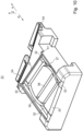
- the at least one cleaning element 31 has at least one sliding surface 32.
- the at least one sliding surface 32 has a greater extent in the cleaning direction G than orthogonal to the cleaning direction G.
- the at least one sliding surface 32 is designed for direct contact with the at least one print head 08.
- the at least one cleaning element 31 is designed to come into direct contact with the at least one contact surface 11 of the at least one print head 08 by means of the at least one sliding surface 32 when the latter is arranged in a cleaning position.
- the at least one sliding surface 32 When the at least one cleaning element 31 is placed against the at least one print head 08 or vice versa and/or When the at least one cleaning element 31 is moved in or against the cleaning direction G, the at least one sliding surface 32, preferably all sliding surfaces 32, are designed to come into contact, in particular direct contact, with the at least one contact surface 11.
- the at least one sliding surface 32 is additionally arranged orthogonally to the cleaning direction G in front of or behind the at least one nozzle surface 09, i.e. preferably arranged laterally.
- the surface of the at least one sliding surface 32 is arranged in a plane.
- the plane is preferably spanned by the x-direction and the y-direction.
- the plane is preferably arranged parallel to a plane of the surface of the at least one contact surface 11 of the at least one print head 08, in particular when the at least one cleaning element 31 is positioned against the at least one print head 08.
- the cleaning element 31 has a higher coordinate in the z-direction in the region of the at least one sliding surface 32 than in the region of the at least one cleaning region 37, preferably at least in the region of the at least one fluid supply 38, in particular its boundary 71.
- the boundary 71 of the at least one fluid supply 71 is preferably at a distance in the z-direction from the surface of the at least one sliding surface 32.
- the at least one nozzle surface 09 is advantageously protected from direct contact with the cleaning element 31. This advantageously ensures that the at least one nozzle surface 09 is not damaged by the at least one cleaning region 37, in particular the at least one fluid supply 38.
- the at least one cleaning element 31 has at least two sliding surfaces 32.
- the at least one cleaning element 31 has at least two sliding surfaces 32, which are arranged orthogonally to the cleaning direction G one behind the other, i.e. next to one another in the cleaning direction G.
- the at least two sliding surfaces 32 arranged one behind the other orthogonally to the cleaning direction G are arranged at a distance from one another through the at least one cleaning region 37.
- the at least two sliding surfaces 32 arranged one behind the other orthogonally to the cleaning direction G are preferably spaced apart from one another by a distance which corresponds to the distance between two contact surfaces 11 of the at least one print head 08 arranged one behind the other orthogonally to the cleaning direction G.
- the at least two sliding surfaces 32 of the cleaning element 31, which are arranged next to one another in the cleaning direction G, are preferably at the same distance from one another as two contact surfaces 11 of a print head 08 spaced apart from one another in the x direction.
- the at least two sliding surfaces 32 of the cleaning element 31, which are arranged next to one another in the cleaning direction G, are preferably spaced apart at least as far as the length of a nozzle surface 09 in the x direction. This advantageously ensures that the at least one nozzle surface 09 does not come into direct contact with at least one of the sliding surfaces 32 and is not damaged by this.
- the distance between the at least two sliding surfaces 32 arranged one behind the other orthogonally to the cleaning direction G is less than 50 mm (fifty millimeters), preferably less than 45 mm (forty-five millimeters), more preferably less than 40 mm (forty millimeters), more preferably less than 38 mm (thirty-eight millimeters).
- the at least two sliding surfaces 32 arranged next to one another in the cleaning direction G prevent the at least one cleaning element 31 from tipping sideways and/or jamming and/or these sliding surfaces 32 stabilize the at least one cleaning element 31 in the direction orthogonal to the cleaning direction G.
- the at least one sliding surface 32 When the at least one cleaning element 31 is placed against the at least one print head 08 or vice versa and/or when the cleaning element 31 is moved in or against the cleaning direction G, the at least one sliding surface 32, preferably all sliding surfaces 32, are preferably arranged orthogonally to the cleaning direction G in front of or behind the at least one exit surface 09, for example spaced apart from the at least one exit surface 09 orthogonally to the cleaning direction G. So preferably arranged laterally.
- the at least one cleaning element 31 has the at least two sliding surfaces 32, which are arranged one behind the other in the cleaning direction G.
- the at least two sliding surfaces 32 which are arranged one behind the other in the cleaning direction G, are spaced apart from one another by a distance greater than zero.
- the at least one sliding surface 32 has a greater extent in the cleaning direction G than orthogonal to the cleaning direction G.
- these at least two sliding surfaces 32 are arranged in alignment with one another in relation to the cleaning direction G.
- the at least two sliding surfaces 32 arranged one behind the other in the cleaning direction G prevent the at least one cleaning element 31 from tipping and/or jamming in the cleaning direction G and/or these sliding surfaces 32 stabilize the at least one cleaning element 31 in the cleaning direction G.
- the points on the surface of the at least one cleaning element 31 which are arranged counter to the cleaning direction G after the at least one second fluid discharge 41 are preferably at a distance, preferably greater than zero, from the plane of the surface of the at least one sliding surface 32.
- the at least one cleaning element 31 preferably has the at least one sliding surface 32, preferably the at least two sliding surfaces 32, counter to the cleaning direction G only, preferably exclusively, in front of the at least one second fluid discharge 41.
- the at least one sliding surface 32 is preferably designed to come into direct contact with the at least one contact surface 11 only in front of the at least one second fluid discharge 41, counter to the cleaning direction G.
- no part of the at least one sliding surface 32, preferably of the at least two sliding surfaces 32, and/or no further sliding surface 32 is arranged counter to the cleaning direction G after the at least one second fluid discharge 41.
- the points on the surface of the at least one cleaning element 31 which are counter to the cleaning direction G after the at least one second fluid discharge 41 are arranged, in the z-direction below the plane of the surface of the at least one sliding surface 32.
- the at least one cleaning element 31 is preferably designed to come into direct contact with the at least one contact surface 11 of the at least one print head 08 by means of the at least one sliding surface 32 when the latter is arranged in a cleaning position.
- the at least one sliding surface 32 is designed to come into direct contact with the at least one contact surface 11 against the cleaning direction G only before the at least one second fluid discharge 41.
- the at least one cleaning device 18 is designed to clean the at least two rows of print heads 08 of the at least one nozzle bar 04, preferably simultaneously and/or in parallel.
- the at least one cleaning element 31 is designed to clean the at least two rows of print heads 08 or there are at least two cleaning elements 31, each of which cleans at least one row of the at least two rows of print heads 08.
- the at least one nozzle bar 04 is preferably arranged in the at least one maintenance position.
- the at least one cleaning device 18 is preferably arranged in the at least one use position.
- the cleaning head 31 is arranged in direct or indirect contact with the at least one print head 08, then at least one cleaning fluid, in particular a cleaning agent, can be dispensed from the at least one fluid supply 38 in the immediate vicinity of the exit surface 09 of the at least one print head 08 and/or a positioning gap 07 and through the at least one Fluid discharge opening 39; 41 is also sucked out again in the immediate vicinity of the exit surface 09 of the at least one print head 08 and/or a positioning gap 07.
- at least one cleaning fluid in particular a cleaning agent
- the cleaning head 31 is preferably brought so close to the at least one print head 08 that a cleaning gap is formed between the cleaning head 31 on the one hand and the exit surface 09 of the print head 08 on the other hand, through which the fluid, in particular the cleaning liquid, flows and as a result the exit surface 09 of the at least one print head 08 and/or a positioning gap 07 is cleaned and/or can be cleaned.
- the cleaning head 31 preferably has the at least one cleaning area 37.
- the at least one cleaning area 37 preferably has the at least one fluid supply 38 and the at least one fluid discharge opening 39; 41. More preferably, the cleaning area 37 has the at least one fluid supply 38 and/or the at least one fluid discharge 39 and/or the at least one fluid suction 41.
- the at least one fluid discharge opening 39; 41 is preferably connected to at least one sink for discharging, for example, cleaning agent and/or dirt and/or particles.
- the at least one fluid supply 38 is preferably connected to a source of cleaning agent.
- the fluid supply 38 is preferably designed as a fluid supply opening 38 within the cleaning area 37.
- the at least one cleaning area 37 is preferably, in a plan view of the cleaning element 31, that area of the surface of the at least one cleaning element 31 which comprises the at least one fluid supply 38 and the at least one fluid discharge opening 39; 41.
- the components of the at least one cleaning area 37 have a distance of greater than zero to the at least one print head 08, in particular to its nozzle surface 09 and/or to its at least one contact surface 11, when the at least one cleaning element 08 is positioned against the at least one print head 08.
- the surface of the at least one cleaning area 37 is at a distance of greater than zero to the at least one print head 08, in particular to its nozzle surface 09 and/or to its at least one contact surface 11, preferably permanently spaced apart.
- the components of the at least one cleaning region 37 are designed to come into indirect contact with the at least one print head 08, in particular with its nozzle surface 09 and/or with its at least one contact surface 11, during the cleaning process.
- the at least one cleaning head 31 preferably has at least one ramp 33; 34. More preferably, the cleaning head 31 has at least one first ramp 33 and at least one second ramp 34.
- the at least one cleaning element 31 can be arranged in at least one first position and/or in at least one second position, wherein the first position of the cleaning element 31 is arranged at a distance from the second position of the cleaning element 31, preferably along the cleaning direction G.
- the at least one print head 08 and/or the at least one cleaning head 31 has at least one guide device 36.
- This guide device 36 is preferably designed as a guide surface 36, the surface normal of which has at least one component that is orthogonal to the z-direction and to the cleaning direction G.
- the at least one guide device 36 is preferably arranged such that the cleaning head 31 can be positioned and/or is positioned in a tolerance range or an exact position with respect to a direction oriented parallel to the x-direction and/or orthogonal to the cleaning direction G and orthogonal to the z-direction.
- the at least one guide surface 36 of a cleaning head 31 preferably borders directly on at least one sliding surface 32 of the respective cleaning head 31.
- the at least one sliding surface 32 is spaced from the at least one guide surface 36, preferably with at least one further surface in between.
- the at least one further surface is parallel to the at least one sliding surface 32.
- the at least one further surface is preferably spaced from the plane of the surface of the at least one sliding surface 32, for example arranged below in the z-direction, preferably by at least 0.1 mm (zero point one millimeter) and/or by a maximum of 0.2 mm (zero point two millimeters) to the plane of the surface of the at least one sliding surface 32.
- At least one ramp 33 is arranged opposite to the cleaning direction G in front of the at least one cleaning area 37, preferably in front of the at least one fluid supply 38 and/or in front of the at least one fluid discharge 39; 41.
- the at least one first ramp 33 is preferably a first part of the surface of the cleaning element 31 that comes into view.
- the at least one first ramp 33 is designed as an entrance ramp 33.
- the first ramp 33 has a positive gradient starting from an outer point of the at least one cleaning element 31 to its at least one cleaning area 37.
- the first ramp 33 is preferably arranged to reduce the distance between a reference point of the at least one print head 08 to be cleaned and the surface of the at least one cleaning element 31 facing it, in particular when the at least one cleaning element 31 moves in the cleaning direction G.
- the first ramp 33 preferably has a positive gradient starting from an outer point of the at least one cleaning element 31 to its at least one cleaning area 37.
- the reference point of the first ramp 33 is preferably a point on the first ramp 33 which is arranged perpendicular to the print head 08 to be cleaned.
- the first ramp 33 In the first position of the cleaning element 31, the first ramp 33 preferably has a first distance from the print head 08 to be cleaned, preferably from at least one exit surface 09 and/or spacing surface 11 to be cleaned, at the reference point of the first ramp 33.
- the first ramp 33 in the second position of the cleaning element 31 at the reference point of the first ramp 33 has a second distance to a print head 08 to be cleaned, preferably to at least one exit surface 09 and/or spacing surface 11 to be cleaned, wherein the second distance between the reference point of the first ramp 33 and the print head 08 to be cleaned is smaller than the first Distance between the reference point of the first ramp 33 and the print head 08 to be cleaned.
- a first point of the at least one first ramp 33 close to the at least one fluid supply 38 preferably has a first distance to the at least one nozzle surface 09 and/or to the at least one contact surface 11 of the at least one print head 08, while a second point of the at least one first ramp 33 far from the at least one fluid supply 38 preferably has a second distance to the at least one nozzle surface 09 and/or to the at least one contact surface 11 of the at least one print head 08.
- the first distance is preferably smaller than the second distance.
- At least one ramp 34 is arranged opposite to the cleaning direction G after the at least one cleaning area 37, preferably after the at least one fluid supply 38 and/or after the at least one fluid discharge 39; 41.
- the at least one second ramp 34 is preferably a part of the surface of the cleaning element 31 which comes into view after the at least one cleaning area 37.
- the at least one second ramp 34 is designed as an exit ramp 34.
- the second ramp 34 has a positive gradient starting from an outer point of the at least one cleaning element 31 to its at least one cleaning area 37.
- the second ramp 34 is arranged to increase the distance between a reference point of the at least one print head 08 to be cleaned and the surface of the at least one cleaning element 31 facing it, in particular when the at least one cleaning element 31 moves in the cleaning direction G.
- the second ramp 34 is arranged to increase the distance between a reference point of the second ramp 34 and the print head 08 to be cleaned.
- the second ramp 34 has a positive slope starting from an outer point of the at least one cleaning element 31 to its at least one cleaning area 37.
- the reference point of the second ramp 34 is preferably a point of the second ramp 34 which is arranged perpendicular to the print head 08 to be cleaned.
- the second ramp 34 at the reference point of the second ramp 34 has a first distance to a print head 08, in particular to be cleaned, preferably to at least one exit surface 09 and/or spacing surface 11 to be cleaned.
- the second ramp 34 in the second position of the cleaning element 31 at the reference point of the second ramp 34 has a second distance from a print head 08, in particular one to be cleaned, preferably from at least one exit surface 09 and/or spacing surface 11 to be cleaned, wherein the second distance between the reference point of the second ramp 34 and the print head 08, in particular one to be cleaned, is greater than the first distance between the reference point of the second ramp 34 and the print head 08, in particular one to be cleaned.
- a first point of the at least one second ramp 34 close to the at least one fluid supply 38 preferably has a first distance from the at least one nozzle surface 09 and/or from the at least one contact surface 11 of the at least one print head 08, while a second point of the at least one second ramp 34 far from the at least one fluid supply 38 preferably has a second distance from the at least one nozzle surface 09 and/or from the at least one contact surface 11 of the at least one print head 08.
- the first distance is preferably smaller than the second distance.
- the at least one cleaning region 37 is preferably arranged between the at least one first ramp 33 and the at least one second ramp 34.
- the at least one first ramp 33 is arranged in front of the at least one cleaning region 37, opposite to the cleaning direction G.
- the at least one second ramp 34 is preferably arranged in front of the at least one cleaning region 37, opposite to the cleaning direction G.
- the first ramp 33 preferably rises from an outer edge of the cleaning element 31 toward the at least one cleaning region 37.
- the second ramp 33 preferably rises from an outer edge of the cleaning element 31 toward the at least one cleaning region 37.
- the gradients of the first ramp 33 and the second ramp 34 are directed opposite to each other.
- the at least one cleaning element 31 has at least one edge 51, preferably at least one tear-off edge.
- This at least one edge 51 is preferably arranged counter to the cleaning direction G between the at least one cleaning area 37 and a rear boundary of the at least one cleaning element 31.
- the at least one edge 51 is preferably arranged counter to the cleaning direction G between the at least one second fluid discharge 41 and a rear boundary of the at least one cleaning element 31.
- the surface of the at least one cleaning element 31 preferably has a reduced height compared to the height of the surface of the at least one cleaning area 37, counter to the cleaning direction G, following the at least one cleaning area 37, preferably after the at least one first fluid discharge 39, more preferably after the at least one second fluid discharge 41, more preferably after the last unit that sucks off cleaning fluid and/or dirt and/or pressurized fluid.
- the at least one cleaning area 37 preferably has at least the at least one fluid supply 38.
- the surface of the at least one cleaning element 31 following the at least one cleaning area 37 is preferably lower in the vertical direction, in particular in the z direction, than the surface of the at least one cleaning area 37.
- the at least one cleaning area 37 is preferably raised in the z direction compared to a surface of the cleaning element 31 after the at least one edge 51, in particular in the z direction compared to the at least one second ramp 34.
- the at least one sliding surface 32 is preferably designed to come into direct contact with the at least one contact surface 11 only in front of the at least one second fluid discharge 41, in particular due to the at least one edge 51 or second ramp 34.
- the distance of the cleaning element 31 preferably directly after the cleaning area 37, in particular after the at least one fluid suction 41, to the at least one exit surface 09 and/or the at least one contact surface 11 of the at least one print head 08.
- the distance between the surface of the at least one cleaning element 31 and the surface of the at least one print head 08 facing this opposite to the cleaning direction G in front of the edge 51 is preferably smaller than the distance between the surface of the at least one cleaning element 31 and the surface of the at least one print head 08 facing this opposite to the cleaning direction G after the edge 51.
- the distance between the surface of the at least one cleaning element 31 and the surface of the at least one print head 08 facing this opposite to the cleaning direction G after the edge 51 increases by at least 5%, preferably at least 10%, and/or by a maximum of 30%, preferably a maximum of 20%, compared to the distance between the surface of the at least one cleaning element 31 and the surface of the at least one print head 08 facing this opposite to the cleaning direction G in front of the edge 51.
- the at least one edge 51 is arranged after the at least one cleaning area 37, in particular after the at least one fluid suction 41, and/or before the at least one second ramp 34.
- the at least one edge 51 prevents smearing of printing fluid which is located on the at least one exit surface 09 at this time, preferably when the at least one cleaning element 31 passes the relevant exit surface 09.
- the distance between the surface of the at least one cleaning element 31 and the surface of the at least one print head 08 facing it is greater than in the area of the at least one cleaning area 37.
- the at least one edge 51 has a distance of maximum 10%, preferably maximum 5%, of the length of the at least one cleaning element 31 in the cleaning direction G from the at least one second fluid discharge 41.
- the at least one edge 51 preferably also extends over the area of the at least one sliding surface 32.
- the at least one edge 51 does not carry cleaning agent and/or pressure fluid and/or dirt along the at least one sliding surface 32. This preferably prevents cleaning agent and/or pressure fluid and/or dirt from drying on the at least one sliding surface 32, which, for example, has a negative effect on the sliding function and/or is difficult to remove.
- the at least one cleaning region 37 preferably has, relative to the area created by the extension of the at least one cleaning element 31 in the cleaning direction G and orthogonal to the cleaning direction G, an area of at least 20% (twenty percent), preferably of at least 30% (thirty percent), more preferably of at least 45% (forty-five percent), and/or of a maximum of 80% (eighty percent), preferably of a maximum of 70% (seventy percent), more preferably of a maximum of 65% (sixty-five percent), of the area of the at least one cleaning element 31.
- the at least one cleaning region 37 in the surface of the at least one cleaning element 31 has an area of at least 600 mm 2 (six hundred square millimeters), preferably at least 800 mm 2 (eight hundred square millimeters), more preferably at least 1000 mm 2 (one thousand square millimeters), and/or of a maximum of 1800 mm 2 (one thousand eight hundred square millimeters), preferably a maximum of 1600 mm 2 (one thousand six hundred square millimeters), more preferably a maximum of 1400 mm 2 (one thousand four hundred square millimeters).
- the cleaning head 31 has at least one fluid supply 38 and the at least one fluid discharge opening 39; 41, preferably within the at least one cleaning area 37.
- the at least one fluid supply 38 is designed as at least one fluid supply 38 for supplying cleaning liquid.
- the at least one fluid discharge opening 39; 41 is designed as at least one fluid discharge opening 39; 41 for cleaning liquid and/or dirt.
- the cleaning head 31 further preferably has the at least two fluid discharge openings 39; 41, wherein a first fluid discharge opening 39 is preferably designed as a fluid discharge 39 and/or wherein a second fluid discharge opening 41 is preferably designed as a fluid suction 41.
- the at least one first fluid discharge opening 39 surrounds the at least one fluid supply 38 in a plane at least partially, more preferably completely, in particular when viewed in a plan view of the cleaning element 31.
- the at least one cleaning element 31 has the at least one fluid supply 38 with at least one outlet opening for cleaning fluid.
- the at least one outlet opening is preferably also referred to as fluid supply opening 38.
- the at least one fluid supply 38 is preferably connected to a source of cleaning agent.
- the at least one outlet opening of the at least one fluid supply 38 is preferably arranged within the at least one cleaning area 37.
- Cleaning agent is ejected through the at least one outlet opening of the fluid supply 38. The cleaning agent then comes into direct contact with the at least one nozzle surface 09 and/or the at least one positioning gap 07 and/or the at least one contact surface 11 and wets them.
- the at least one fluid supply 38 is designed to wet the at least one contact surface 11 with cleaning fluid.
- At least one boundary 71 of the at least one outlet opening of the at least one fluid supply 38 is preferably arranged in the plane of the at least one cleaning area 37.
- the boundary 71 is the outermost edge of the at least one fluid supply 38.
- the at least one boundary 71 of the at least one outlet opening is elongated and/or oval and/or slot-shaped and/or designed as a groove and/or in a shape other than circular.
- a groove preferably has at least two longitudinal sides parallel to one another.
- a tangential through the first boundary point of the boundary 71 of the outlet opening of the at least one fluid supply 38 is parallel to the longitudinal direction.
- a straight line through at least two area centers of gravity of the at least two outlet openings preferably describes the longitudinal direction of the at least one fluid supply 38.
- the fluid supply opening 38 in particular the at least one outlet opening of the fluid supply 38, has at least one boundary 71 of the fluid supply opening 38 in a plane of the surface of the cleaning area 37, preferably orthogonal to the z-direction, with a center of gravity. More preferably, the boundary 71 of the fluid supply opening 38 has at least one first boundary point, which is arranged in alignment with the center of gravity with respect to the cleaning direction G. Preferably, the boundary 71 of the fluid supply opening 38 has at least one second boundary point, which is arranged in alignment with the center of gravity with respect to a direction orthogonal to the cleaning direction G.
- the boundary 71 of the fluid supply opening 38 has at least one third boundary point, which is arranged on the boundary of the fluid supply opening 38 in extension of a distance from the first boundary point to the center of gravity.
- the boundary 71 of the fluid supply opening 38 has at least one fourth boundary point, which is arranged on the boundary of the fluid supply opening 38 in extension of a distance from the second boundary point to the area center of gravity.
- the respective first boundary point and the second boundary point and the third boundary point and the fourth boundary point are preferably at a distance greater than zero. positioned at a distance from one another on the boundary 71 of the fluid supply opening 38.
- the distance of the first boundary point to the third boundary point on the boundary 71 of the fluid supply opening 38 is preferably less than the distance of the second boundary point to the fourth boundary point on the boundary 71 of the fluid supply opening 38.
- a longitudinal direction of the fluid supply opening 38 is at least partially orthogonal to a straight line between the first boundary point and the center of gravity of the boundary of the fluid supply opening 38.
- the at least one fluid supply opening 38, in particular the boundary 71 of the fluid supply opening 38, in the plane spanned by the x-direction and the y-direction, and/or orthogonal to the z-direction preferably has the longitudinal direction of the fluid supply opening 38 and a transverse direction of the fluid supply opening 38.
- the extent of the fluid supply opening 38 in its longitudinal direction and in its transverse direction are different from one another.
- the fluid supply opening 38, in particular the boundary 71 of the fluid supply opening 38 has a maximum extent in its longitudinal direction.
- the extent of the fluid supply opening 38, in particular the boundary 71 of the fluid supply opening 38 is smaller in the transverse direction of the fluid supply opening 38 than in its longitudinal direction.
- a cleaning area 37 has at least two fluid supply openings 38, each with a boundary 71 of the respective fluid supply opening 38 in a plane of the surface of the cleaning area 37.
- the at least two fluid supply openings 38 each have a center of gravity, wherein the center of gravity of the fluid supply openings 38 are preferably arranged on a straight line.
- the straight line of the at least two center of gravity of the fluid supply openings 38 is preferably arranged at least partially orthogonal to the cleaning direction G and orthogonal to the z-direction.
- a tangential through the first boundary point of the boundary 71 of the fluid supply opening 38 is preferably at least partially orthogonal to the Cleaning direction G and arranged orthogonal to the z-direction.
- the tangential through the first boundary point of the boundary 71 of the fluid supply opening 38 to the cleaning direction G in a positive mathematical direction of rotation has a flat angle of at least 50°, preferably of at least 60°, and of at most 130°, preferably of at most 120°.
- the tangential through the first boundary point of the boundary of the fluid supply opening 38 is preferably parallel to a plane which is spanned to the position of the positioning gap 07, for example along the y-direction, shifted by the z-direction and at least one direction of the shortest boundary 71 of a respective exit surface 09, which is spanned in a plane of the x-direction and y-direction, of the print head 08 to be cleaned of the relevant nozzle bar 04, which delimits the positioning gap 07.
- the tangential through the first boundary point of the boundary 71 of the fluid supply opening 38 is parallel to a longitudinal direction of the fluid supply opening 38, in particular in the case of a fluid supply opening 38 which is, for example, elongated and/or oval and/or slot-shaped and/or as a groove and/or in a shape other than circular.
- the longitudinal direction of the fluid supply opening 38 is aligned parallel to at least one positioning gap 07 of the associated nozzle bar 04.
- the longitudinal direction of the fluid supply opening 38 is in a plane spanned by the x-direction and the y-direction.
- the fluid supply opening 38 is designed as a groove and/or elongated and/or oval and/or slot-shaped, preferably in the plane orthogonal to the z-direction.
- a groove preferably has at least two longitudinal sides parallel to one another.
- the longitudinal direction of the at least one fluid supply 38 to the cleaning direction G has a preferably flat angle, in particular an opening angle 47, which is preferably acute-angled or obtuse-angled.
- the longitudinal direction of the at least one fluid supply 38 to the cleaning direction G in a positive mathematical direction of rotation, i.e.
- an opening angle 47 of at least 50° (fifty degrees), preferably of at least 60° (sixty degrees), more preferably of at least 70° (seventy degrees) and/or of at most 130° (one hundred and thirty degrees), preferably of at most 120° (one hundred and twenty degrees), more preferably of at most 110° (one hundred and ten degrees).
- the opening angle 47 is 106° (one hundred and six degrees).
- the opening angle 47 is not equal to 90° (ninety degrees).
- the longitudinal direction of the at least one fluid supply 38 is inclined to the cleaning direction G.
- the inclination of the at least one fluid supply 38 corresponds to an at least partial inclined overlap of the at least two print heads 08 of the at least one row.
- This preferably enables optimal penetration of cleaning agent into the at least one positioning gap 07.
- the longitudinal direction of the at least one fluid supply opening 38 has an identical inclination to the longitudinal direction of the at least one positioning gap 07, preferably by the opening angle 47 with respect to the cleaning direction G.
- the opening angle 47 thus preferably corresponds to the at least partial oblique overlap in the x direction of the at least two print heads 08 arranged next to one another, in particular adjacent to one another.
- the opening angle 47 is preferably acute-angled or obtuse.
- This acute-angled or obtuse design of the opening angle 47 preferably represents the at least partial oblique overlap in the x direction of the at least two print heads 08 arranged next to one another and/or the alignment of the longitudinal direction of the at least one positioning gap 07.
- the fluid supply opening 38 is aligned parallel to at least one positioning gap 07 of the associated nozzle bar 04. Further preferably, the fluid supply opening 38 is preferably aligned parallel to the at least one positioning gap 07 between at least two print heads 08, in particular to be cleaned, preferably within a row in the y-direction of a nozzle bar 04. Further preferably, the tangential through the first boundary point of the boundary 71 of the fluid supply opening 38 is aligned parallel to at least one positioning gap 07 of the associated nozzle bar 04. This enables, for example, optimal penetration of cleaning agent into the positioning gap 07.
- a central axis 53 of the at least one cleaning element 31 is an axis parallel to the cleaning direction G, which divides the at least one cleaning element 31, preferably the at least one cleaning area 37, into two parts that are preferably of equal width.
- the at least two sliding surfaces 32 of the at least one cleaning element 31 preferably each have an equal distance to a plane spanned by the central axis 53 and the z-direction.
- a projection plane is arranged orthogonally to the cleaning direction G.
- the projection plane is preferably spanned by the x-direction orthogonally to the cleaning direction G and by the z-direction orthogonally to the cleaning direction G.
- the central axis 53 is therefore preferably point-shaped in the projection plane.
- the at least one sliding surface 32 is projected into the projection plane, preferably spanned by the x-direction and the z-direction, i.e. into the projection plane orthogonal to the cleaning direction G.
- the at least one sliding surface 32 has at least one first boundary point 61; 62; 63; 64 in the projection plane, which is arranged orthogonal to the cleaning direction G, which boundary point 61; 62; 63; 64 has the shortest distance of all points of the at least one sliding surface 32 to the central axis 53 of the at least one cleaning element 31.
- the plane spanned by the central axis 53 and the z-direction divides the at least one fluid supply 38, preferably its boundary 71, into two preferably equally wide parts.
- the projection of the at least one fluid supply 38, preferably its boundary 71, into the projection plane is divided into two equally wide parts by the projection of a plane spanned by the central axis 53 and the z-direction.
- two outermost boundary points 58; 59 of the boundary 71 of the fluid supply 38 in the projection plane are arranged mirror-symmetrically to one another with respect to the plane spanned by the z-direction and the central axis 53.
- the two outermost boundary points 58; 59 of the boundary 71 of the at least one fluid supply 38 are at the same distance from the plane spanned by the z-direction and the central axis 53.
- a projection of the at least one fluid supply 38, preferably of its at least one outlet opening, in the projection plane preferably overlaps the projection of the at least one sliding surface 32 in the projection plane at least partially.
- the projection of the at least one fluid supply 38 and the projection of the at least one sliding surface 32 are arranged to overlap one another.
- the projection of the at least one fluid supply 38 engages with the projection of the at least one sliding surface 32.
- the at least one outermost boundary point 58; 59 of the boundary 71 of the at least one fluid supply 38 preferably has a greater distance from the plane spanned by the central axis 53 and the z-direction than the at least one boundary point 61; 62; 63; 64 of the sliding surface 32, which has the minimum distance of all points of the sliding surface 32 from the plane.
- the outermost boundary point 58; 59 of the fluid supply 38 is preferably arranged on the same side of the plane spanned by the z-direction and the central axis 53 as the relevant boundary point 61; 62; 63; 64 of the sliding surface 32.
- At least one point of the at least one fluid supply 38 preferably at least one boundary point 58; 59 of the boundary 71 of the fluid supply 38, more preferably at least the at least one outermost boundary point 58; 59 of the boundary 71 of the fluid supply 38, is arranged further away in the projection plane from the plane spanned by the z-direction and the central axis 53 than the at least one boundary point 61; 62; 63; 64 of the at least one sliding surface 32 with the shortest distance to the at least one plane spanned by the z-direction and the central axis 53.
- the relevant point of the at least one fluid supply 38 preferably at least the outermost boundary point 58; 59 of the boundary 71 of the at least one fluid supply 38, arranged perpendicular to a point of the at least one contact surface 11 of the at least one print head 08, preferably when the at least one cleaning element 31 is positioned against the print head 08.
- This advantageously enables a perpendicular wetting of the at least one contact surface 11 with cleaning agent, which preferably improves the efficiency of the cleaning of the at least one contact surface 11.
- Cleaning agent is advantageously applied at a right angle to the contact surface 11 to be cleaned.
- an even distribution of the cleaning agent up to the outer edge of the at least one contact surface 11 is achieved.
- the at least one fluid supply 38 preferably its boundary 71, preferably has at least one point, in particular the outermost boundary point 58; 59, which has the shortest distance to the at least one contact surface 11.
- this point, in particular the outermost boundary point 58; 59 is or will be arranged in alignment with the at least one contact surface 11 in the z direction during the cleaning process, i.e., for example, vertically below the at least one contact surface 11.
- the formation of the at least one fluid supply 38 ensures that the at least one contact surface 11 is wetted with cleaning agent, preferably vertically, and thus undergoes optimal cleaning.
- the entire width of the at least one print head 08 is wetted with cleaning agent.
- the at least one fluid supply 38 preferably the boundary 71 of the at least one fluid supply 38, has its greatest longitudinal extent in a direction other than the cleaning direction G.
- the at least one fluid supply 38 preferably the at least one outlet opening of cleaning fluid, more preferably the sum of all outlet openings projected onto the projection plane, more preferably the boundary 71 of the at least one fluid supply 38, preferably has a greater longitudinal extent in the projection plane orthogonal to the cleaning direction G, more preferably in the area of the surface of the at least one cleaning element 31 at the position of the at least one fluid supply 38, than in the cleaning direction G.
- the longitudinal extent preferably occurs in the x-direction, in particular when projecting into the projection plane spanned by the x-direction and the z-direction.
- the at least one fluid supply 38 in particular the at least one outlet opening and/or all outlet openings projected onto the projection plane, preferably has a length in the projection plane orthogonal to the cleaning direction G, which length exceeds the length of the at least one nozzle surface 09 orthogonal to the cleaning direction G, in particular in the projection plane.
- the extent of the fluid supply 38 in the cleaning direction G to the extent of the fluid supply 38 orthogonal to the cleaning direction G preferably in the x-direction, i.e.
- the extent of the at least one fluid supply 38 orthogonal to the cleaning direction G i.e. preferably its longitudinal extent, is at least 30 mm (thirty millimeters), preferably at least 35 mm (thirty-five millimeters), more preferably at least 40 mm. (forty millimeters), for example 39 mm (thirty-nine millimeters), and/or a maximum of 50 mm (fifty millimeters), more preferably a maximum of 45 mm (forty-five millimeters).
- the at least one cleaning element 31 has at least one, more preferably at least two, fluid outlets 39; 41.
- the at least one cleaning element 31 has at least one first fluid outlet 39.
- the at least one first fluid outlet 39 is preferably referred to above and below as fluid outlet 39 or first fluid outlet opening 39.
- the at least one cleaning element 31 has at least one second fluid outlet 41.
- the at least one second fluid outlet 41 is preferably referred to above and below as fluid suction 41 or second fluid outlet opening 41.
- the at least one cleaning element 31 has the at least one first fluid discharge 39 with at least one discharge opening for discharging cleaning fluid and/or dirt and/or pressure fluid.
- the at least one discharge opening is preferably also referred to as the first fluid discharge opening 39.
- the at least one first fluid discharge 39 is designed to discharge, in particular to suck, cleaning fluid and/or dirt and/or pressure fluid.
- the fluid discharge 39 is preferably arranged in at least one plane at least partially around the fluid supply opening 38, in particular when viewed in a plan view of the cleaning element 31. More preferably, the fluid discharge 39 is arranged in the at least one plane completely around the fluid supply opening 38. Preferably, the plane mentioned is spanned by the x-direction and the y-direction.
- the at least one discharge opening of the at least one first fluid discharge 39 preferably encloses the at least one outlet opening of the at least one fluid supply 38 in the area of the surface of the at least one cleaning element 31, preferably within the at least one cleaning area 37.
- a boundary 71 of the fluid supply 38 is arranged in an area enclosed by the boundary 72 of the first fluid discharge 39.
- cleaning fluid and/or dirt and/or printing fluid are preferably removed and/or loosened before and to the side of the at least one fluid supply 38, whereby optimal cleaning is preferably achieved.
- printing fluid and/or dirt and/or particles are removed from the surface of the print head 08, in particular its nozzle surface 09 and/or contact surface 11, by the discharge by means of the at least one fluid discharge 39, in the opposite direction to the cleaning direction G before the at least one fluid supply 38. Easily removable components are thus advantageously discharged quickly and simply.
- the fluid discharge 39 is designed to be capable of and/or to discharge, for example, cleaning agents and/or dirt and/or particles which, for example, adhere to and/or are residual on the respective exit surface 09 and/or the respective contact surface 11 of a respective print head 08.
- the at least one first fluid discharge 39 also called fluid discharge 39, has at least one boundary 72 of the first fluid discharge 39, preferably with at least two boundary points 61; 62; 63; 64; 66; 67.
- the boundary 72 of the at least one discharge opening of the at least one first fluid discharge 39 has at least one first boundary point 61; 63 and at least one second boundary point 62; 64.
- the boundary 72 is preferably the outermost edge of the at least one fluid discharge 39.
- the at least one fluid discharge 39 has the at least one boundary 72 of the fluid discharge 39 in a plane of the surface of the cleaning area 37, preferably orthogonal to the z-direction, with a center of gravity.
- the first fluid discharge 39 has the at least one boundary 72 of the at least one discharge opening of the at least one first Fluid discharge 39, preferably with the area's center of gravity.
- the boundary 72 is arranged in a plane of the surface of the at least one cleaning area 37, preferably orthogonal to the z-direction.
- the boundary 72 of the fluid discharge 39 has at least one fifth boundary point which is arranged in alignment with the center of gravity of the boundary 72 of the fluid discharge 39 with respect to the cleaning direction G.
- the boundary 72 of the fluid discharge 39 has at least one sixth boundary point which is arranged in alignment with the center of gravity with respect to a direction orthogonal to the cleaning direction G.
- the boundary 72 of the fluid discharge 39 has at least one seventh boundary point which is arranged on the boundary 72 of the fluid discharge 39 in extension of a distance from the fifth boundary point to the center of gravity.
- the boundary 72 of the fluid discharge 39 has at least one eighth boundary point which is arranged on the boundary of the fluid discharge 39 in extension of a distance from the sixth boundary point to the center of gravity.
- the respective fifth boundary point and the sixth boundary point and the seventh boundary point and the eighth boundary point are preferably positioned at a distance greater than zero from one another on the boundary 72 of the fluid discharge 39.
- the distance of the fifth boundary point to the seventh boundary point on the boundary 72 of the fluid discharge 39 is preferably less than the distance of the sixth boundary point to the eighth boundary point on the boundary 72 of the fluid discharge 39.
- a longitudinal direction of the fluid discharge 39 is at least partially orthogonal to a straight line between the fifth boundary point and the center of gravity of the boundary 72 of the fluid discharge 39.
- the longitudinal direction is parallel to the distance of the sixth boundary point to the eighth boundary point.
- the at least one fluid discharge 39 in particular the boundary 72 of the fluid discharge 39, has in the plane, spanned by the x-direction and the y-direction, and/or orthogonal to the z-direction, preferably the longitudinal direction of the fluid discharge 39 and a transverse direction of the fluid discharge 39.
- the extent of the fluid discharge 39 in its longitudinal direction and in its transverse direction are different from one another.
- the fluid discharge 39, in particular the boundary 72 of the fluid discharge 39 has a maximum extent in its longitudinal direction.
- the extent of the fluid discharge 39, in particular the boundary 72 of the fluid discharge 39, in the transverse direction of the fluid discharge 39 is smaller than in its longitudinal direction.
- a tangential through the fifth boundary point of the boundary 72 of the at least one discharge opening of the at least one first fluid discharge 39 is parallel to the longitudinal direction.
- a straight line through at least two centroids of the at least two discharge openings preferably describes the longitudinal direction of the at least one first fluid discharge 39.
- a tangential through the fifth boundary point of the boundary 72 of the fluid discharge 39 is at least partially orthogonal to the cleaning direction G and orthogonal to the z-direction and additionally or alternatively parallel to the corresponding tangential through the first boundary point of the boundary 72 of the respective fluid supply opening 38.
- the fluid discharge 39 is preferably oriented at least partially orthogonal to the cleaning direction G and orthogonal to the z-direction and/or parallel to at least one positioning gap 07 of the associated nozzle bar 04.
- the tangential through the fifth limiting point of the limit 72 of the fluid discharge 39 is aligned parallel to the at least one positioning gap 07 of the associated nozzle bar 04, in particular in a plane of the surface of the cleaning area 37.
- the tangential through the fifth limiting point of the limit 72 of the fluid discharge 39 which is arranged at least partially orthogonal to the cleaning direction G and orthogonal to the z-direction, points to the cleaning direction G in a positive mathematical In the sense of rotation, i.e. rotated anti-clockwise, it has a plane angle of at least 50°, preferably at least 60°, and of at most 130°, preferably of at most 120°.
- the tangential through the fifth boundary point of the boundary 72 of the fluid discharge 39 is parallel to a longitudinal direction of the fluid discharge 39, in particular in the case of a fluid discharge 39 which is, for example, elongated and/or oval and/or slot-shaped and/or designed as a groove and/or trapezoidal and/or in a shape other than circular.
- the fluid discharge 39 is trapezoidal and/or groove-shaped and/or designed as a parallelogram, preferably in the plane orthogonal to the z-direction.
- the longitudinal direction of the at least one first fluid discharge 39 is oriented parallel to the at least one positioning gap 07. Further preferably, the longitudinal direction of the fluid discharge 39 is aligned parallel to at least one positioning gap 07 of the associated nozzle bar 04.
- the longitudinal direction of the at least one first fluid discharge 39 preferably has a preferably flat angle to the cleaning direction G, in particular a discharge angle 48, which is preferably acute-angled or obtuse-angled.
- the longitudinal direction of the fluid discharge 39 has a preferably flat angle to the cleaning direction G in a positive mathematical direction of rotation, i.e.
- the discharge angle 48 is 106° (one hundred and six degrees).
- the discharge angle 48 is not equal to 90° (ninety degrees). In other words, this means, for example, that the longitudinal direction of the at least one fluid discharge 39 has an identical inclination to the longitudinal direction of the at least one positioning gap.
- the discharge angle 48 thus corresponds to the at least partial oblique overlap in the x-direction of the at least two print heads 08 arranged next to one another, in particular adjacent to one another.
- the discharge angle 48 is preferably acute-angled or obtuse.
- This acute-angled or obtuse design of the discharge angle 48 preferably represents the at least partial oblique overlap in the x-direction of the at least two print heads 08 arranged next to one another and/or the orientation of the longitudinal direction of the at least one positioning gap 07.
- the longitudinal direction of the at least one first fluid discharge 39 is preferably inclined to the cleaning direction G.
- the inclination of the at least one first fluid discharge 39 preferably corresponds to an at least partial oblique overlap of the at least two print heads 08 of the at least one row. This preferably enables optimal removal of pressure fluid and/or dirt and/or cleaning agents from the at least one positioning gap 07.
- the projection of the at least one first fluid discharge 39 is divided into two equally wide parts by the projection of the plane spanned by the central axis 53 and the z-direction.
- two boundary points 61; 62; 63; 64; 66; 67 of the boundary 72 of the first fluid discharge 39 are arranged in the projection plane mirror-symmetrically to one another with respect to the plane spanned by the z-direction and the central axis 53.
- one boundary point 61; 62; 66 is arranged on a first side relative to the plane, while the boundary point 63; 64; 67 assigned to it in mirror symmetry is arranged on the second side relative to the plane.
- two The outermost boundary points, for example the boundary points 66; 67, of the boundary 72 of the at least one first fluid outlet 39 are at the same distance from the plane spanned by the z-direction and the central axis 53.
- a projection of the at least one first fluid discharge 39, in particular of its at least one discharge opening, more preferably the boundary 72 of the first fluid discharge 39, in the projection plane preferably overlaps the projection of the at least one sliding surface 32 in the projection plane at least partially.
- the projection of the at least one first fluid discharge 39, preferably the boundary 72 of the first fluid discharge 39, and the projection of the at least one sliding surface 32 are arranged so as to overlap one another.
- the projection of the at least one first fluid discharge 39, preferably the boundary 72 of the first fluid discharge 39 engages with the projection of the at least one sliding surface 32.
- An at least partial overlap in the projection plane preferably describes that the projection of the first object, for example the at least one first fluid discharge 39, and the projection of the second object, for example the at least one sliding surface 32, overlap at at least one point in the projection plane.
- the projection of the first object for example the at least one first fluid discharge 39
- the projection of the second object for example the at least one sliding surface 32
- overlap at least one point in the projection plane.
- at least those areas of the first object and the second object which are aligned with one another with respect to the cleaning direction G overlap.
- At least one point of the at least one first fluid discharge 39 is arranged in the projection plane, preferably spanned by the x-direction and the z-direction, further away from the plane spanned by the z-direction and the central axis 53 than the at least one boundary point 61; 62; 63; 64 of the at least one sliding surface 32 with the shortest distance to the plane spanned by the z-direction and the central axis 53.
- This improves the efficiency of the removal of pressure fluid and/or dirt and/or cleaning agents in the area of the at least one contact surface 11.
- the extent of the at least one first fluid discharge 39, in particular its boundary 72, orthogonal to the cleaning direction G, i.e. preferably its longitudinal extent, is at least 37 mm (thirty-seven millimeters), preferably at least 40 mm (forty millimeters), more preferably at least 45 mm (forty-five millimeters), and/or a maximum of 60 mm (sixty millimeters), more preferably a maximum of 50 mm (fifty millimeters).
- the at least one first fluid discharge 39 in particular the at least one outlet opening and/or all outlet openings projected onto the projection plane, preferably has a length in the projection plane orthogonal to the cleaning direction G, which length exceeds the length of the at least one nozzle surface 09 orthogonal to the cleaning direction G, in particular in the projection plane.
- the boundary 72 of the at least one discharge opening of the at least one first fluid discharge 39 has at least one first boundary point 61; 63 which, in the projection of the at least one first fluid discharge 39 into the projection plane, is arranged on the at least one boundary point 61; 63 of the at least one sliding surface 32 with the shortest distance to the plane spanned by the z-direction and the central axis 53.
- the projection plane is arranged orthogonal to the cleaning direction G, i.e. preferably spanned by the x-direction and the z-direction.
- the at least one first boundary point 61; 63 of the boundary 72 of the first fluid discharge 39 is arranged against the cleaning direction G in front of the outermost boundary point 58; 59 of the at least one fluid supply 38.
- the respective boundary points 58; 59; 61; 63 is arranged on the same side of the plane spanned by the z-direction and the central axis 53.
- the boundary 72 of the at least one discharge opening of the at least one first fluid discharge 39 has at least one second boundary point 62; 64 which is arranged in the projection of the at least one first fluid discharge 39 into the projection plane on the at least one boundary point 62; 64 of the at least one sliding surface 32 with the shortest distance to the plane spanned by the z-direction and the central axis 53.
- the at least one second boundary point 62; 64 of the boundary 72 of the first fluid discharge 39 is arranged opposite the cleaning direction G after the outermost boundary point 58; 59 of the at least one fluid supply 38.
- the respective boundary points 58; 59; 62; 64 are arranged on the same side of the plane spanned by the z-direction and the central axis 53.
- the first boundary point 61; 63 and the second boundary point 62; 64 are therefore located on the same coordinates in the projection plane and/or overlap one another in the projection plane.
- the boundary 72 of the at least one discharge opening of the at least one first fluid discharge 39 has at least one further boundary point 66; 67, which is at a greater distance from the plane spanned by the z-direction and the central axis 53 than the first boundary point 61; 63 and the second boundary point 62; 64.
- the at least one further boundary point 66; 67 has a maximum distance of all boundary points of the boundary 72 of the at least one discharge opening from the plane spanned by the z-direction and the central axis 53.
- the at least one further boundary point 66; 67 is arranged along the boundary 72 of the at least one discharge opening, i.e.
- the boundary 72 of the at least one first fluid discharge 39 is curved along the boundary 72 from the at least one first boundary point 61; 63 to the at least one second boundary point 62; 64.
- the center of curvature is arranged within the cleaning area 37.
- the at least a boundary 72 between the first and the second boundary point 61; 62; 63; 64 has a convex shape.
- the boundary 72 of the at least one first fluid discharge 39 is arc-shaped and/or has a circular segment and/or has a convex curvature between the at least one first boundary point 61; 63 and the at least one second boundary point 62; 64, which are preferably arranged one behind the other in the cleaning direction G and/or which are preferably arranged on the same side of the plane spanned by the z-direction and the central axis 53.
- the function of the boundary 72 between the at least one first boundary point 61; 63 and the at least one second boundary point 62; 64, which are preferably arranged one behind the other in the cleaning direction G and/or which are preferably arranged on the same side of the plane spanned by the z-direction and the central axis 53, is preferably differentiable.
- high fluid speeds are achieved within the at least one first fluid discharge 39 by the design of the first fluid discharge 39, in particular by the formation of the boundary 72 of the at least one discharge opening of the at least one first fluid discharge 39, whereby the cleaning and/or the removal of cleaning agent and/or pressure fluid and/or dirt is preferably optimized.
- a flow path of the fluid discharge 39 is advantageously created which has as little turbulence as possible.
- the boundary 72 of the at least one fluid discharge 39 is designed such that in the projection plane all points of the at least one sliding surface 32 in the x-direction, i.e. orthogonal to the cleaning direction G, are superimposed by at least one boundary point of the boundary 72 between the first boundary point 61; 63 and the further boundary point 66; 67.
- at least one boundary point of the boundary 72 is arranged perpendicular to each point of the contact surface 11 along a straight line in the x-direction.
- the boundary 72 of the at least one fluid discharge 39 is in contact with two sliding surfaces 32 spaced apart from one another along the cleaning direction G, preferably with at least one sliding surface 32 in each case before and after the plane spanned by the z-direction and the central axis 53.
- the boundary 72 of the at least one fluid discharge 39 preferably has a first and a second boundary point 61; 62; 63; 64 in each case for the at least two sliding surfaces 32.
- the arrangement of the boundary points 61; 62; 63; 64; 66; 67 of the boundary 72 of the at least one discharge opening is mirrored on the plane spanned by the z-direction and the central axis 53 and/or on a center of gravity of the boundary 72 within the projection plane.
- the two boundary points 66; 67 mirrored to one another are preferably arranged offset from one another along the cleaning direction G, particularly in the plan view, preferably with the boundary points having a maximum distance of the boundary points of the boundary 72 from the plane spanned by the z-direction and the central axis 53.
- the area which encloses the at least one fluid discharge 39, preferably its at least one discharge opening, within the at least one cleaning area 37, i.e. which area is delimited by the at least one discharge opening has at least 500 mm 2 (five hundred square millimeters), preferably at least 800 mm 2 (eight hundred square millimeters), more preferably at least 1000 mm 2 (one thousand square millimeters), and/or a maximum of 2000 mm 2 (two thousand square millimeters), preferably a maximum of 1800 mm 2 (one thousand eight hundred square millimeters), more preferably a maximum of 1500 mm 2 (one thousand five hundred square millimeters).
- this is the area which in the plan view is separated from the boundary 72 of the at least one fluid outlet 39 is enclosed.
- the at least one cleaning element 31 preferably has the at least one second fluid discharge 41, also called fluid suction 41, with at least one discharge opening for the discharge of cleaning fluid and/or dirt and/or printing fluid.
- the at least one discharge opening is preferably also referred to as a second fluid discharge opening 41.
- the at least one second fluid discharge 41 is preferably designed to discharge, preferably suction, cleaning fluid and/or dirt and/or printing fluid.
- the at least one fluid suction 41 is designed to be able to discharge and/or discharge cleaning agents and/or dirt and/or particles which, for example, adhere to and/or are residues on the respective exit surface 09 and/or the respective contact surface 11 of a respective print head 08.
- the at least one fluid suction 41 can be and/or is subjected to a strong negative pressure, for example at least 600 mbar (six hundred millibars) and/or a maximum of 800 mbar (eight hundred millibars), for example 750 mbar (seven hundred and fifty millibars).
- the at least one second fluid discharge 41 is preferably arranged in a direction opposite to the cleaning direction G after the at least one fluid supply 38 and after the at least one first fluid discharge 39.
- the fluid suction 41 is preferably designed to remove at least the cleaning fluid and/or dirt that is left over after at least one suction by means of the at least one fluid discharge 39.
- the at least one fluid suction 41 is preferably designed as a groove and/or slot, preferably as a relatively narrow slot.
- the fluid suction 41 has at least one boundary 73 of the fluid suction 41 in a plane of the surface of the cleaning area 37, preferably orthogonal to the z-direction, with a center of gravity.
- the boundary 73 is preferably the outermost edge of the at least one fluid suction 41.
- the boundary 73 of the fluid extraction 41 preferably has at least one ninth boundary point, which is arranged in alignment with the center of gravity of the boundary 73 of the fluid extraction 41 with respect to the cleaning direction G.
- the boundary 73 of the fluid extraction 41 preferably has at least one tenth boundary point, which is arranged in alignment with the center of gravity with respect to a direction orthogonal to the cleaning direction G.
- the boundary 73 of the fluid extraction 41 preferably has at least one eleventh boundary point, which is arranged on the boundary 73 of the fluid extraction 41 in extension of a distance from the ninth boundary point to the center of gravity.
- the boundary 73 of the fluid extraction 41 preferably has at least one twelfth boundary point, which is arranged on the boundary 73 of the fluid extraction 41 in extension of a distance from the tenth boundary point to the center of gravity.
- the ninth boundary point and the tenth boundary point and the eleventh boundary point and the twelfth boundary point are preferably positioned at a distance greater than zero from one another on the boundary 73 of the fluid suction 41.
- the distance between the ninth boundary point and the eleventh boundary point on the boundary 73 of the fluid suction 41 is preferably less than the distance between the tenth boundary point and the twelfth boundary point on the boundary 73 of the fluid suction 41.
- a longitudinal direction of the fluid suction 41 is at least partially orthogonal to a straight line between the ninth boundary point and the center of gravity of the boundary 73 of the fluid suction 41.
- the at least one fluid suction 41 in particular the boundary 73 of the fluid suction 41, in the plane spanned by the x-direction and the y-direction, and/or orthogonal to the z-direction, preferably has the longitudinal direction of the fluid suction 41 and a transverse direction of the fluid suction 41.
- the fluid suction 41 in particular the boundary 73 of the fluid suction 41, has a maximum extent in its longitudinal direction.
- the longitudinal direction is parallel to the distance from the tenth boundary point to the twelfth boundary point.
- the extent of the fluid suction 41, in particular the boundary 73 of the fluid suction 41, in the transverse direction of the fluid suction 41 is smaller than in its longitudinal direction.
- the extent of the at least one fluid suction 41 in its longitudinal direction is at least five times as large, more preferably at least ten times as large, more preferably at least fifteen times as large, more preferably at least twenty times as large as in its transverse direction.
- the minimum distance of the ninth boundary point to the eleventh boundary point of the fluid suction 41 is less than the minimum distance of the fifth boundary point to the seventh boundary point of the fluid discharge 39, preferably the distance is at most half as large, more preferably at most one fifth as large.
- the extent of the at least one fluid suction 41 in its transverse direction is thus preferably less than the extent of the at least one fluid discharge 39 in its transverse direction, preferably the extent of the at least one fluid suction 41 is at most half as large, more preferably at most one fifth as large, as the extent of the at least one fluid discharge 39 in its transverse direction.
- the boundary 73 of the fluid suction 41 preferably has at least two boundary points 68; 68, which are at the greatest possible distance from each other of all boundary points of the boundary 73 of the fluid suction 41.
- the greatest possible distance between two boundary points 68; 69 of the boundary 73 of the fluid suction 41 preferably has a minimum length of preferably at least 35 mm (millimeters), in particular of at least 40 mm, more preferably of at least 45 mm, and/or a maximum length of preferably at most 60 mm, in particular of at most 55 mm, more preferably of at most 50 mm.
- the greatest possible distance between two boundary points 68; 69 of the boundary 73 of the fluid suction 41 has a minimum length which is greater than at least one boundary of a respective outlet surface 09 of a respective print head 08, in particular one to be cleaned, in a direction which is oriented parallel to the minimum length of the fluid suction 41.
- the greatest possible distance between two boundary points 68; 69 of the boundary 73 of the fluid suction 41 has a minimum length which is greater than at least one boundary of a respective outlet surface 09 of a respective print head 08, in particular one to be cleaned, in the x direction.
- a tangential through the ninth boundary point of the boundary 73 of the fluid suction 41 is positioned at least partially orthogonal to the cleaning direction G and orthogonal to the z-direction and alternatively or additionally parallel to the corresponding tangential through the first boundary point of the boundary 73 of the fluid supply opening 38.
- the fluid suction 41 is preferably positioned at least partially orthogonal to the cleaning direction G and orthogonal to the z-direction and parallel to the positioning gap 07.
- the tangential through the ninth limiting point of the limit 73 of the fluid suction 41 is aligned parallel to the at least one positioning gap 07 of the associated nozzle bar 04, in particular in a plane of the surface of the cleaning area 37.
- the tangential through the ninth limiting point of the limit 73 of the fluid suction 41 which is arranged at least partially orthogonal to the cleaning direction G and orthogonal to the z-direction, has a flat angle of at least 50°, preferably of at least 60°, and of at most 130°, preferably of at most 120°, to the cleaning direction G in a positive mathematical direction of rotation, i.e. rotated counterclockwise.
- the longitudinal direction of the at least one second fluid discharge 41 preferably has a preferably flat angle to the cleaning direction G, in particular a suction angle 49, which is preferably acute-angled or is obtuse-angled.
- the longitudinal direction of the fluid suction 41 has a preferably flat angle, in particular a suction angle 49, of at least 50° (fifty degrees), preferably of at least 60° (sixty degrees), more preferably of at least 70° (seventy degrees) and/or of at most 130° (one hundred and thirty degrees), preferably of at most 120° (one hundred and twenty degrees), more preferably of at most 110° (one hundred and ten degrees) to the cleaning direction G in a positive mathematical direction of rotation, i.e. rotated anti-clockwise.
- the suction angle 49 is 106° (one hundred and six degrees).
- the suction angle 49 is not equal to 90° (ninety degrees).
- the tangential through the ninth boundary point of the boundary 73 of the fluid suction 41 is parallel to a longitudinal direction of the fluid suction 41. More preferably, the longitudinal direction of the fluid suction 41 is aligned parallel to the at least one positioning gap 07 of the associated nozzle bar 04. In other words, this means, for example, that the longitudinal direction of the at least one fluid suction 41 has an identical inclination to the longitudinal direction of the at least one positioning gap 07, preferably by the suction angle 49 with respect to the cleaning direction G.
- the suction angle 49 thus preferably corresponds to the at least partial oblique overlap in the x-direction of the at least two print heads 08 arranged next to one another, in particular adjacent to one another.
- the suction angle 49 is preferably acute-angled or obtuse.
- This acute-angled or blunt design of the suction angle 49 preferably forms the at least partially oblique overlap in the x-direction of the at least two print heads 08 arranged next to one another and/or the alignment of the longitudinal direction of the at least one positioning gap 07.
- the longitudinal direction of the at least one second fluid discharge 41 has an oblique position to the cleaning direction G.
- the oblique position of the at least one second fluid discharge 41 corresponds to an at least partially oblique overlap of the at least two print heads 08 of the at least one row. This preferably enables optimal removal of printing fluid and/or dirt and/or cleaning agent from at least one positioning gap 07.
- the projection of the at least one second fluid discharge 41 is divided into two equal-width parts by the projection of the plane spanned by the central axis 53 and the z-direction.
- the two outermost boundary points 68; 69 of the boundary 73 of the second fluid discharge 41 in the projection plane are arranged mirror-symmetrically to one another with respect to the plane spanned by the z-direction and the central axis 53.
- the two outermost boundary points 68; 69 of the boundary 73 of the at least one second fluid discharge 41 are at the same distance from the plane spanned by the z-direction and the central axis 53.
- the projection of the at least one second fluid discharge 41, preferably the boundary 73 of the second fluid discharge 41, and the projection of the at least one sliding surface 32 are arranged to overlap one another.
- the projection of the at least one second fluid discharge 41, preferably the boundary 73 of the second fluid discharge 41 engages with the projection of the at least one sliding surface 32.
- At least one point of the at least one second fluid discharge 41 preferably at least one boundary point 68; 69 of the boundary 73 of the second fluid discharge 41, in the projection plane further away from the plane spanned by the z-direction and the central axis 53 than the at least one boundary point 61; 62; 63; 64 of the at least one sliding surface 32 with the shortest distance to the at least one central axis 53.
- At least one point of the at least one second fluid discharge 41 preferably at least one boundary point 68; 69 of the boundary 73 of the second fluid discharge 41, arranged further away in the projection plane from the plane spanned by the z-direction and the central axis 53 than the at least one boundary point of the at least one sliding surface 32 with the greatest distance from the at least one central axis 53.
- the formation of the at least one second fluid discharge 41 enables an improvement in the efficiency of the discharge of pressure fluid and/or dirt and/or cleaning agent in the region of the at least one contact surface 11.
- the extent of the at least one second fluid discharge 41, in particular its boundary 73, orthogonal to the cleaning direction G, i.e. preferably its longitudinal extent, is at least 47 mm (forty-seven millimeters), preferably at least 50 mm (fifty millimeters), and/or a maximum of 60 mm (sixty millimeters), more preferably a maximum of 55 mm (fifty-five millimeters).
- the at least one second fluid discharge 41 in particular the at least one outlet opening and/or all outlet openings projected onto the projection plane, preferably has a length in the projection plane orthogonal to the cleaning direction G, which length exceeds the length of the at least one nozzle surface 09 orthogonal to the cleaning direction G, in particular in the projection plane.
- the tangential through the first boundary point of the boundary 71 of the fluid supply opening 38 and/or the tangential through the fifth boundary point of the boundary 72 of the fluid discharge 39 and/or the tangential through the ninth boundary point of the boundary 73 of the fluid suction 41 to the cleaning direction G in a positive mathematical direction of rotation has a plane angle of at least 50° (fifty degrees), preferably of at least 60° (sixty degrees), more preferably of at least 70° (seventy degrees) and/or of at most 130° (one hundred and thirty degrees), preferably of at most 120° (one hundred and twenty degrees), more preferably of at most 110° (one hundred and ten degrees).
- the longitudinal direction of the fluid supply opening 38 and/or the longitudinal direction of the fluid discharge 39 and/or the longitudinal direction of the fluid suction 41 has a plane angle of at least 50° (fifty degrees), preferably of at least 60° (sixty degrees), further preferably of at least 70° (seventy degrees) and/or of at most 130° (one hundred and thirty degrees), preferably of at most 120° (one hundred and twenty degrees), further preferably of at most 110° (one hundred and ten degrees) to the cleaning direction G in a positive mathematical direction of rotation.
- the at least one cleaning element 31 preferably has at least one wiper 52.
- the at least one cleaning element 31 preferably has the at least one wiper 52 after the at least one cleaning area 37.
- the at least one cleaning element 31 has at least one spatial area 54 in which at least one wiper 52 can be arranged.
- the at least one spatial area 54 has a guide rail and/or groove into which the at least one wiper 52 can be introduced and/or in which the at least one wiper 52 is arranged if it is present.
- a projection of the at least one wiper 52 in the projection plane preferably at least partially superimposes the projection of the at least one sliding surface 32 in the projection plane.
- the at least one wiper 52 is preferably arranged in alignment with the at least one sliding surface 32 with respect to the cleaning direction G.
- the at least one cleaning element 31 preferably additionally has the at least one wiper 52 after the at least one cleaning area 37, opposite to the cleaning direction G.
- the at least one wiper 52 and/or the spatial region 54 of the at least one wiper 52 is arranged opposite to the cleaning direction G after the at least one edge 51.
- a longitudinal extension of the at least one wiper 52 has an acute or obtuse angle to the cleaning direction G and/or to the central axis 53 of the at least one cleaning element 31, preferably an angle of not equal to 90°. This preferably improves the removal of the wiped-off cleaning fluid and/or the printing fluid and/or the dirt.
- the at least one wiper 52 is designed as a wiping lip, for example made of rubber, preferably of at least one silicone-rubber mixture.
- the at least one wiper 52 does not come into contact with the at least one nozzle surface 09 of the at least one print head 08.
- the at least one wiper 52 does not come into direct contact with the at least one nozzle surface 09 of the at least one print head 08.
- the at least one cleaning element 31 has at least two wipers 52, which are preferably arranged at a distance from one another orthogonally to the cleaning direction G and/or which each come into direct contact with at least one contact surface 11 of the at least one print head 08.
- the at least two wipers 52 are spaced from one another by a distance which corresponds to the length of the nozzle surface 09 in the x direction. More preferably, the at least one wiper 52 only comes into contact with the at least one contact surface 11 of the at least one print head 08.
- the at least one wiper 52 preferably protrudes in the vertical direction, in particular in the z-direction, beyond the surface of the at least one cleaning region 37. The contact of the at least one wiper 52 with the at least one contact surface 11 is preferably ensured by pressing the at least one wiper 52.
- the at least one wiper 52 is pressed against the at least one contact surface 11 by at least 0.2 mm (zero point two millimeters) and/or by a maximum of 0.6 mm (zero point six millimeters).
- the at least one wiper 52 removes residues such as printing fluid, cleaning agent and/or dirt that was not removed by the at least one cleaning region 37.
- the at least one wiper 52 supports the drying of the at least one contact surface 11 after cleaning has taken place.
- the at least one wiper 52 is arranged such that damage to the at least one nozzle surface 09 by the wiper 52 is avoided.
- the cleaning element 31 in question comprises at least one cleaning region 37, as a result of which at least one print head 08 of at least one nozzle bar 04 can preferably be cleaned and/or cleaned.
- the cleaning element 31 in question preferably comprises at least two cleaning regions 37.
- the at least two cleaning regions 37 in question can preferably be connected and/or are connected by at least one connecting element 42.
- the one cleaning head 31 in question which comprises at least two connectable and/or connected cleaning regions 37, it is preferably possible to clean and/or clean at least two print heads 08, wherein the at least two print heads 08 are preferably arranged in at least two different rows of print heads 08 in the y direction.
- the at least one printing unit 01 of the printing machine comprises at least one nozzle bar 04 with at least two print heads 08 arranged next to one another, which delimit the at least one positioning gap 07, with at least one feed device 13 assigned to the respective positioning gap 07 and/or at least one cleaning device 18 assigned to the relevant print head 08 of the nozzle bar 04.
- the at least one feed device 13 is used in an operating state of the printing press, wherein at least one printing material 03 can be printed with and/or is printed with at least one printing fluid.
- at least one fluid for example a gas and/or a gas mixture, in particular air, and/or a liquid
- the penetration and/or deposition of, for example, printing fluid in the respective positioning gap 07 is preferably made more difficult and/or prevented.
- the cleaning element 31 has at least two cleaning areas 37, preferably four cleaning areas 37.
- the at least one cleaning element 31 preferably has exactly as many cleaning areas 37 as the number of rows of print heads arranged next to one another, in particular in the x-direction, of the nozzle bar 04 assigned to this cleaning element 31.
- the at least two cleaning areas 37 are preferably arranged orthogonally to the cleaning direction G and/or orthogonally to the y-direction and/or next to one another in the x-direction.
- At least two rows of print heads 08 are thus cleaned and/or can be cleaned at the same time and/or with the at least one cleaning element 31.
- the at least one cleaning element 31 has no additional sliding surface 32 between its first and last cleaning area 37.
- the at least one cleaning element 31, preferably when it comprises at least two cleaning areas 37 has at least one guide surface 36 in the x-direction before a first cleaning area 37 and/or in the x-direction after a last cleaning area 37.
- the at least one cleaning element 31 has no additional guide surface 36 between its first and last cleaning area 37.
- the at least one nozzle bar 04 comprises at least two rows of print heads 08.
- the at least two rows of print heads 08 are each at an angle of at least 1° (one degree), preferably of at least 3°, more preferably 4°, to each other. This is particularly the case when the at least one nozzle bar 04 is opposite a curved and/or cylindrical printing material guide element 02.
- the at least two rows of print heads 08 are each arranged at an angle of at least 1° (one degree), preferably of at least 3°, more preferably of 4°, to each other in relation to a normal vector of the respective exit surfaces 09.
- a surface of the cleaning element 31, which comprises the at least one fluid supply 38 and the at least one fluid discharge 39 and the at least one fluid suction 41, preferably the plane of the surface of the respective cleaning area 37, is arranged parallel to the at least one exit surface 09 of the at least one print head 08, which is assigned to this surface and/or this cleaning area 37. More preferably, this surface and/or this cleaning area 37 is directed towards this at least one exit surface 09.
- the normal vectors of at least two surfaces of the cleaning element 31, which each comprise at least one fluid supply 38 and at least one fluid discharge 39 and at least one fluid suction 41, preferably the surfaces of the at least two cleaning areas 37 of the cleaning element 31, have an angle to one another of at least 1° (one degree), preferably of at least 3°, more preferably of 4°.
- At least one throttle is arranged in the fluid supply 38, in particular a channel of the fluid supply 38.
- the at least one throttle is preferably designed to regulate the supply of cleaning agent to the at least one fluid supply opening 38, in particular depending on the angular position and/or inclination of the respective cleaning area 37.
- the at least two cleaning areas 37 of a cleaning element 31 are arranged offset from one another in the cleaning direction G. Preferably, they thereby represent an offset of the existing rows of print heads 08 to one another.
- the printing press is cleaned.
- the at least one print head 08 of at least one nozzle bar 04 of the printing press is cleaned by the at least one cleaning device 18.
- the at least one cleaning device 18 ejects cleaning fluid by means of the at least one fluid supply 38 of the at least one cleaning element 31.
- the at least one contact surface 11 is wetted with cleaning fluid by the at least one fluid supply 38.
- the at least one fluid supply 38 sprays cleaning fluid onto the at least one contact surface 11.
- the at least one nozzle surface 09 and the at least one contact surface 11 and the at least one positioning gap 07 are wetted with cleaning fluid from the at least one fluid supply 38.
- the at least one cleaning element 31 and/or the at least one cleaning unit 26 is preferably placed against the at least one print head 08.
- the at least one contact surface 11 of the at least one print head 08 arranged in a cleaning position comes into direct contact with the at least one sliding surface 32 of the at least one cleaning element 31.
- at least the at least one cleaning element 31 and/or the at least one cleaning unit 26 is moved in the cleaning direction G.
- the relevant cleaning element 31 and/or the relevant cleaning unit 26 has a constant speed along the cleaning direction G.
- the at least one cleaning element 31 is arranged above the at least one sealing element 56, preferably within the at least one cross member 22.
- the at least one cleaning element 31 is moved over the sealing element 56 along the cleaning direction G during cleaning.
- the at least one fluid supply opening 38 ejects cleaning agent, which comes into contact with the at least one outlet surface 09 and/or the at least one contact surface 11 and/or the at least one positioning gap 07 of the relevant nozzle bar 04.
- the cleaning agent preferably cleans the at least one outlet surface 09 and/or the at least one contact surface 11 and/or the at least one positioning gap 07.
- the at least one fluid discharge 39 sucks off the cleaning agent and/or dirt, for example, following the cleaning of the exit surface 09 and/or the contact surface 11 and/or the positioning gap 07 in a preferably first discharge step, preferably by applying negative pressure.
- Cleaning fluid and/or dirt and/or pressure fluid is sucked off through the at least one first fluid discharge 39 with at least one discharge opening for the discharge of cleaning fluid and/or dirt and/or pressure fluid of the at least one cleaning element 31.
- the at least one discharge opening of the at least one first fluid discharge 39 encloses the at least one outlet opening of the at least one fluid supply 38 in the area of the surface of the at least one cleaning element 31, cleaning fluid and/or contaminants and/or pressure fluid are preferably sucked off against the cleaning direction G before the at least one fluid supply 38 and/or against the cleaning direction G after the at least one fluid supply 38 and/or orthogonal to the cleaning direction G before and/or after the at least one fluid supply 38.
- cleaning fluid and/or remaining contamination and/or remaining printing fluid remaining on the at least one print head 08 and/or in at least one positioning gap 07 are preferably removed through at least one second fluid discharge 41 with at least one discharge opening for the removal of cleaning fluid and/or Contaminants and/or pressure fluid are sucked away.
- the fluid suction 41 preferably sucks away, in a second removal step, for example, the cleaning agent and/or dirt which, for example, remained behind and/or adhered to the outlet surface 09 and/or the contact surface 11 and/or in the positioning gap 07 after the first removal step.
- the at least one contact surface 11 of the at least one print head 08 arranged in a cleaning position preferably comes into direct contact with the at least one sliding surface 32 of the at least one cleaning element 31 against the cleaning direction G only before the at least one second fluid discharge 41.
- the at least one cleaning element 31 preferably releases contact with the at least one contact surface 11 of the at least one print head 08 against the cleaning direction G after the at least one second fluid discharge 41, preferably after the last unit that sucks off cleaning fluid and/or dirt and/or printing fluid.
- the contact is preferably released by means of the at least one edge 51 and/or by means of at least one ramp 34 with a negative gradient.
- the at least one contact surface 11 is wiped by means of the at least one wiper 52, preferably wiped by means of the at least one wiper lip, preferably following cleaning with the at least one fluid supply 38 and/or with the at least one first fluid discharge 39 and/or with the at least one second fluid discharge 41.
- the cleaning element 31 and/or the cleaning unit 26 is preferably slowed down and/or stopped in its speed in the cleaning direction G at at least one position, which is assigned to a positioning gap 07, for example, whereby, for example, a cleaning of the relevant positioning gap 07 can be carried out.
- the at least one feed device 13 discharges a fluid during the at least one cleaning process, for example a gas and/or a gas mixture, in particular air, and/or a liquid, through the at least one outlet opening 17. In this way, penetration and/or deposition of the cleaning agent in the respective positioning gap 07 is made more difficult and/or prevented during the cleaning process.
- intensive cleaning of the at least one respective positioning gap 07 is preferably carried out, wherein the cleaning element 31 and/or the cleaning unit 26 is preferably slowed down and/or stopped in its speed in the cleaning direction G at the at least one position which is preferably assigned to the respective positioning gap 07 and/or the feed device 13 ejects at least one fluid, for example a gas and/or a gas mixture, in particular air, and/or a liquid.
- the cleaning element 31 and/or the cleaning unit 26 is preferably slowed down and/or stopped in its speed in the cleaning direction G at the at least one position which is preferably assigned to the respective positioning gap 07 and/or the feed device 13 ejects at least one fluid, for example a gas and/or a gas mixture, in particular air, and/or a liquid.
Landscapes
- Ink Jet (AREA)
Claims (11)
- Dispositif de nettoyage (18) pour le nettoyage d'au moins une surface de buse (09) et d'au moins une surface d'appui (11) d'au moins une tête d'impression (08) réalisée sous la forme d'une surface d'écartement, dans lequel le dispositif de nettoyage (18) présente au moins un élément de nettoyage (31), dans lequel le au moins un élément de nettoyage (31) présente au moins une amenée de fluide (38) avec au moins une ouverture de sortie de fluide de nettoyage, dans lequel le au moins un élément de nettoyage (31) présente au moins une surface de glissement (32), dans lequel le au moins un élément de nettoyage (31) est réalisé de manière à entrer en contact direct avec la au moins une surface d'appui (11) de la au moins une tête d'impression (08) au moyen de la au moins une surface de glissement (32), lorsque celle-ci est disposée dans une position de nettoyage, dans lequel la au moins une surface de glissement (32) présente une étendue dans une direction de nettoyage (G) plus grande que perpendiculairement à la direction de nettoyage (G), dans lequel la direction de nettoyage (G) est une direction (G) dans laquelle le au moins un élément de nettoyage (31) du au moins un dispositif de nettoyage (18) est disposé de manière mobile et/ou est réalisé de manière à se déplacer pour mettre en œuvre une étape de nettoyage, dans lequel le au moins un élément de nettoyage (31) présente au moins une première évacuation de fluide (39) avec au moins une ouverture d'évacuation pour l'évacuation d'un fluide de nettoyage et/ou de salissures et/ou d'un fluide sous pression, dans lequel la au moins une première évacuation de fluide (39) présente au moins une délimitation (72) de la première évacuation de fluide (39), dans lequel un plan de projection est disposé perpendiculairement à la direction de nettoyage (G), dans lequel la au moins une surface de glissement (32) est projetée dans le plan de projection, dans lequel la délimitation (72) de la au moins une ouverture d'évacuation de la au moins une première évacuation de fluide (39) présente au moins un premier point de délimitation (61 ; 63) et au moins un deuxième point de délimitation (62 ; 64), lesquels points de délimitation (61 ; 62 ; 63 ; 64) sont disposés dans une projection de la au moins une première évacuation de fluide (39) dans le plan de projection sur au moins un point de délimitation (61 ; 62 ; 63 ; 64) de la au moins une surface de glissement (32) avec une distance la plus courte par rapport à au moins un axe médian (53) du au moins un élément de nettoyage (31), dans lequel l'axe médian (53) du au moins un élément de nettoyage (31) est un axe parallèle à la direction de nettoyage (G), lequel divise le au moins un élément de nettoyage (31) en deux parties, dans lequel un plan tendu par l'axe médian (53) et une direction z divise la au moins une amenée de fluide (38) en deux parties, dans lequel un vecteur normal d'un plan de la surface de buse (09) d'une tête d'impression (08) à nettoyer est parallèle à la direction z, dans lequel la délimitation (72) de la au moins une ouverture d'évacuation de la au moins une première évacuation de fluide (39) présente au moins un autre point de délimitation (66 ; 67), lequel par rapport au plan tendu par la direction z et l'axe médian (53) présente une distance plus grande que le premier point de délimitation (61 ; 63) et le deuxième point de délimitation (62 ; 64) et lequel est disposé le long de l'étendue de la première évacuation de fluide (39) dans la direction de nettoyage (G) entre le premier point de délimitation (61 ; 63) et le deuxième point de délimitation (62 ; 64), dans lequel la délimitation (72) de la au moins une première évacuation de fluide (39) entre le au moins un premier point de délimitation (61 ; 63) et le au moins un deuxième point de délimitation (62 ; 64), lesquels sont disposés l'un derrière l'autre dans la direction de nettoyage (G), est réalisée de manière arquée, caractérisé en ce que la délimitation (72) de la au moins une première évacuation de fluide (39) est réalisée de sorte que dans le plan de projection tous les points de la au moins une surface de glissement (32) perpendiculaires à la direction de nettoyage (G) à partir d'au moins un point de délimitation de la délimitation (72) entre le premier point de délimitation (61 ; 63) et l'autre point de délimitation (66 ; 67) sont superposés.
- Dispositif de nettoyage selon la revendication 1, caractérisé en ce qu'au moins un point de délimitation (58 ; 59) d'une délimitation (71) de la au moins une amenée de fluide (38) est disposé dans le plan de projection plus loin du plan tendu par la direction z et l'axe médian (53) du au moins un élément de nettoyage (31) que le au moins un point de délimitation (61 ; 62 ; 63 ; 64) de la au moins une surface de glissement (32) avec la plus courte distance par rapport au au moins un plan tendu par la direction z et l'axe médian (53).
- Dispositif de nettoyage selon la revendication 1 ou 2, caractérisé en ce que deux points de délimitation (58 ; 59) les plus extérieurs de la délimitation (71) de la au moins une amenée de fluide (38) sont disposés dans le plan de projection de manière symétrique l'un par rapport à l'autre par rapport au plan tendu par la direction z et l'axe médian (53), que le au moins un premier point de délimitation (61 ; 63) de la délimitation (72) de la première évacuation de fluide (39) est disposé à l'encontre de la direction de nettoyage (G) devant le point de délimitation (58 ; 59) le plus extérieur de la au moins une amenée de fluide (38), que le au moins un deuxième point de délimitation (62 ; 64) de la délimitation (72) de la première évacuation de fluide (39) est disposé à l'encontre de la direction de nettoyage (G) après le point de délimitation (58 ; 59) le plus extérieur de la au moins une amenée de fluide (38).
- Dispositif de nettoyage selon la revendication 1 ou 2 ou 3, caractérisé en ce que le au moins un élément de nettoyage (31) présente au moins une deuxième évacuation de fluide (41) avec au moins une ouverture d'évacuation pour l'évacuation d'un fluide de nettoyage et/ou de salissures et/ou d'un fluide sous pression, qu'une projection de la au moins une deuxième évacuation de fluide (41) dans le plan de projection recouvre au moins en partie la projection de la au moins une surface de glissement (32) dans le plan de projection.
- Dispositif de nettoyage selon la revendication 1 ou 2 ou 3 ou 4, caractérisé en ce qu'au moins une zone de nettoyage (37) présente la au moins une amenée de fluide (38) et/ou la au moins une première évacuation de fluide (39) et/ou la au moins une deuxième évacuation de fluide (41), que la surface du au moins un élément de nettoyage (31) à l'encontre de la direction de nettoyage (G) à la suite de la au moins une zone de nettoyage (37) présente une hauteur réduite par rapport à la hauteur de la surface de la au moins une zone de nettoyage (37).
- Dispositif de nettoyage selon la revendication 1 ou 2 ou 3 ou 4 ou 5, caractérisé en ce qu'une direction longitudinale de la au moins une amenée de fluide (38) présente par rapport à la direction de nettoyage (G) un angle d'ouverture (47), lequel est à angle aigu ou à angle obtus, et/ou qu'une direction longitudinale de la au moins une première évacuation de fluide (39) présente par rapport à la direction de nettoyage (G) un angle d'évacuation (48), lequel est aigu ou obtus, et/ou qu'une direction longitudinale de la au moins une deuxième évacuation de fluide (41) par rapport à la direction de nettoyage (G) présente un angle d'aspiration (49), lequel est aigu ou obtus.
- Machine à imprimer, dans laquelle la machine à imprimer présente au moins une barre à buses (04) avec au moins une tête d'impression (08), dans laquelle la au moins une tête d'impression (08) présente au moins une surface de buse (09) et au moins une surface d'appui (11) réalisée sous la forme d'une surface d'écartement, caractérisée en ce que la machine à imprimer présente au moins un dispositif de nettoyage (18) selon la revendication 1 ou 2 ou 3 ou 4 ou 5 ou 6, que le au moins un dispositif de nettoyage (18) est réalisé de manière à nettoyer la au moins une surface de buse (09) et la au moins une surface d'appui (11).
- Machine à imprimer selon la revendication 7, caractérisée en ce que la au moins une amenée de fluide (38) présente une longueur dans le plan de projection perpendiculairement à la direction de nettoyage (G), laquelle longueur dépasse la longueur de la au moins une surface de buse (09) perpendiculairement à la direction de nettoyage (G).
- Procédé pour nettoyer une machine à imprimer, dans lequel au moins une tête d'impression (08) d'au moins une barre à buses (04) de la machine à imprimer est nettoyée par au moins un dispositif de nettoyage (18), dans lequel la au moins une tête d'impression (08) présente au moins une surface de buse (09) et au moins une surface d'appui (11) réalisée sous la forme d'une surface d'écartement, dans lequel le au moins un dispositif de nettoyage (18) éjecte un fluide de nettoyage au moyen d'au moins une amenée de fluide (38) d'au moins un élément de nettoyage (31), dans lequel la au moins une surface d'appui (11) est mouillée par la au moins une amenée de fluide (38) avec le fluide de nettoyage, dans lequel le au moins un dispositif de nettoyage (18) nettoie la au moins une surface de buse (09) et la au moins une surface d'appui (11), dans lequel la au moins une surface d'appui (11) de la au moins une tête d'impression (08) disposée dans une position de nettoyage entre en contact direct avec au moins une surface de glissement (32) du au moins un élément de nettoyage (31), dans lequel une direction de nettoyage (G) est une direction (G) dans laquelle le au moins un élément de nettoyage (31) du au moins un dispositif de nettoyage (18) est disposé de manière mobile et/ou se déplace pour mettre en œuvre une étape de nettoyage, dans lequel le fluide de nettoyage et/ou les salissures et/ou le fluide sous pression sont aspirés par au moins une première évacuation de fluide (39) du au moins un élément de nettoyage (31) avec au moins une ouverture d'évacuation pour l'évacuation du fluide de nettoyage et/ou de salissures et/ou du fluide sous pression, dans lequel un plan de projection est disposé perpendiculairement à la direction de nettoyage (G), dans lequel la au moins une surface de glissement (32) est projetée dans le plan de projection, dans lequel une délimitation (72) de la au moins une ouverture d'évacuation de la au moins une première évacuation de fluide (39) présente au moins un premier point de délimitation (61 ; 63) et au moins un deuxième point de délimitation (62 ; 64), lesquels points de délimitation (61 ; 62 ; 63 ; 64) sont disposés dans une projection de la au moins une première évacuation de fluide (39) dans le plan de projection sur au moins un point de délimitation (61 ; 62 ; 63 ; 64) de la au moins une surface de glissement (32) avec une distance la plus courte par rapport à au moins un axe médian (53) du au moins un élément de nettoyage (31), dans lequel l'axe médian (53) du au moins un élément de nettoyage (31) est un axe parallèle à la direction de nettoyage (G), lequel divise le au moins un élément de nettoyage (31) en deux parties, dans lequel un plan tendu par l'axe médian (53) et une direction z divise la au moins une amenée de fluide (38) en deux parties, dans lequel la délimitation (72) de la au moins une ouverture d'évacuation de la au moins une première évacuation de fluide (39) présente au moins un autre point de délimitation (66 ; 67), lequel présente par rapport au plan tendu par la direction z et l'axe médian (53) une plus grande distance que le premier point de délimitation (61 ; 63) et le deuxième point de délimitation (62 ; 64) et lequel est disposé le long de l'étendue de la première évacuation de fluide (39) dans la direction de nettoyage (G) entre le premier point de délimitation (61 ; 63) et le deuxième point de délimitation (62 ; 64), dans lequel la délimitation (72) de la au moins une première évacuation de fluide (39) est réalisée de manière arquée entre le au moins un premier point de délimitation (61 ; 63) et le au moins un deuxième point de délimitation (62 ; 64), lesquels sont disposés l'un derrière l'autre dans la direction de nettoyage (G),caractérisé en ceque dans le plan de projection tous les points de la au moins une surface de glissement (32) perpendiculairement à la direction de nettoyage (G) sont recouverts par au moins un point de délimitation de la délimitation (72) entre le premier point de délimitation (61 ; 63) et l'autre point de délimitation (66 ; 67).
- Procédé selon la revendication 9, caractérisé en ce que la au moins une amenée de fluide (38) présente au moins un point, lequel présente par rapport à la au moins une surface d'appui (11) une distance la plus courte, et que ce point pendant le processus de nettoyage est disposé dans la direction z au même niveau que la au moins une surface d'appui (11).
- Procédé selon la revendication 9 ou 10, caractérisé en ce que la au moins une surface d'appui (11) de la au moins une tête d'impression (08) disposée dans une position de nettoyage entre en contact direct avec la au moins une surface de glissement (32) du au moins un élément de nettoyage (31) à l'encontre de la direction de nettoyage (G) uniquement devant au moins une deuxième évacuation de fluide (41) du au moins un élément de nettoyage (31).
Applications Claiming Priority (1)
| Application Number | Priority Date | Filing Date | Title |
|---|---|---|---|
| DE102021127501.6A DE102021127501A1 (de) | 2021-10-22 | 2021-10-22 | Reinigungsvorrichtung, Druckmaschine und Verfahren zum Reinigen einer Druckmaschine |
Publications (3)
| Publication Number | Publication Date |
|---|---|
| EP4169726A2 EP4169726A2 (fr) | 2023-04-26 |
| EP4169726A3 EP4169726A3 (fr) | 2023-05-24 |
| EP4169726B1 true EP4169726B1 (fr) | 2025-03-05 |
Family
ID=82849996
Family Applications (1)
| Application Number | Title | Priority Date | Filing Date |
|---|---|---|---|
| EP22189212.8A Active EP4169726B1 (fr) | 2021-10-22 | 2022-08-08 | Dispositif de nettoyage, machine à imprimer et procédé de nettoyage d'une machine à imprimer |
Country Status (2)
| Country | Link |
|---|---|
| EP (1) | EP4169726B1 (fr) |
| DE (1) | DE102021127501A1 (fr) |
Family Cites Families (4)
| Publication number | Priority date | Publication date | Assignee | Title |
|---|---|---|---|---|
| JP4403379B2 (ja) * | 2003-10-30 | 2010-01-27 | リコープリンティングシステムズ株式会社 | インクジェットプリンタ用ヘッド清掃装置及び該清掃装置を備えたプリンタ |
| ES2453271T3 (es) * | 2011-06-29 | 2014-04-07 | Agfa Graphics N.V. | Sistema y método para limpiar una placa de boquillas |
| DE102019104579A1 (de) | 2019-02-22 | 2020-08-27 | Koenig & Bauer Ag | Druckmaschine |
| DE102020105975A1 (de) * | 2020-03-05 | 2021-09-09 | Koenig & Bauer Ag | Druckmaschine |
-
2021
- 2021-10-22 DE DE102021127501.6A patent/DE102021127501A1/de not_active Withdrawn
-
2022
- 2022-08-08 EP EP22189212.8A patent/EP4169726B1/fr active Active
Also Published As
| Publication number | Publication date |
|---|---|
| EP4169726A3 (fr) | 2023-05-24 |
| EP4169726A2 (fr) | 2023-04-26 |
| DE102021127501A1 (de) | 2023-04-27 |
Similar Documents
| Publication | Publication Date | Title |
|---|---|---|
| EP3927554B1 (fr) | Machine d'impression | |
| DE69605409T2 (de) | Reinigungsfluidvorrichtung und verfahren für eine kontinuierlich druckende tintenstrahldüse | |
| DE69903122T2 (de) | Tintenstrahldrucker mit einem Abstreifer und einer Reinigungsvorrichtung mit Unterdruck-Abzugshaube und Verfahren zur Montage des Tintenstrahldruckers | |
| DE69929850T2 (de) | Tintenstrahldrucker mit einem messerartigen Reinigungsmechanismus und Verfahren zum Montieren des Druckers | |
| EP4065376B1 (fr) | Machines d'impression et procédé de nettoyage d'au moins une barre de buses d'au moins un ensemble d'impression | |
| EP3976378A1 (fr) | Dispositif de nettoyage de tête d'impression pour une imprimante 3d et imprimante 3d comprenant un dispositif de nettoyage de tête d'impression ainsi qu'utilisation du dispositif de nettoyage de tête d'impression et procédé de nettoyage d'une tête d'impression d'une imprimante 3d | |
| DE69908142T2 (de) | Tintenstrahldrucker | |
| WO2017207410A1 (fr) | Tête de nettoyage et dispositif et procédé de nettoyage de têtes d'impression | |
| EP4065375B1 (fr) | Machine d'impression et procédé de nettoyage d'au moins une barre de buses d'au moins un ensemble d'impression | |
| EP3450177A1 (fr) | Station de nettoyage pour une station d'impression directe | |
| WO2015154919A1 (fr) | Unité d'impression pourvue d'une ou de plusieurs têtes d'impression et d'un ou de plusieurs dispositifs de nettoyage et procédé de nettoyage d'une ou plusieurs surfaces de buses d'une ou plusieurs têtes d'impression | |
| DE102020105974A1 (de) | Druckmaschine mit zumindest einer Reinigungseinrichtung | |
| EP4169726A2 (fr) | Dispositif de nettoyage, machine à imprimer et procédé de nettoyage d'une machine à imprimer | |
| DE102019104580B4 (de) | Druckmaschine mit einer reinigenden Zuführeinrichtung | |
| DE102019009149B4 (de) | Druckmaschine | |
| DE102019104578A1 (de) | Druckmaschine | |
| DE102019131978A1 (de) | Vorrichtung zum Reinigen von Druckköpfen eines Tintendruckgeräts | |
| DE102006004477A1 (de) | Tintenstrahldruckkopf mit Abdeckeinrichtung für die Düse/n | |
| EP4316856B1 (fr) | Procédé de nettoyage permettant de nettoyer des faces de buse d'un ensemble têtes d'impression à jet d'encre | |
| DE102015100228A1 (de) | Vorrichtung zum Reinigen einer Druckeinheit | |
| DE102024126462A1 (de) | Druckkopfanordnung mit konischer, nicht druckender düse zum benetzen und dämpfen | |
| EP2888111B1 (fr) | Appareil d'imprimer et procédé d'impression | |
| DE102020105970A1 (de) | Druckaggregat mit zumindest einem Düsenbalken | |
| DE102020105963A1 (de) | Verfahren zur Reinigung zumindest eines Druckkopfes und Druckmaschine mit zumindest einer Reinigungsvorrichtung | |
| DE102022119668A1 (de) | Anordnung und verfahren zum vorzugsweise automatischen beschichten von gegenständen |
Legal Events
| Date | Code | Title | Description |
|---|---|---|---|
| PUAI | Public reference made under article 153(3) epc to a published international application that has entered the european phase |
Free format text: ORIGINAL CODE: 0009012 |
|
| STAA | Information on the status of an ep patent application or granted ep patent |
Free format text: STATUS: THE APPLICATION HAS BEEN PUBLISHED |
|
| PUAL | Search report despatched |
Free format text: ORIGINAL CODE: 0009013 |
|
| AK | Designated contracting states |
Kind code of ref document: A2 Designated state(s): AL AT BE BG CH CY CZ DE DK EE ES FI FR GB GR HR HU IE IS IT LI LT LU LV MC MK MT NL NO PL PT RO RS SE SI SK SM TR |
|
| STAA | Information on the status of an ep patent application or granted ep patent |
Free format text: STATUS: REQUEST FOR EXAMINATION WAS MADE |
|
| AK | Designated contracting states |
Kind code of ref document: A3 Designated state(s): AL AT BE BG CH CY CZ DE DK EE ES FI FR GB GR HR HU IE IS IT LI LT LU LV MC MK MT NL NO PL PT RO RS SE SI SK SM TR |
|
| RIC1 | Information provided on ipc code assigned before grant |
Ipc: B41J 25/00 20060101ALI20230419BHEP Ipc: B41J 2/165 20060101ALI20230419BHEP Ipc: B41J 25/304 20060101AFI20230419BHEP |
|
| 17P | Request for examination filed |
Effective date: 20230503 |
|
| GRAP | Despatch of communication of intention to grant a patent |
Free format text: ORIGINAL CODE: EPIDOSNIGR1 |
|
| STAA | Information on the status of an ep patent application or granted ep patent |
Free format text: STATUS: GRANT OF PATENT IS INTENDED |
|
| RIC1 | Information provided on ipc code assigned before grant |
Ipc: B41J 25/00 20060101ALI20241106BHEP Ipc: B41J 2/165 20060101ALI20241106BHEP Ipc: B41J 25/304 20060101AFI20241106BHEP |
|
| INTG | Intention to grant announced |
Effective date: 20241125 |
|
| GRAS | Grant fee paid |
Free format text: ORIGINAL CODE: EPIDOSNIGR3 |
|
| GRAA | (expected) grant |
Free format text: ORIGINAL CODE: 0009210 |
|
| STAA | Information on the status of an ep patent application or granted ep patent |
Free format text: STATUS: THE PATENT HAS BEEN GRANTED |
|
| AK | Designated contracting states |
Kind code of ref document: B1 Designated state(s): AL AT BE BG CH CY CZ DE DK EE ES FI FR GB GR HR HU IE IS IT LI LT LU LV MC MK MT NL NO PL PT RO RS SE SI SK SM TR |
|
| REG | Reference to a national code |
Ref country code: GB Ref legal event code: FG4D Free format text: NOT ENGLISH |
|
| REG | Reference to a national code |
Ref country code: CH Ref legal event code: EP |
|
| REG | Reference to a national code |
Ref country code: IE Ref legal event code: FG4D Free format text: LANGUAGE OF EP DOCUMENT: GERMAN |
|
| REG | Reference to a national code |
Ref country code: DE Ref legal event code: R096 Ref document number: 502022003081 Country of ref document: DE |
|
| PG25 | Lapsed in a contracting state [announced via postgrant information from national office to epo] |
Ref country code: RS Free format text: LAPSE BECAUSE OF FAILURE TO SUBMIT A TRANSLATION OF THE DESCRIPTION OR TO PAY THE FEE WITHIN THE PRESCRIBED TIME-LIMIT Effective date: 20250605 |
|
| PG25 | Lapsed in a contracting state [announced via postgrant information from national office to epo] |
Ref country code: FI Free format text: LAPSE BECAUSE OF FAILURE TO SUBMIT A TRANSLATION OF THE DESCRIPTION OR TO PAY THE FEE WITHIN THE PRESCRIBED TIME-LIMIT Effective date: 20250305 |
|
| REG | Reference to a national code |
Ref country code: NL Ref legal event code: MP Effective date: 20250305 |
|
| PG25 | Lapsed in a contracting state [announced via postgrant information from national office to epo] |
Ref country code: ES Free format text: LAPSE BECAUSE OF FAILURE TO SUBMIT A TRANSLATION OF THE DESCRIPTION OR TO PAY THE FEE WITHIN THE PRESCRIBED TIME-LIMIT Effective date: 20250305 |
|
| REG | Reference to a national code |
Ref country code: LT Ref legal event code: MG9D |
|
| PG25 | Lapsed in a contracting state [announced via postgrant information from national office to epo] |
Ref country code: NO Free format text: LAPSE BECAUSE OF FAILURE TO SUBMIT A TRANSLATION OF THE DESCRIPTION OR TO PAY THE FEE WITHIN THE PRESCRIBED TIME-LIMIT Effective date: 20250605 |
|
| PG25 | Lapsed in a contracting state [announced via postgrant information from national office to epo] |
Ref country code: HR Free format text: LAPSE BECAUSE OF FAILURE TO SUBMIT A TRANSLATION OF THE DESCRIPTION OR TO PAY THE FEE WITHIN THE PRESCRIBED TIME-LIMIT Effective date: 20250305 |
|
| PG25 | Lapsed in a contracting state [announced via postgrant information from national office to epo] |
Ref country code: LV Free format text: LAPSE BECAUSE OF FAILURE TO SUBMIT A TRANSLATION OF THE DESCRIPTION OR TO PAY THE FEE WITHIN THE PRESCRIBED TIME-LIMIT Effective date: 20250305 |
|
| PG25 | Lapsed in a contracting state [announced via postgrant information from national office to epo] |
Ref country code: BG Free format text: LAPSE BECAUSE OF FAILURE TO SUBMIT A TRANSLATION OF THE DESCRIPTION OR TO PAY THE FEE WITHIN THE PRESCRIBED TIME-LIMIT Effective date: 20250305 Ref country code: GR Free format text: LAPSE BECAUSE OF FAILURE TO SUBMIT A TRANSLATION OF THE DESCRIPTION OR TO PAY THE FEE WITHIN THE PRESCRIBED TIME-LIMIT Effective date: 20250606 |
|
| PG25 | Lapsed in a contracting state [announced via postgrant information from national office to epo] |
Ref country code: NL Free format text: LAPSE BECAUSE OF FAILURE TO SUBMIT A TRANSLATION OF THE DESCRIPTION OR TO PAY THE FEE WITHIN THE PRESCRIBED TIME-LIMIT Effective date: 20250305 |
|
| PG25 | Lapsed in a contracting state [announced via postgrant information from national office to epo] |
Ref country code: SE Free format text: LAPSE BECAUSE OF FAILURE TO SUBMIT A TRANSLATION OF THE DESCRIPTION OR TO PAY THE FEE WITHIN THE PRESCRIBED TIME-LIMIT Effective date: 20250305 |
|
| PG25 | Lapsed in a contracting state [announced via postgrant information from national office to epo] |
Ref country code: SM Free format text: LAPSE BECAUSE OF FAILURE TO SUBMIT A TRANSLATION OF THE DESCRIPTION OR TO PAY THE FEE WITHIN THE PRESCRIBED TIME-LIMIT Effective date: 20250305 |
|
| PG25 | Lapsed in a contracting state [announced via postgrant information from national office to epo] |
Ref country code: PT Free format text: LAPSE BECAUSE OF FAILURE TO SUBMIT A TRANSLATION OF THE DESCRIPTION OR TO PAY THE FEE WITHIN THE PRESCRIBED TIME-LIMIT Effective date: 20250707 |
|
| PGFP | Annual fee paid to national office [announced via postgrant information from national office to epo] |
Ref country code: DE Payment date: 20250901 Year of fee payment: 4 |
|
| PG25 | Lapsed in a contracting state [announced via postgrant information from national office to epo] |
Ref country code: IT Free format text: LAPSE BECAUSE OF FAILURE TO SUBMIT A TRANSLATION OF THE DESCRIPTION OR TO PAY THE FEE WITHIN THE PRESCRIBED TIME-LIMIT Effective date: 20250305 Ref country code: PL Free format text: LAPSE BECAUSE OF FAILURE TO SUBMIT A TRANSLATION OF THE DESCRIPTION OR TO PAY THE FEE WITHIN THE PRESCRIBED TIME-LIMIT Effective date: 20250305 |
|
| PGFP | Annual fee paid to national office [announced via postgrant information from national office to epo] |
Ref country code: AT Payment date: 20251020 Year of fee payment: 4 Ref country code: FR Payment date: 20250826 Year of fee payment: 4 |
|
| PGFP | Annual fee paid to national office [announced via postgrant information from national office to epo] |
Ref country code: CH Payment date: 20250901 Year of fee payment: 4 |
|
| PG25 | Lapsed in a contracting state [announced via postgrant information from national office to epo] |
Ref country code: CZ Free format text: LAPSE BECAUSE OF FAILURE TO SUBMIT A TRANSLATION OF THE DESCRIPTION OR TO PAY THE FEE WITHIN THE PRESCRIBED TIME-LIMIT Effective date: 20250305 Ref country code: EE Free format text: LAPSE BECAUSE OF FAILURE TO SUBMIT A TRANSLATION OF THE DESCRIPTION OR TO PAY THE FEE WITHIN THE PRESCRIBED TIME-LIMIT Effective date: 20250305 |
|
| PG25 | Lapsed in a contracting state [announced via postgrant information from national office to epo] |
Ref country code: RO Free format text: LAPSE BECAUSE OF FAILURE TO SUBMIT A TRANSLATION OF THE DESCRIPTION OR TO PAY THE FEE WITHIN THE PRESCRIBED TIME-LIMIT Effective date: 20250305 |
|
| PG25 | Lapsed in a contracting state [announced via postgrant information from national office to epo] |
Ref country code: SK Free format text: LAPSE BECAUSE OF FAILURE TO SUBMIT A TRANSLATION OF THE DESCRIPTION OR TO PAY THE FEE WITHIN THE PRESCRIBED TIME-LIMIT Effective date: 20250305 |
|
| PG25 | Lapsed in a contracting state [announced via postgrant information from national office to epo] |
Ref country code: IS Free format text: LAPSE BECAUSE OF FAILURE TO SUBMIT A TRANSLATION OF THE DESCRIPTION OR TO PAY THE FEE WITHIN THE PRESCRIBED TIME-LIMIT Effective date: 20250705 |
|
| REG | Reference to a national code |
Ref country code: DE Ref legal event code: R097 Ref document number: 502022003081 Country of ref document: DE |
|
| PLBE | No opposition filed within time limit |
Free format text: ORIGINAL CODE: 0009261 |
|
| STAA | Information on the status of an ep patent application or granted ep patent |
Free format text: STATUS: NO OPPOSITION FILED WITHIN TIME LIMIT |
|
| PG25 | Lapsed in a contracting state [announced via postgrant information from national office to epo] |
Ref country code: DK Free format text: LAPSE BECAUSE OF FAILURE TO SUBMIT A TRANSLATION OF THE DESCRIPTION OR TO PAY THE FEE WITHIN THE PRESCRIBED TIME-LIMIT Effective date: 20250305 |
|
| REG | Reference to a national code |
Ref country code: CH Ref legal event code: L10 Free format text: ST27 STATUS EVENT CODE: U-0-0-L10-L00 (AS PROVIDED BY THE NATIONAL OFFICE) Effective date: 20260114 |
|
| 26N | No opposition filed |
Effective date: 20251208 |
|
| PG25 | Lapsed in a contracting state [announced via postgrant information from national office to epo] |
Ref country code: MC Free format text: LAPSE BECAUSE OF FAILURE TO SUBMIT A TRANSLATION OF THE DESCRIPTION OR TO PAY THE FEE WITHIN THE PRESCRIBED TIME-LIMIT Effective date: 20250305 |
|
| PG25 | Lapsed in a contracting state [announced via postgrant information from national office to epo] |
Ref country code: LU Free format text: LAPSE BECAUSE OF NON-PAYMENT OF DUE FEES Effective date: 20250808 |