EP4169745B1 - Reifenanschlussventileinrichtung zum verbinden eines pannenhilfesets mit einem reifenventil und pannenhilfeset mit einer solchen reifenanschlussventileinrichtung - Google Patents
Reifenanschlussventileinrichtung zum verbinden eines pannenhilfesets mit einem reifenventil und pannenhilfeset mit einer solchen reifenanschlussventileinrichtung Download PDFInfo
- Publication number
- EP4169745B1 EP4169745B1 EP22200540.7A EP22200540A EP4169745B1 EP 4169745 B1 EP4169745 B1 EP 4169745B1 EP 22200540 A EP22200540 A EP 22200540A EP 4169745 B1 EP4169745 B1 EP 4169745B1
- Authority
- EP
- European Patent Office
- Prior art keywords
- tyre
- valve device
- valve
- attachment
- polyamide
- Prior art date
- Legal status (The legal status is an assumption and is not a legal conclusion. Google has not performed a legal analysis and makes no representation as to the accuracy of the status listed.)
- Active
Links
Images
Classifications
-
- B—PERFORMING OPERATIONS; TRANSPORTING
- B60—VEHICLES IN GENERAL
- B60C—VEHICLE TYRES; TYRE INFLATION; TYRE CHANGING; CONNECTING VALVES TO INFLATABLE ELASTIC BODIES IN GENERAL; DEVICES OR ARRANGEMENTS RELATED TO TYRES
- B60C29/00—Arrangements of tyre-inflating valves to tyres or rims; Accessories for tyre-inflating valves, not otherwise provided for
- B60C29/06—Accessories for tyre-inflating valves, e.g. housings, guards, covers for valve caps, locks, not otherwise provided for
- B60C29/062—Accessories for tyre-inflating valves, e.g. housings, guards, covers for valve caps, locks, not otherwise provided for for filling a tyre with particular materials, e.g. liquids
-
- B—PERFORMING OPERATIONS; TRANSPORTING
- B29—WORKING OF PLASTICS; WORKING OF SUBSTANCES IN A PLASTIC STATE IN GENERAL
- B29C—SHAPING OR JOINING OF PLASTICS; SHAPING OF MATERIAL IN A PLASTIC STATE, NOT OTHERWISE PROVIDED FOR; AFTER-TREATMENT OF THE SHAPED PRODUCTS, e.g. REPAIRING
- B29C73/00—Repairing of articles made from plastics or substances in a plastic state, e.g. of articles shaped or produced by using techniques covered by this subclass or subclass B29D
- B29C73/16—Auto-repairing or self-sealing arrangements or agents
- B29C73/166—Devices or methods for introducing sealing compositions into articles
Definitions
- the invention relates to a tire connection valve device as a connecting element between a filling hose of a breakdown assistance kit and a tire valve of a vehicle tire according to patent claim 1 and a breakdown assistance kit for sealing and inflating vehicle tires according to patent claim 9.
- Tire connection valves for breakdown kits and breakdown kits with tire connection valves are known in the art and are usually used to connect the breakdown kit to the vehicle tire or the tire valve via a hose.
- a breakdown kit usually includes a compressor for generating compressed air, through which a sealant is pumped into the vehicle tire to seal a vehicle tire in the event of a breakdown and/or to fill the vehicle tire with air after sealing.
- the DE102015220060 discloses, for example, a tire connection valve or an adapter as a connecting element between a filling hose of a puncture kit and a tire valve of a tire, wherein the tire connection valve is designed to be self-closing by a spring-loaded valve body and the valve body is opened by applying the tire connection valve to the tire valve, wherein the tire connection valve has a device for detachable connection to the tire valve.
- the JP2007182036A discloses a connector and a connector set which has the required functions and can be manufactured inexpensively. This document forms the basis for the preamble of patent claim 1.
- the US5070917A describes a compact device for the sealed storage and subsequent dispensing of a predetermined charge quantity of a tire sealing fluid into the interior of a tire, comprising a hollow fluid storage and transfer element with an inlet port and an outlet port in which the sealing fluid is arranged.
- the WO2015145443A1 a device for inflating and sealing an inflatable object comprising an airtight tube, at least one hermetic connector reversibly connected to one or both ends of the airtight tube, and a pressure source connected to either one end, the second end, or the at least one hermetic connector.
- the DE102015220060A1 discloses a tire connection valve as a connecting element between a filling hose of a puncture kit and a tire valve of a tire, wherein the tire connection valve is designed to be self-closing by a spring-loaded valve body and the valve body is opened by placing the tire connection valve on the tire valve and contains an annular seal arranged in its inner passage cross-section intended for air and/or sealant, which a) has a sealing surface on the outlet side in the direction of flow for sealing the front side of the screwed-in tire valve, b) has sealing surfaces on its outer circumference and on the inlet side in the direction of flow for sealing the knurled nut against the end piece of the filling hose, and c) has sealing and contact surfaces on its inner circumference and on the inlet side in the direction of flow for contact with the spring-loaded valve body.
- the JP2008002513A discloses a valve connector that suppresses the inclination of a valve element more than a conventional connector to reduce resistance in a flow channel and ensure a stable flow rate.
- EP2186628A1 a valve adapter for a sealing/inflation device that can release air from a tire without releasing the sealant remaining in the device.
- the object of the invention is to provide an improved tire connection valve device which is on the one hand inexpensive and easy to produce and on the other hand can regulate the air pressure. Furthermore, the object of the invention is to provide an improved breakdown assistance kit which on the one hand is inexpensive to produce and on the other hand offers a simple way of regulating the air in the vehicle tire.
- the object is achieved by a tire connection valve device with the features of patent claim 1. Furthermore, the object is achieved by a breakdown assistance kit with the features of patent claim 10.
- a tire connection valve device as a connecting element between a filling hose of a breakdown assistance kit and a tire valve of a vehicle tire, wherein the tire connection valve device has a base body with an inlet opening and an outlet opening, wherein an opening comprises at least one thread via which the tire connection valve device can be connected to the tire valve, and the tire connection valve device has a drain valve for regulating the air, wherein the thread comprises plastic.
- the tire connection valve device according to the invention with a thread comprising plastic is dimensionally stable and both simple and inexpensive to manufacture.
- the tire connection valve device according to the invention allows the air flow in the compressor to be maintained.
- the housing of the compressor can be compressed because the drain valve is integrated in the tire connection valve device.
- the thread comprises plastic.
- the section that has the thread is at least partially made of plastic.
- a significant advantage of plastic is the ease of handling in the manufacturing process, since the sections or components of the base body can be manufactured in one process step.
- the sections or the entire base body are manufactured using the injection molding process. Other processes are also conceivable.
- the base body is designed so that air and/or sealing agent can flow through it.
- it has at least two openings, whereby the air and/or the sealing agent can flow into the first opening and out of the second opening.
- the base body has a cylindrical shape.
- the thread comprises a polyamide, particularly preferably a polyamide with glass fiber reinforcement.
- polyamides are advantageous because polyamides are particularly suitable due to their excellent strength and toughness.
- at least the section of the thread has a Shore hardness (A/D) of at least D84 and/or a tensile flexural modulus in the range from 500 to 16000 MPa, in particular according to ISO 527.
- A/D Shore hardness
- Another advantage is the heat resistance B of at least 160°C according to ISO 75 HDT/B.
- Polyamides with such properties are advantageously particularly suitable because they last longer and can be produced much more easily.
- the manufacturing costs are reduced.
- the polyamide is particularly preferably a polyamide 66 and/or a polyamide 6, also PA 66 or PA 6.
- PA 66 and/or PA 6 are advantageously particularly dimensionally stable.
- the tire connection valve device has at least one closing element which in the Housing is arranged.
- the closing element is designed so that it opens when the car valve is connected to the tire connection valve device.
- the closing element particularly preferably opens depending on the pressure, namely when the vehicle tire valve presses against the closing element.
- the tire connection valve device is closed when it is not connected to a vehicle tire valve so that no medium can escape. Only after it is connected to the vehicle tire valve does the latter open so that the user can safely use such a tire connection valve device.
- the thread and the locking element are integrated into the base body.
- the base body, the thread and the locking element are designed as one component, so that the manufacture of such a component is significantly simpler and more cost-effective.
- the tire connection valve device can be connected to the tire valve in a form-fitting manner via the thread, so that air and/or sealant can flow into the vehicle tire and/or air can flow out of the vehicle tire via the drain valve.
- the thread is advantageously designed such that it can be connected to the tire valve in such a way that the tire can be filled with air and/or sealant in the event of a puncture.
- the air pressure can also be regulated via the drain valve.
- the drain valve is further preferably arranged substantially centrally in the longitudinal extension of the valve device.
- the drain valve is advantageously arranged centrally so that the valve device can be connected to the filling hose on one side and to the tire valve via the thread on the other side.
- the drain valve is particularly preferably arranged on the base body.
- the tire connection valve device in particular the base body, is preferably designed as a component.
- this comprises plastic or consists of plastic.
- the plastic is made of a polyamide, for example polyamide 66 and/or polyamide 6.
- the base body can comprise the thread in a process step.
- a base body made of plastic, especially polyamide, is particularly dimensionally stable.
- the drain valve is designed as a pressure switch through which air can be conveyed out of the vehicle tire as soon as the pressure switch is activated.
- the pressure switch can be made of plastic, for example.
- the pressure switch is advantageously designed as a single piece. However, it is also conceivable that it is designed in several parts.
- the drain valve is also preferably an opening that has a screw-off closing element.
- the closing element could, for example, comprise plastic, in particular polyamide, polyamide 66 and/or polyamide 6.
- a closing element can close the drain valve again when the desired air pressure in the tire is reached. It is also possible for the user to regulate the air supply overall.
- the base body has a connecting element by means of which it can be connected to a filling hose or to a sealant bottle.
- the connecting element can, for example, be tapered so that the filling hose can be plugged onto the connection.
- a breakdown assistance kit for sealing and inflating vehicle tires comprising a compressor with an electric motor for generating the sealing and/or pumping pressure, a connection for a container with sealant and a filling hose through which air and/or sealant can flow via the compressor, characterized in that the breakdown assistance kit comprises a tire connection valve device as described.
- the use of such a breakdown assistance kit according to the invention is easy and safe for the user to operate, since it is a Drain valve on the tire connection valve device.
- the breakdown assistance kit with such a tire connection valve device which has at least one thread comprising plastic, is significantly easier to manufacture and shows improved stability in terms of service life.
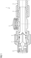
- Figure 1 shows an embodiment of the tire connection valve device 1 according to the invention, which comprises a base body 2.
- a drain valve 3 is arranged on the base body 2 as a push button.
- the base body 2 also has a taper 4 at one end, to which a filling hose 5 is connected. Air and/or sealant is fed into the tire via the tire connection valve device 1 via the filling hose 5.
- the other end of the The base body 2 has a thread 6.
- the car valve is connected to the valve device 1 via the thread 6.
- the valve device 1 also has a closing element 7, which only opens the valve device 1 when it is connected to the car valve.
- the closing element 7 has a projection that projects into the area of the thread 6 and which presses and opens the car valve when it is connected to the tire connection valve device 1.
Landscapes
- Engineering & Computer Science (AREA)
- Mechanical Engineering (AREA)
- Check Valves (AREA)
Description
- Die Erfindung betrifft eine Reifenanschlussventileinrichtung als Verbindungselement zwischen einem Füllschlauch eines Pannenhilfesets und einem Reifenventil eines Fahrzeugreifens gemäß dem Patentanspruch 1 sowie ein Pannenhilfeset zum Abdichten und Aufpumpen von Fahrzeugreifen gemäß dem Patentanspruch 9.
- Reifenanschlussventile für Pannenhilfesets sowie Pannenhilfesets mit Reifenanschlussventilen sind im Stand der Technik bekannt und werden üblicherweise eingesetzt, um das Pannenhilfeset über einen Schlauch mit dem Fahrzeugreifen beziehungsweise dem Ventil des Reifens zu verbinden. Ein Pannenhilfeset umfasst üblicherweise einen Kompressor zur Erzeugung von Druckluft, durch die ein Dichtmittel zum Abdichten eines Fahrzeugreifens im Falle einer Panne in den Fahrzeugreifen gepumpt wird und/oder den Fahrzeugreifen nach dem Abdichten mit Luft zu befüllen.
- Die
DE102015220060 offenbart beispielsweise ein Reifenanschlussventil beziehungsweise einen Adapter als Verbindungselement zwischen einem Füllschlauch eines Pannensets und einem Reifenventil eines Reifens, wobei das Reifenanschlussventil durch einen federbelasteten Ventilkörper selbstschließend ausgebildet ist und der Ventilkörper durch das Aufbringen des Reifenanschlussventils auf das Reifenventil geöffnet wird, wobei das Reifenanschlussventil eine Einrichtung zur lösbaren Verbindung mit dem Reifenventil aufweist. - Die
JP2007182036A - Die
US5070917A beschreibt eine kompakte Vorrichtung zum abgedichteten Speichern und anschließenden Abgeben einer vorgegebenen Lademenge einer Reifendichtflüssigkeit in das Innere eines Reifens umfassend ein hohles Flüssigkeitsspeicher- und -übertragungselement mit einem Einlassanschluss und einem Auslassanschluss, in dem die Dichtflüssigkeit angeordnet ist. - Ferner offenbart die
WO2015145443A1 eine Vorrichtung zum Aufblasen und Abdichten eines aufblasbaren Objekts, die einen luftdichten Schlauch, mindestens einen hermetischen Verbinder, der reversibel mit einem oder beiden Enden des luftdichten Schlauchs verbunden ist, und eine Druckquelle umfasst, die entweder mit einem Ende, dem zweiten Ende oder dem mindestens einen hermetischen Verbinder verbunden ist. - Die
DE102015220060A1 offenbart ein Reifenanschlussventil als Verbindungselement zwischen einem Füllschlauch eines Pannensets und einem Reifenventil eines Reifens, wobei das Reifenanschlussventil durch einen federbelasteten Ventilkörper selbstschließend ausgebildet ist und der Ventilkörper durch das Aufbringen des Reifenanschlussventils auf das Reifenventil geöffnet wird und eine in seinem inneren und für Luft und/oder Dichtmittel vorgesehenen Durchtrittsquerschnitt angeordnete Ringdichtung enthält, die a) in Strömungsrichtung ausgangsseitig eine Dichtfläche zur stirnseitigen Abdichtung des eingeschraubten Reifenventils aufweist, b) auf ihrem Außenumfang und in Strömungsrichtung eingangsseitig Dichtflächen aufweist zur Abdichtung der Rändelmutter gegenüber dem Endstück des Füllschlauches, und c) auf ihrem Innenumfang und in Strömungsrichtung eingangsseitig Dicht- und Anlageflächen zur Anlage des federbelasten Ventilkörpers aufweist. - Die
JP2008002513A - Ferner beschreibt die
EP2186628A1 einen Ventiladapter für ein Abdicht-/Aufpumpgerät, der Luft aus einem Reifen ablassen kann, ohne das im Gerät verbleibende Abdichtmittel freizugeben. - Derzeitige Entwicklungen von Pannenhilfesets führen zu immer kleineren Bauteilen, weshalb funktionelle Elemente, wie beispielsweise ein Ablassventil, am Pannenhilfeset anders als üblich angeordnet werden müssen, damit die Funktionsfähigkeit des Pannenhilfesets für den Verbraucher weiterhin gegeben ist. Problematisch ist, dass diese Bauteile formstabil und kostengünstig herstellbar sein müssen, um den heutigen Anforderungen nachzukommen. Eine entsprechende Problematik gilt für Reifenanschlussventile.
- Hier setzt die vorliegende Erfindung an. Es ist die Aufgabe der Erfindung eine verbesserte Reifenanschlussventileinrichtung bereitzustellen, die einerseits kostengünstig und einfach herstellbar ist und andererseits den Luftdruck regulieren kann. Ferner ist es die Aufgabe der Erfindung ein verbessertes Pannenhilfeset bereitzustellen, welches einerseits kostengünstig herstellbar ist und andererseits eine einfache Möglichkeit der Luftregulierung im Fahrzeugreifen bietet.
- Gelöst wird die Aufgabe durch eine Reifenanschlussventileinrichtung mit den Merkmalen des Patentanspruchs 1. Ferner wird die Aufgabe durch ein Pannenhilfeset mit den Merkmalen des Patentanspruchs 10 gelöst.
- Die Aufgabe wird durch eine Reifenanschlussventileinrichtung als Verbindungselement zwischen einem Füllschlauch eines Pannenhilfesets und einem Reifenventil eines Fahrzeugreifens gelöst, wobei die Reifenanschlussventileinrichtung einen Grundkörper mit einer Einlassöffnung und einer Auslassöffnung aufweist, wobei eine Öffnung zumindest ein Gewinde umfasst, über das die Reifenanschlussventileinrichtung mit dem Reifenventil verbindbar ist, und die Reifenanschlussventileinrichtung ein Ablassventil zur Regulierung der Luft aufweist, wobei das Gewinde Kunststoff umfasst.
- Vorteilhafterweise ist die erfindungsgemäße Reifenanschlussventileinrichtung mit einem Gewinde umfassend Kunststoff formstabil und sowohl einfach als auch kostengünstig herstellbar. Durch die erfindungsgemäße Reifenanschlussventileinrichtung kann die Luftführung im Kompressor erhalten bleiben. Außerdem kann das Gehäuse des Kompressors komprimiert werden, da das Ablassventil in der Reifenanschlussventileinrichtung integriert ist.
- Im Sinne der Erfindung umfasst das Gewinde Kunststoff. Dazu ist der Abschnitt, der das Gewinde aufweist, zumindest teilweise aus Kunststoff. Ein wesentlicher Vorteil von Kunststoff ist die einfache Handhabung im Herstellungsprozess, da die Abschnitte oder Bauteile des Grundkörpers in einem Verfahrensschritt hergestellt werden können. Bevorzugt werden die Abschnitte oder der gesamte Grundkörper im Spritzgussverfahren hergestellt. Andere Verfahren sind ebenfalls denkbar.
- Der Grundkörper ist im Sinne der Erfindung so ausgebildet, dass durch diesen Luft und/oder Dichtmittel strömen kann. Dazu weist dieser mindestens zwei Öffnungen auf, wobei die Luft und/oder das Dichtmittel in die erste Öffnung einströmen und aus der zweiten Öffnung herausströmen kann. Denkbar ist, dass der Grundkörper eine zylindrische Form aufweist.
- In einer bevorzugten Ausführungsform der Erfindung umfasst das Gewinde ein Polyamid, besonders bevorzugt ein Polyamid mit Glasfaserverstärkung. Der Einsatz von Polyamiden ist vorteilhaft, da Polyamide wegen ihrer hervorragenden Festigkeit und Zähigkeit besonders geeignet sind. Bevorzugt weist zumindest der Abschnitt des Gewindes eine Härte nach Shore (A/D) von mindestens D84 auf und/oder eine Zug-Biegemodul im Bereich von 500 bis 16000 MPa, insbesondere nach ISO 527.Ein weiterer Vorteil ist die Wärmeformbeständigkeit B von mindestens 160°C nach ISO 75 HDT/B. Vorteilhafterweise eignen sich Polyamide mit solchen Eigenschaften besonders gut, da diese somit länger haltbar sind und deutlich einfacher produziert werden können. Hinzufügend reduzieren sich die Herstellungskosten. Besonders bevorzugt ist das Polyamid ein Polyamid 66 und/oder ein Polyamid 6, auch PA 66 beziehungsweise PA 6. PA 66 und/oder PA 6 sind vorteilhafterweise besonders formstabil.
- In einer weiteren erfindungsgemäßen Ausführungsform der Erfindung weist die Reifenanschlussventileinrichtung zumindest ein Schließelement auf, welches im Gehäuse angeordnet ist. Das Schließelement ist so ausgebildet, dass es öffnet, wenn das Autoventil mit der Reifenanschlussventileinrichtung verbunden ist. Besonders bevorzugt öffnet sich das Schließelement druckabhängig, nämlich wenn das Fahrzeugreifenventil gegen das Schließelement drückt. Vorteilhafterweise ist die Reifenanschlussventileinrichtung geschlossen, wenn diese nicht mit einem Fahrzeugreifenventil verbunden ist, sodass kein Medium austreten kann. Erst nach Anschluss an das Fahrzeugreifenventil öffnet sich dieses, sodass der Benutzer eine solche Reifenanschlussventileinrichtung sicher einsetzen kann.
- Besonders bevorzugt ist das Gewinde und das Schließelement in den Grundkörper integriert. Vorteilhaft ist sowohl der Grundkörper, das Gewinde und das Schließelement als ein Bauteil ausgebildet, sodass die Herstellung eines solchen Bauteils deutlich einfacher und kostengünstiger ist.
- In einer weiteren bevorzugten Ausführungsform ist die Reifenanschlussventileinrichtung über das Gewinde formschlüssig mit dem Reifenventil verbindbar, sodass Luft und/oder Dichtmittel in den Fahrzeugreifen und/oder Luft über das Ablassventil aus dem Fahrzeugreifen strömbar ist. Vorteilhafterweise ist das Gewinde so ausgebildet, dass es mit dem Reifenventil so verbindbar ist, dass der Reifen im Falle einer Panne mit Luft und/oder Dichtmittel befüllbar ist. Der Luftdruck kann über das Ablassventil zusätzlich reguliert werden.
- Weiter bevorzugt ist das Ablassventil im Wesentlichen mittig in Längserstreckung der Ventileinrichtung angeordnet. Vorteilhafterweise ist das Ablassventil mittig angeordnet, damit die Ventileinrichtung auf der einen Seite mit dem Füllschlauch und auf der anderen Seite über das Gewinde mit dem Reifenventil verbindbar ist. Besonders bevorzugt ist das Ablassventil am Grundkörper angeordnet.
- Ferner bevorzugt ist die Reifenanschlussventileinrichtung, insbesondere der Grundkörper, als ein Bauteil ausgebildet. Besonders bevorzugt umfasst dieser Kunststoff oder besteht aus Kunststoff. Ganz besonders bevorzugt ist der Kunststoff aus einem Polyamid, beispielsweise Polyamid 66 und/oder Polyamid 6. Vorteilhafterweise kann der Grundkörper umfassend das Gewinde in einem Verfahrensschritt hergestellt werden. Ein Grundkörper aus Kunststoff, insbesondere Polyamid, ist besonders formstabil.
- In einer weiteren bevorzugten Ausführungsform der Erfindung ist das Ablassventil als ein Druckschalter ausgebildet, durch den Luft aus dem Fahrzeugreifen beförderbar ist, sobald der Druckschalter betätigt wird. Der Druckschalter kann beispielsweise aus Kunststoff bestehen. Vorteilhafterweise ist der Druckschalter einteilig ausgebildet. Denkbar ist allerdings auch, dass dieser mehrteilig ausgebildet ist.
- Weiterhin bevorzugt ist das Ablassventil eine Öffnung, die ein abschraubbares Verschließelement aufweist. Das Verschließelement könnte beispielsweise Kunststoff, insbesondere Polyamid, Polyamid 66 und/oder Polyamid 6, umfassen. Vorteilhafterweise kann ein solches Verschließelement das Ablassventil wieder dann verschließen, wenn der gewünschte Luftdruck im Reifen erreicht ist. Außerdem ist es möglich, dass der Benutzer die Luftzufuhr insgesamt regulieren kann.
- In einer weiteren bevorzugten Ausführungsform der Erfindung weist der Grundkörper ein Anschlusselement auf, durch das dieser mit einem Füllschlauch oder mit einer Dichtmittelflasche verbindbar ist. Das Anschlusselement kann beispielsweise verjüngt sein, damit der Füllschlauch auf den Anschluss gesteckt werden kann.
- Weiterhin wird die Aufgabe der Erfindung durch ein Pannenhilfeset zum Abdichten und Aufpumpen von Fahrzeugreifen gelöst, umfassend einen Kompressor mit einem Elektromotor zur Erzeugung des Abdicht- und/oder Pumpdrucks, einen Anschluss für einen Behälter mit Dichtmittel sowie einen Füllschlauch, durch welchen Luft und/oder Dichtmittel über den Kompressor strömbar ist, dadurch gekennzeichnet, dass das Pannenhilfeset eine beschriebene Reifenanschlussventileinrichtung umfasst.
- Vorteilhafterweise ist der Einsatz eines solchen erfindungsgemäßen Pannenhilfesets für den Benutzer einfach und sicher zu bedienen, da dieses ein Ablassventil an der Reifenanschlussventileinrichtung aufweist. Das Pannenhilfeset mit einem solchen Reifenanschlussventileinrichtung, wobei dieses zumindest ein Gewinde umfassend Kunststoff, aufweist, ist deutlich einfacher herzustellen und zeigt verbesserte Stabilitäten hinsichtlich der Verwendungsdauer.
- Weitere Vorteile und Merkmale der erfindungsgemäßen Reifenanschlussventileinrichtung und des Pannenhilfesets ergeben sich nebst der Beschreibung zusätzlich aus den Unteransprüchen, die sich auf vorteilhafte Ausgestaltungen der vorliegenden Erfindung beziehen und als solche nicht einschränkend zu verstehen sind. Von der Erfindung mit umfasst sind auch Kombinationen der Merkmale verschiedener Unteransprüche, auch wenn sich die Unteransprüche nicht aufeinander beziehen oder wenn diese verschiedenen Anspruchskategorien zugehören. Ferner sind auch Kombinationen von bevorzugten und besonders bevorzugten Ausführungsformen untereinander miteinander kombinierbar. Dies gilt auch für die einzelnen Merkmale des nachfolgenden diskutierten Ausführungsbeispiels, soweit diese nicht für den Fachmann als zwingend zueinander gehörig erkennbar sind.
- Weitere Einzelheiten und Vorteile der vorliegenden Erfindung ergeben sich aus der nachfolgenden Beschreibung des Ausführungsführungsbeispiels in Verbindung mit der Zeichnung. In dieser zeigt
- Figur 1
- eine Ausführungsform der erfindungsgemäßen Reifenanschlussventileinrichtung.
-
Figur 1 zeigt eine Ausführungsform der erfindungsgemäßen Reifenanschlussventileinrichtung 1, welche einen Grundkörper 2 umfasst. Am Grundkörper 2 ist ein Ablassventil 3 als Druckknopf angeordnet. Ferner weist der Grundkörper 2 an einem Ende eine Verjüngung 4 auf, an der ein Füllschlauch 5 angeschlossen ist. Über den Füllschlauch 5 wird Luft und/oder Dichtmittel über die Reifenanschlussventileinrichtung 1 in den Reifen gefördert. Das andere Ende des Grundkörpers 2 weist ein Gewinde 6 auf. Über das Gewinde 6 wird das Autoventil mit der Ventileinrichtung 1 verbunden. Ferner weist die Ventileinrichtung 1 ein Schließelement 7 auf, welches die Ventileinrichtung 1 erst öffnet, wenn diese mit dem Autoventil verbunden wird. Dazu weist das Schließelement 7 einen Vorsprung auf, der in den Bereich des Gewindes 6 hineinragt und welches das Autoventil drückt und öffnet, wenn dieses mit der Reifenanschlussventileinrichtung 1 verbunden wird. -
- 1
- Reifenanschlussventileinrichtung
- 2
- Grundkörper
- 3
- Ablassventil
- 4
- Verjüngung
- 5
- Füllschlauch
- 6
- Gewinde
- 7
- Schließelement
Claims (9)
- Reifenanschlussventileinrichtung (1) als Verbindungselement zwischen einem Füllschlauch eines Pannenhilfesets und einem Reifenventil eines Fahrzeugreifens, wobei die Reifenanschlussventileinrichtung (1) einen Grundkörper (2) mit einer Einlassöffnung und einer Auslassöffnung aufweist, wobei eine Öffnung zumindest ein Gewinde (6) umfasst, über das die Reifenanschlussventileinrichtung (1) mit dem Reifenventil verbindbar ist, und die Reifenanschlussventileinrichtung (1) ein Ablassventil (3) zur Regulierung der Luft aufweist, wobei die Reifenanschlussventileinrichtung (1) zumindest ein Schließelement (7) aufweist, welches im Gehäuse angeordnet ist, wobei die Reifenanschlussventileinrichtung (1) erst öffnet, wenn diese mit einem Autoventil verbunden wird,dadurch gekennzeichnet, dass der Grundkörper (2), das Gewinde (6) und das Schließelement (7) als ein Bauteil ausgebildet ist, wobeidas Gewinde (6) Kunststoff umfasst.
- Reifenanschlussventileinrichtung (1) nach Anspruch 1, dadurch gekennzeichnet, dass das Gewinde (6) ein Polyamid, bevorzugt ein Polyamid mit Glasfaserverstärkung umfasst, wobei das Polyamid ganz bevorzugt ein Polyamid 66 und/oder Polyamid 6 umfasst.
- Reifenanschlussventileinrichtung (1) nach Anspruch 1 oder 2, dadurch gekennzeichnet, dass die Reifenanschlussventileinrichtung (1) über das Gewinde (6) formschlüssig mit dem Reifenventil verbindbar ist, sodass Luft und/oder Dichtmittel in den Fahrzeugreifen und/oder Luft über das Ablassventil (3) aus dem Fahrzeugreifen strömbar ist.
- Reifenanschlussventileinrichtung (1) nach einem der vorherigen Ansprüche, dadurch gekennzeichnet, dass das Ablassventil (3) im Wesentlichen mittig in Längserstreckung der Reifenanschlussventileinrichtung (1), insbesondere am Grundkörper (2), angeordnet ist.
- Reifenanschlussventileinrichtung (1) nach einem der vorherigen Ansprüche, dadurch gekennzeichnet, dass die Reifenanschlussventileinrichtung (1), insbesondere der Grundkörper (2), als ein Bauteil ausgebildet ist und bevorzugt Kunststoff umfasst oder aus Kunststoff besteht, besonders bevorzugt aus Polyamid 66 und/oder Polyamid 6.
- Reifenanschlussventileinrichtung (1) nach einem der vorherigen Ansprüche, dadurch gekennzeichnet, dass das Ablassventil (3) als ein Druckschalter ausgebildet ist, durch den Luft aus dem Fahrzeugreifen beförderbar ist, sobald der Druckschalter betätigt wird.
- Reifenanschlussventileinrichtung (1) nach einem der vorherigen Ansprüche, dadurch gekennzeichnet, dass das Ablassventil (3) eine Öffnung ist, die ein abschraubbares Verschließelement aufweist.
- Reifenanschlussventileinrichtung (1) nach einem der vorherigen Ansprüche, dadurch gekennzeichnet, dass der Grundkörper (2) ein Anschlusselement aufweist, durch das dieser mit einem Schlauch (5) oder mit einer Dichtmittelflasche verbindbar ist.
- Pannenhilfeset zum Abdichten und Aufpumpen von Fahrzeugreifen, umfassend einen Kompressor mit einem Elektromotor zur Erzeugung des Abdicht- und/oder Pumpdrucks, einen Anschluss für einen Behälter mit Dichtmittel sowie einen Füllschlauch, durch welchen Luft und/oder Dichtmittel über den Kompressor strömbar ist, dadurch gekennzeichnet, dass das Pannenhilfeset eine Reifenanschlussventileinrichtung (1) nach einem der vorherigen Ansprüche umfasst.
Applications Claiming Priority (1)
| Application Number | Priority Date | Filing Date | Title |
|---|---|---|---|
| DE102021211788.0A DE102021211788A1 (de) | 2021-10-19 | 2021-10-19 | Reifenanschlussventileinrichtung zum Verbinden eines Pannenhilfesets mit einem Reifenventil und Pannenhilfeset mit einer solchen |
Publications (2)
| Publication Number | Publication Date |
|---|---|
| EP4169745A1 EP4169745A1 (de) | 2023-04-26 |
| EP4169745B1 true EP4169745B1 (de) | 2025-01-15 |
Family
ID=83689635
Family Applications (1)
| Application Number | Title | Priority Date | Filing Date |
|---|---|---|---|
| EP22200540.7A Active EP4169745B1 (de) | 2021-10-19 | 2022-10-10 | Reifenanschlussventileinrichtung zum verbinden eines pannenhilfesets mit einem reifenventil und pannenhilfeset mit einer solchen reifenanschlussventileinrichtung |
Country Status (3)
| Country | Link |
|---|---|
| EP (1) | EP4169745B1 (de) |
| DE (1) | DE102021211788A1 (de) |
| PL (1) | PL4169745T3 (de) |
Family Cites Families (6)
| Publication number | Priority date | Publication date | Assignee | Title |
|---|---|---|---|---|
| US5070917A (en) * | 1989-06-14 | 1991-12-10 | Ferris James E | Pressurized fluid-drivable device for injecting a treatment liquid stored therein into a tire or other enclosed space |
| JP2007182036A (ja) * | 2006-01-10 | 2007-07-19 | Bridgestone Corp | コネクタ、及び、コネクタセット |
| JP5021242B2 (ja) * | 2006-06-20 | 2012-09-05 | 株式会社ブリヂストン | シーリングポンプアップ装置 |
| JP4927657B2 (ja) * | 2007-07-27 | 2012-05-09 | 株式会社ブリヂストン | バルブアダプタ、及びこれを備えたシーリング・ポンプアップ装置 |
| BR112016022198A2 (pt) * | 2014-03-28 | 2017-08-15 | Franklin Aharon Amitai | Dispositivo para inflar e vedar um objeto inflável, método de inflação e vedação de objetos infláveis, dispositivo para inflar e vedar um pneu pneumático, método de inflação e vedação de um pneu pneumático, dispositivo infalível para inflação e vedação de um pneu pneumático, dispositivo de liberação de agente selante a um pneu pneumático, e, método para injeção de selante aos pneus pneumáticos tendo algum grau de pressão presente nos ditos pneus |
| DE102015220060A1 (de) | 2015-10-15 | 2017-04-20 | Continental Reifen Deutschland Gmbh | Reifenanschlussventil |
-
2021
- 2021-10-19 DE DE102021211788.0A patent/DE102021211788A1/de active Pending
-
2022
- 2022-10-10 EP EP22200540.7A patent/EP4169745B1/de active Active
- 2022-10-10 PL PL22200540.7T patent/PL4169745T3/pl unknown
Also Published As
| Publication number | Publication date |
|---|---|
| DE102021211788A1 (de) | 2023-04-20 |
| PL4169745T3 (pl) | 2025-06-09 |
| EP4169745A1 (de) | 2023-04-26 |
Similar Documents
| Publication | Publication Date | Title |
|---|---|---|
| EP1121324B2 (de) | Abdichtvorrichtung | |
| EP2338671B1 (de) | Vorrichtung zum Einbringen von Luft und/oder Abdichtmittel in einen Reifen | |
| DE69621424T2 (de) | Ventilverbindung | |
| EP1299227B1 (de) | Abdichtvorrichtung | |
| EP2807018B1 (de) | Rückflusssicherung | |
| WO2009065653A1 (de) | Vorrichtung mit einer schaltmarkierung zum abdichten und aufpumpen aufblasbarer gegenstände | |
| DE102007053241A1 (de) | Vorrichtung mit einer Ventileinheit zum Abdichten und Aufpumpen aufblasbarer Gegenstände | |
| EP2276624B1 (de) | Pannenhilfesystem | |
| EP0908651A3 (de) | Rückschlagventileinrichtung | |
| EP4169745B1 (de) | Reifenanschlussventileinrichtung zum verbinden eines pannenhilfesets mit einem reifenventil und pannenhilfeset mit einer solchen reifenanschlussventileinrichtung | |
| WO2006133961A2 (de) | Einrichtung zum zuführen von dichtungsflüssigkeit in einen luftreifen | |
| DE102015220060A1 (de) | Reifenanschlussventil | |
| EP3976361B1 (de) | Verteilervorrichtung zum einbringen von druckluft und/oder dichtmittel in einen fahrzeugluftreifen sowie verwendung einer abdeckeinheit der verteilervorrichtung und ein verfahren zum einbringen von druckluft und/oder dichtmittel in einen fahrzeugluftreifen | |
| EP4169746B1 (de) | Vorrichtung zur regulierung der druckluft in einem fahrzeugreifen, pannenhilfeset umfassend eine solche vorrichtung und verfahren zur regulierung der druckluft in einem fahrzeugreifen mit einer solchen vorrichtung | |
| EP2212101B1 (de) | Vorrichtung mit einer steckverbindung zum abdichten und aufpumpen aufblasbarer gegenstände | |
| EP3068616B1 (de) | Vorrichtung zum abdichten und aufpumpen aufblasbarer gegenstände | |
| EP4173809B1 (de) | Pannenhilfeset umfassend eine messeinrichtung mit druckablasseinrichtung und verfahren zur regulierung der druckluft in einem fahrzeugreifen mit einem pannenhilfeset | |
| DE202004009114U1 (de) | Reifenabdichteinheit | |
| DE9210467U1 (de) | Reifenfüllgerät | |
| DE102021205682A1 (de) | Dichtmittelvorrichtung zum Abdichten eines Fahrzeugreifens, Pannenhilfeset mit einer solchen Dichtmittelvorrichtung sowie ein Verfahren zur Herstellung einer solchen Dichtmittelvorrichtung | |
| DE19804654A1 (de) | Vorrichtung zum Prüfen des Luftdrucks eines Reifens und gegebenenfalls zum Füllen des Reifens | |
| WO2015070999A1 (de) | Vorrichtung zum abdichten und aufpumpen aufblasbarer gegenstände mit lageventil | |
| DE202020105286U1 (de) | Rückschlagverbinder zum Verbinden mit dem Luftventil eines Reifens und dem Schlauchverbinder eines Luftkompressors | |
| EP3054157A1 (de) | Pumpenkopf zur verbindung einer luftpumpe mit einem ventil eines schlauchlosen fahrradreifens sowie eine pumpe mit einem derartigen pumpenkopf | |
| DE202005008647U1 (de) | Druckmessgerät |
Legal Events
| Date | Code | Title | Description |
|---|---|---|---|
| PUAI | Public reference made under article 153(3) epc to a published international application that has entered the european phase |
Free format text: ORIGINAL CODE: 0009012 |
|
| STAA | Information on the status of an ep patent application or granted ep patent |
Free format text: STATUS: THE APPLICATION HAS BEEN PUBLISHED |
|
| AK | Designated contracting states |
Kind code of ref document: A1 Designated state(s): AL AT BE BG CH CY CZ DE DK EE ES FI FR GB GR HR HU IE IS IT LI LT LU LV MC ME MK MT NL NO PL PT RO RS SE SI SK SM TR |
|
| STAA | Information on the status of an ep patent application or granted ep patent |
Free format text: STATUS: REQUEST FOR EXAMINATION WAS MADE |
|
| 17P | Request for examination filed |
Effective date: 20231026 |
|
| RBV | Designated contracting states (corrected) |
Designated state(s): AL AT BE BG CH CY CZ DE DK EE ES FI FR GB GR HR HU IE IS IT LI LT LU LV MC ME MK MT NL NO PL PT RO RS SE SI SK SM TR |
|
| STAA | Information on the status of an ep patent application or granted ep patent |
Free format text: STATUS: EXAMINATION IS IN PROGRESS |
|
| 17Q | First examination report despatched |
Effective date: 20240130 |
|
| RAP3 | Party data changed (applicant data changed or rights of an application transferred) |
Owner name: CONTINENTAL REIFEN DEUTSCHLAND GMBH |
|
| GRAP | Despatch of communication of intention to grant a patent |
Free format text: ORIGINAL CODE: EPIDOSNIGR1 |
|
| STAA | Information on the status of an ep patent application or granted ep patent |
Free format text: STATUS: GRANT OF PATENT IS INTENDED |
|
| INTG | Intention to grant announced |
Effective date: 20240912 |
|
| GRAS | Grant fee paid |
Free format text: ORIGINAL CODE: EPIDOSNIGR3 |
|
| GRAA | (expected) grant |
Free format text: ORIGINAL CODE: 0009210 |
|
| STAA | Information on the status of an ep patent application or granted ep patent |
Free format text: STATUS: THE PATENT HAS BEEN GRANTED |
|
| P01 | Opt-out of the competence of the unified patent court (upc) registered |
Free format text: CASE NUMBER: APP_62760/2024 Effective date: 20241126 |
|
| AK | Designated contracting states |
Kind code of ref document: B1 Designated state(s): AL AT BE BG CH CY CZ DE DK EE ES FI FR GB GR HR HU IE IS IT LI LT LU LV MC ME MK MT NL NO PL PT RO RS SE SI SK SM TR |
|
| REG | Reference to a national code |
Ref country code: CH Ref legal event code: EP Ref country code: GB Ref legal event code: FG4D Free format text: NOT ENGLISH |
|
| REG | Reference to a national code |
Ref country code: DE Ref legal event code: R096 Ref document number: 502022002627 Country of ref document: DE |
|
| REG | Reference to a national code |
Ref country code: IE Ref legal event code: FG4D Free format text: LANGUAGE OF EP DOCUMENT: GERMAN |
|
| REG | Reference to a national code |
Ref country code: NL Ref legal event code: MP Effective date: 20250115 |
|
| PG25 | Lapsed in a contracting state [announced via postgrant information from national office to epo] |
Ref country code: NL Free format text: LAPSE BECAUSE OF FAILURE TO SUBMIT A TRANSLATION OF THE DESCRIPTION OR TO PAY THE FEE WITHIN THE PRESCRIBED TIME-LIMIT Effective date: 20250115 |
|
| PG25 | Lapsed in a contracting state [announced via postgrant information from national office to epo] |
Ref country code: RS Free format text: LAPSE BECAUSE OF FAILURE TO SUBMIT A TRANSLATION OF THE DESCRIPTION OR TO PAY THE FEE WITHIN THE PRESCRIBED TIME-LIMIT Effective date: 20250415 |
|
| PG25 | Lapsed in a contracting state [announced via postgrant information from national office to epo] |
Ref country code: FI Free format text: LAPSE BECAUSE OF FAILURE TO SUBMIT A TRANSLATION OF THE DESCRIPTION OR TO PAY THE FEE WITHIN THE PRESCRIBED TIME-LIMIT Effective date: 20250115 |
|
| PG25 | Lapsed in a contracting state [announced via postgrant information from national office to epo] |
Ref country code: ES Free format text: LAPSE BECAUSE OF FAILURE TO SUBMIT A TRANSLATION OF THE DESCRIPTION OR TO PAY THE FEE WITHIN THE PRESCRIBED TIME-LIMIT Effective date: 20250115 |
|
| REG | Reference to a national code |
Ref country code: LT Ref legal event code: MG9D |
|
| PG25 | Lapsed in a contracting state [announced via postgrant information from national office to epo] |
Ref country code: IS Free format text: LAPSE BECAUSE OF FAILURE TO SUBMIT A TRANSLATION OF THE DESCRIPTION OR TO PAY THE FEE WITHIN THE PRESCRIBED TIME-LIMIT Effective date: 20250515 Ref country code: NO Free format text: LAPSE BECAUSE OF FAILURE TO SUBMIT A TRANSLATION OF THE DESCRIPTION OR TO PAY THE FEE WITHIN THE PRESCRIBED TIME-LIMIT Effective date: 20250415 |
|
| PG25 | Lapsed in a contracting state [announced via postgrant information from national office to epo] |
Ref country code: HR Free format text: LAPSE BECAUSE OF FAILURE TO SUBMIT A TRANSLATION OF THE DESCRIPTION OR TO PAY THE FEE WITHIN THE PRESCRIBED TIME-LIMIT Effective date: 20250115 |
|
| PG25 | Lapsed in a contracting state [announced via postgrant information from national office to epo] |
Ref country code: LV Free format text: LAPSE BECAUSE OF FAILURE TO SUBMIT A TRANSLATION OF THE DESCRIPTION OR TO PAY THE FEE WITHIN THE PRESCRIBED TIME-LIMIT Effective date: 20250115 Ref country code: PT Free format text: LAPSE BECAUSE OF FAILURE TO SUBMIT A TRANSLATION OF THE DESCRIPTION OR TO PAY THE FEE WITHIN THE PRESCRIBED TIME-LIMIT Effective date: 20250515 |
|
| PG25 | Lapsed in a contracting state [announced via postgrant information from national office to epo] |
Ref country code: BG Free format text: LAPSE BECAUSE OF FAILURE TO SUBMIT A TRANSLATION OF THE DESCRIPTION OR TO PAY THE FEE WITHIN THE PRESCRIBED TIME-LIMIT Effective date: 20250115 Ref country code: GR Free format text: LAPSE BECAUSE OF FAILURE TO SUBMIT A TRANSLATION OF THE DESCRIPTION OR TO PAY THE FEE WITHIN THE PRESCRIBED TIME-LIMIT Effective date: 20250416 |
|
| PG25 | Lapsed in a contracting state [announced via postgrant information from national office to epo] |
Ref country code: SE Free format text: LAPSE BECAUSE OF FAILURE TO SUBMIT A TRANSLATION OF THE DESCRIPTION OR TO PAY THE FEE WITHIN THE PRESCRIBED TIME-LIMIT Effective date: 20250115 |
|
| PG25 | Lapsed in a contracting state [announced via postgrant information from national office to epo] |
Ref country code: SM Free format text: LAPSE BECAUSE OF FAILURE TO SUBMIT A TRANSLATION OF THE DESCRIPTION OR TO PAY THE FEE WITHIN THE PRESCRIBED TIME-LIMIT Effective date: 20250115 |
|
| PG25 | Lapsed in a contracting state [announced via postgrant information from national office to epo] |
Ref country code: DK Free format text: LAPSE BECAUSE OF FAILURE TO SUBMIT A TRANSLATION OF THE DESCRIPTION OR TO PAY THE FEE WITHIN THE PRESCRIBED TIME-LIMIT Effective date: 20250115 |
|
| PG25 | Lapsed in a contracting state [announced via postgrant information from national office to epo] |
Ref country code: IT Free format text: LAPSE BECAUSE OF FAILURE TO SUBMIT A TRANSLATION OF THE DESCRIPTION OR TO PAY THE FEE WITHIN THE PRESCRIBED TIME-LIMIT Effective date: 20250115 |
|
| REG | Reference to a national code |
Ref country code: DE Ref legal event code: R097 Ref document number: 502022002627 Country of ref document: DE |
|
| PG25 | Lapsed in a contracting state [announced via postgrant information from national office to epo] |
Ref country code: CZ Free format text: LAPSE BECAUSE OF FAILURE TO SUBMIT A TRANSLATION OF THE DESCRIPTION OR TO PAY THE FEE WITHIN THE PRESCRIBED TIME-LIMIT Effective date: 20250115 Ref country code: EE Free format text: LAPSE BECAUSE OF FAILURE TO SUBMIT A TRANSLATION OF THE DESCRIPTION OR TO PAY THE FEE WITHIN THE PRESCRIBED TIME-LIMIT Effective date: 20250115 |
|
| PG25 | Lapsed in a contracting state [announced via postgrant information from national office to epo] |
Ref country code: RO Free format text: LAPSE BECAUSE OF FAILURE TO SUBMIT A TRANSLATION OF THE DESCRIPTION OR TO PAY THE FEE WITHIN THE PRESCRIBED TIME-LIMIT Effective date: 20250115 |
|
| PG25 | Lapsed in a contracting state [announced via postgrant information from national office to epo] |
Ref country code: SK Free format text: LAPSE BECAUSE OF FAILURE TO SUBMIT A TRANSLATION OF THE DESCRIPTION OR TO PAY THE FEE WITHIN THE PRESCRIBED TIME-LIMIT Effective date: 20250115 |
|
| PLBE | No opposition filed within time limit |
Free format text: ORIGINAL CODE: 0009261 |
|
| STAA | Information on the status of an ep patent application or granted ep patent |
Free format text: STATUS: NO OPPOSITION FILED WITHIN TIME LIMIT |
|
| 26N | No opposition filed |
Effective date: 20251016 |
|
| PGFP | Annual fee paid to national office [announced via postgrant information from national office to epo] |
Ref country code: DE Payment date: 20251031 Year of fee payment: 4 |
|
| PGFP | Annual fee paid to national office [announced via postgrant information from national office to epo] |
Ref country code: AT Payment date: 20260113 Year of fee payment: 4 |
|
| PGFP | Annual fee paid to national office [announced via postgrant information from national office to epo] |
Ref country code: PL Payment date: 20251006 Year of fee payment: 4 |