EP4169750B1 - Système de suspension de véhicule avec un assemblage de solénoïde connecté à la tige de piston de l'amortisseur - Google Patents
Système de suspension de véhicule avec un assemblage de solénoïde connecté à la tige de piston de l'amortisseur Download PDFInfo
- Publication number
- EP4169750B1 EP4169750B1 EP22197749.9A EP22197749A EP4169750B1 EP 4169750 B1 EP4169750 B1 EP 4169750B1 EP 22197749 A EP22197749 A EP 22197749A EP 4169750 B1 EP4169750 B1 EP 4169750B1
- Authority
- EP
- European Patent Office
- Prior art keywords
- suspension system
- core
- set forth
- induction plate
- aperture
- Prior art date
- Legal status (The legal status is an assumption and is not a legal conclusion. Google has not performed a legal analysis and makes no representation as to the accuracy of the status listed.)
- Active
Links
Images


Classifications
-
- B—PERFORMING OPERATIONS; TRANSPORTING
- B60—VEHICLES IN GENERAL
- B60G—VEHICLE SUSPENSION ARRANGEMENTS
- B60G17/00—Resilient suspensions having means for adjusting the spring or vibration-damper characteristics, for regulating the distance between a supporting surface and a sprung part of vehicle or for locking suspension during use to meet varying vehicular or surface conditions, e.g. due to speed or load
- B60G17/06—Characteristics of dampers, e.g. mechanical dampers
- B60G17/08—Characteristics of fluid dampers
-
- B—PERFORMING OPERATIONS; TRANSPORTING
- B60—VEHICLES IN GENERAL
- B60G—VEHICLE SUSPENSION ARRANGEMENTS
- B60G17/00—Resilient suspensions having means for adjusting the spring or vibration-damper characteristics, for regulating the distance between a supporting surface and a sprung part of vehicle or for locking suspension during use to meet varying vehicular or surface conditions, e.g. due to speed or load
- B60G17/015—Resilient suspensions having means for adjusting the spring or vibration-damper characteristics, for regulating the distance between a supporting surface and a sprung part of vehicle or for locking suspension during use to meet varying vehicular or surface conditions, e.g. due to speed or load the regulating means comprising electric or electronic elements
- B60G17/0152—Resilient suspensions having means for adjusting the spring or vibration-damper characteristics, for regulating the distance between a supporting surface and a sprung part of vehicle or for locking suspension during use to meet varying vehicular or surface conditions, e.g. due to speed or load the regulating means comprising electric or electronic elements characterised by the action on a particular type of suspension unit
- B60G17/0157—Resilient suspensions having means for adjusting the spring or vibration-damper characteristics, for regulating the distance between a supporting surface and a sprung part of vehicle or for locking suspension during use to meet varying vehicular or surface conditions, e.g. due to speed or load the regulating means comprising electric or electronic elements characterised by the action on a particular type of suspension unit non-fluid unit, e.g. electric motor
-
- F—MECHANICAL ENGINEERING; LIGHTING; HEATING; WEAPONS; BLASTING
- F16—ENGINEERING ELEMENTS AND UNITS; GENERAL MEASURES FOR PRODUCING AND MAINTAINING EFFECTIVE FUNCTIONING OF MACHINES OR INSTALLATIONS; THERMAL INSULATION IN GENERAL
- F16F—SPRINGS; SHOCK-ABSORBERS; MEANS FOR DAMPING VIBRATION
- F16F9/00—Springs, vibration-dampers, shock-absorbers, or similarly-constructed movement-dampers using a fluid or the equivalent as damping medium
- F16F9/32—Details
- F16F9/44—Means on or in the damper for manual or non-automatic adjustment; such means combined with temperature correction
- F16F9/46—Means on or in the damper for manual or non-automatic adjustment; such means combined with temperature correction allowing control from a distance, i.e. location of means for control input being remote from site of valves, e.g. on damper external wall
- F16F9/464—Control of valve bias or pre-stress, e.g. electromagnetically
-
- F—MECHANICAL ENGINEERING; LIGHTING; HEATING; WEAPONS; BLASTING
- F16—ENGINEERING ELEMENTS AND UNITS; GENERAL MEASURES FOR PRODUCING AND MAINTAINING EFFECTIVE FUNCTIONING OF MACHINES OR INSTALLATIONS; THERMAL INSULATION IN GENERAL
- F16F—SPRINGS; SHOCK-ABSORBERS; MEANS FOR DAMPING VIBRATION
- F16F9/00—Springs, vibration-dampers, shock-absorbers, or similarly-constructed movement-dampers using a fluid or the equivalent as damping medium
- F16F9/32—Details
- F16F9/44—Means on or in the damper for manual or non-automatic adjustment; such means combined with temperature correction
- F16F9/46—Means on or in the damper for manual or non-automatic adjustment; such means combined with temperature correction allowing control from a distance, i.e. location of means for control input being remote from site of valves, e.g. on damper external wall
- F16F9/466—Throttling control, i.e. regulation of flow passage geometry
- F16F9/469—Valves incorporated in the piston
-
- H—ELECTRICITY
- H01—ELECTRIC ELEMENTS
- H01F—MAGNETS; INDUCTANCES; TRANSFORMERS; SELECTION OF MATERIALS FOR THEIR MAGNETIC PROPERTIES
- H01F7/00—Magnets
- H01F7/06—Electromagnets; Actuators including electromagnets
- H01F7/08—Electromagnets; Actuators including electromagnets with armatures
- H01F7/10—Electromagnets; Actuators including electromagnets with armatures specially adapted for alternating current
- H01F7/11—Electromagnets; Actuators including electromagnets with armatures specially adapted for alternating current reducing or eliminating the effects of eddy currents
-
- B—PERFORMING OPERATIONS; TRANSPORTING
- B60—VEHICLES IN GENERAL
- B60G—VEHICLE SUSPENSION ARRANGEMENTS
- B60G2202/00—Indexing codes relating to the type of spring, damper or actuator
- B60G2202/20—Type of damper
- B60G2202/24—Fluid damper
-
- B—PERFORMING OPERATIONS; TRANSPORTING
- B60—VEHICLES IN GENERAL
- B60G—VEHICLE SUSPENSION ARRANGEMENTS
- B60G2206/00—Indexing codes related to the manufacturing of suspensions: constructional features, the materials used, procedures or tools
- B60G2206/01—Constructional features of suspension elements, e.g. arms, dampers, springs
- B60G2206/40—Constructional features of dampers and/or springs
- B60G2206/41—Dampers
-
- B—PERFORMING OPERATIONS; TRANSPORTING
- B60—VEHICLES IN GENERAL
- B60G—VEHICLE SUSPENSION ARRANGEMENTS
- B60G2500/00—Indexing codes relating to the regulated action or device
- B60G2500/10—Damping action or damper
- B60G2500/102—Damping action or damper stepwise
-
- B—PERFORMING OPERATIONS; TRANSPORTING
- B60—VEHICLES IN GENERAL
- B60G—VEHICLE SUSPENSION ARRANGEMENTS
- B60G2500/00—Indexing codes relating to the regulated action or device
- B60G2500/10—Damping action or damper
- B60G2500/11—Damping valves
-
- B—PERFORMING OPERATIONS; TRANSPORTING
- B60—VEHICLES IN GENERAL
- B60G—VEHICLE SUSPENSION ARRANGEMENTS
- B60G2600/00—Indexing codes relating to particular elements, systems or processes used on suspension systems or suspension control systems
- B60G2600/22—Magnetic elements
- B60G2600/26—Electromagnets; Solenoids
-
- H—ELECTRICITY
- H01—ELECTRIC ELEMENTS
- H01F—MAGNETS; INDUCTANCES; TRANSFORMERS; SELECTION OF MATERIALS FOR THEIR MAGNETIC PROPERTIES
- H01F7/00—Magnets
- H01F7/06—Electromagnets; Actuators including electromagnets
- H01F7/08—Electromagnets; Actuators including electromagnets with armatures
- H01F7/081—Magnetic constructions
-
- H—ELECTRICITY
- H01—ELECTRIC ELEMENTS
- H01F—MAGNETS; INDUCTANCES; TRANSFORMERS; SELECTION OF MATERIALS FOR THEIR MAGNETIC PROPERTIES
- H01F7/00—Magnets
- H01F7/06—Electromagnets; Actuators including electromagnets
- H01F7/08—Electromagnets; Actuators including electromagnets with armatures
- H01F7/16—Rectilinearly-movable armatures
- H01F7/1638—Armatures not entering the winding
Definitions
- the present invention generally relates to a suspension system with a solenoid assembly.
- Vehicles such as automobiles, typically have a suspension system that includes absorber units that are mounted between wheels of the vehicle and a vehicle body or substructure.
- the suspension system is generally configured based on vehicle integration to keep wheels in contact with a driving surface by absorbing energy from forces on the wheels or other portions of the vehicle.
- absorber units As technology continues to evolve, various types of absorber units have been developed.
- One particularly popular type of absorber unit is configured to be operable in one of two different stiffness settings. The two different stiffness settings may also be known as "comfort mode" and "sport mode,” respectfully.
- the absorber unit includes a piston assembly disposed on a center axis.
- the piston assembly includes a piston rod disposed on the center axis and attached to a piston head.
- a regulator is attached to the piston rod and defines a compartment to receive the piston head.
- the regulator has a first aperture and a second aperture.
- a restrictor divides the compartment into a first and second portion.
- An actuator is disposed in the compartment and movable between an opened and a closed position.
- a coil is disposed about a core for generating an electromagnetic field to switch between the operational stiffness settings. When switching between stiffness settings, instability and system behavior deviates from either comfort or sport modes as a result of a magnetic force ripple reacting to a varying input frequency to the coil.
- Document KR20040049230A discloses a piston valve device of damper using magneto-rheological fluid.
- a piston valve apparatus comprises a core having a through hole including the threaded part, a flange, and a fitting sill; a bobbin installed around the core; a solenoid installed in the bobbin to form the magnetic field in applying current; a pole piece fitted from the lower part of the core to the fitting sill to support the lower part of the bobbin and to control damping force by forming the magnetic path flowing the magnetic field from the solenoid; a piston rod combined with the threaded part of the through hole of the core, and composed of a cable passage; a cable electrically connected to the solenoid via the through hole of the core from the cable passage of the piston rod; an upper plate having plural oil pass holes, and keeping the concentricity of the piston rod and the piston valve with fitting to the upper flange of the core; a supporter fitted to the lower part of the core to support the core and the pole piece; an inverse U-shaped flux ring composed of plural oil pass holes, and combined with the upper part of the upper plate to keep the closed loop
- a piston assembly for a damper includes a main piston disposed on a center axis.
- a piston rod is attached to the main piston.
- a regulator extends between the piston rod and the main piston defining a compartment.
- the regulator has at least one first aperture and at least one second aperture.
- a restrictor divides the compartment into a first and second portion.
- An actuator having a core is disposed in the first portion movable between an opened and a closed position.
- the restrictor includes a sleeve disposed in the compartment and attached to the regulator.
- the sleeve defines a hole in fluid communication with the first and second portions and flares outwardly in the first portion toward the regulator to define a slanted edge extending at an oblique angle relative to the center axis to allow the working fluid to flow smoothly thereby limiting noises generated.
- the invention provides for suspension system with a solenoid assembly that improves upon the operational framework and efficiency of suspension systems that offer switchable modes of stiffness by providing an induction plate that reduces or eliminates magnetic force ripple caused by a varying input frequency to a coil.
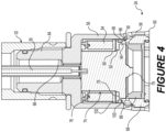
- the solenoid assembly comprises a core including a core head and a core body.
- a spool extends about the core body and defines a space.
- a coil is wrapped around the spool within the space and an induction plate is at least partially located between the spool and the core head.
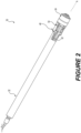
- the suspension system comprises an outer reservoir tube extending along an axis between a first end and a second end and defining a chamber.
- a piston assembly is at least partially located in the chamber.
- the piston assembly includes a piston rod and a piston head.
- a solenoid assembly is connected to the piston rod and includes a body defining a compartment.
- the solenoid assembly comprises a core including a core head and a core body, and located in the compartment.
- a spool extends about the core body and defines a space.
- a coil is wrapped around the spool within the space.
- An induction plate is at least partially located between the spool and the core head.
- An actuator is at least partially located in the compartment adjacent to the core and movable between a closed position and an open position, wherein the body defines at least one first aperture and at least one second aperture axially spaced from the at least one first aperture, wherein in the closed position, the actuator restricts a fluid flow from at least one of the first aperture and the second aperture to provide a stiffer damping property, and in the open position, permits the fluid flow through the at least one first aperture and the at least one second aperture to provide a less-stiff damping property.
- Example embodiments will now be described more fully with reference to the accompanying drawings.
- the subject embodiments are directed to a suspension system of an associated vehicle and in particular to the solenoid assembly thereof.
- a suspension system including a solenoid assembly is provided.
- the solenoid assembly improves upon the operational framework and efficiency of suspension systems that offer switchable modes of stiffness by providing an induction plate that reduces or eliminates magnetic force ripple that is caused by a varying input frequency to a coil.
- the body 54 defines a compartment 62 extending between the top portion 56 and the proximal end 60 to receive the piston head 34. Stated another way, the bottom portion 58 extends between the piston head 34 and the piston rod 32 connecting the piston head 34 and the piston rod 32.
- the body 54 may further include a collar portion 64, having a generally cylindrical shape, disposed in the channel 52 of the piston rod 32 and extending along the axis A to connect the body 54 to the piston rod 32.
- the collar portion 64 may further define a collar channel 66 extending along center axis A for receiving the cable 50 and connecting the cable 50 to the solenoid assembly 48.
Landscapes
- Engineering & Computer Science (AREA)
- Mechanical Engineering (AREA)
- General Engineering & Computer Science (AREA)
- Physics & Mathematics (AREA)
- Electromagnetism (AREA)
- Power Engineering (AREA)
- Fluid-Damping Devices (AREA)
- Vehicle Body Suspensions (AREA)
Claims (13)
- Un système de suspension (20) d'un véhicule associé, le système de suspension (20) comprenant:un tube réservoir extérieur (24) s'étendant le long d'un axe (A) entre une première extrémité (26) et une seconde extrémité (28) et définissant une chambre (36, 38); etun ensemble piston (30) au moins partiellement situé dans la chambre (36, 38), l'ensemble piston (30) comprenant une tige de piston (32) et une tête de piston (34);caractérisé en ce que le système de suspension (20) comprend en outre un ensemble solénoïde (48) relié à la tige de piston (32) et comprenant un corps (54) ayant une forme généralement cylindrique, et ayant une partie supérieure (56), ayant également une forme généralement circulaire, disposée de manière adjacente à l'extrémité distale de la tige de piston (32), la partie supérieure (56) s'étendant de manière annulaire autour de l'axe (A) et radialement vers l'extérieur à partir de l'axe (A), le corps (54) comprenant en outre une partie inférieure (58) s'étendant radialement vers l'extérieur à partir de la partie supérieure (56), de manière annulaire autour de l'axe (A), jusqu'à une extrémité proximale (60), le corps (54) définissant un compartiment (62) s'étendant entre la partie supérieure (56) et l'extrémité proximale (60) pour recevoir la tête de piston (34)dans lequel l'ensemble solénoïde (48) comprend:un noyau (74) comprenant une tête de noyau (78) et un corps de noyau (76) et situé dans le compartiment (62);une bobine (80) s'étendant autour du corps de noyau (76) et définissant un espace (82);un enroulement (84) enroulée autour de la bobine (80) à l'intérieur de l'espace (82);et une plaque d'induction (90) au moins partiellement située entre la bobine (80) et la tête de noyau (78),dans lequel un actionneur (72) est au moins partiellement situé dans le compartiment (62) adjacent au noyau (74) et mobile entre une position fermée et une position ouverte, dans lequel le corps (54) définit au moins une première ouverture (68) et au moins une seconde ouverture (70) axialement espacée de l'au moins une première ouverture (68), dans lequel, en position fermée, l'actionneur (72) restreint l'écoulement du fluide à travers au moins une des premières ouvertures (68) et des secondes ouvertures (70) afin d'obtenir un amortissement plus rigide, et dans lequel, en position ouverte, il permet l'écoulement du fluide à travers au moins une première ouverture (68) et au moins une seconde ouverture (70) afin d'obtenir un amortissement moins rigide.
- Le système de suspension (20) selon la revendication 1, dans lequel la plaque d'induction (90) comprend partie annulaire supérieure (92) située entre la bobine (80) et la tête de noyau (78).
- Le système de suspension (20) selon la revendication 2, dans lequel la partie annulaire supérieure (92) comprend un diamètre intérieur situé radialement à l'intérieur d'un diamètre intérieur d'une spire de l'enroulement (84).
- Le système de suspension (20) selon la revendication 3, dans lequel la partie annulaire supérieure (92) comprend un diamètre extérieur situé radialement à l'extérieur du diamètre extérieur de la spire de l'enroulement (84).
- Le système de suspension (20) selon l'une des revendications 2 à 4, dans lequel la plaque d'induction (90) comprend une partie de pont (94) s'étendant de la partie annulaire supérieure (92) en prise serrée autour de la tête de noyau (78) vers la seconde extrémité (28) et à l'écart de l'enroulement (84).
- Le système de suspension (20) selon la revendication 5, dans lequel la plaque d'induction (90) comprend en outre une partie crochet (96) s'étendant radialement vers l'extérieur à partir de la partie pont (94).
- Le système de suspension (20) selon la revendication 6, dans lequel un espace est défini entre la partie crochet (96) et la partie pont (94) et dans lequel un joint torique (98) est situé dans l'espace.
- Le système de suspension (20) selon l'une des revendications 1 à 7, dans lequel une interface de soudage (100) est située entre et relie la plaque d'induction (90) et le noyau (74).
- Le système de suspension (20) selon l'une quelconque des revendications 1 à 8, dans lequel la plaque d'induction (90) est formée d'un matériau ayant une conductivité d'au moins 1 100 000 Siemens/m.
- Le système de suspension (20) selon la revendication 9, dans lequel la plaque d'induction (90) est formée de cuivre.
- Le système de suspension (20) selon la revendication 9, dans lequel la plaque d'induction (90) est formée d'aluminium.
- Le système de suspension (20) selon la revendication 9, dans lequel la plaque d'induction (90) est formée d'acier inoxydable.
- Le système de suspension (20) selon la revendication 12, dans lequel le corps (54) s'étend autour de la bobine (80), du noyau (74) et de la plaque d'induction (90), dans lequel le corps (54) comprend une partie de collier (64) définissant un canal de collier (66) pour accueillir un câble fourni (50) pour se connecter électriquement à l'enroulement (84).
Applications Claiming Priority (2)
| Application Number | Priority Date | Filing Date | Title |
|---|---|---|---|
| US17/492,534 US12077029B2 (en) | 2021-10-01 | 2021-10-01 | Solenoid assembly |
| CN202210945812.8A CN115217896B (zh) | 2021-10-01 | 2022-08-08 | 螺线管组件及悬架系统 |
Publications (3)
| Publication Number | Publication Date |
|---|---|
| EP4169750A2 EP4169750A2 (fr) | 2023-04-26 |
| EP4169750A3 EP4169750A3 (fr) | 2023-06-14 |
| EP4169750B1 true EP4169750B1 (fr) | 2025-07-09 |
Family
ID=83457213
Family Applications (1)
| Application Number | Title | Priority Date | Filing Date |
|---|---|---|---|
| EP22197749.9A Active EP4169750B1 (fr) | 2021-10-01 | 2022-09-26 | Système de suspension de véhicule avec un assemblage de solénoïde connecté à la tige de piston de l'amortisseur |
Country Status (2)
| Country | Link |
|---|---|
| EP (1) | EP4169750B1 (fr) |
| JP (1) | JP7373632B2 (fr) |
Family Cites Families (8)
| Publication number | Priority date | Publication date | Assignee | Title |
|---|---|---|---|---|
| JPH04307135A (ja) * | 1991-04-02 | 1992-10-29 | Toyota Motor Corp | 液圧緩衝器の弁構造 |
| KR100511629B1 (ko) * | 2002-12-05 | 2005-09-13 | 부경대학교 산학협력단 | 자기유동성 유체를 이용한 댐퍼의 피스톤밸브장치 |
| JP2008089037A (ja) * | 2006-09-29 | 2008-04-17 | Hitachi Ltd | 減衰力調整式油圧緩衝器 |
| EP2518364A1 (fr) * | 2009-12-25 | 2012-10-31 | Yamaha Hatsudoki Kabushiki Kaisha | Amortisseur |
| US10393210B2 (en) * | 2016-11-18 | 2019-08-27 | Beijingwest Industries Co., Ltd. | Dual mode hydraulic damper |
| US10746247B2 (en) * | 2018-03-05 | 2020-08-18 | Beijingwest Industries Co., Ltd. | Dual ride damper assembly |
| JP7104530B2 (ja) * | 2018-03-13 | 2022-07-21 | Kyb株式会社 | ソレノイド、電磁弁、及び緩衝器 |
| CN111942095B (zh) * | 2020-07-27 | 2022-11-01 | 槃实科技(深圳)有限公司 | 一种新能源车用磁悬浮弹簧和电涡流阻尼器耦合的车辆半主动悬架 |
-
2022
- 2022-09-26 EP EP22197749.9A patent/EP4169750B1/fr active Active
- 2022-09-27 JP JP2022153670A patent/JP7373632B2/ja active Active
Also Published As
| Publication number | Publication date |
|---|---|
| JP2023053911A (ja) | 2023-04-13 |
| JP7373632B2 (ja) | 2023-11-02 |
| EP4169750A3 (fr) | 2023-06-14 |
| EP4169750A2 (fr) | 2023-04-26 |
Similar Documents
| Publication | Publication Date | Title |
|---|---|---|
| EP3537002B1 (fr) | Ensemble amortisseur à deux assiettes | |
| US20220128115A1 (en) | Damping force adjustable shock absorber | |
| EP3578848B1 (fr) | Amortisseur hydraulique avec un ensemble de butée de compression | |
| JP7085689B2 (ja) | 減衰力調整式緩衝器 | |
| US9366270B2 (en) | Damping valve arrangement for a semiactive vibration damper | |
| EP3324074B1 (fr) | Amortisseur hydraulique à double mode | |
| US20230032430A1 (en) | Solenoid, damping force adjustment mechanism, and damping force adjustable shock absorber | |
| JP7217756B2 (ja) | 減衰力調整式緩衝器およびソレノイド | |
| US6637557B2 (en) | Magnetorheological strut piston with compression bypass | |
| KR20180073548A (ko) | 감쇠력 조정식 완충기 | |
| US20260066167A1 (en) | Solenoid, damping force adjustment mechanism, and damping force adjustable shock absorber | |
| US5551540A (en) | Vibration damper and a vibration damper with a valve actuation device | |
| WO2015004701A1 (fr) | Absorbeur de choc hydraulique et élément de recouvrement | |
| US12580113B2 (en) | Solenoid, damping force adjustment mechanism, and damping force adjustable shock absorber | |
| EP4169750B1 (fr) | Système de suspension de véhicule avec un assemblage de solénoïde connecté à la tige de piston de l'amortisseur | |
| CN112377553B (zh) | 阻尼器组件和用于其的壳体 | |
| US12077029B2 (en) | Solenoid assembly | |
| US12214641B2 (en) | Variable stiffness hydraulic damper | |
| US20230386717A1 (en) | Solenoid, damping force adjustment mechanism, and damping force adjustable shock absorber | |
| US12498012B2 (en) | Solenoid, damping force adjustment mechanism, and damping force adjustable shock absorber | |
| JP7116018B2 (ja) | ソレノイド装置、および、それを用いた緩衝器 | |
| EP4180690B1 (fr) | Amortisseur hydraulique à rigidité variable | |
| KR20250140609A (ko) | 솔레노이드 액추에이터 및 전자 밸브 |
Legal Events
| Date | Code | Title | Description |
|---|---|---|---|
| PUAI | Public reference made under article 153(3) epc to a published international application that has entered the european phase |
Free format text: ORIGINAL CODE: 0009012 |
|
| STAA | Information on the status of an ep patent application or granted ep patent |
Free format text: STATUS: THE APPLICATION HAS BEEN PUBLISHED |
|
| AK | Designated contracting states |
Kind code of ref document: A2 Designated state(s): AL AT BE BG CH CY CZ DE DK EE ES FI FR GB GR HR HU IE IS IT LI LT LU LV MC MK MT NL NO PL PT RO RS SE SI SK SM TR |
|
| PUAL | Search report despatched |
Free format text: ORIGINAL CODE: 0009013 |
|
| AK | Designated contracting states |
Kind code of ref document: A3 Designated state(s): AL AT BE BG CH CY CZ DE DK EE ES FI FR GB GR HR HU IE IS IT LI LT LU LV MC MK MT NL NO PL PT RO RS SE SI SK SM TR |
|
| RIC1 | Information provided on ipc code assigned before grant |
Ipc: H01F 7/11 20060101ALI20230508BHEP Ipc: H01F 7/06 20060101ALI20230508BHEP Ipc: F16F 9/46 20060101ALI20230508BHEP Ipc: B60G 17/08 20060101ALI20230508BHEP Ipc: B60G 17/015 20060101AFI20230508BHEP |
|
| STAA | Information on the status of an ep patent application or granted ep patent |
Free format text: STATUS: REQUEST FOR EXAMINATION WAS MADE |
|
| 17P | Request for examination filed |
Effective date: 20231214 |
|
| RBV | Designated contracting states (corrected) |
Designated state(s): AL AT BE BG CH CY CZ DE DK EE ES FI FR GB GR HR HU IE IS IT LI LT LU LV MC MK MT NL NO PL PT RO RS SE SI SK SM TR |
|
| REG | Reference to a national code |
Ref country code: DE Ref legal event code: R079 Free format text: PREVIOUS MAIN CLASS: B60G0017015000 Ipc: H01F0007080000 Ref country code: DE Ref legal event code: R079 Ref document number: 602022017237 Country of ref document: DE Free format text: PREVIOUS MAIN CLASS: B60G0017015000 Ipc: H01F0007080000 |
|
| RIC1 | Information provided on ipc code assigned before grant |
Ipc: H01F 7/11 20060101ALI20241106BHEP Ipc: F16F 9/46 20060101ALI20241106BHEP Ipc: B60G 17/08 20060101ALI20241106BHEP Ipc: B60G 17/015 20060101ALI20241106BHEP Ipc: H01F 7/16 20060101ALI20241106BHEP Ipc: H01F 7/08 20060101AFI20241106BHEP |
|
| GRAP | Despatch of communication of intention to grant a patent |
Free format text: ORIGINAL CODE: EPIDOSNIGR1 |
|
| STAA | Information on the status of an ep patent application or granted ep patent |
Free format text: STATUS: GRANT OF PATENT IS INTENDED |
|
| RAP3 | Party data changed (applicant data changed or rights of an application transferred) |
Owner name: BEIJINGWEST INDUSTRIES CO., LTD. |
|
| INTG | Intention to grant announced |
Effective date: 20250129 |
|
| GRAS | Grant fee paid |
Free format text: ORIGINAL CODE: EPIDOSNIGR3 |
|
| GRAA | (expected) grant |
Free format text: ORIGINAL CODE: 0009210 |
|
| STAA | Information on the status of an ep patent application or granted ep patent |
Free format text: STATUS: THE PATENT HAS BEEN GRANTED |
|
| AK | Designated contracting states |
Kind code of ref document: B1 Designated state(s): AL AT BE BG CH CY CZ DE DK EE ES FI FR GB GR HR HU IE IS IT LI LT LU LV MC MK MT NL NO PL PT RO RS SE SI SK SM TR |
|
| REG | Reference to a national code |
Ref country code: GB Ref legal event code: FG4D |
|
| REG | Reference to a national code |
Ref country code: CH Ref legal event code: EP |
|
| REG | Reference to a national code |
Ref country code: IE Ref legal event code: FG4D |
|
| REG | Reference to a national code |
Ref country code: DE Ref legal event code: R096 Ref document number: 602022017237 Country of ref document: DE |
|
| P01 | Opt-out of the competence of the unified patent court (upc) registered |
Free format text: CASE NUMBER: UPC_APP_2194_4169750/2025 Effective date: 20250801 |
|
| PGFP | Annual fee paid to national office [announced via postgrant information from national office to epo] |
Ref country code: DE Payment date: 20250819 Year of fee payment: 4 |
|
| PGFP | Annual fee paid to national office [announced via postgrant information from national office to epo] |
Ref country code: FR Payment date: 20250821 Year of fee payment: 4 Ref country code: AT Payment date: 20251020 Year of fee payment: 4 |
|
| REG | Reference to a national code |
Ref country code: NL Ref legal event code: MP Effective date: 20250709 |
|
| PG25 | Lapsed in a contracting state [announced via postgrant information from national office to epo] |
Ref country code: PT Free format text: LAPSE BECAUSE OF FAILURE TO SUBMIT A TRANSLATION OF THE DESCRIPTION OR TO PAY THE FEE WITHIN THE PRESCRIBED TIME-LIMIT Effective date: 20251110 |
|
| PG25 | Lapsed in a contracting state [announced via postgrant information from national office to epo] |
Ref country code: NL Free format text: LAPSE BECAUSE OF FAILURE TO SUBMIT A TRANSLATION OF THE DESCRIPTION OR TO PAY THE FEE WITHIN THE PRESCRIBED TIME-LIMIT Effective date: 20250709 |
|
| REG | Reference to a national code |
Ref country code: AT Ref legal event code: MK05 Ref document number: 1812694 Country of ref document: AT Kind code of ref document: T Effective date: 20250709 |
|
| PG25 | Lapsed in a contracting state [announced via postgrant information from national office to epo] |
Ref country code: IS Free format text: LAPSE BECAUSE OF FAILURE TO SUBMIT A TRANSLATION OF THE DESCRIPTION OR TO PAY THE FEE WITHIN THE PRESCRIBED TIME-LIMIT Effective date: 20251109 |
|
| PG25 | Lapsed in a contracting state [announced via postgrant information from national office to epo] |
Ref country code: NO Free format text: LAPSE BECAUSE OF FAILURE TO SUBMIT A TRANSLATION OF THE DESCRIPTION OR TO PAY THE FEE WITHIN THE PRESCRIBED TIME-LIMIT Effective date: 20251009 |
|
| REG | Reference to a national code |
Ref country code: LT Ref legal event code: MG9D |
|
| PG25 | Lapsed in a contracting state [announced via postgrant information from national office to epo] |
Ref country code: AT Free format text: LAPSE BECAUSE OF FAILURE TO SUBMIT A TRANSLATION OF THE DESCRIPTION OR TO PAY THE FEE WITHIN THE PRESCRIBED TIME-LIMIT Effective date: 20250709 |
|
| PG25 | Lapsed in a contracting state [announced via postgrant information from national office to epo] |
Ref country code: FI Free format text: LAPSE BECAUSE OF FAILURE TO SUBMIT A TRANSLATION OF THE DESCRIPTION OR TO PAY THE FEE WITHIN THE PRESCRIBED TIME-LIMIT Effective date: 20250709 |
|
| PG25 | Lapsed in a contracting state [announced via postgrant information from national office to epo] |
Ref country code: HR Free format text: LAPSE BECAUSE OF FAILURE TO SUBMIT A TRANSLATION OF THE DESCRIPTION OR TO PAY THE FEE WITHIN THE PRESCRIBED TIME-LIMIT Effective date: 20250709 |
|
| PG25 | Lapsed in a contracting state [announced via postgrant information from national office to epo] |
Ref country code: GR Free format text: LAPSE BECAUSE OF FAILURE TO SUBMIT A TRANSLATION OF THE DESCRIPTION OR TO PAY THE FEE WITHIN THE PRESCRIBED TIME-LIMIT Effective date: 20251010 |
|
| PG25 | Lapsed in a contracting state [announced via postgrant information from national office to epo] |
Ref country code: SE Free format text: LAPSE BECAUSE OF FAILURE TO SUBMIT A TRANSLATION OF THE DESCRIPTION OR TO PAY THE FEE WITHIN THE PRESCRIBED TIME-LIMIT Effective date: 20250709 |
|
| PG25 | Lapsed in a contracting state [announced via postgrant information from national office to epo] |
Ref country code: LV Free format text: LAPSE BECAUSE OF FAILURE TO SUBMIT A TRANSLATION OF THE DESCRIPTION OR TO PAY THE FEE WITHIN THE PRESCRIBED TIME-LIMIT Effective date: 20250709 |
|
| PG25 | Lapsed in a contracting state [announced via postgrant information from national office to epo] |
Ref country code: PL Free format text: LAPSE BECAUSE OF FAILURE TO SUBMIT A TRANSLATION OF THE DESCRIPTION OR TO PAY THE FEE WITHIN THE PRESCRIBED TIME-LIMIT Effective date: 20250709 Ref country code: BG Free format text: LAPSE BECAUSE OF FAILURE TO SUBMIT A TRANSLATION OF THE DESCRIPTION OR TO PAY THE FEE WITHIN THE PRESCRIBED TIME-LIMIT Effective date: 20250709 |
|
| PG25 | Lapsed in a contracting state [announced via postgrant information from national office to epo] |
Ref country code: RS Free format text: LAPSE BECAUSE OF FAILURE TO SUBMIT A TRANSLATION OF THE DESCRIPTION OR TO PAY THE FEE WITHIN THE PRESCRIBED TIME-LIMIT Effective date: 20251009 |
|
| PG25 | Lapsed in a contracting state [announced via postgrant information from national office to epo] |
Ref country code: ES Free format text: LAPSE BECAUSE OF FAILURE TO SUBMIT A TRANSLATION OF THE DESCRIPTION OR TO PAY THE FEE WITHIN THE PRESCRIBED TIME-LIMIT Effective date: 20250709 |
|
| PG25 | Lapsed in a contracting state [announced via postgrant information from national office to epo] |
Ref country code: RO Free format text: LAPSE BECAUSE OF FAILURE TO SUBMIT A TRANSLATION OF THE DESCRIPTION OR TO PAY THE FEE WITHIN THE PRESCRIBED TIME-LIMIT Effective date: 20250709 |
|
| PG25 | Lapsed in a contracting state [announced via postgrant information from national office to epo] |
Ref country code: SM Free format text: LAPSE BECAUSE OF FAILURE TO SUBMIT A TRANSLATION OF THE DESCRIPTION OR TO PAY THE FEE WITHIN THE PRESCRIBED TIME-LIMIT Effective date: 20250709 |
|
| PG25 | Lapsed in a contracting state [announced via postgrant information from national office to epo] |
Ref country code: DK Free format text: LAPSE BECAUSE OF FAILURE TO SUBMIT A TRANSLATION OF THE DESCRIPTION OR TO PAY THE FEE WITHIN THE PRESCRIBED TIME-LIMIT Effective date: 20250709 |
|
| PG25 | Lapsed in a contracting state [announced via postgrant information from national office to epo] |
Ref country code: IT Free format text: LAPSE BECAUSE OF FAILURE TO SUBMIT A TRANSLATION OF THE DESCRIPTION OR TO PAY THE FEE WITHIN THE PRESCRIBED TIME-LIMIT Effective date: 20250709 |
|
| PG25 | Lapsed in a contracting state [announced via postgrant information from national office to epo] |
Ref country code: CZ Free format text: LAPSE BECAUSE OF FAILURE TO SUBMIT A TRANSLATION OF THE DESCRIPTION OR TO PAY THE FEE WITHIN THE PRESCRIBED TIME-LIMIT Effective date: 20250709 |
|
| REG | Reference to a national code |
Ref country code: CH Ref legal event code: H13 Free format text: ST27 STATUS EVENT CODE: U-0-0-H10-H13 (AS PROVIDED BY THE NATIONAL OFFICE) Effective date: 20260425 |
|
| PG25 | Lapsed in a contracting state [announced via postgrant information from national office to epo] |
Ref country code: EE Free format text: LAPSE BECAUSE OF FAILURE TO SUBMIT A TRANSLATION OF THE DESCRIPTION OR TO PAY THE FEE WITHIN THE PRESCRIBED TIME-LIMIT Effective date: 20250709 Ref country code: SK Free format text: LAPSE BECAUSE OF FAILURE TO SUBMIT A TRANSLATION OF THE DESCRIPTION OR TO PAY THE FEE WITHIN THE PRESCRIBED TIME-LIMIT Effective date: 20250709 |