EP4169813A1 - Support pour un élément de garniture extérieure - Google Patents
Support pour un élément de garniture extérieure Download PDFInfo
- Publication number
- EP4169813A1 EP4169813A1 EP22201611.5A EP22201611A EP4169813A1 EP 4169813 A1 EP4169813 A1 EP 4169813A1 EP 22201611 A EP22201611 A EP 22201611A EP 4169813 A1 EP4169813 A1 EP 4169813A1
- Authority
- EP
- European Patent Office
- Prior art keywords
- carrier
- vehicle frame
- material recess
- vehicle
- housing
- Prior art date
- Legal status (The legal status is an assumption and is not a legal conclusion. Google has not performed a legal analysis and makes no representation as to the accuracy of the status listed.)
- Pending
Links
Images


Classifications
-
- B—PERFORMING OPERATIONS; TRANSPORTING
- B62—LAND VEHICLES FOR TRAVELLING OTHERWISE THAN ON RAILS
- B62D—MOTOR VEHICLES; TRAILERS
- B62D25/00—Superstructure or monocoque structure sub-units; Parts or details thereof not otherwise provided for
- B62D25/08—Front or rear portions
- B62D25/16—Mud-guards or wings; Wheel cover panels
- B62D25/163—Mounting devices
- B62D25/166—Mounting devices by rods or other distance-keeping devices
Definitions
- the invention relates to a device for a motor vehicle, having a vehicle frame, at least one outer paneling part and a carrier.
- the separate energy module has, for example, several high-voltage energy stores, an on-board charger, a high-voltage power distributor, a heater, a DC-DC converter, a low-voltage energy store, a high-voltage interface and a range extender.
- the energy module is attached from below to a vehicle frame of the utility vehicle between a front axle and a rear axle of the utility vehicle. The energy module extends over the entire width of the vehicle.
- a commercial vehicle that has a separate energy supply module.
- the separate energy supply module has several high-voltage energy stores, a cooling system for the high-voltage energy stores, a heater for the high-voltage energy stores, a high-voltage power distributor, an on-board charger, a DC-DC converter, several low-voltage energy stores and a steering pump.
- the energy supply module is rigidly mounted on the vehicle frame from below.
- the invention is based on the object of creating an improved device with which additional installation space for devices is preferably created without the external dimensions of the motor vehicle having to be increased for this purpose, for example.
- the device has a vehicle frame (e.g. designed as a ladder frame), at least one outer paneling part and a (e.g. one-piece and/or cast) carrier which (e.g. on the driver's side or the passenger side on the outside) is attached to the vehicle frame ( z. B. Directly or indirectly) is attached and the at least one outer covering part (z. B. directly or indirectly) carries on.
- the carrier has a (z. B. internal) material recess.
- the device has at least one, preferably electrical, device, which is arranged (eg integrated and/or built-in) in the material recess and carried by the carrier.
- the device advantageously allows installation space to be created within the carrier by means of the material recess.
- the installation space can be utilized by arranging the at least one device.
- the at least one device can thus be arranged in a particularly space-saving manner. In the longitudinal direction of the vehicle, the installation space can thus be utilized in a better way overall.
- the at least one device can be specially protected by the carrier itself due to the arrangement in the carrier.
- the device can make it possible for the at least one device to be arranged close to the exterior of the motor vehicle, as a result of which in particular interface devices or devices close to the interface can preferably be arranged in the carrier.
- the at least one outer paneling part has a fender wheel shell, a fender trim and/or a full side panel.
- the carrier or the at least one device can thus advantageously be arranged in a space-saving manner in the area of a front axle or a rear axle of the motor vehicle.
- the at least one device and/or the material recess can preferably be arranged at the level of the vehicle frame and/or the at least one outer lining part.
- the at least one device has a high-voltage component (e.g. from 30 V AC or from 60 V DC), a control unit; preferably a charging control unit for controlling a charging process of a traction battery, and/or an electrical safety device, preferably having at least one charging contactor, at least one fuse, a voltmeter and/or an ammeter.
- a control unit preferably a charging control unit for controlling a charging process of a traction battery, and/or an electrical safety device, preferably having at least one charging contactor, at least one fuse, a voltmeter and/or an ammeter.
- At least one electrical device that is required for an electrically driven motor vehicle can thus preferably be arranged in the carrier in a space-saving and advantageously protected manner.
- control unit can preferably refer to electronics (e.g. with microprocessor(s) and data memory) which, depending on the design, can take on control tasks and/or regulation tasks and/or processing tasks. Even if the term “control” is used here, “regulation” or “control with feedback” and/or “processing” can also be included or meant.
- the at least one device has a housing, preferably a cast housing, which is preferably arranged (for example installed and/or integrated) in the material recess such that the carrier is stiffened and/or reinforced by the housing.
- the carrier can thus advantageously be made lighter.
- the carrier and the at least one device can also have a positive interaction with one another: for example, the carrier provides installation space for the at least one device and preferably protects it, while the housing of the device can reinforce and stiffen the carrier.
- the housing prefferably forms a portion of a (e.g. outer) periphery of the carrier.
- the carrier surrounds the at least one device in the material recess. In this way, for example, a particularly protected arrangement of the at least one device in the material recess can be made possible.
- the at least one device essentially has a plate shape, with the plate shape preferably lying essentially in a plane that is parallel to a transverse axis of the vehicle frame and/or parallel to a vertical axis of the vehicle frame.
- the material recess is designed as a through opening, a blind hole or a depression.
- the material recess is arranged, preferably exclusively, in a plate-shaped section of the carrier.
- the material cutout is arranged essentially centrally in the carrier with respect to a transverse axis of the vehicle frame or essentially in one half of the carrier directed towards the at least one outer lining part. A particularly compact and protected arrangement of the device can thus also be advantageously achieved.
- the carrier has a first fastening section, which is fastened to the vehicle frame, and a second fastening section, which is fastened to the at least one outer lining part.
- the material recess can optionally be arranged between and/or at a distance from the first fastening section and/or the second fastening section.
- the material recess has a height which corresponds to at least 1/3, preferably 1/2, of a height of the carrier, preferably measured along a vertical axis of the vehicle frame.
- the material recess has a width that corresponds to at least 1/3, preferably at least 1/2, of a width of the carrier, measured along a transverse axis of the vehicle frame.
- the material cutout is delimited by an at least partially, preferably completely, peripheral edge of the carrier.
- the edge can optionally have at least one fastening projection (e.g. fastening lug) to which the at least one device (e.g. a housing of the at least one device) is fastened, preferably by means of a screw connection.
- fastening projection e.g. fastening lug
- a secure and space-efficient mounting option for the at least one device can thus advantageously be created.
- an outer covering part namely preferably the fender wheel shell, is alternatively or additionally fastened to the at least one fastening projection.
- the at least one fastening projection is directed towards an interior of the material recess.
- the carrier is attached to the outside of the vehicle frame, preferably on an outside of a main longitudinal member of the vehicle frame, the carrier is essentially plate-shaped, the carrier is essentially aligned in a plane that is parallel to a vertical axis of the vehicle frame and/or to is a transverse axis of the vehicle frame, and/or the carrier is arranged, preferably only, between the vehicle frame and the at least one outer lining part.
- a configuration of the carrier can enable a particularly compact and/or protected arrangement of the at least one device.
- the device further includes a charging socket that is carried by the carrier (and is arranged, for example, on an outer covering part and/or is electrically connected to the at least one device), a splash guard that is carried by the carrier, and/or an environment detection sensor (e.g. radar sensor) carried by the carrier (and for example arranged on an outer trim part and/or electrically connected to the at least one device).
- a charging socket that is carried by the carrier (and is arranged, for example, on an outer covering part and/or is electrically connected to the at least one device)
- a splash guard that is carried by the carrier
- an environment detection sensor e.g. radar sensor
- the device also has at least one further outer trim part, a further carrier which is attached (e.g. externally) to the vehicle frame (e.g. directly or indirectly) and which carries the at least one further outer trim part (e.g . directly or indirectly) bears on.
- the additional carrier has an additional material recess.
- the device also has at least one additional, preferably electrical, device that is arranged (eg installed and/or integrated) in the additional material recess.
- the advantages already explained at the outset with regard to the at least one device and the carrier can also be used by the additional carrier and the at least one additional device.
- the additional carrier is arranged on a side of the vehicle frame opposite the carrier (eg, outside) or on the same (eg, outside) side of the vehicle frame as the carrier.
- the at least one additional outer cladding part corresponds to the at least one outer cladding part
- the additional carrier corresponds to the carrier
- the additional material cutout corresponds to the material cutout
- the at least one additional device corresponds to the at least one device.
- a further aspect relates to a preferably electrically driven motor vehicle, preferably a commercial vehicle (e.g. truck or bus).
- the motor vehicle has a front axle, a rear axle and an apparatus as disclosed herein.
- the carrier and/or the at least one outer paneling part are arranged adjacent to the front axle or the rear axle.
- the figure 1 shows a motor vehicle 10.
- the motor vehicle 10 is preferably designed as a commercial vehicle.
- Motor vehicle 10 is particularly preferred as a truck, as in figure 1 is shown, or designed as a bus.
- the truck can, for example, be designed as a semitrailer tractor, as in figure 1 is shown. It is also possible that the truck is modified in such a way that it has a (e.g. loading) body, for example.
- the motor vehicle 10 has at least one front axle 12, at least one rear axle 14 and a vehicle frame 16.
- the motor vehicle 10 can also have a driver's cab 18 .
- the vehicle frame 16 preferably has two substantially parallel main longitudinal members 20, 22 and a plurality of cross members 24.
- the cross members 24 are spaced from each other.
- the cross members 24 are arranged between the main longitudinal members 20,22.
- the cross members 24 connect the main longitudinal members 20, 22 together.
- the main longitudinal members 20, 22 and the cross members 24 together form a ladder frame.
- the driver's cab 18 is supported on the vehicle frame 16, for example spring-loaded and/or dampened. It is possible that the cab 18 can be pivoted with respect to the vehicle frame 16 by means of a tilting or pivoting device, preferably forwards, in order to make at least one component which is arranged underneath the cab 18 accessible.
- This component can be supported on the vehicle frame 16 of the motor vehicle 10, for example.
- This at least one component can have a transmission, an auxiliary unit, a traction battery and/or an electric drive device, etc., for example.
- the motor vehicle 10 has at least one outer paneling part 26, 28 and/or 30.
- the outer trim pieces 26, 28 and 30 may each be present on either longitudinal side of the motor vehicle 10 if desired.
- the outer paneling part 26 is designed as a (for example one-piece or multi-piece) fender panel.
- the outer paneling part 26 is arranged directly next to a wheel of the front axle 12 .
- the outer paneling part 26 is arranged between the front axle 12 , in particular the wheel of the front axle 12 , and the outer paneling part 30 .
- the outer paneling part 26 can be arranged below the driver's cab 18 .
- the outer paneling part 26 can be arranged at the level of the vehicle frame 16, preferably the main longitudinal member 20, 22 of the vehicle frame 16.
- the outer trim piece 26 can optionally carry at least one device 32 .
- the at least one device 32 can have, for example, a charging socket for connecting a charging cable for charging a traction battery of motor vehicle 10 and/or a (e.g. side) environment detection sensor system (e.g. radar sensor(s)).
- a charging socket for connecting a charging cable for charging a traction battery of motor vehicle 10
- a (e.g. side) environment detection sensor system e.g. radar sensor(s)
- the outer lining part 28 is designed as a fender wheel shell.
- the outer paneling part 28 is arranged directly above the wheel of the front axle 12 .
- the outer paneling part 28 can be arranged below the driver's cab 18 .
- the outer paneling part 28 can be arranged at the level of the vehicle frame 16, preferably the main longitudinal member 20, 22 of the vehicle frame 16.
- the outer paneling part 30 is designed as a full side paneling.
- the outer paneling part 30 is arranged between the front axle 12 and the rear axle 14 .
- the outer trim part 30 is preferably arranged adjacent to the outer trim part 26 .
- the outer paneling part 30 covers a longitudinal section of the motor vehicle 10 between the front axle 12 and the rear axle 14.
- the outer paneling part 30 can be arranged at the height of the vehicle frame 16, preferably the main longitudinal member 20, 22 of the vehicle frame 16.
- the figure 2 shows purely schematically how at least one of the outer lining parts 26, 28, 30 is attached to the vehicle frame 16.
- the outer lining part 26, 28 and/or 30 is carried by a carrier 34.
- the carrier 34 is in turn carried on the vehicle frame 16 .
- the carrier 34 is preferably arranged exclusively between the main longitudinal member 20 and the outer paneling part 26, 28 and/or 30.
- An inner side of the outer covering part 26, 28 and/or 30 is preferably fastened to the carrier 34, for example by means of a detachable screw connection.
- the beam 34 is attached to an outer side of one of the main longitudinal beams 20, 22, for example by means of a detachable screw connection.
- the carrier 34 is essentially plate-shaped.
- the carrier 34 is oriented substantially in a plane that is parallel to a vertical axis (perpendicular to the longitudinal axis L and transverse axis Q) of the vehicle frame 16 and parallel to a transverse axis Q of the vehicle frame 16 .
- the carrier 34 has a material recess 36 in which at least one device 38 can be accommodated or integrated.
- the material cutout 36 is preferably embodied as a through opening in the carrier 34 which, for example, connects two opposite sides of the carrier 34 (e.g. front and rear of the carrier 34 with respect to a longitudinal axis L of the vehicle frame 16).
- the material recess 36 for example as a blind hole or as a depression in the carrier 34 is designed.
- the material recess 36 is preferably arranged in a plate-shaped section of the carrier 34 , which is preferably plate-shaped overall.
- the material recess 36 is arranged with respect to a transverse axis Q of the vehicle frame 16 essentially in an outer half of the carrier 34, i.e. in half close to or adjacent to the outer covering part 26, 28 and/or 30 and in half remote from it Vehicle frame 16 (the main side member 20).
- the material recess 36 it is also possible for the material recess 36 to be arranged, for example, essentially centrally in the carrier 34 with respect to a transverse axis Q of the vehicle frame 16 .
- the material recess 36 is designed in such a way that the at least one device 38 can be arranged in the material recess 36 .
- the at least one device 38 is thus at least partially integrated or built into the carrier 34 .
- the carrier 34 can also have further material recesses that are free of any built-in components.
- the at least one device 38 is partially, largely, substantially completely, or completely accommodated in the material recess 36 .
- the material recess 36 can preferably have a height that corresponds to at least 1/3, preferably 1/2, of a height of the carrier 34 .
- the material recess 36 can have a width that corresponds to at least 1/3, preferably at least 1/2, of a width of the carrier 34, measured along a transverse axis Q of the vehicle frame 16. It is possible that the at least one device 38 in the material recess 36 is partially encompassed by the carrier 34 .
- the device 38 is preferably fastened to the carrier 34, preferably in the material recess 36 and/or adjacent to the material recess 36.
- the fastening can take place, for example, by means of a detachable screw connection.
- the at least one device 38 advantageously has a substantially plate shape or flattened shape.
- this plate shape may lie substantially in a plane that is parallel to a transverse axis Q of the vehicle frame 16 and parallel to a vertical axis (perpendicular to the transverse axis Q and to the longitudinal axis L) of the vehicle frame 16 .
- An outer contour of the device 38 can, for example, be rounded or polygonal.
- the at least one device 38 is preferably an electrical device.
- the at least one device 38 particularly preferably has a high-voltage component, a control unit and/or an electrical safety device.
- the high-voltage component can be assigned to a high-voltage network of motor vehicle 10, for example.
- the control unit can be designed, for example, as a charging control unit (charging control device).
- the charging control unit can, for example, control a charging process of a traction battery of motor vehicle 10 and, for example, enable communication with an external charging station, for example charging station (eg target current request, target voltage request, etc.).
- the charging control unit can, for example, be in communication with a charging button and/or control a plug lock on a charging socket (e.g. device 32) of motor vehicle 10.
- the electrical safety device can have at least one electrical component with which an electrical network, preferably a high-voltage network, of motor vehicle 10 and/or a charging process of a traction battery of motor vehicle 10 can be secured and/or monitored.
- the electrical safety device can have, for example, at least one charging contactor, at least one fuse (for example a fuse), a voltmeter and/or an ammeter.
- the at least one device 38 preferably has a housing 40 .
- This housing 40 is preferably designed as a cast housing (for example a cast iron housing or a cast aluminum housing).
- the at least one device 38 can be arranged or integrated with its housing 40 in the material recess 36 in such a way that the housing 40 stiffens and strengthens the carrier 34 overall.
- the housing 40 can be in one piece or in several pieces, for example.
- the at least one device 38 can be attached to or in the carrier 34 by means of the housing 40 .
- the housing 40 can have cooling fins and/or a coolant connection for supplying a coolant for cooling the device 38 .
- the technology disclosed herein with regard to an arrangement of at least one device 38 in a material recess 36 of a carrier 34 is used multiple times in the motor vehicle 10, for example on the same longitudinal outer side of the motor vehicle 10 and/or on both longitudinal outer sides of the motor vehicle 10.
- the additional carrier 42 can be configured in accordance with the carrier 34, the additional material cutout 44 in accordance with the material cutout 36, the at least one additional device 46 in accordance with the at least one device 38 and/or the additional housing 48 in accordance with the housing 40 so that no further explanations are given here in order to avoid repetition.
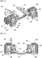
- FIGS. 3 to 6 show a preferred embodiment in different views, for reasons of clarity only in figure 4 the at least one device 38 with the optional housing 40 and the at least one optional device 46 with the housing 48 are shown schematically.
- the brackets 34, 42 respectively support the outer trim pieces 26('), 28(') (and 30(') - not shown).
- the outer lining part 26 embodied as a fender cover is fastened to an outermost fastening section 50 of the carrier 34 with respect to the transverse axis Q.
- the outer lining part 28 embodied as a fender wheel shell is fastened to a fastening section 52 of the carrier 34 .
- the attachment section 52 can be attached to an upper side of the carrier 34 and/or to a front side (with respect to the longitudinal axis L of the vehicle frame) of the carrier 34 .
- a spray guard or a spray guard flap 56 can optionally be fastened to the outer lining part 28 and is therefore preferably also carried by the carrier 34 .
- an attachment portion 54 of the bracket 34 is also attached to an outer side of the main side member 20 .
- the material recess 36 or the at least one device 38 can preferably be arranged in the carrier 34 between and/or at a distance from the fastening sections 50, 52 and/or 54.
- the further carrier 42 is configured at least in principle in accordance with the carrier 34, preferably with regard to the attachment sections 50, 52 and 54, the carrier 34 preferably being attached to an outer side of the main longitudinal member 22.
- the material recess 36 is preferably delimited by a completely circumferential edge of the carrier 34 .
- the edge can have one or more fastening projections 58 (e.g. fastening lugs) (for reasons of clarity only in figure 4 provided with reference numbers).
- the at least one device 38 preferably the housing 40 of the device 38, can be fastened to the fastening projections 58, for example by means of screw connections.
- the at least one fastening projection can be directed toward an interior of the material recess 36 and/or be flattened or plate-shaped.
- the outer paneling part 28 can be attached to the one or more attachment projections 58 .
- the invention is not limited to the preferred embodiments described above. Rather, a large number of variants and modifications are possible, which also make use of the idea of the invention and therefore fall within the scope of protection.
- the invention also claims protection for the subject matter and the features of the subclaims independently of the claims referred to.
- the individual features of independent claim 1 are each disclosed independently of one another.
- the features of the dependent claims are also independent of all features of independent claim 1 and, for example, independent of the features relating to the presence and/or the configuration of the vehicle frame, the at least one outer trim part, the carrier and/or the at least one device of independent claim 1 disclosed. All ranges herein are to be understood as disclosed such that all values falling within each range are disclosed individually, e.g. B. also as the respective preferred narrower outer limits of the respective area.
Landscapes
- Engineering & Computer Science (AREA)
- Chemical & Material Sciences (AREA)
- Combustion & Propulsion (AREA)
- Transportation (AREA)
- Mechanical Engineering (AREA)
- Body Structure For Vehicles (AREA)
Applications Claiming Priority (1)
| Application Number | Priority Date | Filing Date | Title |
|---|---|---|---|
| DE102021127607.1A DE102021127607A1 (de) | 2021-10-25 | 2021-10-25 | Träger für ein Außenverkleidungsteil |
Publications (1)
| Publication Number | Publication Date |
|---|---|
| EP4169813A1 true EP4169813A1 (fr) | 2023-04-26 |
Family
ID=83693140
Family Applications (1)
| Application Number | Title | Priority Date | Filing Date |
|---|---|---|---|
| EP22201611.5A Pending EP4169813A1 (fr) | 2021-10-25 | 2022-10-14 | Support pour un élément de garniture extérieure |
Country Status (2)
| Country | Link |
|---|---|
| EP (1) | EP4169813A1 (fr) |
| DE (1) | DE102021127607A1 (fr) |
Citations (7)
| Publication number | Priority date | Publication date | Assignee | Title |
|---|---|---|---|---|
| DE4203061A1 (de) * | 1992-02-04 | 1993-08-19 | Daimler Benz Ag | Rahmenseitige einspannung eines halterohres fuer die schlussleuchten und/oder die kotfluegel eines lkw's oder eines anhaengers |
| DE4435549C1 (de) * | 1994-10-05 | 1996-05-15 | Daimler Benz Ag | Gehäuseträgeranordnung, insbesondere von Nutzfahrzeug-Elektronikgehäusen |
| DE102010025260A1 (de) * | 2010-06-26 | 2011-12-29 | Man Truck & Bus Ag | Traggestell zur seitlichen Befestigung von Anbauteilen an einem Längsträger einer Nutzfahrzeug-Tragstruktur |
| EP3571065A1 (fr) * | 2017-01-19 | 2019-11-27 | Equalaire Systems, Inc. | Système de gonflage de pneu monté à l'extérieur |
| EP3616956A1 (fr) | 2018-08-30 | 2020-03-04 | MAN Truck & Bus SE | Module énergétique pour un véhicule utilitaire |
| EP3626497A2 (fr) | 2018-08-30 | 2020-03-25 | MAN Truck & Bus SE | Véhicule utilitaire modulaire |
| CN111516760A (zh) * | 2020-04-27 | 2020-08-11 | 东风柳州汽车有限公司 | 挡泥板装置 |
Family Cites Families (3)
| Publication number | Priority date | Publication date | Assignee | Title |
|---|---|---|---|---|
| DE4041016C1 (fr) | 1990-12-20 | 1992-07-16 | Audi Ag, 8070 Ingolstadt, De | |
| DE4309100C2 (de) | 1993-03-22 | 1998-05-07 | Daimler Benz Ag | Seitenverkleidung für Nutzfahrzeuge |
| DE102021003966A1 (de) | 2021-08-02 | 2021-09-16 | Daimler Ag | Modulares Energieversorgungssystem für ein elektrisch angetriebenes Fahrzeug und Energiemodul für ein modulares Energieversorgungssystem |
-
2021
- 2021-10-25 DE DE102021127607.1A patent/DE102021127607A1/de active Pending
-
2022
- 2022-10-14 EP EP22201611.5A patent/EP4169813A1/fr active Pending
Patent Citations (7)
| Publication number | Priority date | Publication date | Assignee | Title |
|---|---|---|---|---|
| DE4203061A1 (de) * | 1992-02-04 | 1993-08-19 | Daimler Benz Ag | Rahmenseitige einspannung eines halterohres fuer die schlussleuchten und/oder die kotfluegel eines lkw's oder eines anhaengers |
| DE4435549C1 (de) * | 1994-10-05 | 1996-05-15 | Daimler Benz Ag | Gehäuseträgeranordnung, insbesondere von Nutzfahrzeug-Elektronikgehäusen |
| DE102010025260A1 (de) * | 2010-06-26 | 2011-12-29 | Man Truck & Bus Ag | Traggestell zur seitlichen Befestigung von Anbauteilen an einem Längsträger einer Nutzfahrzeug-Tragstruktur |
| EP3571065A1 (fr) * | 2017-01-19 | 2019-11-27 | Equalaire Systems, Inc. | Système de gonflage de pneu monté à l'extérieur |
| EP3616956A1 (fr) | 2018-08-30 | 2020-03-04 | MAN Truck & Bus SE | Module énergétique pour un véhicule utilitaire |
| EP3626497A2 (fr) | 2018-08-30 | 2020-03-25 | MAN Truck & Bus SE | Véhicule utilitaire modulaire |
| CN111516760A (zh) * | 2020-04-27 | 2020-08-11 | 东风柳州汽车有限公司 | 挡泥板装置 |
Also Published As
| Publication number | Publication date |
|---|---|
| DE102021127607A1 (de) | 2023-04-27 |
Similar Documents
| Publication | Publication Date | Title |
|---|---|---|
| DE102010007414B4 (de) | Einbaumodul für ein Hybridfahrzeug | |
| DE112011101856B4 (de) | Fahrzeugladegerät-Montagestruktur | |
| EP4200195B1 (fr) | Groupe de véhicules automobiles | |
| DE112019004338T5 (de) | Batteriepaket-anordnungsstruktur | |
| DE112007001145B4 (de) | Speichervorrichtung | |
| DE102020200394A1 (de) | Fahrzeug | |
| EP3862205A1 (fr) | Véhicule articulé fonctionnant sur batterie électrique | |
| EP4377112A1 (fr) | Système d'assemblage modulaire servant à faire passer un système de propulsion d'un véhicule à moteur d'un moteur à combustion interne à un système de propulsion électrique, structure de support prévue à cet effet, véhicule à moteur équipé du système d'assemblage modulaire et procédé de rééquipement | |
| EP3616956B1 (fr) | Module énergétique pour un véhicule utilitaire | |
| EP3934966B1 (fr) | Dispositif de châssis pour un véhicule, notamment pour un véhicule automobile, ainsi que véhicule comprenant au moins un tel dispositif de châssis | |
| DE102016203210A1 (de) | Zumindest teilweise elektrisch betreibbares Kraftfahrzeug | |
| EP3616954B1 (fr) | Poids lourd doté d'une unité d'entraînement électrique | |
| EP4169813A1 (fr) | Support pour un élément de garniture extérieure | |
| DE102021127621A1 (de) | Crashstruktur für Energiespeicher | |
| EP4169773A1 (fr) | Dispositif d'inclinaison d'un véhicule automobile | |
| DE102022107521B4 (de) | Fahrzeug mit einem in einer Lenksäule angeordneten Heizstrahler | |
| EP4173864A1 (fr) | Structure de revêtement latéral et de collision pour accumulateur d'énergie d'un véhicule automobile | |
| DE102011121517A1 (de) | Kabelbaumanordnungsstruktur eines Fahrzeugs | |
| DE102021006775B4 (de) | Nutzfahrzeug mit Ladesteckdose | |
| DE102021127616B4 (de) | Nutzfahrzeug mit Ladesteckdose | |
| DE102021006771B4 (de) | Nutzfahrzeug mit Ladesteckdose | |
| DE102021006770B4 (de) | Nutzfahrzeug mit Ladesteckdose | |
| DE102021006773B4 (de) | Nutzfahrzeug mit Ladesteckdose | |
| DE102021006774B4 (de) | Nutzfahrzeug mit Ladesteckdose | |
| DE102021006776B4 (de) | Nutzfahrzeug mit Ladesteckdose |
Legal Events
| Date | Code | Title | Description |
|---|---|---|---|
| PUAI | Public reference made under article 153(3) epc to a published international application that has entered the european phase |
Free format text: ORIGINAL CODE: 0009012 |
|
| STAA | Information on the status of an ep patent application or granted ep patent |
Free format text: STATUS: THE APPLICATION HAS BEEN PUBLISHED |
|
| AK | Designated contracting states |
Kind code of ref document: A1 Designated state(s): AL AT BE BG CH CY CZ DE DK EE ES FI FR GB GR HR HU IE IS IT LI LT LU LV MC ME MK MT NL NO PL PT RO RS SE SI SK SM TR |
|
| STAA | Information on the status of an ep patent application or granted ep patent |
Free format text: STATUS: REQUEST FOR EXAMINATION WAS MADE |
|
| 17P | Request for examination filed |
Effective date: 20231024 |
|
| RBV | Designated contracting states (corrected) |
Designated state(s): AL AT BE BG CH CY CZ DE DK EE ES FI FR GB GR HR HU IE IS IT LI LT LU LV MC ME MK MT NL NO PL PT RO RS SE SI SK SM TR |
|
| STAA | Information on the status of an ep patent application or granted ep patent |
Free format text: STATUS: EXAMINATION IS IN PROGRESS |
|
| 17Q | First examination report despatched |
Effective date: 20250424 |