EP4169829B1 - Système de navigation pour bateau - Google Patents
Système de navigation pour bateau Download PDFInfo
- Publication number
- EP4169829B1 EP4169829B1 EP22202388.9A EP22202388A EP4169829B1 EP 4169829 B1 EP4169829 B1 EP 4169829B1 EP 22202388 A EP22202388 A EP 22202388A EP 4169829 B1 EP4169829 B1 EP 4169829B1
- Authority
- EP
- European Patent Office
- Prior art keywords
- furling
- sail
- mast
- cylinders
- boat
- Prior art date
- Legal status (The legal status is an assumption and is not a legal conclusion. Google has not performed a legal analysis and makes no representation as to the accuracy of the status listed.)
- Active
Links
Images





Classifications
-
- B—PERFORMING OPERATIONS; TRANSPORTING
- B63—SHIPS OR OTHER WATERBORNE VESSELS; RELATED EQUIPMENT
- B63H—MARINE PROPULSION OR STEERING
- B63H9/00—Marine propulsion provided directly by wind power
- B63H9/04—Marine propulsion provided directly by wind power using sails or like wind-catching surfaces
- B63H9/08—Connections of sails to masts, spars, or the like
- B63H9/10—Running rigging, e.g. reefing equipment
- B63H9/1021—Reefing
- B63H9/1042—Reefing by furling around or inside the boom
-
- B—PERFORMING OPERATIONS; TRANSPORTING
- B63—SHIPS OR OTHER WATERBORNE VESSELS; RELATED EQUIPMENT
- B63B—SHIPS OR OTHER WATERBORNE VESSELS; EQUIPMENT FOR SHIPPING
- B63B15/00—Superstructures, deckhouses, wheelhouses or the like; Arrangements or adaptations of masts or spars, e.g. bowsprits
- B63B2015/0016—Masts characterized by mast configuration or construction
- B63B2015/0041—Telescoping masts
-
- B—PERFORMING OPERATIONS; TRANSPORTING
- B63—SHIPS OR OTHER WATERBORNE VESSELS; RELATED EQUIPMENT
- B63H—MARINE PROPULSION OR STEERING
- B63H9/00—Marine propulsion provided directly by wind power
- B63H9/04—Marine propulsion provided directly by wind power using sails or like wind-catching surfaces
- B63H9/08—Connections of sails to masts, spars, or the like
- B63H2009/082—Booms, or the like
-
- B—PERFORMING OPERATIONS; TRANSPORTING
- B63—SHIPS OR OTHER WATERBORNE VESSELS; RELATED EQUIPMENT
- B63H—MARINE PROPULSION OR STEERING
- B63H9/00—Marine propulsion provided directly by wind power
- B63H9/04—Marine propulsion provided directly by wind power using sails or like wind-catching surfaces
- B63H9/08—Connections of sails to masts, spars, or the like
- B63H9/10—Running rigging, e.g. reefing equipment
- B63H9/1021—Reefing
- B63H2009/105—Reefing using drives for actuating reefing mechanism, e.g. roll reefing drives
Definitions
- This invention generally relates to boats. More specifically, it relates to a sail system to be mounted on a boat. This can be either a sailboat, a motorboat, or a vessel, for example a seagoing vessel.
- a typical sailboat has a mast along which a sail can be hoisted.
- the luff of the sail can be hoisted up along or inside the mast. This is done by means of a cord, which is also known as the mainsail halyard.
- the foot of the sail is typically attached to a boom perpendicular to the mast.
- the sail can be trimmed by adjusting the position of the boom in relation to the boat. This is done by means of a cord, also known as a sheet, which is attached to the boat and to the boom. Usually, this cord passes through a number of pulleys to apply greater force to the boom. There is usually also the option of reefing the sail. This reduces the area of the sail by lowering it, for example.
- a cord also known as a sheet
- a foresail attached to the front of the mast is also often used.
- a foresail can be hoisted by means of a cord (the foresail halyard), and trimmed by means of a cord (the foresail sheet).
- a stay is used to attach the mast to the boat.
- sailing Apart from its disadvantages, namely the complexity of operation and the mast making routes along inland waterways difficult or even impossible, sailing also has significant advantages.
- the main advantage is that it is a sustainable and environmentally friendly way of travelling.
- the present invention relates to a sail system to be mounted on a boat.
- the sail system contains:
- a curved yard in the plane perpendicular to the mast. This allows the sail to have an improved shape compared to a sail with a straight yard. Despite the yard being curved, it is still possible to furl the sail into it. This is made possible by dividing the furling system and the sail into segments. Each segment contains a furling cylinder with a straight axis of rotation and a piece of sail that can be furled around the roller with a maximum width equal to the length of the roller.
- the sail area can be reduced by sliding the telescopic mast together.
- the furling cylinders are arranged such that the projection of an angle between two adjacent furling cylinders, measured in a plane formed by the telescopic mast and one of the furling cylinders, and measured on the side closest to the other yard to which the sails are attached, is a predetermined angle smaller than 180°, and wherein the sails are cut such that they have parallel sides when unfurled.
- the yard containing the furling system contains a housing which is curved and in which the furling cylinders are arranged.
- the housing contains a slot through which the sails can slide. This slot can have rounded sides.
- the rounded sides can be pressure rollers mounted on the housing.
- it is the bottom yard, in a pair of two yards, that contains the furling system.
- the tensioning system is a motor mounted at an end of the yard with the furling system.
- the sail system contains a mast attachment for attaching the mast to the boat.
- the mast attachment is adapted to rotate the mast around its axis.
- the furling cylinders are intercoupled by a coupling capable of transferring a rotational moment from one furling cylinder to the other furling cylinder.
- This coupling may, for example, be a universal joint.
- the drive system contains a telescopic extension cylinder.
- This may be a riser cylinder.
- the telescopic extension cylinder may be hydraulically or mechanically driven.
- At least one of the sails is provided with one or more sail battens parallel to the corresponding furling cylinder.
- the present invention relates to a boat on which a sail system according to the present invention is mounted.
- the boat may additionally contain a keel which is tiltable and/or extendable.
- the present invention relates to a sail system 100 to be mounted on a boat.
- Reference numbers are used in this and the following paragraphs. These refer to the exemplary embodiments in FIG. 1 to 13 , with reference numbers being used consistently throughout the various figures.
- the sail system 100 contains:
- the yards are mounted on the mast on the side of the mast closest to the rear (stern) of the boat, such that the mast is closest to the bow.
- the mast is no longer visible (hidden behind the sail) to anyone standing at the rear of the boat.
- This is not strictly necessary.
- the arrangement of the yards and mast can also be reversed.
- the telescopic mast When manoeuvring, or sailing on inland waterways, or in strong winds, the telescopic mast can be retracted, which will reduce wind sail. Moreover, this also results in a clearance reduction, eliminating waiting times at bridges. It also makes it possible to use waterways with fixed bridges and still be able to sail. Moreover, there is no need for a stay, which means that whistling of wind through the rods and cables can be avoided. The use of ropes can also be minimised by using an extendable mast with sails furled into the yard. The time needed for rigging and unrigging can be dramatically reduced as there is no need to unpack and mount sails. All that is required is to extend the telescopic mast to the desired height. This height determines the desired sail area depending on the wind.
- the present invention relates to a boat 200 containing a sail system 100 according to any of the preceding claims.
- the boat may additionally contain a keel 170 which is tiltable and/or extendable.
- the sail system is applicable to different boat sizes. For example, it may even be applied to large seagoing vessels.
- the length may, for example, be greater than 20 m or even greater than 100 m, or more.
- a sail system according to embodiments of the present invention can, for example, be used for mounting on a motor boat so as to obtain a motor sailor. It is an advantage of embodiments of the present invention that a boat is obtained that has the convenience of a motor boat and can be propelled by the wind, thus reducing fuel consumption.
- a sail system according to embodiments of the present invention may also be installed on a shipping vessel.
- the sail protrudes from both sides of the vessel. This allows the sail area to be increased. This is particularly advantageous for the sail area close to the deck. This is because the wind force exerting pressure on this sail surface creates a propulsive force, while the torque on the boat pushing the boat at an angle is lower the lower the sail is.
- the boat contains a controller capable of controlling the position of the mast and keel depending on the inclination of the boat and on the wind.
- FIG. 1 shows an extended mast system 110 in accordance with embodiments of the present invention.
- two yards 120 are shown which are parallel to one another.
- the sails 140 are attached to the top yard and can be furled into the bottom yard.
- the mast system 100 contains a mast attachment 114 that allows the system to be mounted on a boat.
- the furling cylinders 151 are arranged such that the projection of an angle between two adjacent furling cylinders, measured in a plane formed by the telescopic mast 110 and one of the furling cylinders, and measured on the side closest to the other yard to which the sails are attached, is a predetermined angle smaller than 180°, and wherein the sails are cut such that they have parallel sides when unfurled.
- FIG. 2 which shows a schematic drawing of a sail system with the mast retracted, in accordance with embodiments of the present invention. This figure shows the housing 121 of the yard 120. A dotted straight line is also drawn to illustrate the curvature of the yard in the vertical plane.
- the furling cylinders can be positioned closer to one another without the sails obstructing one another when they are being furled. Because the projection of an angle between two adjacent furling cylinders, measured in a plane formed by the telescopic mast and one of the furling cylinders, is smaller than 180°, the angle between an upright body of the sail and a furling cylinder is smaller than 90°. This will reduce the width of the roller with the sail as more sail is furled.
- the projections of two adjacent furling cylinders in a plane perpendicular to the mast form an angle with one another that is smaller than 180°.
- the degree to which the angle is smaller than 180° is also known as the yard bulge.
- the yard bulge can be between 1° and 10°, for example between 2° and 5°, for example 3°. In the latter case, the angle between the projections of two adjacent furling cylinders in a plane perpendicular to the mast is 177°.
- the yard bulges between the different furling cylinders are not necessarily the same.
- the side roller To close the vertical gap between two sails when they are unfurled, the side roller must make an angle with the horizontal. This angle is also known as the tilt angle. This may be, for example, half the spherical angle between the two furling cylinders (central and side roller). This principle can be repeated again and again to obtain the desired width of the total sail.
- the opening between sail segments is sealed.
- the sail segments are attached to one another such that when unfurled they form a tight unit together.
- sail segments can be provided between the segments that are shaped so that when unfurled, they form a tight unit together with the other segments.
- these sail pieces between the segments may be made of stretchable material. It is an advantage of embodiments of the present invention that the various sail segments are attached to one another and form a tight unit. This enables smooth wind circulation in front of and behind the sail. Since there are no gaps between the segments, the wind cannot pass between two segments from one side of the sail to the other. This also allows a pressure difference to build up between the front and rear of the sail, which increases the force of the sail on the boat.
- the yard 120 containing the furling system 150 contains a housing 121 which is curved and in which the furling cylinders 151 are arranged, wherein the housing contains a slot through which the sails 140 can slide. It is an advantage of embodiments of the present invention that the furling cylinders can be positioned in the housing.
- FIG. 3 two yards and a mast are shown in the retracted state.
- the housing 121 of the yards is indicated in this figure. When this mast is extended, the yards will also move apart and the sails will unwind.
- the slot has rounded sides 152.
- An example of this is shown in the schematic drawing in FIG. 4 .
- This figure shows that the slot is provided with two rollers which prevent the sail with furling cylinder from coming out of the yard support structure. These segments are then joined together to form an arch with only the central segment attached to the mast.
- a structure 155 is also present on the yard, which structure can be used to attach the yard to the mast.
- the structure is present centrally, on the concave side of the yard.
- the invention is not limited thereto, however.
- the attachment structure may also be present at other locations on the yard.
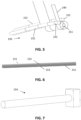
- the rounded sides are pressure rollers 152 mounted on the housing. An example of this is shown in FIG. 5 . However, the housing itself is not drawn in order to clearly show the pressure rollers 152 and the furling cylinders 151.
- the pressure rollers 152 can be bearing mounted or fixed.
- the sail can furl/unfurl from the furling cylinder 151, which, in embodiments of the present invention, is driven.
- the vertical force in the sail keeps the furling cylinders pressed against the pressure rollers. Since, in this embodiment, the furling cylinder 151 rests against the pressure rollers 151 located above it, its central axis will move depending on the amount of cloth on the roller. The drive will also experience this centre displacement. Therefore, in such an exemplary embodiment, the drive is freely arranged parallel to the centre displacement and is only secured against rotation around the central axis.
- a drive can be provided on both sides of the outermost furling cylinders. In some embodiments of the present invention, the drive can also be manual.
- the furling cylinders 151 are intercoupled by a coupling 153 capable of transferring a rotational moment from one furling cylinder to the other furling cylinder.
- This coupling may, for example, be a universal joint.
- this coupling between the furling cylinders 151 which must operate at an angle and also remain torsionally coupled, is implemented with a tongue and groove connection provided with plastic between the contact surfaces. This can be implemented in the tubes themselves. An example of this is shown in FIG. 6 .
- FIG. 9 shows a schematic drawing of a mast 110 in accordance with an exemplary embodiment of the present invention.
- the mast 110 is telescopic.
- the mast contains several mast sections that can be slid together.
- the bottom (when the mast is fully extended) telescopic mast section has the largest cross-sectional area, and the higher the telescopic mast section, the smaller the cross-sectional area of the mast section.
- the bottom telescopic mast section 111 is arranged on a mast attachment 114 which in this case is a slewing ring bearing.
- the slewing ring bearing may have, for example, internal or external toothing.
- the arrangement on the slewing ring allows the telescopic mast 110 to rotate around its axis.
- the toothing engages a pinion coupled to a gearbox in order to enable the mast to rotate by means of a motor depending on the wind and sailing direction.
- the invention is not limited to this present embodiment for rotating the mast around its axis. Embodiments other than a slewing ring with toothing are also possible.
- the overall length of the bottom telescopic mast section 111 determines the number of telescopic sections required to obtain a certain maximum length. In embodiments of the present invention, this maximum length is determined depending on the desired sail result.
- the different mast sections can be slid apart by means of a drive provided for this purpose.
- This drive may contain a telescopic extension cylinder 115a driven by a drive system 115b.
- This telescopic cylinder may be hydraulically or mechanically driven, for example.
- the telescopic cylinder may be extended using compressed air. This can reduce the weight.
- the drive for sliding the different mast sections apart may contain a single cylinder. The length of such a cylinder may, for example, be twice as long when extended than when retracted.
- a mechanical telescopic jack can be used. An example of this is shown in FIG. 11 with extension system 115a and motor 115b.
- a riser cylinder that gradually pushes the telescopic sections upwards. This is a common technique in telescopic cranes serving as lifting tools, or in telescopic handlers.
- a telescopic hydraulic cylinder can be used.
- FIG. 10 shows a top view of the same mast configuration as FIG. 9 .
- the furling system 150 contains a tensioning system 154 for tensioning the sails between the two yards.
- a tensioning system 154 for tensioning the sails between the two yards.
- the tensioning system may be a tube motor. In this case, a tube containing a motor drive unit is present. Alternatively or additionally, the tensioning system may contain a gearbox with a drive motor. In FIG. 7 , this is represented by the cubic block at the end of the tube.
- the drive is only rotationally locked against co-turning.
- the centre can slide along with the centre of the furling cylinder 151 that drives it.
- a sail system according to embodiments of the present invention can be used on large transport vessels (e.g. in commercial shipping), optionally in combination with motors. In the latter case, such a system can reduce the consumption, and consequently the emissions, of the transport vessel. It is also advantageous that in severe weather the mast can be retracted, allowing the sails to be furled into the yard. Also, when the mast is retracted, there is no obstruction in terms of clearance height or unloading and loading in the harbour.
- ballast weight can be used.
- the boat contains a keel 170 which is tiltable and/or extendable.
- the ballast weight is hinged such that it can always provide a balance with the sail pressure and thus the boat experiences no or reduced skew.
- Sailboats typically have a fixed keel with ballast weight. Motor boats do not have this.
- the ballast weight could thus be hingeably arranged for both ship types; in some cases, hinging can also be combined with retraction of the ballast weight.
- FIG. 12 A schematic drawing of such a keel 170 is shown in FIG. 12 .
- keel 170 is tiltable and telescopic.
- the tilting mechanism and the extension of the keel can be driven in several ways.
- the ballast weight hangs from a water-driven telescopic cylinder 175 that can raise the keel 170 if necessary.
- This described structure is hinged to a housing 174 which is incorporated into the bottom of the boat.
- a driven spindle 172 Above the tiltable keel 170 is a driven spindle 172 which, when rotated, angle and hold the keel with ballast.
- the drive 171 for tilting can drive the tilt drive rod 172.
- This drawn version has the option of tilting 30° to starboard and 30° to port.
- the invention is not limited thereto, however. With the housing cover 173 applied, the assembly is watertight with respect to the boat. In this example, the housing at the level of the hinge is not watertight since this complexity is not needed.
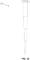
- a more detailed drawing of the extension cylinder is shown in FIG. 13 .
- FIG. 14 shows a schematically drawn side view of a boat, in accordance with embodiments of the present invention.
- the boat contains a sail system 100, and a keel 170 in accordance with embodiments of the present invention.
- This keel may be tiltable and/or extendable.
- FIG. 15 shows a schematically drawn top view of a boat, in accordance with embodiments of the present invention.
- the mast of the sail system 100 is rotatably arranged on the boat.
Landscapes
- Engineering & Computer Science (AREA)
- Life Sciences & Earth Sciences (AREA)
- Sustainable Development (AREA)
- Sustainable Energy (AREA)
- Chemical & Material Sciences (AREA)
- Combustion & Propulsion (AREA)
- Mechanical Engineering (AREA)
- Ocean & Marine Engineering (AREA)
- Wind Motors (AREA)
Claims (15)
- Un système de voile (100) à monter sur un bateau, le système de voile (100) contenant :- un mât télescopique (110) contenant au moins deux sections de mât (111) qui peuvent être glissées l'une dans l'autre et écartées, dans lequel le mât télescopique (110) contient un système d'entraînement (115) adapté pour faire glisser les sections de mât (111) ensemble et à part,- au moins deux vergues (120), avec des voiles (140) entre les deux vergues (120), montées parallèlement l'une à l'autre sur les sections de mât (111) de telle sorte que, lorsque les sections de mât (111) sont écartées, la distance entre les deux vergues (120) augmente,- caractérisé en ce que au moins une des deux vergues (120) contient un système d'enroulement (150) composé de plusieurs cylindres d'enroulement interconnectés (151), chacun ayant un axe de rotation droit autour duquel les voiles (140) peuvent être enroulées, avec une voile différente sur chaque cylindre d'enroulement, dans lequel les cylindres d'enroulement sont disposés de telle manière qu'une projection de l'ensemble des cylindres d'enroulement interconnectés dans un plan perpendiculaire au mât est convexe et dans lequel le système d'enroulement (150) contient un système de tension (154) pour tendre les voiles entre les deux vergues.
- Un système de voile (100) selon la revendication 1, dans lequel les cylindres d'enroulement (151) sont disposés de telle manière que la projection d'un angle entre deux cylindres d'enroulement adjacents, mesurée dans un plan formé par le mât télescopique (110) et l'un des cylindres d'enroulement, et mesurée du côté le plus proche de l'autre vergue à laquelle les voiles sont attachées, est un angle prédéterminé inférieur à 180°, et dans lequel les voiles sont coupées de telle manière qu'elles ont des côtés parallèles lorsqu'elles sont déroulées.
- Un système de voile (100) selon l'une quelconque des revendications précédentes, dans lequel la vergue (120) contenant le système d'enroulement (150) contient un logement (121) qui est courbé et dans lequel les cylindres d'enroulement (151) sont disposés, dans lequel le logement contient une fente à travers laquelle les voiles (140) peuvent glisser.
- Un système de voile (100) selon la revendication 3, dans lequel la fente a des côtés arrondis (152).
- Un système de voile (100) selon la revendication 4, dans lequel les côtés arrondis sont des rouleaux de pression (152) montés sur le logement.
- Un système de voile (100) selon l'une quelconque des revendications précédentes, dans lequel dans une paire de deux vergues, la vergue inférieure contient le système d'enroulement (150).
- Un système de voile (100) selon l'une quelconque des revendications précédentes, dans lequel le système de tension (154) est un moteur monté à une extrémité de la vergue avec le système d'enroulement (150).
- Un système de voile (100) selon l'une quelconque des revendications précédentes, le système de voile contenant une fixation de mât (114) pour attacher le mât (110) au bateau.
- Un système de voile (100) selon la revendication 8, dans lequel la fixation de mât (114) est adaptée pour faire tourner le mât (110) autour de son axe.
- Un système de voile (100) selon l'une quelconque des revendications précédentes, dans lequel les cylindres d'enroulement (151) sont interconnectés par un accouplement (153) capable de transférer un moment de rotation d'un cylindre d'enroulement à l'autre cylindre d'enroulement.
- Un système de voile (100) selon la revendication 9, dans lequel l'accouplement (153) est un joint universel.
- Un système de voile (100) selon l'une quelconque des revendications précédentes, dans lequel le système d'entraînement (115) contient un cylindre d'extension télescopique.
- Un système de voile (100) selon l'une quelconque des revendications précédentes, dans lequel au moins une des voiles est pourvue d'une ou plusieurs lattes de voile parallèles au cylindre d'enroulement correspondant (151).
- Un bateau contenant un système de voile (100) selon l'une quelconque des revendications précédentes.
- Un bateau selon la revendication 14, le bateau contenant en outre une quille (170) qui est inclinable et/ou extensible.
Applications Claiming Priority (1)
| Application Number | Priority Date | Filing Date | Title |
|---|---|---|---|
| BE202102823 | 2021-10-20 |
Publications (4)
| Publication Number | Publication Date |
|---|---|
| EP4169829A1 EP4169829A1 (fr) | 2023-04-26 |
| EP4169829B1 true EP4169829B1 (fr) | 2024-05-29 |
| EP4169829C0 EP4169829C0 (fr) | 2024-05-29 |
| EP4169829B8 EP4169829B8 (fr) | 2024-07-17 |
Family
ID=84367408
Family Applications (1)
| Application Number | Title | Priority Date | Filing Date |
|---|---|---|---|
| EP22202388.9A Active EP4169829B8 (fr) | 2021-10-20 | 2022-10-19 | Système de navigation pour bateau |
Country Status (1)
| Country | Link |
|---|---|
| EP (1) | EP4169829B8 (fr) |
Family Cites Families (5)
| Publication number | Priority date | Publication date | Assignee | Title |
|---|---|---|---|---|
| DE3502670A1 (de) * | 1985-01-26 | 1986-11-20 | Martin 4790 Paderborn Schatta | Motor-segelschiff mit einer segel- und kraengungsautomatik insbesondere fuer eine autarke antriebs- sowie versorgungsenergieentnahme aus wind- und sonnenkraft |
| AT504907B1 (de) * | 2007-07-10 | 2008-09-15 | Waldhauser Kurt | Rollreffbaum für segelschiffe |
| DE202011101489U1 (de) * | 2011-06-06 | 2011-10-20 | Wilhelm Debor | Teleskop-Segelmast mit einrollbaren Segeln |
| JP6439260B2 (ja) * | 2014-03-18 | 2018-12-19 | 株式会社タダノ | 硬帆船の伸縮硬帆制御方法および制御装置 |
| SI25154A (sl) * | 2017-06-08 | 2017-09-29 | MIDES DESIGN d.o.o. | Jadrovna konstrukcija |
-
2022
- 2022-10-19 EP EP22202388.9A patent/EP4169829B8/fr active Active
Also Published As
| Publication number | Publication date |
|---|---|
| EP4169829B8 (fr) | 2024-07-17 |
| EP4169829A1 (fr) | 2023-04-26 |
| EP4169829C0 (fr) | 2024-05-29 |
Similar Documents
| Publication | Publication Date | Title |
|---|---|---|
| US3132620A (en) | Sailboat | |
| US4367688A (en) | Sailboat rig | |
| EP2903890B1 (fr) | Aile rigide ouvrante | |
| JP5642716B2 (ja) | 帆を帆装する機械化装置 | |
| US4867089A (en) | Structural system for inclining sailboat masts to windward | |
| EP3317178B1 (fr) | Système de voile du type aile | |
| WO2021005420A1 (fr) | Dispositif de voile carrée télescopique | |
| US4934295A (en) | Sailing vessel | |
| US3749042A (en) | Furling and unfurling of sails | |
| AU2002236181B2 (en) | Flexible wing-sail and wind-propelled vehicle including same | |
| US7762204B2 (en) | Retractable bowsprit for a sailing vessel | |
| EP4169829A1 (fr) | Système de navigation pour bateau | |
| AU760350B2 (en) | Craft with tilting sail | |
| US4799443A (en) | Swing sail boat | |
| US5934214A (en) | Method of sailing a boat, and sailing vessel | |
| US4499841A (en) | Sail rigging and control system | |
| WO2020234456A1 (fr) | Voile | |
| US5088431A (en) | Sailing vessels | |
| BE1029865B1 (nl) | Zeilsysteem voor een boot | |
| US20240270360A1 (en) | Sail propulsion element, sail-propelled vehicle | |
| US20210031883A1 (en) | Watercraft having a wind-powered drive unit | |
| US10040529B1 (en) | Simplified sailing rig | |
| US20240270361A1 (en) | Sail propulsion element, sail-propelled vehicle | |
| KR101254627B1 (ko) | 요트용 높이조절장치 | |
| WO2020075876A1 (fr) | Voilier |
Legal Events
| Date | Code | Title | Description |
|---|---|---|---|
| PUAI | Public reference made under article 153(3) epc to a published international application that has entered the european phase |
Free format text: ORIGINAL CODE: 0009012 |
|
| STAA | Information on the status of an ep patent application or granted ep patent |
Free format text: STATUS: THE APPLICATION HAS BEEN PUBLISHED |
|
| AK | Designated contracting states |
Kind code of ref document: A1 Designated state(s): AL AT BE BG CH CY CZ DE DK EE ES FI FR GB GR HR HU IE IS IT LI LT LU LV MC ME MK MT NL NO PL PT RO RS SE SI SK SM TR |
|
| STAA | Information on the status of an ep patent application or granted ep patent |
Free format text: STATUS: REQUEST FOR EXAMINATION WAS MADE |
|
| 17P | Request for examination filed |
Effective date: 20230710 |
|
| RBV | Designated contracting states (corrected) |
Designated state(s): AL AT BE BG CH CY CZ DE DK EE ES FI FR GB GR HR HU IE IS IT LI LT LU LV MC ME MK MT NL NO PL PT RO RS SE SI SK SM TR |
|
| GRAP | Despatch of communication of intention to grant a patent |
Free format text: ORIGINAL CODE: EPIDOSNIGR1 |
|
| STAA | Information on the status of an ep patent application or granted ep patent |
Free format text: STATUS: GRANT OF PATENT IS INTENDED |
|
| INTG | Intention to grant announced |
Effective date: 20240208 |
|
| GRAS | Grant fee paid |
Free format text: ORIGINAL CODE: EPIDOSNIGR3 |
|
| GRAA | (expected) grant |
Free format text: ORIGINAL CODE: 0009210 |
|
| STAA | Information on the status of an ep patent application or granted ep patent |
Free format text: STATUS: THE PATENT HAS BEEN GRANTED |
|
| AK | Designated contracting states |
Kind code of ref document: B1 Designated state(s): AL AT BE BG CH CY CZ DE DK EE ES FI FR GB GR HR HU IE IS IT LI LT LU LV MC ME MK MT NL NO PL PT RO RS SE SI SK SM TR |
|
| REG | Reference to a national code |
Ref country code: CH Ref legal event code: EP |
|
| GRAT | Correction requested after decision to grant or after decision to maintain patent in amended form |
Free format text: ORIGINAL CODE: EPIDOSNCDEC |
|
| REG | Reference to a national code |
Ref country code: CH Ref legal event code: PK Free format text: BERICHTIGUNGEN |
|
| REG | Reference to a national code |
Ref country code: IE Ref legal event code: FG4D |
|
| REG | Reference to a national code |
Ref country code: DE Ref legal event code: R096 Ref document number: 602022003686 Country of ref document: DE |
|
| REG | Reference to a national code |
Ref country code: CH Ref legal event code: PK Free format text: BERICHTIGUNG B8 |
|
| RAP4 | Party data changed (patent owner data changed or rights of a patent transferred) |
Owner name: DE MAEYER, MARC |
|
| RIN2 | Information on inventor provided after grant (corrected) |
Inventor name: DE MAEYER, MARC |
|
| U01 | Request for unitary effect filed |
Effective date: 20240604 |
|
| U07 | Unitary effect registered |
Designated state(s): AT BE BG DE DK EE FI FR IT LT LU LV MT NL PT SE SI Effective date: 20240614 |
|
| PG25 | Lapsed in a contracting state [announced via postgrant information from national office to epo] |
Ref country code: IS Free format text: LAPSE BECAUSE OF FAILURE TO SUBMIT A TRANSLATION OF THE DESCRIPTION OR TO PAY THE FEE WITHIN THE PRESCRIBED TIME-LIMIT Effective date: 20240929 |
|
| PG25 | Lapsed in a contracting state [announced via postgrant information from national office to epo] |
Ref country code: HR Free format text: LAPSE BECAUSE OF FAILURE TO SUBMIT A TRANSLATION OF THE DESCRIPTION OR TO PAY THE FEE WITHIN THE PRESCRIBED TIME-LIMIT Effective date: 20240529 |
|
| PG25 | Lapsed in a contracting state [announced via postgrant information from national office to epo] |
Ref country code: GR Free format text: LAPSE BECAUSE OF FAILURE TO SUBMIT A TRANSLATION OF THE DESCRIPTION OR TO PAY THE FEE WITHIN THE PRESCRIBED TIME-LIMIT Effective date: 20240830 |
|
| PG25 | Lapsed in a contracting state [announced via postgrant information from national office to epo] |
Ref country code: ES Free format text: LAPSE BECAUSE OF FAILURE TO SUBMIT A TRANSLATION OF THE DESCRIPTION OR TO PAY THE FEE WITHIN THE PRESCRIBED TIME-LIMIT Effective date: 20240529 |
|
| PG25 | Lapsed in a contracting state [announced via postgrant information from national office to epo] |
Ref country code: PL Free format text: LAPSE BECAUSE OF FAILURE TO SUBMIT A TRANSLATION OF THE DESCRIPTION OR TO PAY THE FEE WITHIN THE PRESCRIBED TIME-LIMIT Effective date: 20240529 |
|
| PG25 | Lapsed in a contracting state [announced via postgrant information from national office to epo] |
Ref country code: PL Free format text: LAPSE BECAUSE OF FAILURE TO SUBMIT A TRANSLATION OF THE DESCRIPTION OR TO PAY THE FEE WITHIN THE PRESCRIBED TIME-LIMIT Effective date: 20240529 Ref country code: NO Free format text: LAPSE BECAUSE OF FAILURE TO SUBMIT A TRANSLATION OF THE DESCRIPTION OR TO PAY THE FEE WITHIN THE PRESCRIBED TIME-LIMIT Effective date: 20240829 Ref country code: IS Free format text: LAPSE BECAUSE OF FAILURE TO SUBMIT A TRANSLATION OF THE DESCRIPTION OR TO PAY THE FEE WITHIN THE PRESCRIBED TIME-LIMIT Effective date: 20240929 Ref country code: HR Free format text: LAPSE BECAUSE OF FAILURE TO SUBMIT A TRANSLATION OF THE DESCRIPTION OR TO PAY THE FEE WITHIN THE PRESCRIBED TIME-LIMIT Effective date: 20240529 Ref country code: GR Free format text: LAPSE BECAUSE OF FAILURE TO SUBMIT A TRANSLATION OF THE DESCRIPTION OR TO PAY THE FEE WITHIN THE PRESCRIBED TIME-LIMIT Effective date: 20240830 Ref country code: ES Free format text: LAPSE BECAUSE OF FAILURE TO SUBMIT A TRANSLATION OF THE DESCRIPTION OR TO PAY THE FEE WITHIN THE PRESCRIBED TIME-LIMIT Effective date: 20240529 Ref country code: RS Free format text: LAPSE BECAUSE OF FAILURE TO SUBMIT A TRANSLATION OF THE DESCRIPTION OR TO PAY THE FEE WITHIN THE PRESCRIBED TIME-LIMIT Effective date: 20240829 |
|
| U20 | Renewal fee for the european patent with unitary effect paid |
Year of fee payment: 3 Effective date: 20241025 |
|
| PG25 | Lapsed in a contracting state [announced via postgrant information from national office to epo] |
Ref country code: CZ Free format text: LAPSE BECAUSE OF FAILURE TO SUBMIT A TRANSLATION OF THE DESCRIPTION OR TO PAY THE FEE WITHIN THE PRESCRIBED TIME-LIMIT Effective date: 20240529 |
|
| PG25 | Lapsed in a contracting state [announced via postgrant information from national office to epo] |
Ref country code: RO Free format text: LAPSE BECAUSE OF FAILURE TO SUBMIT A TRANSLATION OF THE DESCRIPTION OR TO PAY THE FEE WITHIN THE PRESCRIBED TIME-LIMIT Effective date: 20240529 Ref country code: SK Free format text: LAPSE BECAUSE OF FAILURE TO SUBMIT A TRANSLATION OF THE DESCRIPTION OR TO PAY THE FEE WITHIN THE PRESCRIBED TIME-LIMIT Effective date: 20240529 |
|
| PG25 | Lapsed in a contracting state [announced via postgrant information from national office to epo] |
Ref country code: SM Free format text: LAPSE BECAUSE OF FAILURE TO SUBMIT A TRANSLATION OF THE DESCRIPTION OR TO PAY THE FEE WITHIN THE PRESCRIBED TIME-LIMIT Effective date: 20240529 |
|
| PG25 | Lapsed in a contracting state [announced via postgrant information from national office to epo] |
Ref country code: SM Free format text: LAPSE BECAUSE OF FAILURE TO SUBMIT A TRANSLATION OF THE DESCRIPTION OR TO PAY THE FEE WITHIN THE PRESCRIBED TIME-LIMIT Effective date: 20240529 Ref country code: SK Free format text: LAPSE BECAUSE OF FAILURE TO SUBMIT A TRANSLATION OF THE DESCRIPTION OR TO PAY THE FEE WITHIN THE PRESCRIBED TIME-LIMIT Effective date: 20240529 Ref country code: RO Free format text: LAPSE BECAUSE OF FAILURE TO SUBMIT A TRANSLATION OF THE DESCRIPTION OR TO PAY THE FEE WITHIN THE PRESCRIBED TIME-LIMIT Effective date: 20240529 Ref country code: CZ Free format text: LAPSE BECAUSE OF FAILURE TO SUBMIT A TRANSLATION OF THE DESCRIPTION OR TO PAY THE FEE WITHIN THE PRESCRIBED TIME-LIMIT Effective date: 20240529 |
|
| PLBE | No opposition filed within time limit |
Free format text: ORIGINAL CODE: 0009261 |
|
| STAA | Information on the status of an ep patent application or granted ep patent |
Free format text: STATUS: NO OPPOSITION FILED WITHIN TIME LIMIT |
|
| 26N | No opposition filed |
Effective date: 20250303 |
|
| PG25 | Lapsed in a contracting state [announced via postgrant information from national office to epo] |
Ref country code: MC Free format text: LAPSE BECAUSE OF FAILURE TO SUBMIT A TRANSLATION OF THE DESCRIPTION OR TO PAY THE FEE WITHIN THE PRESCRIBED TIME-LIMIT Effective date: 20240529 |
|
| PG25 | Lapsed in a contracting state [announced via postgrant information from national office to epo] |
Ref country code: IE Free format text: LAPSE BECAUSE OF NON-PAYMENT OF DUE FEES Effective date: 20241019 |
|
| U20 | Renewal fee for the european patent with unitary effect paid |
Year of fee payment: 4 Effective date: 20251028 |
|
| PG25 | Lapsed in a contracting state [announced via postgrant information from national office to epo] |
Ref country code: CY Free format text: LAPSE BECAUSE OF FAILURE TO SUBMIT A TRANSLATION OF THE DESCRIPTION OR TO PAY THE FEE WITHIN THE PRESCRIBED TIME-LIMIT; INVALID AB INITIO Effective date: 20221019 |
|
| PG25 | Lapsed in a contracting state [announced via postgrant information from national office to epo] |
Ref country code: HU Free format text: LAPSE BECAUSE OF FAILURE TO SUBMIT A TRANSLATION OF THE DESCRIPTION OR TO PAY THE FEE WITHIN THE PRESCRIBED TIME-LIMIT; INVALID AB INITIO Effective date: 20221019 |