EP4170101A1 - Engin de chantier - Google Patents
Engin de chantier Download PDFInfo
- Publication number
- EP4170101A1 EP4170101A1 EP21848677.7A EP21848677A EP4170101A1 EP 4170101 A1 EP4170101 A1 EP 4170101A1 EP 21848677 A EP21848677 A EP 21848677A EP 4170101 A1 EP4170101 A1 EP 4170101A1
- Authority
- EP
- European Patent Office
- Prior art keywords
- acceleration
- deceleration
- manipulation
- evaluation value
- data
- Prior art date
- Legal status (The legal status is an assumption and is not a legal conclusion. Google has not performed a legal analysis and makes no representation as to the accuracy of the status listed.)
- Granted
Links
Images





Classifications
-
- E—FIXED CONSTRUCTIONS
- E02—HYDRAULIC ENGINEERING; FOUNDATIONS; SOIL SHIFTING
- E02F—DREDGING; SOIL-SHIFTING
- E02F9/00—Component parts of dredgers or soil-shifting machines, not restricted to one of the kinds covered by groups E02F3/00 - E02F7/00
- E02F9/26—Indicating devices
- E02F9/264—Sensors and their calibration for indicating the position of the work tool
-
- E—FIXED CONSTRUCTIONS
- E02—HYDRAULIC ENGINEERING; FOUNDATIONS; SOIL SHIFTING
- E02F—DREDGING; SOIL-SHIFTING
- E02F9/00—Component parts of dredgers or soil-shifting machines, not restricted to one of the kinds covered by groups E02F3/00 - E02F7/00
- E02F9/26—Indicating devices
-
- E—FIXED CONSTRUCTIONS
- E02—HYDRAULIC ENGINEERING; FOUNDATIONS; SOIL SHIFTING
- E02F—DREDGING; SOIL-SHIFTING
- E02F3/00—Dredgers; Soil-shifting machines
- E02F3/04—Dredgers; Soil-shifting machines mechanically-driven
- E02F3/28—Dredgers; Soil-shifting machines mechanically-driven with digging tools mounted on a dipper- or bucket-arm, i.e. there is either one arm or a pair of arms, e.g. dippers, buckets
- E02F3/36—Component parts
- E02F3/42—Drives for dippers, buckets, dipper-arms or bucket-arms
- E02F3/43—Control of dipper or bucket position; Control of sequence of drive operations
- E02F3/435—Control of dipper or bucket position; Control of sequence of drive operations for dipper-arms, backhoes or the like
Definitions
- the present invention relates to a construction machine, and more specifically, relates to a construction machine for supporting a specific manipulation in association with a manipulation type of an operator.
- Patent Literature 1 A system of evaluating operation data by collecting predetermined operation data of an operator and comparing the collected operation data with reference data (data of a skilled operator) has been conventionally proposed in a field of a construction machine (e.g., Patent Literature 1).
- the technology described in Patent Literature 1 enables the operator to recognize an operation result about a predetermined manipulation.
- operators to be evaluated for such an operation include some who are cautious and others who are aggressive about a certain manipulation of the construction machine. Therefore, evaluation without considering any manipulation type of an operator to be evaluated for the manipulation may result in giving useless advice to the operator.
- Patent Literature 1 executes exclusive evaluation for all the operators without consideration of the manipulation type of each operator. Hence, there is a possibility that advice given to a certain operator after evaluation of a manipulation executed by the certain operator is unsuitable for the operator, and thus the manipulation is not appropriately supported.
- Patent Literature 1 Japanese Unexamined Patent Publication No. 2009-235833
- the present invention has an object of providing a construction machine for appropriately supporting a specific manipulation by an operator in association with a manipulation type of the operator.
- a construction machine includes: an operation data acquisition part that acquires operation data about a specific manipulation by an operator: an acceleration and deceleration data specifying part that specifies acceleration data being operation data in an acceleration period and deceleration data being operation data in a deceleration period among the operation data; an evaluation data acquisition part that acquires acceleration evaluation data for evaluating the acceleration data, and deceleration evaluation data for evaluating the deceleration data; an evaluation value calculation part that calculates, on the basis of the acceleration data and the acceleration evaluation data, an acceleration evaluation value indicating a skill of the operator in the acceleration period, and calculates, on the basis of the deceleration data and the deceleration evaluation data, a deceleration evaluation value indicating a skill of the operator in the deceleration period; a manipulation type determination part that determines, on the basis of the acceleration evaluation value and the deceleration evaluation value, a manipulation type of the operator; and a notification part that gives notification of support information associated with the manipulation type
- the manipulation type of the operator is determined on the basis of the acceleration evaluation value and the deceleration evaluation value, and the support information associated with the manipulation type is notified to the operator. Therefore, a specific manipulation by the operator is appropriately supported in association with the manipulation type of the operator.
- FIG. 1 A construction machine according to an embodiment of the present invention will be described with reference to Fig. 1 to Fig. 7 .
- a hydraulic excavator 1 (see Fig. 1 ) serving as an example of a construction machine will be described.
- the hydraulic excavator 1 has manipulation support operability mounted thereon for supporting a specific manipulation by an operator.
- a manipulation of raising a boom and suspending the boom at a predetermined position (hereinafter, simply referred to "boom raising and suspending manipulation" as well) is described as an example of the specific manipulation.
- the boom is an example of a manipulation target.
- the hydraulic excavator 1 includes a lower traveling body 2 and an upper slewing body 3 slewably mounted on the lower traveling body 2.
- the upper slewing body 3 is provided with an attachment 4 and a cab 5.
- the attachment 4 includes a boom 41, an arm 42, a bucket 43, and hydraulic cylinders 44 (actuators) respectively driving these components.
- the boom 41 is rotatably supported on a front portion of the upper slewing body 3, the arm 42 is rotatably supported at a distal end of the boom 41, and the bucket 43 is rotatably supported at a distal end of the arm 42.
- the boom 41, the arm 42, and the bucket 43 are rotated under the control of operations by the corresponding hydraulic cylinders 44.
- the cab 5 includes an operator compartment arranged on the front portion of the upper slewing body 3.
- the hydraulic excavator 1 is operated by an operator having got in the cab 5.
- the cab 5 has, in the inside thereof, a seat to allow the operator to sit thereon.
- An unillustrated manipulation lever is provided on each of the right and the left sides of the seat.
- Each of the left and right manipulation levers includes a manipulation part for regulating action of each hydraulic cylinder 44 and an unillustrated slewing motor, and is swingingly shifted by the operator forward, backward, leftward, and rightward.
- the upper slewing body 3 slews and the boom 41 and other components rotate in a direction agreeing with an actuation direction of each of the left and right manipulation levers in accordance with an actuation amount of each of the levers.
- the cab 5 further includes, in the inside thereof, input and output devices, such as unillustrated various manipulation switches and a monitor 83 (see Fig. 2 ), in addition to the left and right manipulation levers.
- the monitor 83 is an example of a display part in the present invention.
- the hydraulic excavator 1 includes a controller 6 configured by hardware like a CPU and a memory, and software like a control program mounted on the hardware.
- the controller 6 is electrically connected to a storage device 7, a sensor 81, a lever meter 82, the monitor 83, and a manipulation lever 84.
- the manipulation lever 84 allows the operator to execute manipulation to the manipulation target. Examples of the manipulation target include: a working device including the boom 41, the arm 42, and the bucket 43; the upper slewing body 3; and the lower traveling body 2.
- the sensor 81 is attached to each hydraulic cylinder 44 to detect a speed of extension and contraction of the hydraulic cylinder 44 as an actual speed S a (t).
- the actual speed Sa(t) is detected by the sensor 81 at a predetermined interval (sampling interval) and input to the controller 6.
- the lever meter 82 is attached to the manipulation lever 84.
- the lever meter 82 detects an actuation amount U(t) of the manipulation lever 84.
- the actuation amount U(t) is detected by the lever meter 82 at a predetermined interval (sampling interval) and input to the controller 6.
- the manipulation lever 84 is formed of a hydraulic manipulation lever
- the lever meter 82 includes a pressure sensor for detecting a pilot pressure.
- the lever meter 82 includes a potentiometer.
- the controller 6 operatively includes an operation data acquisition part 61, an acceleration and deceleration data specifying part 62, an evaluation data acquisition part 63, an evaluation value calculation part 64, a manipulation type determination part 65, and a display control part 66.
- Each of the operation data acquisition part 61 to the display control part 66 may include a dedicated electronic circuit, such as an ASIC.
- the operation data acquisition part 61 acquires operation data (which will be described later) about a specific manipulation executed by an operator to be evaluated.
- the acceleration and deceleration data specifying part 62 specifies acceleration data being operation data in an acceleration period of the manipulation target and deceleration data being operation data in a deceleration period of the manipulation target among the operation data.
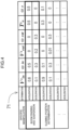
- the evaluation data acquisition part 63 acquires acceleration evaluation data for evaluating the acceleration data and deceleration evaluation data for evaluating the deceleration data with reference to an evaluation reference table 71 (see Fig. 4 ).
- the evaluation value calculation part 64 calculates, on the basis of the acceleration data and the acceleration evaluation data, an acceleration evaluation value Ea, and calculates, on the basis of the deceleration data and the deceleration evaluation data, a deceleration evaluation value Ed. For instance, the evaluation value calculation part 64 decreases the acceleration evaluation value Ea in accordance with an increase in a difference between the acceleration data and the acceleration evaluation data, and decreases the deceleration evaluation value Ed in accordance with an increase in a difference between the deceleration data and the deceleration evaluation data.
- the acceleration evaluation value Ea is a numeric value representing a skill of the operator in the acceleration period.
- a larger acceleration evaluation value Ea shows a higher skill of the operator.
- the deceleration evaluation value Eb is a numeric value representing a skill of the operator in the deceleration period. In the embodiment, a larger deceleration evaluation value Eb shows a higher skill of the operator.
- the manipulation type determination part 65 determines, on the basis of the acceleration evaluation value Ea and the deceleration evaluation value Ed, a manipulation type of the operator having executed the specific manipulation.
- the manipulation type determination part 65 determines the manipulation type of the operator as either an "aggressive" type or a "cautious” type. A specific way of determining the manipulation type will be described in detail later.
- the manipulation type represents characteristics of manipulation of the operator.
- the display control part 66 generates a manipulation support image including support information associated with the manipulation type and outputs the generated manipulation support image to the monitor 83.
- the display control part 66 is an example of a "notification part" in the present invention.
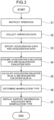
- step S1 the display control part 66 outputs an unillustrated display image showing an instruction for a start of the boom raising and suspending manipulation to the monitor 83 to instruct the operator to execute a relevant work.
- step S2 the operation data acquisition part 61 acquires operation data about the boom raising and suspending manipulation executed by the operator in accordance with the instruction for the work. Specifically, the operation data acquisition part 61 acquires the operation data including an actuation amount U(t) detected at a predetermined interval, a suspended position V out of a specific portion of the boom 41, and a raising time T o thereof.
- the actuation amount U(t) represents a value detected via the lever meter 82 at the predetermined interval (sampling interval) in the period of the boom raising and suspending manipulation.
- the suspended position V out of the specific portion of the boom 41 represents, for example, a coordinate of a position, i.e., a height position, where the distal end of the boom 41 is suspended.
- the height position where the distal end of the boom 41 is suspended is calculatable from a value of an angle sensor provided to the boom 41.
- the raising time T o represents a time in a period of acceleration from the start of manipulation to the boom 41 in the boom raising and suspending manipulation.
- the raising time T o is an example of an acceleration period value indicating a length of the acceleration period.
- step S3 the acceleration and deceleration data specifying part 62 specifies the acceleration data being operation data in the acceleration period and deceleration data being operation data in the deceleration period among the operation data acquired in step S2.
- the acceleration and deceleration data specifying part 62 specifies the data as the acceleration data when an acceleration rate ⁇ (t) calculated on the basis of the actual speed S a (t) detected by the sensor 81 is equal to or higher than 0 (acceleration rate ⁇ ⁇ 0), and specifies the data as the deceleration data when the acceleration rate is lower than 0 (acceleration rate ⁇ ⁇ 0).
- the acceleration rate ⁇ (t) is calculated on the basis of Equation 1 described below.
- Equation 1 the sign “S a (t)” denotes a speed at a present time “t”
- the sign “S a (t-1)” denotes a speed at a time that is one stage before the time "t”
- the sign “ ⁇ t” denotes an elapsed time from S a (t-1) to S a (t).
- the calculation is performed at a difference of the one stage in the embodiment, the calculation may be performed in comparison with data in a further previous stage.
- ⁇ t S a t ⁇ S a t ⁇ 1 ⁇ t
- step S4 the evaluation data acquisition part 63 acquires acceleration evaluation data and deceleration evaluation data about the boom raising and suspending manipulation with reference to the evaluation reference table 71 (see Fig. 4 ) stored in the storage device 7.
- the evaluation reference table 71 has recordation of acceleration evaluation data being operation data in an acceleration period and deceleration evaluation data being operation data in a deceleration period about a specific manipulation executed by a skilled operator in advance.
- the skilled operator has a plenty of operational experiences of the hydraulic excavator 1, for example, has a predetermined year (e.g., 10 year) or longer operational experiences.
- the sign "V s in " denotes an average or a variance of actuation amounts U(t) detected via the lever meter 82 at predetermined intervals in the acceleration period or the deceleration period.
- the sign “V s in " is an example of an actuation amount of a manipulation part by the skilled operator in the acceleration period or the deceleration period.
- the sign “V s out " denotes a position, i.e., height position, where a specific portion (distal end) of the boom 41 is suspended in the deceleration period.
- the sign “V s out " is an example of the suspended position of the manipulation target that is attained by the skilled operator in the deceleration period.
- the sign “T s o " denotes a raising time of the boom 41 in the acceleration period.
- the sign “T s o " is an example of an acceleration period value indicating a length of the acceleration period of the skilled operator.
- each of the signs " ⁇ in “, “ ⁇ out “, and “ ⁇ o " in the evaluation reference table 71 denotes a weighting parameter for use in calculating each of the acceleration evaluation value Ea and the deceleration evaluation value Ed to be described later.
- step S5 the evaluation value calculation part 64 calculates, on the basis of Equation 2 described below, the acceleration evaluation value Ea and the deceleration evaluation value Ed.
- E 100 ⁇ ⁇ in V s in ⁇ V in V s in + ⁇ out V s out ⁇ V out V s out + ⁇ o T s o ⁇ T o T s o ⁇ 100
- the evaluation value calculation part 64 obtains an average V in or a variance V in of the actuation amounts U(t) specified as the acceleration data in step S3.
- the average V in or the variance V in of the actuation amounts U(t) in the acceleration period is an example of an acceleration actuation amount indicating an amount of actuation of the manipulation part by the operator in the acceleration period.
- the average V in or the variance V in of the actuation amounts U(t) in the deceleration period is an example of a deceleration actuation amount indicating an amount of actuation of the manipulation part by the operator in the deceleration period.
- the evaluation value calculation part 64 substitutes: "V in “; “V out “ and “T o” obtained in step S2; and "V s in. “ , “V s out “, “T s o “, “ ⁇ in “, “ ⁇ out “ and “ ⁇ o " of the acceleration evaluation data acquired in step S4 for Equation 2 to calculate the acceleration evaluation value Ea.
- the evaluation value calculation part 64 decreases the acceleration evaluation value Ea in accordance with an increase in a difference (
- the evaluation value calculation part 64 obtains an average V in or a variance V in of the actuation amounts U(t) specified as the deceleration data in step S3.
- the evaluation value calculation part 64 substitutes: "V in “, “V out “ and “T o” obtained in step S2; and "V s in “, “V s out “, “T s o “, “ ⁇ in “, “ ⁇ out “ and “ ⁇ o " of the deceleration evaluation data acquired in step S4 for Equation 2 to calculate the deceleration evaluation value Ed.
- the evaluation value calculation part 64 decreases the deceleration evaluation value Ed in accordance with an increase in a difference (
- both the acceleration evaluation value Ea and the deceleration evaluation value Ed are calculated with the common Equation 2 by adjusting the weighting parameters " ⁇ in ", " ⁇ out ", and " ⁇ o ".
- step S6 the manipulation type determination part 65 determines, on the basis of the acceleration evaluation value Ea and the deceleration evaluation value Ed calculated in step S5, a manipulation type of the operator having executed the boom raising and suspending manipulation.
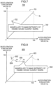
- Fig. 5 shows a two-dimensional graph having a horizontal axis denoting the acceleration evaluation value Ea and a vertical axis denoting the deceleration evaluation value Ed.
- the manipulation type determination part 65 determines the manipulation type of the operator as the "aggressive" type when the acceleration evaluation value Ea and the deceleration evaluation value Ed are plotted in an area AR1 (e.g., the black circular point BS in Fig. 5 ) to the lower right of the straight line SL in the two-dimensional graph in Fig. 5 . Specifically, in the embodiment, the manipulation type determination part 65 determines the manipulation type of the operator as the "aggressive" type when the acceleration evaluation value Ea is larger than the deceleration evaluation value Ed (Ea > Ed).
- the manipulation type determination part 65 determines the manipulation type of the operator as the "cautious" type when the acceleration evaluation value Ea and the deceleration evaluation value Ed are plotted on the straight line SL or in an area AR2 to the upper left of the straight line SL (e.g., the black trianglar point BT in Fig. 5 ) in the two-dimensional graph in Fig. 5 .
- the manipulation type determination part 65 determines the manipulation type of the operator as the "cautious" type when the acceleration evaluation value Ea is equal to or smaller than the deceleration evaluation value Ed (Ea ⁇ Ed).
- step S7 the display control part 66 generates a manipulation support image including support information associated with the manipulation type and outputs the generated manipulation support image to the monitor 83.
- the display control part 66 acquires the support information associated with the manipulation type determined in step S6 with reference to a support information table 72 shown in Fig. 6 . For instance, when the manipulation type is determined as the "cautious" type in step S6, the display control part 66 acquires support information (in the bold framed box) associated with the "cautious" type of the "boom raising and suspending".
- the support information recorded in the support information table 72 represents information (message) for presenting a state (intensity of the engine sound, soil in the bucket or the like) of the hydraulic excavator 1 to be focused on by the operator.
- the support information is information (message) for indirectly improving a skill for the boom raising and suspending manipulation by showing the state of the hydraulic excavator 1 to be focused on by the operator.
- the support information table 72 stores a manipulation type and support information associated with the manipulation type for each specific manipulation.
- the specific manipulation include the boom raising and suspending manipulation and a slewing position determining manipulation.
- the manipulation type includes the above-described "cautious” type and "aggressive type". For instance, when the specific manipulation indicates the “boom raising and suspending manipulation” and the manipulation type indicates the "cautious” type, adoptable support information shows a message, "Manipulate to make intensity of engine sound clearly heard.”, to encourage a more aggressive manipulation.
- adoptable support information shows a message, "Manipulate to avoid spilling soil from bucket.”, to encourage a more cautious manipulation.
- the support information includes information for presenting a state (e.g., "intensity of the engine sound") of the hydraulic excavator 1 to be focused on by the operator and information (e.g., "Manipulate to make intensity of engine sound clearly heard.") to directly improve a skill for a specific manipulation. Accordingly, the operator can grasp a way of operating the hydraulic excavator 1 to be in a certain state for improvement in the specific manipulation.
- the display control part 66 generates a manipulation support image 700 including support information (speech bubble image portion in Fig. 7 ) superimposed on the two-dimensional graph 701, in which the acceleration evaluation value Ea and the deceleration evaluation value Ed are plotted, to be displayed, and outputs the generated manipulation support image to the monitor 83.
- Fig. 7 shows an example of the manipulation support image 700 about the specific manipulation indicating the "boom raising and suspending manipulation” and the manipulation type indicating the "cautious” type.
- the manipulation support image 700 includes the speech bubble image 702 showing support information, and an image having a two-dimensional graph 701 in which a point 703 indicating the acceleration evaluation value Ea and the deceleration evaluation value Ed of the operator is plotted.
- a straight line SL distinguishing the "cautious" type and the "aggressive" type concerning the manipulation type from each other is plotted.
- the speech bubble image 702 is displayed in association with the point 703.
- the speech bubble image 702 shows support information (here, "Manipulate to make intensity of engine sound clearly heard.") registered in the support information table 72 in advance for the specific manipulation (boom raising and suspending manipulation) and the manipulation type that is the "cautious" type.
- the operator having browsed the manipulation support image 700 can grasp a manipulation tendency thereof and a matter to be improved in the manipulation.
- the manipulation type of the operator is determined on the basis of the acceleration evaluation value Ea and the deceleration evaluation value Ed, and the support information associated with the determined manipulation type is notified to the operator.
- the state (intensity of the engine sound or soil in the bucket) of the hydraulic excavator 1 as support information to be focused on by the operator is presented.
- effective manipulation support is available to an unskilled operator facing difficulty in following a direct instruction.
- the boom raising and suspending manipulation is described as an example of the specific manipulation in the embodiment, the specific manipulation is not limited thereto.
- the concept of the present invention is adoptable for any manipulation accompanied by acceleration and deceleration. Specifically, a manipulation type of an operator for a slewing position determining manipulation of executing slewing and suspension in a predetermined direction is determined, and support information associated with the manipulation type is presentable to the operator.
- each of the acceleration data and the deceleration data is specified at an acceleration rate ⁇ (t) calculated on the basis of the actual speed S a (t), but the specifying way is not limited thereto.
- Each of the acceleration data and the deceleration data may be specified by using only shift data (shift average or the like) of the actuation amount U(t).
- each of the acceleration data and the deceleration data may be specified in accordance with a combination of the acceleration rate ⁇ (t) and the actuation amount U(t).
- the manipulation support image 700 including the support information (speech bubble image 702 in Fig. 7 ) superimposed on the two-dimensional graph 701 in which the acceleration evaluation value Ea and the deceleration evaluation value Ed are plotted is displayed on the monitor 83, but the present invention is not limited thereto.
- the manipulation support image 700 showing only a text (message in the speech bubble image 702) of the support information may be output to the monitor 83 without displaying of the two-dimensional graph 701.
- the manipulation support image 700 ( Fig. 7 ) in which only a single acceleration evaluation value Ea and a single deceleration evaluation value Ed are plotted on the premise that the boom raising and suspending manipulation is executed once, but the manipulation support image is not limited thereto.
- a manipulation support image 800 ( Fig. 8 ) in which a plurality of acceleration evaluation values Ea and a plurality of deceleration evaluation values Ed are plotted may be generated.
- the manipulation support image 800 includes an image having a two-dimensional graph 801 in which a plurality of points 803 each indicating the acceleration evaluation value Ea and the deceleration evaluation value Ed, and an indicator 804 showing a time shift of each point 803 are further plotted.
- the indicator 804 connects the points 803 in a time series.
- the two-dimensional graph 801 has the same vertical axis and horizontal axis as those of the two-dimensional graph 701.
- the manipulation support image 800 includes a speech bubble image 802. Details of the speech bubble image 802 are the same as those of the speech bubble image 702.
- the evaluation value calculation part 64 may store, in a time series, the acceleration evaluation value Ea and the deceleration evaluation value Ed in the storage device 7 at each execution of the boom raising and suspending manipulation.
- the display control part 66 may generate the manipulation support image 800 including an image having the two-dimensional graph 801 in which the points 803 and the indicator 804 are plotted.
- manipulation support image 700 ( Fig. 7 ) including the support information is output to the monitor 83 at the time of completion of the boom raising and suspending manipulation, the output way is not limited thereto.
- the controller 6 may determine a frequency of outputting the manipulation support image 700 on the basis of a distance L (see Fig. 9 ) between a point 903 (which is an example of evaluation data) indicating a previous acceleration evaluation value Ea and a previous deceleration evaluation value Ed, and a target point TV (which is an example of target data), and output the manipulation support image 700 to the monitor 83 at the determined frequency.
- the target point TV is defined by an acceleration target value predetermined for the acceleration evaluation value and a deceleration target value predetermined for the deceleration evaluation value. An example of each of the acceleration target value and the deceleration target value indicates "100".
- the controller 10 may further include a frequency determination part 67 to determine the frequency of outputting the manipulation support image 700.
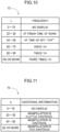
- the frequency determination part 67 determines a frequency associated with a value of the calculated distance L as an output frequency of the manipulation support image 700 with reference to a frequency table 73 in Fig. 10 .
- the numeral "100" in the first parentheses indicates the acceleration target value and the numeral "100" in the second parentheses indicates the deceleration target value.
- the frequency table 73 defines a relation between the distance L and the frequency so that the frequency increases in accordance with an increase in the distance L.
- the frequency table 73 defines the relation between the distance and the frequency so that: the manipulation support image 700 is not displayed when a value of the distance L is equal to or larger than 0 and equal to or smaller than 19; the manipulation support image 700 is displayed at a finish of a work when the value of the distance L is equal to or larger than 20 and equal to or smaller than 39; and the manipulation support image 700 is displayed when a key of the hydraulic excavator 1 is turned off and the value of the distance L is equal to or larger than 40 and equal to or smaller than 59.
- the frequency determination part 67 determines the frequency to "once/one hour, i.e., 1h" with reference to the frequency table 73 when the value of the distance L is "62". In this case, the display control part 66 may output the manipulation support image 700 to the monitor 83 at the frequency of once an hour. The frequency determination part 67 may determine the frequency to "twice/1h" when the value of the distance L is "86". In this case, the display control part 66 may output the manipulation support image 700 at the frequency of twice an hour.
- the manipulation support image 700 when the distance between the point 903 indicating the acceleration evaluation value Ea and the deceleration evaluation value Ed, and the target point TV is longer (in other words, the skill of the operator is lower), the manipulation support image 700 is output at a high frequency. This makes it possible to encourage the operator to improve the skill thereof. Contrarily, when the distance between the point 903 indicating the acceleration evaluation value Ea and the deceleration evaluation value Ed, and the target point TV is shorter (in other words, the skill of the operator is higher), the manipulation support image 700 is output at a low frequency (or no manipulation support image is output). This makes it possible to prevent unnecessary information from being presented to the operator. Consequently, support appropriate for the skill is achievable.
- each of the manipulation support images 700, 800 including the support information associated with a manipulation type in advance is generated in the embodiment, the manipulation support image is not limited thereto.
- additional information to be added to the support information may be determined on the basis of a distance between evaluation data including an acceleration evaluation value Ea and the deceleration evaluation value Ed, and a target data set in advance, and a manipulation support image including the support information and the additional information may be generated.
- a distance "e" (see Fig. 9 ) of a perpendicular line extending downward from the point 903 (which is an example of the evaluation data) indicating the acceleration evaluation value Ea and the deceleration evaluation value Ed perpendicularly to the straight line SL.
- data including an acceleration evaluation value Ea and a deceleration evaluation value Eb at an intersection 904 between the perpendicular line and the straight line SL is an example of target data.
- the controller 10 may further include an additional information determination part 68 that determines additional information to be added to the support information.
- the additional information determination part 68 determines additional information associated with a value of the calculated distance "e” with reference to an additional information table 74 shown in Fig. 11 .
- the additional information table 74 represents an additional information table 74 for a specific manipulation that is the "boom raising and suspending manipulation” and a manipulation type that is the "cautious" type.
- the additional information table 74 defines the additional information based on the distance "e” so that cautiousness about manipulation is further emphasized in accordance with an increase in the distance "e”. For instance, when a value of the distance "e” is equal to or larger than 0 and equal to or smaller than 19, no additional information is displayed.
- the additional information shows, "The manipulation is a little cautious.”, when the value of the distance “e” is equal to or larger than 20 and equal to or smaller than 39.
- the additional information shows, "The manipulation is cautious.”, when the value of the distance “e” is equal to or larger than 40 and equal to or smaller than 59.
- the additional information determination part 68 determines the additional information showing, "Manipulation is too cautious.”, when the value of the distance “e” is "74".
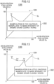
- the display control part 66 may output a manipulation support image 1200 shown in Fig. 12 to the monitor 83.
- the manipulation support image 1200 shown in Fig. 12 includes a two-dimensional graph 1201 and a speech bubble image 1202.
- the speech bubble image 1202 includes a message set containing the message, "Manipulation is too cautious.”, indicated by the additional information in addition to and prior to the message of the support information (in the bold framed box in Fig. 6 ) about the "cautious" type.
- the contents of the two-dimensional graph 1201 are the same as those of the two-dimensional graph 701.
- the additional information determination part 68 determines the additional information showing, "Manipulation is a little cautious.”, with reference to the additional information table 74 when the value of the distance "e" is "22".
- the display control part 66 may output a manipulation support image 1300 shown in Fig. 13 to the monitor 83.
- the manipulation support image 1300 shown in Fig. 13 includes a two-dimensional graph 1301 and a speech bubble image 1302.
- the speech bubble image 1302 includes a message set containing the message, "Manipulation is a little cautious.”, indicated by the additional information determined by the additional information determination part 68 in addition to and prior to the message of the support information (in the bold framed box in Fig. 6 ) about the "cautious" type.
- the two-dimensional graph 1301 is the same as the two-dimensional graph 801.
- the speech bubble image 1302 is displayed in association with a latest point indicating an acceleration evaluation value Ea and a deceleration evaluation value Eb.
- contents to be displayed on a manipulation support image is changeable on the basis of a distance (in other words, the skill of the operator) between an acceleration evaluation value Ea and a deceleration evaluation value Ed, and a target value.
- a distance in other words, the skill of the operator
- an emphatic message is added to support information and displayed for an operator having a low skill and showing a long distance between the acceleration evaluation value Ea and the deceleration evaluation value Ed, and the target data.
- an unemphatic message is added to support information and displayed or no message is displayed for an operator having a high skill and showing a short distance between the acceleration evaluation value Ea and the deceleration evaluation value Ed, and the target data.
- the additional information determination part 68 may determine the additional information on the basis of the distance L in place of the distance "e". In this case, the additional information determination part 68 may determine such emphatic additional information from the additional information table 74 in accordance with an increase in the distance L.
- the support information is visually notified through the manipulation support image in the embodiment, the notification way is not limited thereto.
- the support information may be auditorily notified with a voice or sound.
- the hydraulic excavator 1 may further include a speaker (not shown) arranged in the operator compartment.
- the controller 10 may further include a voice control part.
- the voice control part may output voice data of the support information to the speaker.
- the voice control part serves as an example of the "notification part".
- the support information represents a message for indirectly improving the skill for the boom raising and suspending manipulation on the basis of a state (intensity of the engine sound) of the hydraulic excavator 1 to be focused on by the operator in the embodiment
- the support information is not limited thereto.
- the support information may represent a message specifically instructing a content (e.g., manipulation way of a lever) of the boom raising and suspending manipulation.
- the support information represents a message for directly improving the skill for the boom raising and suspending manipulation.
- manipulation support image 700 shown in Fig. 7 is displayed in real time (in the work) in the embodiment, the displaying is not limited thereto.
- a manipulation support image may represent a report obtained after the work and including: a skill shift (growth rate) achieved owing to the support (manipulation support); or information to be focused on to realize a better manipulation.
- manipulation type of the operator includes the "aggressive” type and the "cautious” type in the embodiment, the manipulation type is not limited thereto.
- the manipulation type may further include an "intermediate” type between the "aggressive” type and the "cautious” type.
- the manipulation type determination part 65 may determine the manipulation type as the "aggressive" type when an acceleration evaluation value Ea is larger than a deceleration evaluation value Eb and a difference
- a construction machine includes: an operation data acquisition part that acquires operation data about a specific manipulation by an operator to a manipulation target included in the construction machine; an acceleration and deceleration data specifying part that specifies acceleration data being operation data in an acceleration period of the manipulation target and deceleration data being operation data in a deceleration period of the manipulation target among the operation data; an evaluation data acquisition part that acquires acceleration evaluation data for evaluating the acceleration data, and deceleration evaluation data for evaluating the deceleration data; an evaluation value calculation part that calculates, on the basis of the acceleration data and the acceleration evaluation data, an acceleration evaluation value indicating a skill of the operator in the acceleration period, and calculates, on the basis of the deceleration data and the deceleration evaluation data, a deceleration evaluation value indicating a skill of the operator in the deceleration period; a manipulation type determination part that determines, on the basis of the acceleration evaluation value and the deceleration evaluation value, a manipulation type of the operator; and a notification part that gives notification of support information
- the manipulation type of the operator is determined on the basis of the acceleration evaluation value and the deceleration evaluation value, and the support information associated with the manipulation type is notified to the operator. Hence, a specific manipulation by the operator is more appropriately supported in association with the manipulation type of the operator.
- the support information preferably shows a state of the construction machine to be focused on by the operator to improve a skill for the specific manipulation.
- the support information showing the state of the construction machine to be focused on by the operator to improve the skill of the operator is presentable to the operator.
- the notification part preferably generates a manipulation support image including the support information and an image having a two-dimensional graph in which the acceleration evaluation value and the deceleration evaluation value are plotted over a coordinate axis of the acceleration evaluation value and a coordinate axis of the deceleration evaluation value, and the notification part preferably outputs the generated manipulation support image to a display part.
- the manipulation support image including the support information and the image having the two-dimensional graph in which the acceleration evaluation value and the deceleration evaluation value are plotted is displayed, and thus, the operator can easily confirm the manipulation type thereof.
- the construction machine preferably further includes a storage part that stores, in a time series, the acceleration evaluation value and the deceleration evaluation value calculated by the evaluation value calculation part at each execution of the specific manipulation.
- the notification part preferably generates the manipulation support image including an image having the two-dimensional graph in which a plurality of points each indicating the acceleration evaluation value and the deceleration evaluation value stored in the time series, and an indicator showing a time shift of the acceleration evaluation value and the deceleration evaluation value are further plotted.
- the operator can easily grasp the time shift of the acceleration evaluation value and the deceleration evaluation value through the two-dimensional graph.
- the construction machine preferably further includes a frequency determination part that determines a frequency of the notification of the support information on the basis of a distance between evaluation data including the acceleration evaluation value and the deceleration evaluation value, and target data set in advance.
- the notification part preferably gives the notification of the support information at the frequency determined by the frequency determination part.
- This configuration enables notification of the support information at the frequency based on the distance between the evaluation data and the target data.
- the construction machine preferably further includes an additional information determination part that determines additional information to be added to the support information on the basis of the distance between the evaluation data including the acceleration evaluation value and the deceleration evaluation value, and the target data set in advance.
- the notification part preferably gives the notification of the support information including the additional information determined by the additional information determination part.
- This configuration allows the support information to include the additional information determined on the basis of the distance between the evaluation data and the target data.
- the manipulation type determination part preferably determines the manipulation type of the operator as an aggressive type when the acceleration evaluation value is larger than the deceleration evaluation value.
- This configuration achieves determination on the manipulation type of the operator in detail.
- the manipulation type determination part preferably determines the manipulation type of the operator as the aggressive type when the acceleration evaluation value is larger than the deceleration evaluation value by a predetermined value or larger, determines the manipulation type of the operator as a cautious type when the deceleration evaluation value is larger than the acceleration evaluation value by the predetermined value or larger, and determines the manipulation type of the operator as an intermediate type when an absolute value of a difference between the acceleration evaluation value and the deceleration evaluation value is smaller than the predetermined value.
- This configuration achieves determination on the manipulation type of the operator in detail.
- the manipulation type determination part preferably determines the manipulation type of the operator as the cautious type when the acceleration evaluation value is equal to or smaller than the deceleration evaluation value.
- This configuration achieves determination on the manipulation type of the operator in detail.
- the state of the construction machine preferably includes an engine sound or soil in a bucket.
- the support information is attainable by using the state of the engine sound or the soil in the bucket.
- the frequency determination part preferably determines the frequency of the notification of the support information with reference to a frequency table defining a relation between the distance and the frequency so that the frequency decreases in accordance with the increase in the distance.
- This configuration succeeds in facilitated determination on the frequency of outputting the support information.
- the evaluation value calculation part preferably decreases the acceleration evaluation value in accordance with an increase in a difference between the acceleration data and the acceleration evaluation data, and decreases the acceleration evaluation value in accordance with an increase in a difference between the deceleration data and the deceleration evaluation data.
- the acceleration evaluation value is decreased in accordance with the increase in the difference between the acceleration data and the acceleration evaluation data
- the deceleration evaluation value is decreased in accordance with the increase in the difference between the deceleration data and the deceleration evaluation data, and therefore, the acceleration evaluation value and the deceleration evaluation value are appropriately calculatable.
- the construction machine preferably further includes a manipulation part that allows the operator to execute manipulation to the manipulation target.
- the acceleration data preferably includes an acceleration actuation amount indicating an amount of actuation of the manipulation part by the operator in the acceleration period and an acceleration period value indicating a length of the acceleration period of the operator.
- the acceleration evaluation data preferably includes an acceleration actuation amount of the manipulation part by a skilled operator in an acceleration period and an acceleration period value of the skilled operator.
- the evaluation value calculation part preferably decreases the acceleration evaluation value in accordance with an increase in a difference between the acceleration actuation amount by the operator and the acceleration actuation amount by the skilled operator, and an increase in a difference between the acceleration period value of the operator and the acceleration period value of the skilled operator.
- the acceleration evaluation value is decreased in accordance with the increase in the difference between the acceleration actuation amount by the operator and the acceleration actuation amount by the skilled operator, and the increase in the difference between the acceleration period value of the operator and the acceleration period value of the skilled operator. Therefore, an appropriate acceleration evaluation value is calculatable in consideration of the acceleration actuation amount and the acceleration period value.
- the deceleration data preferably includes a deceleration actuation amount indicating an amount of actuation of the manipulation part by the operator in the deceleration period, and a suspended position of the manipulation target in the deceleration period.
- the deceleration evaluation data preferably includes a deceleration actuation amount of the manipulation part by the skilled operator in a deceleration period, and a suspended position of the manipulation target that is attained by the skilled operator.
- the evaluation value calculation part preferably decreases the deceleration evaluation value in accordance with an increase in a difference between the deceleration actuation amount by the operator and the deceleration actuation amount by the skilled operator, and an increase in a difference between the suspended position attained by the operator and the suspended position attained by the skilled operator.
- the deceleration evaluation value is decreased in accordance with the increase in the difference between the deceleration actuation amount by the operator and the deceleration actuation amount by the skilled operator, and the increase in the difference between the deceleration period value of the operator and the deceleration period value of the skilled operator. Therefore, an appropriate deceleration evaluation value is calculatable in consideration of the deceleration actuation amount and the deceleration period value.
- a construction machine includes: a storage part that stores acceleration evaluation data and deceleration evaluation data; and a controller configured to: acquire operation data about a specific manipulation: specify acceleration data being operation data in an acceleration period of a manipulation target and deceleration data being operation data in a deceleration period among operation data; acquire the acceleration evaluation data and the deceleration evaluation data from the storage part; calculate, on the basis of the acceleration data and the acceleration evaluation data, an acceleration evaluation value indicating a skill of the operator in the acceleration period, and calculate, on the basis of the deceleration data and the deceleration evaluation data, a deceleration evaluation value indicating a skill of the operator in the deceleration period; determine, on the basis of the acceleration evaluation value and the deceleration evaluation value, a manipulation type of the operator; and give notification of support information associated with the manipulation type.
- the manipulation type of the operator is determined on the basis of the acceleration evaluation value and the deceleration evaluation value, and the support information associated with the manipulation type is notified to the operator. Hence, a specific manipulation by the operator is more appropriately supported in association with the manipulation type of the operator.
- a construction machine according to the present invention is suitable for supporting a specific manipulation by an operator.
Landscapes
- Engineering & Computer Science (AREA)
- Mining & Mineral Resources (AREA)
- Civil Engineering (AREA)
- General Engineering & Computer Science (AREA)
- Structural Engineering (AREA)
- Mechanical Engineering (AREA)
- Component Parts Of Construction Machinery (AREA)
- Operation Control Of Excavators (AREA)
Applications Claiming Priority (2)
| Application Number | Priority Date | Filing Date | Title |
|---|---|---|---|
| JP2020129211A JP7457595B2 (ja) | 2020-07-30 | 2020-07-30 | 建設機械 |
| PCT/JP2021/027795 WO2022025079A1 (fr) | 2020-07-30 | 2021-07-27 | Engin de chantier |
Publications (3)
| Publication Number | Publication Date |
|---|---|
| EP4170101A1 true EP4170101A1 (fr) | 2023-04-26 |
| EP4170101A4 EP4170101A4 (fr) | 2023-12-20 |
| EP4170101B1 EP4170101B1 (fr) | 2024-12-04 |
Family
ID=80036595
Family Applications (1)
| Application Number | Title | Priority Date | Filing Date |
|---|---|---|---|
| EP21848677.7A Active EP4170101B1 (fr) | 2020-07-30 | 2021-07-27 | Engin de chantier |
Country Status (5)
| Country | Link |
|---|---|
| US (1) | US20230257966A1 (fr) |
| EP (1) | EP4170101B1 (fr) |
| JP (1) | JP7457595B2 (fr) |
| CN (1) | CN115803498B (fr) |
| WO (1) | WO2022025079A1 (fr) |
Families Citing this family (1)
| Publication number | Priority date | Publication date | Assignee | Title |
|---|---|---|---|---|
| JP2024108657A (ja) | 2023-01-31 | 2024-08-13 | 国立大学法人広島大学 | 作業機械の制御装置 |
Family Cites Families (24)
| Publication number | Priority date | Publication date | Assignee | Title |
|---|---|---|---|---|
| JP3499681B2 (ja) * | 1996-07-05 | 2004-02-23 | 株式会社神戸製鋼所 | 油圧ショベルの作業種別判別装置 |
| US6085583A (en) * | 1999-05-24 | 2000-07-11 | Carnegie Mellon University | System and method for estimating volume of material swept into the bucket of a digging machine |
| JP4475767B2 (ja) * | 2000-08-03 | 2010-06-09 | 株式会社小松製作所 | 作業用車両 |
| US7769499B2 (en) * | 2006-04-05 | 2010-08-03 | Zonar Systems Inc. | Generating a numerical ranking of driver performance based on a plurality of metrics |
| JP5133755B2 (ja) * | 2008-03-28 | 2013-01-30 | 株式会社小松製作所 | 建設機械の運転評価システム及び運転評価方法 |
| JP5386543B2 (ja) * | 2011-05-25 | 2014-01-15 | 株式会社審調社 | 運転評価システム、運転評価用プログラム、及び運転評価方法 |
| US20150258996A1 (en) * | 2012-09-17 | 2015-09-17 | Volvo Lastvagnar Ab | Method for providing a context based coaching message to a driver of a vehicle |
| US20150004572A1 (en) * | 2013-06-26 | 2015-01-01 | Caterpillar Inc. | Real-Time Operation-Based Onboard Coaching System |
| JP2015184968A (ja) * | 2014-03-25 | 2015-10-22 | 株式会社日立製作所 | 運転特性診断方法 |
| US20150348178A1 (en) * | 2014-05-30 | 2015-12-03 | Verizon Patent And Licensing Inc. | Method and System for Renting and Sub-Renting Vehicles |
| JP6320185B2 (ja) * | 2014-06-16 | 2018-05-09 | 住友重機械工業株式会社 | ショベル支援装置 |
| US9798323B2 (en) * | 2014-07-28 | 2017-10-24 | GM Global Technology Operations LLC | Crowd-sourced transfer-of-control policy for automated vehicles |
| JP6502148B2 (ja) * | 2015-04-03 | 2019-04-17 | 株式会社日立製作所 | 運転診断方法および運転診断装置 |
| JP6407132B2 (ja) * | 2015-11-30 | 2018-10-17 | 日立建機株式会社 | 作業機械の操作支援装置 |
| KR20180135647A (ko) * | 2017-06-13 | 2018-12-21 | 현대건설기계 주식회사 | 건설기계의 작업종류 인식시스템 및 이를 이용한 건설기계 제어방법 |
| US10817750B2 (en) * | 2018-04-09 | 2020-10-27 | Diveplane Corporation | Data inclusion in computer-based reasoning models |
| JP7072461B2 (ja) * | 2018-07-30 | 2022-05-20 | 本田技研工業株式会社 | 運転評価システム、運転評価方法、プログラム、及び媒体 |
| JP7175666B2 (ja) * | 2018-07-31 | 2022-11-21 | 株式会社小松製作所 | 指標値特定装置および指標値特定方法 |
| US20200048866A1 (en) * | 2018-08-09 | 2020-02-13 | Caterpillar Inc. | System and computerized method for adjusting machine capabilities in response to machine operating conditions |
| JP7097022B2 (ja) * | 2018-08-31 | 2022-07-07 | コベルコ建機株式会社 | 建設機械 |
| US11225163B2 (en) * | 2019-04-12 | 2022-01-18 | GM Global Technology Operations LLC | Electric vehicle charging platform |
| US11341440B2 (en) * | 2019-12-11 | 2022-05-24 | Caterpillar Inc. | Work order integration system |
| JP7363621B2 (ja) * | 2020-03-17 | 2023-10-18 | トヨタ自動車株式会社 | 情報処理装置、情報処理方法、及び、プログラム |
| CN115427639A (zh) * | 2020-05-25 | 2022-12-02 | 住友建机株式会社 | 挖土机及挖土机用的系统 |
-
2020
- 2020-07-30 JP JP2020129211A patent/JP7457595B2/ja active Active
-
2021
- 2021-07-27 EP EP21848677.7A patent/EP4170101B1/fr active Active
- 2021-07-27 CN CN202180049632.5A patent/CN115803498B/zh active Active
- 2021-07-27 US US18/006,220 patent/US20230257966A1/en active Pending
- 2021-07-27 WO PCT/JP2021/027795 patent/WO2022025079A1/fr not_active Ceased
Also Published As
| Publication number | Publication date |
|---|---|
| EP4170101B1 (fr) | 2024-12-04 |
| JP2022025976A (ja) | 2022-02-10 |
| CN115803498A (zh) | 2023-03-14 |
| US20230257966A1 (en) | 2023-08-17 |
| CN115803498B (zh) | 2026-01-27 |
| EP4170101A4 (fr) | 2023-12-20 |
| JP7457595B2 (ja) | 2024-03-28 |
| WO2022025079A1 (fr) | 2022-02-03 |
Similar Documents
| Publication | Publication Date | Title |
|---|---|---|
| US11021851B2 (en) | System and method for vibration monitoring of a mining machine | |
| US6532409B1 (en) | Target excavation surface setting device for excavation machine, recording medium therefor and display unit | |
| CN110300827B (zh) | 工程机械 | |
| CN108350680B (zh) | 作业机械的操作辅助装置 | |
| WO2002040783A1 (fr) | Dispositif d'affichage et controleur d'affichage pour materiel de construction | |
| EP4170101B1 (fr) | Engin de chantier | |
| KR20060118415A (ko) | 건설 기계의 운전 시스템 | |
| CN109689978A (zh) | 作业机械 | |
| JP7003107B2 (ja) | ショベル | |
| EP4050164B1 (fr) | Serveur d'aide au travail et procédé pour sélectionner un dispositif d'imagerie | |
| CN113366172B (zh) | 用于呈现描述拆除机器人的运行操作状况的信息的方法、设备和用户界面 | |
| JP2000129727A (ja) | 建設機械の作業量計測装置 | |
| JP7183744B2 (ja) | 建設機械の遠隔操作装置 | |
| KR102378805B1 (ko) | 건설 기계 | |
| JP6425618B2 (ja) | 作業機械の操作支援装置 | |
| JP2002081096A (ja) | 建設機械の表示装置及び表示制御装置 | |
| EP4567204A1 (fr) | Machine de travail | |
| JP7567545B2 (ja) | 作業機械 | |
| JP2021080657A (ja) | 操作対象装置及び建設機械 | |
| JPH0748838A (ja) | 連続壁掘削機姿勢のグラフィック表示方法 | |
| JP2016098624A (ja) | 作業機械の操作支援システム | |
| JP2002180504A (ja) | 建設機械の信号処理装置及びモニタ表示装置 | |
| JP2003337143A (ja) | 波形測定装置 | |
| WO2024034660A1 (fr) | Système d'aide au travail | |
| JP2024140560A (ja) | 遠隔操作装置 |
Legal Events
| Date | Code | Title | Description |
|---|---|---|---|
| STAA | Information on the status of an ep patent application or granted ep patent |
Free format text: STATUS: THE INTERNATIONAL PUBLICATION HAS BEEN MADE |
|
| PUAI | Public reference made under article 153(3) epc to a published international application that has entered the european phase |
Free format text: ORIGINAL CODE: 0009012 |
|
| STAA | Information on the status of an ep patent application or granted ep patent |
Free format text: STATUS: REQUEST FOR EXAMINATION WAS MADE |
|
| 17P | Request for examination filed |
Effective date: 20230117 |
|
| AK | Designated contracting states |
Kind code of ref document: A1 Designated state(s): AL AT BE BG CH CY CZ DE DK EE ES FI FR GB GR HR HU IE IS IT LI LT LU LV MC MK MT NL NO PL PT RO RS SE SI SK SM TR |
|
| DAV | Request for validation of the european patent (deleted) | ||
| DAX | Request for extension of the european patent (deleted) | ||
| A4 | Supplementary search report drawn up and despatched |
Effective date: 20231117 |
|
| RIC1 | Information provided on ipc code assigned before grant |
Ipc: E02F 9/26 20060101AFI20231113BHEP |
|
| GRAP | Despatch of communication of intention to grant a patent |
Free format text: ORIGINAL CODE: EPIDOSNIGR1 |
|
| STAA | Information on the status of an ep patent application or granted ep patent |
Free format text: STATUS: GRANT OF PATENT IS INTENDED |
|
| INTG | Intention to grant announced |
Effective date: 20240712 |
|
| GRAS | Grant fee paid |
Free format text: ORIGINAL CODE: EPIDOSNIGR3 |
|
| GRAA | (expected) grant |
Free format text: ORIGINAL CODE: 0009210 |
|
| STAA | Information on the status of an ep patent application or granted ep patent |
Free format text: STATUS: THE PATENT HAS BEEN GRANTED |
|
| AK | Designated contracting states |
Kind code of ref document: B1 Designated state(s): AL AT BE BG CH CY CZ DE DK EE ES FI FR GB GR HR HU IE IS IT LI LT LU LV MC MK MT NL NO PL PT RO RS SE SI SK SM TR |
|
| REG | Reference to a national code |
Ref country code: CH Ref legal event code: EP |
|
| REG | Reference to a national code |
Ref country code: DE Ref legal event code: R096 Ref document number: 602021023051 Country of ref document: DE |
|
| REG | Reference to a national code |
Ref country code: IE Ref legal event code: FG4D |
|
| REG | Reference to a national code |
Ref country code: LT Ref legal event code: MG9D |
|
| REG | Reference to a national code |
Ref country code: NL Ref legal event code: MP Effective date: 20241204 |
|
| PG25 | Lapsed in a contracting state [announced via postgrant information from national office to epo] |
Ref country code: HR Free format text: LAPSE BECAUSE OF FAILURE TO SUBMIT A TRANSLATION OF THE DESCRIPTION OR TO PAY THE FEE WITHIN THE PRESCRIBED TIME-LIMIT Effective date: 20241204 |
|
| PG25 | Lapsed in a contracting state [announced via postgrant information from national office to epo] |
Ref country code: FI Free format text: LAPSE BECAUSE OF FAILURE TO SUBMIT A TRANSLATION OF THE DESCRIPTION OR TO PAY THE FEE WITHIN THE PRESCRIBED TIME-LIMIT Effective date: 20241204 |
|
| PG25 | Lapsed in a contracting state [announced via postgrant information from national office to epo] |
Ref country code: BG Free format text: LAPSE BECAUSE OF FAILURE TO SUBMIT A TRANSLATION OF THE DESCRIPTION OR TO PAY THE FEE WITHIN THE PRESCRIBED TIME-LIMIT Effective date: 20241204 |
|
| PG25 | Lapsed in a contracting state [announced via postgrant information from national office to epo] |
Ref country code: ES Free format text: LAPSE BECAUSE OF FAILURE TO SUBMIT A TRANSLATION OF THE DESCRIPTION OR TO PAY THE FEE WITHIN THE PRESCRIBED TIME-LIMIT Effective date: 20241204 |
|
| PG25 | Lapsed in a contracting state [announced via postgrant information from national office to epo] |
Ref country code: NO Free format text: LAPSE BECAUSE OF FAILURE TO SUBMIT A TRANSLATION OF THE DESCRIPTION OR TO PAY THE FEE WITHIN THE PRESCRIBED TIME-LIMIT Effective date: 20250304 |
|
| PG25 | Lapsed in a contracting state [announced via postgrant information from national office to epo] |
Ref country code: LV Free format text: LAPSE BECAUSE OF FAILURE TO SUBMIT A TRANSLATION OF THE DESCRIPTION OR TO PAY THE FEE WITHIN THE PRESCRIBED TIME-LIMIT Effective date: 20241204 Ref country code: GR Free format text: LAPSE BECAUSE OF FAILURE TO SUBMIT A TRANSLATION OF THE DESCRIPTION OR TO PAY THE FEE WITHIN THE PRESCRIBED TIME-LIMIT Effective date: 20250305 |
|
| PG25 | Lapsed in a contracting state [announced via postgrant information from national office to epo] |
Ref country code: RS Free format text: LAPSE BECAUSE OF FAILURE TO SUBMIT A TRANSLATION OF THE DESCRIPTION OR TO PAY THE FEE WITHIN THE PRESCRIBED TIME-LIMIT Effective date: 20250304 |
|
| PG25 | Lapsed in a contracting state [announced via postgrant information from national office to epo] |
Ref country code: NL Free format text: LAPSE BECAUSE OF FAILURE TO SUBMIT A TRANSLATION OF THE DESCRIPTION OR TO PAY THE FEE WITHIN THE PRESCRIBED TIME-LIMIT Effective date: 20241204 |
|
| REG | Reference to a national code |
Ref country code: AT Ref legal event code: MK05 Ref document number: 1748294 Country of ref document: AT Kind code of ref document: T Effective date: 20241204 |
|
| PG25 | Lapsed in a contracting state [announced via postgrant information from national office to epo] |
Ref country code: SM Free format text: LAPSE BECAUSE OF FAILURE TO SUBMIT A TRANSLATION OF THE DESCRIPTION OR TO PAY THE FEE WITHIN THE PRESCRIBED TIME-LIMIT Effective date: 20241204 |
|
| PG25 | Lapsed in a contracting state [announced via postgrant information from national office to epo] |
Ref country code: PL Free format text: LAPSE BECAUSE OF FAILURE TO SUBMIT A TRANSLATION OF THE DESCRIPTION OR TO PAY THE FEE WITHIN THE PRESCRIBED TIME-LIMIT Effective date: 20241204 |
|
| PG25 | Lapsed in a contracting state [announced via postgrant information from national office to epo] |
Ref country code: IS Free format text: LAPSE BECAUSE OF FAILURE TO SUBMIT A TRANSLATION OF THE DESCRIPTION OR TO PAY THE FEE WITHIN THE PRESCRIBED TIME-LIMIT Effective date: 20250404 |
|
| PG25 | Lapsed in a contracting state [announced via postgrant information from national office to epo] |
Ref country code: PT Free format text: LAPSE BECAUSE OF FAILURE TO SUBMIT A TRANSLATION OF THE DESCRIPTION OR TO PAY THE FEE WITHIN THE PRESCRIBED TIME-LIMIT Effective date: 20250404 |
|
| PG25 | Lapsed in a contracting state [announced via postgrant information from national office to epo] |
Ref country code: EE Free format text: LAPSE BECAUSE OF FAILURE TO SUBMIT A TRANSLATION OF THE DESCRIPTION OR TO PAY THE FEE WITHIN THE PRESCRIBED TIME-LIMIT Effective date: 20241204 |
|
| PG25 | Lapsed in a contracting state [announced via postgrant information from national office to epo] |
Ref country code: RO Free format text: LAPSE BECAUSE OF FAILURE TO SUBMIT A TRANSLATION OF THE DESCRIPTION OR TO PAY THE FEE WITHIN THE PRESCRIBED TIME-LIMIT Effective date: 20241204 Ref country code: AT Free format text: LAPSE BECAUSE OF FAILURE TO SUBMIT A TRANSLATION OF THE DESCRIPTION OR TO PAY THE FEE WITHIN THE PRESCRIBED TIME-LIMIT Effective date: 20241204 |
|
| PG25 | Lapsed in a contracting state [announced via postgrant information from national office to epo] |
Ref country code: SK Free format text: LAPSE BECAUSE OF FAILURE TO SUBMIT A TRANSLATION OF THE DESCRIPTION OR TO PAY THE FEE WITHIN THE PRESCRIBED TIME-LIMIT Effective date: 20241204 |
|
| PG25 | Lapsed in a contracting state [announced via postgrant information from national office to epo] |
Ref country code: CZ Free format text: LAPSE BECAUSE OF FAILURE TO SUBMIT A TRANSLATION OF THE DESCRIPTION OR TO PAY THE FEE WITHIN THE PRESCRIBED TIME-LIMIT Effective date: 20241204 |
|
| PG25 | Lapsed in a contracting state [announced via postgrant information from national office to epo] |
Ref country code: IT Free format text: LAPSE BECAUSE OF FAILURE TO SUBMIT A TRANSLATION OF THE DESCRIPTION OR TO PAY THE FEE WITHIN THE PRESCRIBED TIME-LIMIT Effective date: 20241204 |
|
| REG | Reference to a national code |
Ref country code: DE Ref legal event code: R097 Ref document number: 602021023051 Country of ref document: DE |
|
| PG25 | Lapsed in a contracting state [announced via postgrant information from national office to epo] |
Ref country code: SE Free format text: LAPSE BECAUSE OF FAILURE TO SUBMIT A TRANSLATION OF THE DESCRIPTION OR TO PAY THE FEE WITHIN THE PRESCRIBED TIME-LIMIT Effective date: 20241204 |
|
| PG25 | Lapsed in a contracting state [announced via postgrant information from national office to epo] |
Ref country code: DK Free format text: LAPSE BECAUSE OF FAILURE TO SUBMIT A TRANSLATION OF THE DESCRIPTION OR TO PAY THE FEE WITHIN THE PRESCRIBED TIME-LIMIT Effective date: 20241204 |
|
| PGFP | Annual fee paid to national office [announced via postgrant information from national office to epo] |
Ref country code: DE Payment date: 20250728 Year of fee payment: 5 |
|
| PLBE | No opposition filed within time limit |
Free format text: ORIGINAL CODE: 0009261 |
|
| STAA | Information on the status of an ep patent application or granted ep patent |
Free format text: STATUS: NO OPPOSITION FILED WITHIN TIME LIMIT |
|
| REG | Reference to a national code |
Ref country code: CH Ref legal event code: L10 Free format text: ST27 STATUS EVENT CODE: U-0-0-L10-L00 (AS PROVIDED BY THE NATIONAL OFFICE) Effective date: 20251015 |
|
| PGFP | Annual fee paid to national office [announced via postgrant information from national office to epo] |
Ref country code: GB Payment date: 20250724 Year of fee payment: 5 |
|
| PGFP | Annual fee paid to national office [announced via postgrant information from national office to epo] |
Ref country code: FR Payment date: 20250723 Year of fee payment: 5 |
|
| 26N | No opposition filed |
Effective date: 20250905 |
|
| REG | Reference to a national code |
Ref country code: CH Ref legal event code: H13 Free format text: ST27 STATUS EVENT CODE: U-0-0-H10-H13 (AS PROVIDED BY THE NATIONAL OFFICE) Effective date: 20260224 |
|
| PG25 | Lapsed in a contracting state [announced via postgrant information from national office to epo] |
Ref country code: LU Free format text: LAPSE BECAUSE OF NON-PAYMENT OF DUE FEES Effective date: 20250727 |
|
| REG | Reference to a national code |
Ref country code: BE Ref legal event code: MM Effective date: 20250731 |
|
| PG25 | Lapsed in a contracting state [announced via postgrant information from national office to epo] |
Ref country code: BE Free format text: LAPSE BECAUSE OF NON-PAYMENT OF DUE FEES Effective date: 20250731 |
|
| PG25 | Lapsed in a contracting state [announced via postgrant information from national office to epo] |
Ref country code: CH Free format text: LAPSE BECAUSE OF NON-PAYMENT OF DUE FEES Effective date: 20250731 |