EP4170120B1 - Grille roulante - Google Patents
Grille roulante Download PDFInfo
- Publication number
- EP4170120B1 EP4170120B1 EP22200708.0A EP22200708A EP4170120B1 EP 4170120 B1 EP4170120 B1 EP 4170120B1 EP 22200708 A EP22200708 A EP 22200708A EP 4170120 B1 EP4170120 B1 EP 4170120B1
- Authority
- EP
- European Patent Office
- Prior art keywords
- region
- rod
- members
- fitting part
- guide
- Prior art date
- Legal status (The legal status is an assumption and is not a legal conclusion. Google has not performed a legal analysis and makes no representation as to the accuracy of the status listed.)
- Active
Links
Images


Classifications
-
- E—FIXED CONSTRUCTIONS
- E06—DOORS, WINDOWS, SHUTTERS, OR ROLLER BLINDS IN GENERAL; LADDERS
- E06B—FIXED OR MOVABLE CLOSURES FOR OPENINGS IN BUILDINGS, VEHICLES, FENCES OR LIKE ENCLOSURES IN GENERAL, e.g. DOORS, WINDOWS, BLINDS, GATES
- E06B9/00—Screening or protective devices for wall or similar openings, with or without operating or securing mechanisms; Closures of similar construction
- E06B9/56—Operating, guiding or securing devices or arrangements for roll-type closures; Spring drums; Tape drums; Counterweighting arrangements therefor
- E06B9/58—Guiding devices
-
- E—FIXED CONSTRUCTIONS
- E06—DOORS, WINDOWS, SHUTTERS, OR ROLLER BLINDS IN GENERAL; LADDERS
- E06B—FIXED OR MOVABLE CLOSURES FOR OPENINGS IN BUILDINGS, VEHICLES, FENCES OR LIKE ENCLOSURES IN GENERAL, e.g. DOORS, WINDOWS, BLINDS, GATES
- E06B9/00—Screening or protective devices for wall or similar openings, with or without operating or securing mechanisms; Closures of similar construction
- E06B9/02—Shutters, movable grilles, or other safety closing devices, e.g. against burglary
- E06B9/08—Roll-type closures
- E06B9/11—Roller shutters
- E06B9/15—Roller shutters with closing members formed of slats or the like
-
- E—FIXED CONSTRUCTIONS
- E06—DOORS, WINDOWS, SHUTTERS, OR ROLLER BLINDS IN GENERAL; LADDERS
- E06B—FIXED OR MOVABLE CLOSURES FOR OPENINGS IN BUILDINGS, VEHICLES, FENCES OR LIKE ENCLOSURES IN GENERAL, e.g. DOORS, WINDOWS, BLINDS, GATES
- E06B9/00—Screening or protective devices for wall or similar openings, with or without operating or securing mechanisms; Closures of similar construction
- E06B9/02—Shutters, movable grilles, or other safety closing devices, e.g. against burglary
- E06B9/08—Roll-type closures
- E06B9/18—Roll-type grilles
-
- B—PERFORMING OPERATIONS; TRANSPORTING
- B66—HOISTING; LIFTING; HAULING
- B66F—HOISTING, LIFTING, HAULING OR PUSHING, NOT OTHERWISE PROVIDED FOR, e.g. DEVICES WHICH APPLY A LIFTING OR PUSHING FORCE DIRECTLY TO THE SURFACE OF A LOAD
- B66F9/00—Devices for lifting or lowering bulky or heavy goods for loading or unloading purposes
- B66F9/06—Devices for lifting or lowering bulky or heavy goods for loading or unloading purposes movable, with their loads, on wheels or the like, e.g. fork-lift trucks
- B66F9/07—Floor-to-roof stacking devices, e.g. "stacker cranes", "retrievers"
-
- E—FIXED CONSTRUCTIONS
- E06—DOORS, WINDOWS, SHUTTERS, OR ROLLER BLINDS IN GENERAL; LADDERS
- E06B—FIXED OR MOVABLE CLOSURES FOR OPENINGS IN BUILDINGS, VEHICLES, FENCES OR LIKE ENCLOSURES IN GENERAL, e.g. DOORS, WINDOWS, BLINDS, GATES
- E06B9/00—Screening or protective devices for wall or similar openings, with or without operating or securing mechanisms; Closures of similar construction
- E06B9/02—Shutters, movable grilles, or other safety closing devices, e.g. against burglary
- E06B9/08—Roll-type closures
- E06B9/11—Roller shutters
-
- E—FIXED CONSTRUCTIONS
- E06—DOORS, WINDOWS, SHUTTERS, OR ROLLER BLINDS IN GENERAL; LADDERS
- E06B—FIXED OR MOVABLE CLOSURES FOR OPENINGS IN BUILDINGS, VEHICLES, FENCES OR LIKE ENCLOSURES IN GENERAL, e.g. DOORS, WINDOWS, BLINDS, GATES
- E06B9/00—Screening or protective devices for wall or similar openings, with or without operating or securing mechanisms; Closures of similar construction
- E06B9/56—Operating, guiding or securing devices or arrangements for roll-type closures; Spring drums; Tape drums; Counterweighting arrangements therefor
- E06B9/80—Safety measures against dropping or unauthorised opening; Braking or immobilising devices; Devices for limiting unrolling
-
- E—FIXED CONSTRUCTIONS
- E05—LOCKS; KEYS; WINDOW OR DOOR FITTINGS; SAFES
- E05Y—INDEXING SCHEME ASSOCIATED WITH SUBCLASSES E05D AND E05F, RELATING TO CONSTRUCTION ELEMENTS, ELECTRIC CONTROL, POWER SUPPLY, POWER SIGNAL OR TRANSMISSION, USER INTERFACES, MOUNTING OR COUPLING, DETAILS, ACCESSORIES, AUXILIARY OPERATIONS NOT OTHERWISE PROVIDED FOR, APPLICATION THEREOF
- E05Y2900/00—Application of doors, windows, wings or fittings thereof
- E05Y2900/10—Application of doors, windows, wings or fittings thereof for buildings or parts thereof
- E05Y2900/13—Type of wing
- E05Y2900/146—Shutters
-
- E—FIXED CONSTRUCTIONS
- E06—DOORS, WINDOWS, SHUTTERS, OR ROLLER BLINDS IN GENERAL; LADDERS
- E06B—FIXED OR MOVABLE CLOSURES FOR OPENINGS IN BUILDINGS, VEHICLES, FENCES OR LIKE ENCLOSURES IN GENERAL, e.g. DOORS, WINDOWS, BLINDS, GATES
- E06B9/00—Screening or protective devices for wall or similar openings, with or without operating or securing mechanisms; Closures of similar construction
- E06B9/02—Shutters, movable grilles, or other safety closing devices, e.g. against burglary
- E06B9/08—Roll-type closures
- E06B9/11—Roller shutters
- E06B9/15—Roller shutters with closing members formed of slats or the like
- E06B2009/1505—Slat details
-
- E—FIXED CONSTRUCTIONS
- E06—DOORS, WINDOWS, SHUTTERS, OR ROLLER BLINDS IN GENERAL; LADDERS
- E06B—FIXED OR MOVABLE CLOSURES FOR OPENINGS IN BUILDINGS, VEHICLES, FENCES OR LIKE ENCLOSURES IN GENERAL, e.g. DOORS, WINDOWS, BLINDS, GATES
- E06B9/00—Screening or protective devices for wall or similar openings, with or without operating or securing mechanisms; Closures of similar construction
- E06B9/02—Shutters, movable grilles, or other safety closing devices, e.g. against burglary
- E06B9/08—Roll-type closures
- E06B9/11—Roller shutters
- E06B9/15—Roller shutters with closing members formed of slats or the like
- E06B2009/1533—Slat connections
- E06B2009/155—Slats connected by separate elements
- E06B2009/1555—Flexible elements, e.g. tapes, strips, cords or chains
-
- E—FIXED CONSTRUCTIONS
- E06—DOORS, WINDOWS, SHUTTERS, OR ROLLER BLINDS IN GENERAL; LADDERS
- E06B—FIXED OR MOVABLE CLOSURES FOR OPENINGS IN BUILDINGS, VEHICLES, FENCES OR LIKE ENCLOSURES IN GENERAL, e.g. DOORS, WINDOWS, BLINDS, GATES
- E06B9/00—Screening or protective devices for wall or similar openings, with or without operating or securing mechanisms; Closures of similar construction
- E06B9/56—Operating, guiding or securing devices or arrangements for roll-type closures; Spring drums; Tape drums; Counterweighting arrangements therefor
- E06B9/68—Operating devices or mechanisms, e.g. with electric drive
- E06B2009/6809—Control
- E06B2009/6818—Control using sensors
Definitions
- the present invention relates to a shutter including a pair of guide rails spaced apart in a first direction extending in a horizontal direction, a guide path extending in an extension direction of the pair of guide rails between the pair of guide rails in the first direction, and an opening and closing body configured to move along the guide path.
- JP 2001 115 761 A discloses an example of such a shutter.
- the shutter disclosed in JP 2001 115 761 A is assembled by attaching a sheet-shaped opening and closing body (2) to a gate-shaped frame (1a) in such a manner as to extend along the frame (1a).
- a shutter such as the one disclosed in JP 2001 115 761 A is used at the entrance of a building, or used for separating, from each other, an area in which a worker performs work and an area in which a machine operates in a factory.
- a shutter used for such an application tends to be large in size.
- the size of the opening and closing body tends to be large.
- considerable constraints tend to be imposed on the assembly work, including, for example, a wide space and a large number of workers required for the assembly work.
- FR 992 503 A discloses a shutter according to the preamble of claim 1 and which comprises a pair of guide rails and a rolling grid composed of a series of equidistant cylindrical tubes alternated with strips of curved sheet metal.
- the connection between these elements is ensured by corrugated sheet metal staples arranged in staggered rows, welded in the middle to said strips of curved sheet metal and formed at their ends as shackles wrapped around two successive cylindrical tubes.
- the invention is defined by the subject-matter of claim 1.
- a technique for solving the above-described problem is as follows.
- a shutter including: a pair of guide rails spaced apart in a first direction extending in a horizontal direction; a guide path extending in an extension direction of the pair of guide rails at a position between the pair of guide rails in the first direction; and an opening and closing body configured to move along the guide path, wherein the opening and closing body includes a plurality of rod-shaped members extending in the first direction and arranged at an interval in a guide direction extending along the guide path, and a plurality of coupling members disposed in the guide direction and configured to couple the plurality of rod-shaped members, opposite end portions of each of the plurality of rod-shaped members in the first direction are respectively guided by the pair of guide rails in such a manner as to be movable in the guide direction, each of the coupling members includes a pair of fitting parts that are spaced apart in the guide direction and configured to be fitted to a coupling target pair of rod-shaped members that are adjacent to each other in the guide direction, and
- each of the fittings has a flexibility allowing it to be pressed against the corresponding rod-shaped member from a direction orthogonal to the first direction in such a manner as to be fitted thereto, by enlarging a cut-out part, where the cover part is not formed, of the fitting part, in order to insert the rod-shaped member inside the cover part.
- the opening and closing body includes a plurality of rod-shaped members and a plurality of coupling members.
- opposite end portions of each of the plurality of rod-shaped members in the first direction X are respectively attached to a pair of guide rails, thereby arranging the plurality of rod-shaped members in the guide direction.
- a pair of fitting parts of each of the corresponding coupling member are fitted to a coupling target pair of the rod-shaped members that are adjacent to each other in the guide direction, thereby coupling the pair of rod-shaped members that are adjacent to each other in the guide direction.
- the plurality of rod-shaped members can be sequentially attached to the pair of guide rails.
- the cover part covers a range of the outer circumferential surface of the rod-shaped member, the range being smaller than a circumference of the outer circumferential surface and larger than half the circumference as viewed in the first direction. Accordingly, after the rod-shaped member has been fitted to the fitting part, the coupling member is unlikely to be detached from the rod-shaped member. Therefore, the plurality of rod-shaped members can be coupled through a simple operation, thereby forming the opening and closing body. As described above, this configuration makes it possible to realize a shutter that allows an assembly operation to be performed relatively easily even when including a large opening and closing body.
- a transport facility F is a facility in which an article 9 is transported, and various types of work are performed on the article 9.
- the transport facility F includes a shutter 100, at least one article placement portion 8 that is provided in a placement region of the shutter 100 and on which the article 9 is placeable, a work area WA in which work is performed on the article 9 placed on the article placement portion 8, and a transport area TA for transporting the article 9 to the article placement portion 8.
- the article placement portion 8 is provided between the work area WA and the transport area TA as viewed in a vertical direction.
- the article placement portion 8 includes a plurality of struts 80 disposed in the vertical direction, and an article receiving portion 81 provided on an upper portion of each of the struts 80.
- four struts 80 are disposed at intervals from each other.
- the article receiving portion 81 provided on each of the struts 80 includes a receiving surface 8Fa that receives the article 9 from below, and a guide surface 8Fb standing upright from the receiving surface 8Fa.
- the guide surface 8Fb guides, to the receiving surface 8Fa, the article 9 approaching the receiving surface 8Fa from above through a transfer operation, which will be described below, performed by the transport device T.
- the guide surface 8Fb faces a side surface of an article 9 while the article 9 is placed on the receiving surface 8Fa.
- the guide surface 8Fb also has the function of horizontally positioning the article 9 placed on the article placement portion 8.
- the shutter 100 is provided in such a manner as to cover the article placement portion 8, and configured to separate the work area WA and the transport area TA from each other. More specifically, the shutter 100 is configured to separate an area in which the article placement portion 8 is provided and the work area WA from each other, and to separate the area in which the article placement portion 8 is provided and the transport area TA from each other. Accordingly, the shutter 100 is capable of separating the work area WA and the transport area TA from each other.
- a worker W or a work robot performs various types of work.
- the worker W performs work on the article 9 placed on the article placement portion 8.
- a work platform Ws is provided in the work area WA.
- the worker W can perform work while standing on the work platform Ws.
- the work platform Ws is configured to support the worker W at a position spaced upward from a floor.
- a transport device T that transports the article 9 is provided in the transport area TA.
- the transport device T is configured to transport the article 9 to the article placement portion 8.
- the transport device T is configured as a trackless or tracked automated guided vehicle.
- the transport device T is configured to travel on a floor.
- the transport device T is configured to travel on a floor disposed at a position below the upper surface of the work platform Ws to transport the article 9.
- each article 9 includes a container 91 that houses a target object, and a pallet 90 on which the container 91 is placed (see Figs. 2 and 3 ).
- the transport device T may transport a pallet 90 with a container 91 placed thereon.
- the transport device T may transport only a pallet 90 without any container 91 placed thereon.
- examples of the target object housed in the container 91 include a finished product and a workpiece.
- the container 91 may be, for example, a cardboard box, a container box, or the like. Note that a plurality of containers 91 may be placed on the pallet 90 while being stacked.
- the transport device T includes a carriage body Ta, a plurality of travel wheels Tb attached to the carriage body Ta, and a transferrer Tc that transfers the article 9 to and from the article placement portion 8.
- the transferrer Tc transfers the article 9 to and from the article placement portion 8 by raising and lowering, between an upper position and a lower position, a placement table Td on which the article 9 can be placed. While the placement table Td is disposed at the upper position, the upper surface of the placement table Td is disposed above the receiving surfaces 8Fa of the article receiving portions 81. While the placement table Td is disposed at the lower position, the upper surface of the placement table Td is disposed below the receiving surfaces 8Fa of the article receiving portions 81.
- the transferrer Tc receives an article 9 from the article receiving portions 81 by raising the placement table Td to the upper position from the lower position while the article 9 is placed on the article receiving portions 81 of the article placement portion 8.
- the transferrer Tc delivers an article 9 to the article receiving portions 81 by lowering the placement table Td to the lower position from the upper position while the article 9 is placed on the placement table Td.
- the shutter 100 includes a pair of guide rails 1 spaced apart in a first direction X extending in the horizontal direction, a guide path R extending in an extension direction of the pair of guide rails 1 at a position between the pair of guide rails 1 in the first direction X, and an opening and closing body 2 configured to move along the guide path R.
- a first direction-first side X1 is one side in the first direction X
- a first direction-second side X2 is the other side in the first direction X
- a second direction Y is a direction orthogonal to the first direction X as viewed in the vertical direction
- a second direction-first side Y1 is one side in the second direction Y
- a second direction-second side Y2 is the other side in the second direction Y.
- the pair of guide rails 1 are disposed overlapping each other as viewed in the first direction X. Also, opposite end portions of the opening and closing body 2 in the first direction X are guided by the pair of guide rails 1.
- each of the two guide rails 1 includes a first rail part 11 extending in the vertical direction, a ceiling rail part 1c extending in the second direction Y above the first rail part 11, and a first arcuate rail part 110 formed in an arcuate shape as viewed in the first direction X in such a manner as to connect an upper end portion of the first rail part 11 and an end portion of the ceiling rail part 1c on the second direction-first side Y1.
- each of the two guide rails 1 includes a second rail part 12 spaced apart from the first rail part 11 toward the second direction-second side Y2 and extending in the vertical direction, and a second arcuate rail part 120 formed in an arcuate shape as viewed in the first direction X in such a manner as to connect an upper end portion of the second rail part 12 and an end portion of the ceiling rail part 1c on the second direction-second side Y2.
- the first rail part 11 is disposed on the second direction-first side Y1 relative to the article placement portion 8.
- the ceiling rail part 1c is disposed above the article placement portion 8.
- the second rail part 12 is disposed on the second direction-second side Y2 relative to the article placement portion 8.
- first rail part 11 and the second rail part 12 are disposed parallel to the vertical direction, but may be inclined with respect to the vertical direction.
- the ceiling rail part 1c is disposed parallel to the horizontal direction, but may be inclined with respect to the horizontal direction.
- the guide path R is a planar virtual path formed between the pair of guide rails 1 in the first direction X, and along which the opening and closing body 2 is guided. That is, the guide path R corresponds to a movement trajectory of the opening and closing body 2 that moves along the pair of guide rails 1.
- the guide path R includes a first region R1 extending in the vertical direction, a ceiling region RC extending in the second direction Y above the first region R1, and a first arcuate region R10 formed in an arcuate shape as viewed in the first direction X in such a manner as to connect an upper end portion of the first region R1 and an end portion of the ceiling region RC on the second direction-first side Y1.
- the guide path R includes a second region R2 spaced apart from the first region R1 toward the second direction-second side Y2 and extending in the vertical direction, and a second arcuate region R20 formed in an arcuate shape as viewed in the first direction X in such a manner as to connect an upper end portion of the second region R2 and an end portion of the ceiling region RC on the second direction-second side Y2.
- the first region R1 is disposed on the second direction-first side Y1 relative to the article placement portion 8.
- the ceiling region RC is disposed above the article placement portion 8.
- the second region R2 is disposed on the second direction-second side Y2 relative to the article placement portion 8.
- first region R1 and the second region R2 are disposed parallel to the vertical direction, but may be inclined with respect to the vertical direction.
- the ceiling region RC is disposed parallel to the horizontal direction, but may be inclined with respect to the horizontal direction.
- the first region R1 corresponds to a region sandwiched between a pair of first rail parts 11.
- the first arcuate region R10 corresponds to a region sandwiched between a pair of first arcuate rail parts 110.
- the ceiling region RC corresponds to a region sandwiched between a pair of ceiling rail parts 1c.
- the second arcuate region R20 corresponds to a region sandwiched between a pair of second arcuate rail parts 120.
- the second region R2 corresponds to a region sandwiched between a pair of second rail parts 12.
- the article placement portion 8 on which the article 9 is placeable is provided between the first region R1 and the second region R2 in the second direction Y. Also, the article placement portion 8 is provided below the ceiling region RC. That is, in the present example, the article placement portion 8 is surrounded by the first region R1, the first arcuate region R10, the ceiling region RC, the second arcuate region R20, and the second region R2.
- the work area WA in which work is performed on the article 9 placed on the article placement portion 8 is provided on the second direction-first side Y1 relative to the first region R1.
- the work platform Ws is provided in the work area WA. The worker W can perform, from the second direction-first side Y1, work on the article 9 placed on the article placement portion 8 while standing on the work platform Ws.
- the transport area TA for transporting the article 9 to the article placement portion 8 is provided on the second direction-second side Y2 relative to the second region R2.
- the transport device T that transports the article 9 is disposed in the transport area TA.
- the transport device T is capable of entering, from the second direction-second side Y2, the area in which the article placement portion 8 is provided, and transferring the article 9 to and from the article placement portion 8.
- At least one scaffold 82 for the worker W is provided between the first region R1 and the second region R2 in the second direction Y in a region surrounding the article placement portion 8.
- scaffolds 82 are provided on opposite sides relative to the article placement portion 8 in the first direction X.
- the work platform Ws is provided on the second direction-first side Y1 relative to the article placement portion 8. That is, in the present example, the worker W can enter regions on opposite sides in the first direction X and a region on the second direction-first side Y1 relative to the article placement portion 8, and can perform, from opposite sides in the first direction X and the second direction-first side Y1, work on the article 9 placed on the article placement portion 8.
- the worker W can perform maintenance of structures located in the surroundings of the article placement portion 8 by entering the scaffolds 82.
- the opening and closing body 2 is configured to change between a first state (see Fig. 2 ) in which the opening and closing body 2 is disposed over the first region R1, the first arcuate region R10, and the ceiling region RC, and is not disposed in the second region R2, and a second state (see Fig. 3 ) in which the opening and closing body 2 is disposed over the ceiling region RC, the second arcuate region R20, and the second region R2, and is not disposed in the first region R1.
- the shutter 100 includes a drive source M that drives the opening and closing body 2 (see Figs. 1 and 4 ), and the opening and closing body 2 is configured to change between the first state and the second state by being driven by the drive source M.
- the drive source M is formed by a motor, for example. Note that a portion of the opening and closing body 2 may be disposed in the second region R2 when the opening and closing body 2 is in the first state. A portion of the opening and closing body 2 may be disposed in the first region R1 when the opening and closing body 2 is in the second state.
- the shutter 100 includes a shutter control device 5 that controls operations of the opening and closing body 2.
- the shutter control device 5 is configured to communicate with the transport device T (more specifically, a control device installed in the transport device T) or a transport control device that controls a plurality of transport devices T.
- the transport device T is permitted to enter the area in which the article placement portion 8 is provided, in response to obtaining, from the shutter control device 5, information indicating that the opening and closing body 2 is in the first state.
- the transport device T is restricted from entering the area in which the article placement portion 8 is provided, in response to obtaining, from the shutter control device 5, information indicating that the opening and closing body 2 is in the second state.
- the shutter control device 5 when the opening and closing body 2 is in the second state, the first region R1 is opened to enable work to be performed, from the work area WA, on the article 9 placed on the article placement portion 8.
- the shutter control device 5 when the opening and closing body 2 is in the second state, the shutter control device 5 notifies the worker W that the opening and closing body 2 is in the second state by at least one of visual means and audio means. Examples of the visual means include a rotating lamp.
- the shutter control device 5 may light a blue lamp, for example.
- the shutter control device 5 may light a red lamp, for example.
- the audio means include a speaker.
- the shutter control device 5 may cause the speaker to emit a sound indicating that work can be performed safely, or cause the speaker to emit no sound.
- the shutter control device 5 may cause the speaker to emit an alarm sound.
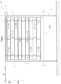
- the opening and closing body 2 includes a plurality of rod-shaped members 20 extending in the first direction X and arranged at an interval in a guide direction DR extending along the guide path R, and a plurality of coupling members 21 disposed in the guide direction DR and configured to couple the plurality of rod-shaped members 20.
- the plurality of rod-shaped members 20 are coupled together by the plurality of coupling members 21, thus forming the opening and closing body 2.
- the coupling members 21 are coupled to a plurality of locations of each of the plurality of rod-shaped members 20 in the first direction X.
- the size of the opening and closing body 2 in the guide direction DR is smaller than the size of the guide path R (or the guide rail 1) in the guide direction DR. Therefore, a region in which the rod-shaped members 20 and the coupling members 21, or in other words, the opening and closing body 2 is not present is present in a portion of the guide path R. Accordingly, the second region R2 of the guide path R is opened when the opening and closing body 2 is in the first state. Also, the first region R1 of the guide path R is opened when the opening and closing body 2 is in the second state.
- each of the two guide rails 1 includes a guide groove 10 extending in the guide direction DR.
- Each of the guide grooves 10 is opened toward the inner side of the corresponding guide rail 1 in the first direction X (the side on which the other guide rail 1 is disposed).
- Guided portions 20e are provided at opposite end portions of each of the rod-shaped members 20 in the first direction X.
- Each of the guided portions 20e is supported by the corresponding guide groove 10 in such a manner as to be movable in the guide direction DR.
- the guided portion 20e is formed using a roller.
- each of the coupling members 21 includes a pair of fitting parts 211 that are spaced apart in the guide direction DR and configured to be fitted to a coupling target pair of rod-shaped members 20 that are adjacent to each other in the guide direction DR. More specifically, each of the coupling members 21 includes a body part 210 extending in the guide direction DR, and fitting parts 211 formed at opposite end portions of the body part 210 in the guide direction DR. In the present embodiment, the body part 210 is formed in a band shape having a surface extending in the guide direction DR and the first direction X (see also Fig. 7 ).
- each of the plurality of rod-shaped members 20 in the first direction X are respectively attached to the pair of guide rails 1, thereby arranging the plurality of rod-shaped members 20 in the guide direction DR.
- the pair of fitting parts 211 of the corresponding coupling member 21 are fitted to a coupling target pair of rod-shaped members 20 that are adjacent to each other in the guide direction DR, thereby coupling the pair of rod-shaped members 20 that are adjacent to each other in the guide direction DR.
- the plurality of rod-shaped members 20 can be sequentially attached to the pair of guide rails 1. Accordingly, an assembly operation can be performed without the need of a wide space, unlike the case where one large opening and closing body is attached to the pair of guide rails. Furthermore, this assembly operation is performed in separate steps for each member, and therefore the number of workers can be easily reduced.
- Each of the fitting parts 211 includes a cover part 211c having flexibility and configured to cover a range of an outer circumferential surface 20f of the fitted rod-shaped member 20, the range being smaller than a circumference of the outer circumferential surface 20f and larger than half the circumference as viewed in the first direction X.
- Each of the cover parts 211c has a shape formed by cutting out a part (specifically, a region smaller than a half circumference of the outer circumferential surface 20f) of a tubular portion surrounding the outer circumferential surface 20f of the rod-shaped member 20, as viewed in the first direction X.
- the cover part 211c of each of the fitting parts 211 has flexibility. Accordingly, when the fitting part 211 is pressed against the corresponding rod-shaped member 20 from a direction orthogonal to the first direction X to be fitted thereto, it is possible to temporarily enlarge a cut-out part 211n, where the cover part 211c is not formed, of the fitting part 211, thereby inserting the rod-shaped member 20 inside the cover part 211c. Also, the cover part 211c covers a range of the outer circumferential surface 20f of the rod-shaped member 20, the range being smaller than a circumference of the outer circumferential surface 20f and larger than half the circumference as viewed in the first direction X. Accordingly, after the rod-shaped member 20 has been fitted to the fitting part 211, the coupling member 21 is unlikely to be detached from the rod-shaped member 20.
- each of the rod-shaped members 20 is formed by a solid or hollow round rod member, and the outer circumferential surface 20f is formed in a cylindrical shape.
- Each cover part 211c comes into contact with the outer circumferential surface 20f of the rod-shaped member 20 from outside, and covers a range of the outer circumferential surface 20f that is smaller than a circumference of the outer circumferential surface 20f and larger than half the circumference.
- the outer circumferential surface 20f of each rod-shaped member 20 is formed in a cylindrical shape.
- the cover part 211c is configured to cover the cylindrical outer circumferential surface 20f over a range spanning more than 180° and less than 360° of the outer circumferential surface 20f as viewed in the first direction X.
- the cover part 211c includes an inner circumferential surface 211f having a shape corresponding to the shape of the outer circumferential surface 20f. This can increase the area of contact of the cover part 211c with the outer circumferential surface 20f of the rod-shaped member 20, thus making it possible to firmly fitting the fitting part 211 to the rod-shaped member 20.
- the outer circumferential surface 20f of the rod-shaped member 20 is formed in a cylindrical shape. Therefore, the inner circumferential surface 211f of the cover part 211c is formed in a circular arc shape as viewed in the first direction X.
- the cover part 211c has a shape formed by cutting out a circumferential portion (specifically, a circumferential region spanning less than 180°) of a cylindrical shape surrounding the outer circumferential surface 20f of the rod-shaped member 20.
- the plurality of coupling members 21 are arranged in the guide direction DR while positions of the coupling members 21 in the first direction X are alternated with each other.
- the respective fitting parts 211 of two coupling members 21 that are adjacent to each other in the guide direction DR are disposed in such a manner as to be fitted to the same rod-shaped member 20 and to be adjacent to each other in the first direction X.
- all of the plurality of coupling members 21 that are arranged in the guide direction DR are disposed while positions of the coupling members 21 in the first direction X are alternated with each other.
- two fitting parts 211 that are fitted to the same rod-shaped member 20 and that are adjacent to each other in the first direction X abut against each other in the first direction X. Accordingly, two coupling members 21 that are adjacent to each other in the guide direction DR, which correspond to the two fitting parts 211 that are adjacent to each other in the first direction X, can be easily handled as an integral structure. Therefore, it is possible to further facilitate an operation of assembling the shutter 100.
- the opening and closing body 2 includes restriction members 22.
- the restriction members 22 are provided so as not to move in the first direction X relative to the corresponding rod-shaped members 20 and configured to restrict the coupling members 21 from moving in the first direction X relative to the rod-shaped members 20.
- each of the restriction members 22 is a member separate from the rod-shaped members 20, and is configured to be attached to the rod-shaped members 20 from a direction orthogonal to the first direction X. Accordingly, the position of attachment of each of the restriction members 22 to the corresponding rod-shaped members 20 can be easily set freely. Therefore, after coupling each of the coupling members 21 to the corresponding rod-shaped member 20, the restriction member 22 can be attached to the rod-shaped member 20 according to the position of the coupling member 21.
- each of the restriction members 22 is formed using Insulok (registered trademark).
- the restriction members 22 are arranged in the guide direction DR while a position of each of the restriction members 22 in the first direction X relative to a fitting part set U including two of the fitting parts 211 that are fitted to the same rod-shaped member 20 and that are adjacent to each other in the first direction X is alternated between a position adjacent to the fitting part set U on the first direction-first side X1 and a position adjacent to the fitting part set U on the first direction-second side X2, for each of the plurality of rod-shaped members 20 arranged in the guide direction DR. That is, no restriction member 22 is disposed on the first direction-second side X2 of a fitting part set U for which a restriction member 22 is disposed on the first direction-first side X1 thereof. Similarly, no restriction member 22 is disposed on the first direction-first side X1 of a fitting part set U for which a restriction member 22 is disposed on the first direction-second side X2 thereof.
- a restriction member 22 is disposed on the first direction-second side X2 of the other fitting part set U.
- a restriction member 22 is disposed on the first direction-first side X1 of the other fitting part set U.
- a restriction member 22 is placed at only one of a position adjacent to the fitting part set U on the first direction-first side X1 and a position adjacent to the fitting part set U on the first direction-second side X2, whereby it is possible to restrict each of the plurality of fitting part sets U from moving to either the first direction-first side X1 or and the first direction-second side X2. Accordingly, it is possible to appropriately fix the coupling members 21 to the rod-shaped members 20, while keeping the number of restriction members 22 small.
- the shutter 100 includes a detection device 4 that detects an object passing through the first region R1 from the work area WA.
- the work area WA is provided on the second direction-first side Y1 relative to the first region R1 (see Figs. 2 and 3 ).
- the worker W can perform, from the work area WA, work on the article 9 placed on the article placement portion 8. However, in a situation where it is difficult to ensure the safety of the worker W, it is preferable that the above-described work is not performed by the worker W.
- the detection device 4 can detect the passage. In this case, for example, it is preferable to stop the transport of the article 9 in the transport area TA, or to alert the facility manager or the worker W by emitting an alarm sound.
- an "object" that is to be detected by the detection device 4 may be a work robot if the work robot is provided in the work area WA, or may be the article 9 or the like.
- the detection device 4 is configured to detect the object at plurality of locations in the first region R1 that are spaced apart in the vertical direction. In the present example, the detection device 4 is configured to detect the object also in the first arcuate region R10.
- the detection device 4 includes a first detector 41, a second detector 42, a third detector 43, a fourth detector 44, and a fifth detector 45 that are disposed at heights different from each other.
- the first detector 41, the second detector 42, the third detector 43, the fourth detector 44, and the fifth detector 45 are attached to the guide rails 1.
- the first detector 41, the second detector 42, the third detector 43, the fourth detector 44, and the fifth detector 45 are each formed using a photosensor including a light receiving part and a light projecting part, and projects detection light in the first direction X.
- the first detector 41 and the second detector 42 are configured to detect an object below a central portion of the first region R1 in the vertical direction.
- the first detector 41 is configured to detect an object at a height in the vicinity of the knees of the worker W.
- the second detector 42 is configured to detect an object at a height in the vicinity of the base of the legs of the worker W.
- the third detector 43 and the fourth detector 44 are configured to detect an object above a central portion of the first region R1 in the vertical direction.
- the third detector 43 is configured to detect an object at a height in the vicinity of the chest of the worker W.
- the fourth detector 44 is configured to detect an object at a height in the vicinity of the head of the worker W.
- the fifth detector 45 is configured to detect an object in the first arcuate region R10.
- the fifth detector 45 can detect an object trapped by the opening and closing body 2 that is retracted upward from the first region R1.
- the shutter 100 described above allows an assembly operation to be performed relatively easily even when including a large opening and closing body 2.
- Fig. 9 is a perspective view of a coupling member 21 as viewed from the front surface side thereof.
- Fig. 10 is a perspective view of the coupling member 21 as viewed from the back surface side thereof.
- the "front surface” is a surface of a coupling member 21 that faces the outside of the shutter 100, while the coupling member 21 is attached to a rod-shaped member 20.
- the “back surface” is a surface of a coupling member 21 that faces the inside of the shutter 100 (the space surrounded by the shutter 100), while the coupling member 21 is attached to a rod-shaped member 20.
- the transport area TA and the work area WA are provided outside the shutter 100, and the article placement portion 8 is provided inside the shutter 100.
- each of the coupling members 21 includes a body part 210 extending in the guide direction DR, and fitting parts 211 formed at opposite end portions of the body part 210 in the guide direction DR.
- the pair of fitting parts 211 have shapes different from each other, and have complementary shapes.
- a plurality of coupling members 21 are arranged in the guide direction DR while positions of the coupling members 21 in the first direction X are alternated with each other in the first embodiment described above, a plurality of coupling members 21 are arranged in the guide direction DR at the same position in the first direction X in the present embodiment.
- a first fitting part 211A refers to one of the two fitting parts 211 of each of the coupling members 21, and a second fitting part 211B refers to the other of the two fitting parts 211.
- the first fitting part 211A and the second fitting part 211B have complementary shapes. Specifically, the first fitting part 211A and the second fitting part 211B have complementary shapes as viewed in a direction orthogonal to both the first direction X and the guide direction DR (see Fig. 11 ).
- the number of cover parts 211c that the first fitting part 211A includes, and the number of cover parts 211c that the second fitting part 211B includes are different.
- the first fitting part 211A includes one cover part 211c
- the second fitting part 211B includes two cover parts 211c.
- the cover part 211c of the first fitting part 211A and the cover parts 211c of the second fitting part 211B are disposed at different positions in the first direction X.
- the cover part 211c of the first fitting part 211A and the cover parts 211c of the second fitting part 211B are disposed at different positions in the first direction X within a predetermined width Lx described below (see Fig. 11 ).
- the cover part 211c of the first fitting part 211A is provided at a central portion of the body part 210 in the first direction X.
- the pair of cover parts 211c of the second fitting part 211B are provided at opposite end portions of the body part 210 in the first direction X.
- Each of the plurality of coupling members 21 arranged in the guide direction DR is disposed facing the same side in the guide direction DR. Specifically, each of the plurality of coupling members 21 is disposed such that the first fitting part 211A faces one side in the guide direction DR, and the second fitting part 211B faces the other side in the guide direction DR.
- the respective fitting parts 211 of a pair of coupling members 21 that are adjacent to each other in the guide direction DR are fitted to the same rod-shaped member 20. That is, the first fitting part 211A of one of the two coupling members 21, and the second fitting part 211B of the other coupling member 21 are fitted to the same rod-shaped member 20. However, only one of the first fitting part 211A and the second fitting part 211B is fitted to the two rod-shaped members 20 (target rod-shaped members 20T described below) disposed at opposite ends in the guide direction DR among all of the rod-shaped members 20.
- the cover part 211c of the first fitting part 211A is provide at a central portion of the body part 210 in the first direction X.
- the pair of parts 211c of the second fitting part 211B are provided at opposite end portions of the body part 210 in the first direction X. Accordingly, the cover part 211c of the first fitting part 211A and the pair of cover parts 211c of the second fitting part 211B are disposed adjacent to each other in the first direction X on the same rod-shaped member 20.
- the first fitting part 211A and the second fitting part 211B have complementary shapes in such a configuration.
- the first fitting part 211A of the first coupling member 21A and the second fitting part 211B of the second coupling member 21B that are fitted to the same rod-shaped member 20 are disposed in such a manner as to be fitted to each other in the first direction X.
- the first fitting part 211A of the second coupling member 21B and the second fitting part 211B of the first coupling member 21A that are fitted to the same rod-shaped member 20 are disposed in such a manner as to be fitted to each other in the first direction X.
- each of the coupling members 21 includes at least one reinforcing rib 210a protruding from the body part 210 to the front surface side or the back surface side.
- the reinforcing rib 210a is formed protruding from the body part 210 to the back surface side.
- the reinforcing rib 210a is formed extending in the guide direction DR.
- a pair of reinforcing ribs 210a disposed parallel to each other are formed on the back surface side of the body part 210.
- a first coupling member 21A is one of two coupling members 21 that are adjacent to each other in the guide direction DR
- a second coupling member 21B is the other of the two coupling members 21.
- the first coupling member 21A and the second coupling member 21B are coupled to the same rod-shaped member 20.
- the first fitting part 211A of the first coupling member 21A and the second fitting part 211B of the second coupling member 21B are fitted to each of the plurality of rod-shaped members 20, or the second fitting part 211B of the first coupling member 21A and the first fitting part 211A of the second coupling member 21B are fitted to each of the plurality of rod-shaped members 20.
- the first fitting part 211A and the second fitting part 211B are disposed adjacent to each other in the first direction X on the same rod-shaped member 20.
- at least one of the first fitting part 211A and the second fitting part 211B is formed in such a manner as to sandwich at least a portion of the other from opposite sides in the first direction X.
- the second fitting part 211B is formed in such a manner as to sandwich the first fitting part 211A from opposite sides in the first direction X on the same rod-shaped member 20.
- the pair of cover parts 211c of each of the second fitting parts 211B are formed in such a manner as to sandwich the cover part 211c of the corresponding first fitting part 211A from opposite sides in the first direction X.
- the pair of cover parts 211c of the second fitting part 211B and the cover part 211c of the first fitting part 211A are disposed adjacent to each other in the first direction X on the same rod-shaped member 20 and alternately in the first direction X.
- target rod-shaped members 20T are the two rod-shaped members 20 disposed at opposite ends in the guide direction DR among all of the rod-shaped members 20.
- the restriction members 22 are provided only on the two target rod-shaped members 20T, and are disposed on each of the target rod-shaped members 20T in such a manner as to sandwich, from opposite sides in the first direction X, the first fitting part 211A or the second fitting part 211B that is fitted to the corresponding target rod-shaped member 20T.
- No restriction member 22 is disposed on the rod-shaped members 20 other than the target rod-shaped members 20T.
- each of the plurality of coupling members 21 that are arranged in the guide direction DR is disposed facing the same side in the guide direction DR. Accordingly, the first fitting part 211A is fitted to the target rod-shaped member 20T disposed at one end in the guide direction DR, and the second fitting part 211B is fitted to the target rod-shaped member 20T disposed at the other end, among all of the rod-shaped members 20.
- the first fitting part 211A that is fitted to one of the target rod-shaped members 20T includes one cover part 211c. Restriction members 22 are disposed on opposite sides of the cover part 211c of the first fitting part 211A in the first direction X.
- the second fitting part 211B that is fitted to the other target rod-shaped member 20T includes a pair of cover parts 211c.
- a restriction member 22 is disposed outward of each of the two cover parts 211c of the second fitting part 211B in the first direction X.
- No restriction member 22 is disposed inward of each of the two cover parts 211c in the first direction X.
- the plurality of first coupling members 21A and the plurality of second coupling members 21B that are arranged in the guide direction DR are, as a whole, formed in a band shape extending in the guide direction DR within a predetermined width Lx in the first direction X.
- the "predetermined width Lx" corresponds to the size of the body part 210 of the coupling member 21 in the first direction X.
- the predetermined width Lx is comparable to the size of the body part 210 in the first direction X (design errors or the like are tolerated).
- the first fitting part 211A and the second fitting part 211B that are fitted to the same rod-shaped member 20 are disposed within the predetermined width Lx.
- the cover part 211c of the first fitting part 211A and the pair of cover parts 211c of the second fitting part 211B are disposed adjacent to each other in the first direction X within the predetermined width Lx on the same rod-shaped member 20.
- a shutter including: a pair of guide rails spaced apart in a first direction extending in a horizontal direction; a guide path extending in an extension direction of the pair of guide rails at a position between the pair of guide rails in the first direction; and an opening and closing body configured to move along the guide path, wherein the opening and closing body includes a plurality of rod-shaped members extending in the first direction and arranged at an interval in a guide direction extending along the guide path, and a plurality of coupling members disposed in the guide direction and configured to couple the plurality of rod-shaped members, opposite end portions of each of the plurality of rod-shaped members in the first direction are respectively guided by the pair of guide rails in such a manner as to be movable in the guide direction, each of the coupling members includes a pair of fitting parts that are spaced apart in the guide direction and configured to be fitted to a coupling target pair of rod-shaped members that are adjacent to each other in the guide direction, and each of the fitting parts includes
- the opening and closing body includes a plurality of rod-shaped members and a plurality of coupling members.
- opposite end portions of each of the plurality of rod-shaped members in the first direction X are respectively attached to a pair of guide rails, thereby arranging the plurality of rod-shaped members in the guide direction.
- a pair of fitting parts of each of the corresponding coupling member are fitted to a coupling target pair of the rod-shaped members that are adjacent to each other in the guide direction, thereby coupling the pair of rod-shaped members that are adjacent to each other in the guide direction.
- the plurality of rod-shaped members can be sequentially attached to the pair of guide rails.
- the cover part covers a range of the outer circumferential surface of the rod-shaped member, the range being smaller than a circumference of the outer circumferential surface and larger than half the circumference as viewed in the first direction. Accordingly, after the rod-shaped member has been fitted to the fitting part, the coupling member is unlikely to be detached from the rod-shaped member. Therefore, the plurality of rod-shaped members can be coupled through a simple operation, thereby forming the opening and closing body. As described above, this configuration makes it possible to realize a shutter that allows an assembly operation to be performed relatively easily even when including a large opening and closing body.
- first fitting part being one of the two fitting parts of each of the coupling members
- second fitting part being another one of the two fitting parts
- first coupling member being one of two of the coupling members that are adjacent to each other in the guide direction
- second coupling member being another one of the two adjacent coupling members
- the opening and closing body includes restriction members provided so as not to move in the first direction relative to the rod-shaped members and configured to restrict the coupling members from moving in the first direction relative to the rod-shaped members,
- first fitting part being one of the two fitting parts of each of the coupling members
- second fitting part being another one of the two fitting parts
- a first coupling member being one of two of the coupling members that are adjacent to each other in the guide direction
- a second coupling member being another one of the two adjacent coupling members
- the first fitting part and the second fitting part have complementary shapes
- the plurality of first coupling members and the plurality of second coupling members that are arranged in the guide direction are formed, as a whole, in a band shape extending in the guide direction within a predetermined width in the first direction, and the first fitting portion and the second fitting portion that are fitted to a corresponding rod-shaped member are disposed within the predetermined width.
- the region of the opening and closing body in which the plurality of coupling members are disposed in the first direction can be fitted within a predetermined width. Accordingly, if it is necessary to view the opposite side through the opening and closing body, the visibility can be easily ensured.
- the plurality of coupling members are arranged in the guide direction while positions of the coupling members in the first direction are alternated with each other, and respective fitting parts of two of the coupling members that are adjacent to each other in the guide direction are disposed in such a manner as to be fitted to a corresponding rod-shaped member and to be adjacent to each other in the first direction.
- the opening and closing body includes restriction members provided so as not to move in the first direction relative to the rod-shaped members and configured to restrict the coupling members from moving in the first direction relative to the rod-shaped members, the restriction members are arranged in the guide direction while a position of each of the restriction members in the first direction relative to a fitting part set including two of the fitting parts that are fitted to the same rod-shaped member and that are adjacent to each other in the first direction is alternated between a position adjacent to the fitting part set on a first side in the first direction and a position adjacent to the fitting part set on a second side in the first direction, for each of the plurality of rod-shaped members arranged in the guide direction.
- a restriction member is placed at only one of a position adjacent to the fitting part set on the first direction-first side and a position adjacent to the fitting part set on the first direction-second side, whereby it is possible to restrict each of the plurality of fitting part sets from moving to either the first direction-first side or the first direction-second side. Accordingly, it is possible to appropriately fix the coupling members to the rod-shaped members, while keeping the number of restriction members small.
- the guide path includes a first region extending in a vertical direction, a ceiling region above the first region and extending in a second direction orthogonal to the first direction as viewed in the vertical direction, and a first arcuate region formed in an arcuate shape as viewed in the first direction in such a manner as to connect an upper end portion of the first region and an end portion of the ceiling region on a first side in the second direction, the guide path further includes a second region disposed spaced apart from the first region toward a second side in the second direction and extending in the vertical direction, and a second arcuate region formed in an arcuate shape as viewed in the first direction in such a manner as to connect an upper end portion of the second region and an end portion of the ceiling region on the second side in the second direction, and the opening and closing body is configured to change between a first state in which the opening and closing body is disposed over the first region, the first arcuate region, and the ceiling region, and is not disposed in the second region, and a second
- the opening and closing body can be selectively moved such that, when one of the first region and the second region is opened, the other is closed.
- an article placement portion on which an article is placeable is provided between the first region and the second region in the second direction, a work area in which work is performed on the article placed on the article placement portion is provided on the first side in the second direction relative to the first region, a transport area for transporting the article to the article placement portion is provided on the second side in the second direction relative to the second region, when the opening and closing body is in the first state, the second region is opened to enable the article to be transported from the transport area to the article placement portion, and, when the opening and closing body is in the second state, the first region is opened to enable work to be performed, from the work area, on the article placed on the article placement portion.
- a transport device that transports the article is provided in the transport area, the transport device is configured to transport the article to the article placement portion, in the work area, a worker performs work on the article placed on the article placement portion, and a scaffold for the worker is provided between the first region and the second region in the second direction in a region surrounding the article placement portion.
- the worker can use the scaffold provided in a region surrounding the article placement portion to perform work on the article placed on the article placement portion, or work such as maintenance of the surroundings of the article placement portion.
- the shutter further includes a detection device configured to detect an object passing through the first region from the work area, wherein the detection device is configured to detect the object at a plurality of locations in the first region that are spaced apart in the vertical direction.
- the detection device can detect the entry. If the detection device detects an object, it is possible, for example, to stop the transport of the article in the transport area, or to alert the facility manager or the worker by emitting an alarm sound.
- the technique according to the present invention is applicable to a shutter including a pair of guide rails spaced apart in a first direction extending in a horizontal direction, a guide path extending in an extension direction of the pair of guide rails between the pair of guide rails in the first direction, and an opening and closing body configured to move along the guide path.
Landscapes
- Engineering & Computer Science (AREA)
- Structural Engineering (AREA)
- Civil Engineering (AREA)
- Architecture (AREA)
- Transportation (AREA)
- Life Sciences & Earth Sciences (AREA)
- Geology (AREA)
- Mechanical Engineering (AREA)
- Operating, Guiding And Securing Of Roll- Type Closing Members (AREA)
- Blinds (AREA)
Claims (10)
- Grille roulante (100) comprenant :une paire de rails de guidage (1) espacés dans une première direction (X) s'étendant dans une direction horizontale ;une voie de guidage (R) s'étendant dans une direction d'étendue de la paire de rails de guidage (1) dans une position entre la paire de rails de guidage (1) dans la première direction (X) ; et un corps d'ouverture et de fermeture (2) configuré pour se déplacer le long de ladite voie de guidage (R),ledit corps d'ouverture et de fermeture (2) comportant une pluralité d'éléments en forme de tige (20) qui s'étendent dans la première direction (X) et sont disposés à un intervalle dans une direction de guidage (DR) s'étendant le long de la voie de guidage (R), et une pluralité d'éléments de couplage (21) disposés dans la direction de guidage (DR) et configurés pour coupler la pluralité d'éléments en forme de tige (20),des extrémités opposées de chacun de la pluralité d'éléments en forme de tige (20) dans la première direction (X) étant, respectivement, guidée par la paire de rails de guidage (1) de façon à être mobile dans la direction de guidage (DR),chacun des éléments de couplage (21) comportant une paire de raccords (211) qui sont espacés dans la direction de guidage (DR) et configurés pour être attachés à une paire d'éléments en forme de tige (20) cible de couplage qui sont adjacent l'un à l'autre dans la direction de guidage (DR), etchacun desdits raccords (211) comportant une partie de couverture (211c) qui est configurée pour couvrir un secteur d'une surface périphérique extérieure (20f) de l'élément en forme de tige (20) monté, le secteur étant inférieur à la circonférence de la surface périphérique extérieure (20f) et supérieur à la moitié de la circonférence vu dans la première direction (X)caractérisée en ce queladite partie de couverture (211c) de chacun desdits raccords (211) a une flexibilité permettant de le pousser contre l'élément en forme de tige (20) correspondant à partir d'une direction orthogonale à la première direction de manière à être attachés à celui-ci, en élargissant une partie découpée, où ladite partie de couverture (211c) n'est pas formée, du raccord (211) afin d'insérer ledit élément en forme de tige (20) dans ladite partie de couverture (211c).
- Grille roulante (100) selon la revendication 1, dans laquelle,un premier raccord (211A) étant un des deux raccords (211) de chacun des éléments de couplage (21), un deuxième raccord (211B) étant l'autre des deux raccords (211), un premier élément de couplage (21A) étant un des deux éléments de couplage (21) qui sont adjacent l'un à l'autre dans la direction de guidage (DR), et un deuxième élément de couplage (21B) étant l'autre des deux éléments de couplage (21) adjacents,le premier raccord (211A) et le deuxième raccord (211B) sont de forme complémentaire, et le premier raccord (211A) du premier élément de couplage (21A) et le deuxième raccord (211B) du deuxième élément de couplage (21B) qui sont attachés à un élément en forme de tige (20) correspondant sont disposés de façon qu'ils sont adaptés les uns aux autre dans la première direction (X).
- Grille roulante (100) selon la revendication 2, dans laquelleledit corps d'ouverture et de fermeture (2) comporte des éléments de restriction (22) qui sont prévus de façon à ne pas se déplacer dans la première direction (X) par rapport aux éléments en forme de tige (20) et configurés pour empêcher les éléments de couplage (21) de se déplacer dans la première direction (X) par rapport aux éléments en forme de tige (20),au moins un du premier raccord (211A) et du deuxième raccord (211B) prend en sandwich au moins une partie de l'autre du premier raccord (211A) et du deuxième raccord (211B) de côtés opposés dans la première direction (X), etlesdits éléments de restriction (22) ne sont prévus que sur des éléments en forme de tige (20T) ciblés qui sont les deux éléments en forme de tige (20) disposés sur des extrémités opposées dans la direction de guidage (DR) parmi tous les éléments en forme de tige (20), et lesdits éléments de restriction (22) sont disposés sur chacun des éléments en forme de tige (20T) ciblés de façon à prendre en sandwich, de côtés opposés dans la première direction (X), le premier raccord (211A) ou le deuxième raccord (211B) qui est attaché à l'élément en forme de tige (20T) ciblé.
- Grille roulante (100) selon la revendication 1, dans laquelleun premier raccord (211A) étant un des deux raccords (211) de chacun des éléments de couplage (21), un deuxième raccord (211B) étant l'autre des deux raccords (211), un premier élément de couplage (21A) étant un des deux éléments de couplage (21) qui sont adjacent l'un à l'autre dans la direction de guidage (DR), et un deuxième élément de couplage (21B) étant l'autre des deux éléments de couplage (21) adjacents,le premier raccord (211A) et le deuxième raccord (211B) sont de forme complémentaire, et la pluralité de premiers éléments de couplage (21A) et la pluralité de deuxièmes éléments de couplage (21B) qui sont disposés dans la direction de guidage (DR) sont formés, dans leur ensemble, en forme d'une bande s'étendant dans la direction de guidage (DR) dans une largeur prédéterminée (Lx) dans la première direction (X), etle premier raccord (211A) et le deuxième raccord (211B) qui sont attachés à un élément en forme de tige (20) correspondant sont disposés dans la largeur prédéterminée (Lx).
- Grille roulante (100) selon la revendication 1, dans laquellela pluralité d'éléments de couplage (21) sont disposés dans la direction de guidage (DR) alors que les positions des éléments de couplage (21) dans la première direction (X) sont alternées entre elles, etles raccords (211) respectifs de deux des éléments de couplage (21) qui sont adjacents l'un à l'autre dans la direction de guidage (DR) sont disposés de façon à être attachés à un élément en forme de tige (20) correspondant et à être adjacents l'un à l'autre dans la première direction (X).
- Grille roulante (100) selon la revendication 5, dans laquelleledit corps d'ouverture et de fermeture (2) comporte des éléments de restriction (22) qui sont prévus de façon à ne pas se déplacer dans la première direction (X) par rapport aux éléments en forme de tige (20) et configurés pour empêcher les éléments de couplage (21) de se déplacer dans la première direction (X) par rapport aux éléments en forme de tige (20),lesdits éléments de restriction (22) sont disposés dans la direction de guidage (DR) alors que la position de chacun des éléments de restriction (22) dans la première direction (X) par rapport à un ensemble (U) de raccords comportant deux des raccords (211) qui sont attachés au même élément en forme de tige (20) et qui sont adjacents l'un à l'autre dans la première direction (X) est alternée entre une position adjacente à l'ensemble (U) de raccords sur un premier côté (X1) dans la première direction (X) et une position adjacente à l'ensemble (U) de raccords sur un deuxième côté (X2) dans la première direction (X), pour chacun de la pluralité d'éléments en forme de tige (20) disposés dans la direction de guidage (DR).
- Grille roulante (100) selon l'une quelconque des revendications 1 à 6, dans laquellela voie de guidage (R) comporte une première région (R1) s'étendant dans une direction verticale, une région de plafond (RC) au-dessus de la première région (R1) et s'étendant dans une deuxième direction (Y) orthogonal à la première direction (X) vu en direction verticale, et une première région arquée (R10) formée en forme arquée vu dans la première direction (X) de façon à connecter une extrémité supérieure de la première région (R1) et une extrémité de la région de plafond (RC) sur un premier côté (Y1) dans la deuxième direction (Y),la voie de guidage (R) comporte une deuxième région (R2) espacée de la première région (R1) vers un deuxième côté (Y2) dans la deuxième direction (Y) et s'étendant en direction verticale, et une deuxième région arquée (R20) formée en forme arquée vu dans la première direction (X) de façon à connecter une extrémité supérieure de la deuxième région (R2) et une extrémité de la région de plafond (RC) sur un deuxième côté (Y2) dans la deuxième direction (Y), etledit corps d'ouverture et de fermeture (2) est configuré pour changer entre un premier état où le corps d'ouverture et de fermeture (2) est disposé sur la première région (R1), la première région arquée (R10) et la région de plafond (RC), et n'est pas disposé dans la deuxième région (R2), et un deuxième état où le corps d'ouverture et de fermeture (2) est disposé sur la région de plafond (RC), la deuxième région arquée (R20), et la deuxième région (R2), et n'est pas disposé dans la première région (R1).
- Grille roulante (100) selon la revendication 7, dans laquelleune partie de placement d'article (8) sur laquelle un article (9) peut être placé est prévue entre la première région (R1) et la deuxième région (R2) dans la deuxième direction (Y),une zone de travail (WA) dans laquelle du travail est effectué sur l'article (9) placé sur la partie de placement d'article (8) est prévue sur le premier côté (Y1) dans la deuxième direction (Y) par rapport à la première région (R1),une zone de transport (TA) pour transporter l'article (9) à la partie de placement d'article (8) est prévue sur le deuxième côté (Y2) dans la deuxième direction (Y) par rapport à la deuxième région (R2),lorsque le corps d'ouverture et de fermeture (2) est dans le premier état, la deuxième région (R2) est ouverte pour permettre que l'article (9) soit transporté de la zone de transport (TA) à la partie de placement d'article (8), etlorsque le corps d'ouverture et de fermeture (2) est dans le deuxième état, la première région (R1) est ouverte pour permettre que du travail soit effectué, à partir de la zone de transport (TA), sur l'article (9) placé sur la partie de placement d'article (8).
- Grille roulante (100) selon la revendication 8, dans laquelleun dispositif de transport (T) destiné à transporter l'article (9) est prévu dans la zone de transport (TA),le dispositif de transport (T) est configuré pour transporter l'article (9) à la partie de placement d'article (8),dans la zone de travail (WA), un travailleur (W) est destiné à effectuer du travail sur l'article (9) placé sur la partie de placement d'article (8), etun échafaudage (82) pour le travailleur (W) est prévu entre la première région (R1) et la deuxième région (R2) dans la deuxième direction (Y) dans une région entourant la partie de placement d'article (8).
- Grille roulante (100) selon la revendication 8 ou 9, comprenant en outreun dispositif de détection (4) configuré pour détecter un objet traversant la première région (R1) depuis la zone de travail (WA),le dispositif de détection (4) étant configuré pour détecter l'objet dans une pluralité d'endroits de la première région (R1) qui sont espacés dans la direction verticale.
Applications Claiming Priority (2)
| Application Number | Priority Date | Filing Date | Title |
|---|---|---|---|
| JP2021166953 | 2021-10-11 | ||
| JP2022077517A JP7589710B2 (ja) | 2021-10-11 | 2022-05-10 | シャッタ |
Publications (3)
| Publication Number | Publication Date |
|---|---|
| EP4170120A1 EP4170120A1 (fr) | 2023-04-26 |
| EP4170120B1 true EP4170120B1 (fr) | 2024-05-15 |
| EP4170120C0 EP4170120C0 (fr) | 2024-05-15 |
Family
ID=83690279
Family Applications (1)
| Application Number | Title | Priority Date | Filing Date |
|---|---|---|---|
| EP22200708.0A Active EP4170120B1 (fr) | 2021-10-11 | 2022-10-11 | Grille roulante |
Country Status (5)
| Country | Link |
|---|---|
| US (1) | US12534958B2 (fr) |
| EP (1) | EP4170120B1 (fr) |
| KR (1) | KR20230051756A (fr) |
| CN (1) | CN115961873A (fr) |
| ES (1) | ES2990250T3 (fr) |
Families Citing this family (1)
| Publication number | Priority date | Publication date | Assignee | Title |
|---|---|---|---|---|
| WO2023157588A1 (fr) * | 2022-02-15 | 2023-08-24 | 村田機械株式会社 | Étagère d'articles |
Family Cites Families (17)
| Publication number | Priority date | Publication date | Assignee | Title |
|---|---|---|---|---|
| FR789021A (fr) * | 1934-11-16 | 1935-10-22 | L Invulnerabile Sa | Store roulant à claire-voie à barres tubulaires horizontales |
| FR992503A (fr) * | 1949-05-30 | 1951-10-19 | Fermetures Metalliques Du Bati | Grille roulante |
| CH348541A (de) * | 1956-06-30 | 1960-08-31 | Karl Tuebinger Kg | Schutzgitter, insbesondere für Schaufenster |
| US3601175A (en) * | 1969-08-18 | 1971-08-24 | Cookson Co | Articulated grille |
| US3850465A (en) * | 1973-11-19 | 1974-11-26 | Cookson Co | Self-acting lock for articulated, rolling grilles |
| JPH044464Y2 (fr) | 1985-11-29 | 1992-02-10 | ||
| FR2621068B1 (fr) * | 1987-09-28 | 1991-08-30 | Lebihan Lemouel Sa Ets | Tablier de grille de fermeture a enroulement |
| JP2001115761A (ja) | 1999-10-18 | 2001-04-24 | Komatsu Denki Sangyo Kk | シートシャッターの下降規制センサ構造 |
| US6240997B1 (en) * | 1999-11-16 | 2001-06-05 | Ming-Kun Lee | Rolling steel door |
| US6189593B1 (en) * | 2000-02-09 | 2001-02-20 | Cornell Iron Works, Inc. | Injection molded roll up security closure |
| SG142163A1 (en) | 2001-12-05 | 2008-05-28 | Semiconductor Energy Lab | Organic semiconductor element |
| US6742563B2 (en) * | 2002-07-25 | 2004-06-01 | Dynamic Closures Corp. | Keyless rolling grille |
| DE102007050334A1 (de) * | 2007-10-18 | 2009-04-23 | Efaflex Tor- Und Sicherheitssysteme Gmbh & Co. Kg | Verfahren und Einrichtung zur Steuerung eines vertikal oder horizontal bewegten Tores unter Absicherung der Torschließebene gegenüber Hindernissen |
| DK2506034T3 (da) * | 2011-04-01 | 2013-09-02 | Cedes Ag | Sensorindretning, sikkerhedsindretning, dør og fremgangsmåde til kontrol af bevægelsen |
| DE102015101017B4 (de) * | 2015-01-23 | 2018-02-22 | Efaflex Tor- Und Sicherheitssysteme Gmbh & Co. Kg | Verfahren zur Steuerung einer Toranordnung sowie derartige Toranordnung und eine Sicherheitseinrichtung hierfür |
| ES2653517T3 (es) * | 2015-02-06 | 2018-02-07 | Masinara S.P.A. | Elemento de cierre para persiana de rodillo y pared móvil para persiana de rodillo que comprende el elemento de cierre |
| WO2020237062A1 (fr) * | 2019-05-21 | 2020-11-26 | Cornellcookson, Llc | Liaison de remplacement pour une enceinte de gril à enroulement et procédé associé |
-
2022
- 2022-09-29 KR KR1020220124007A patent/KR20230051756A/ko active Pending
- 2022-10-10 US US17/962,744 patent/US12534958B2/en active Active
- 2022-10-11 ES ES22200708T patent/ES2990250T3/es active Active
- 2022-10-11 EP EP22200708.0A patent/EP4170120B1/fr active Active
- 2022-10-11 CN CN202211240465.5A patent/CN115961873A/zh active Pending
Also Published As
| Publication number | Publication date |
|---|---|
| CN115961873A (zh) | 2023-04-14 |
| EP4170120A1 (fr) | 2023-04-26 |
| ES2990250T3 (es) | 2024-11-29 |
| US12534958B2 (en) | 2026-01-27 |
| US20230110733A1 (en) | 2023-04-13 |
| KR20230051756A (ko) | 2023-04-18 |
| EP4170120C0 (fr) | 2024-05-15 |
Similar Documents
| Publication | Publication Date | Title |
|---|---|---|
| AU2021325730B2 (en) | A grid framework structure | |
| JP6874161B2 (ja) | モジュール式保管システムおよび方法 | |
| KR20210107766A (ko) | 트랜스퍼 로봇, 창고 물류 시스템 및 물품 운반 방법 | |
| EP4170120B1 (fr) | Grille roulante | |
| CA3201350A1 (fr) | Recipient de stockage, systeme comprenant un ou plusieurs des recipients de stockage et procedes d'assemblage des recipients de stockage | |
| KR100632962B1 (ko) | 겹침식 셀터 시스템 | |
| JP2023505355A (ja) | 軌道システム上で動作不良車両を荷役するための方法およびそのような方法を使用する倉庫システム | |
| EP3296232A1 (fr) | Conteneur pliable et appareil d'ouverture et de fermeture de celui-ci | |
| US20210214161A1 (en) | Method for handling malfunctioning vehicles on a rail system and a storage and retrieval system using such a method | |
| KR20220027184A (ko) | 장벽을 포함하는 자동화된 저장 및 회수 시스템 | |
| US20240025457A1 (en) | System for storing and transporting storage containers | |
| JP7589710B2 (ja) | シャッタ | |
| CN105655274B (zh) | 物品保管设备 | |
| CA3208907A1 (fr) | Systeme de stockage automatise | |
| KR20240054337A (ko) | 그리드 프레임워크 구조물 | |
| CA2937669A1 (fr) | Systeme de rangement et extraction de palettes automatises | |
| US20240295081A1 (en) | A Grid Framework Structure | |
| US8210419B1 (en) | Hideaway doors for a workstation | |
| WO2024042534A1 (fr) | Équipement robotique pour le chargement et le déchargement de bouteilles de gaz et procédé associé | |
| JP5046016B2 (ja) | 物品処理場における遮蔽装置 | |
| JP6489047B2 (ja) | 物品搬送装置 | |
| JPH0138084Y2 (fr) | ||
| JP5447109B2 (ja) | 防火シャッタ、防火シャッタの据え付け方法 | |
| JPH04261904A (ja) | 隙間を橋渡しするための横断構造体を組立るための装置 | |
| JP6287699B2 (ja) | 物品搬送装置 |
Legal Events
| Date | Code | Title | Description |
|---|---|---|---|
| PUAI | Public reference made under article 153(3) epc to a published international application that has entered the european phase |
Free format text: ORIGINAL CODE: 0009012 |
|
| STAA | Information on the status of an ep patent application or granted ep patent |
Free format text: STATUS: THE APPLICATION HAS BEEN PUBLISHED |
|
| AK | Designated contracting states |
Kind code of ref document: A1 Designated state(s): AL AT BE BG CH CY CZ DE DK EE ES FI FR GB GR HR HU IE IS IT LI LT LU LV MC ME MK MT NL NO PL PT RO RS SE SI SK SM TR |
|
| RAP3 | Party data changed (applicant data changed or rights of an application transferred) |
Owner name: DAIFUKU CO., LTD. |
|
| RIN1 | Information on inventor provided before grant (corrected) |
Inventor name: NAKASHIMA, KOUICHIROU Inventor name: MIYAHARA, AKIRA |
|
| STAA | Information on the status of an ep patent application or granted ep patent |
Free format text: STATUS: REQUEST FOR EXAMINATION WAS MADE |
|
| 17P | Request for examination filed |
Effective date: 20231006 |
|
| RBV | Designated contracting states (corrected) |
Designated state(s): AL AT BE BG CH CY CZ DE DK EE ES FI FR GB GR HR HU IE IS IT LI LT LU LV MC ME MK MT NL NO PL PT RO RS SE SI SK SM TR |
|
| GRAP | Despatch of communication of intention to grant a patent |
Free format text: ORIGINAL CODE: EPIDOSNIGR1 |
|
| STAA | Information on the status of an ep patent application or granted ep patent |
Free format text: STATUS: GRANT OF PATENT IS INTENDED |
|
| INTG | Intention to grant announced |
Effective date: 20231208 |
|
| GRAS | Grant fee paid |
Free format text: ORIGINAL CODE: EPIDOSNIGR3 |
|
| GRAA | (expected) grant |
Free format text: ORIGINAL CODE: 0009210 |
|
| STAA | Information on the status of an ep patent application or granted ep patent |
Free format text: STATUS: THE PATENT HAS BEEN GRANTED |
|
| AK | Designated contracting states |
Kind code of ref document: B1 Designated state(s): AL AT BE BG CH CY CZ DE DK EE ES FI FR GB GR HR HU IE IS IT LI LT LU LV MC ME MK MT NL NO PL PT RO RS SE SI SK SM TR |
|
| REG | Reference to a national code |
Ref country code: CH Ref legal event code: EP |
|
| REG | Reference to a national code |
Ref country code: IE Ref legal event code: FG4D |
|
| REG | Reference to a national code |
Ref country code: DE Ref legal event code: R096 Ref document number: 602022003486 Country of ref document: DE |
|
| U01 | Request for unitary effect filed |
Effective date: 20240614 |
|
| U07 | Unitary effect registered |
Designated state(s): AT BE BG DE DK EE FI FR IT LT LU LV MT NL PT SE SI Effective date: 20240625 |
|
| PG25 | Lapsed in a contracting state [announced via postgrant information from national office to epo] |
Ref country code: IS Free format text: LAPSE BECAUSE OF FAILURE TO SUBMIT A TRANSLATION OF THE DESCRIPTION OR TO PAY THE FEE WITHIN THE PRESCRIBED TIME-LIMIT Effective date: 20240915 |
|
| PG25 | Lapsed in a contracting state [announced via postgrant information from national office to epo] |
Ref country code: HR Free format text: LAPSE BECAUSE OF FAILURE TO SUBMIT A TRANSLATION OF THE DESCRIPTION OR TO PAY THE FEE WITHIN THE PRESCRIBED TIME-LIMIT Effective date: 20240515 |
|
| PG25 | Lapsed in a contracting state [announced via postgrant information from national office to epo] |
Ref country code: GR Free format text: LAPSE BECAUSE OF FAILURE TO SUBMIT A TRANSLATION OF THE DESCRIPTION OR TO PAY THE FEE WITHIN THE PRESCRIBED TIME-LIMIT Effective date: 20240816 |
|
| PG25 | Lapsed in a contracting state [announced via postgrant information from national office to epo] |
Ref country code: PL Free format text: LAPSE BECAUSE OF FAILURE TO SUBMIT A TRANSLATION OF THE DESCRIPTION OR TO PAY THE FEE WITHIN THE PRESCRIBED TIME-LIMIT Effective date: 20240515 |
|
| PG25 | Lapsed in a contracting state [announced via postgrant information from national office to epo] |
Ref country code: PL Free format text: LAPSE BECAUSE OF FAILURE TO SUBMIT A TRANSLATION OF THE DESCRIPTION OR TO PAY THE FEE WITHIN THE PRESCRIBED TIME-LIMIT Effective date: 20240515 Ref country code: NO Free format text: LAPSE BECAUSE OF FAILURE TO SUBMIT A TRANSLATION OF THE DESCRIPTION OR TO PAY THE FEE WITHIN THE PRESCRIBED TIME-LIMIT Effective date: 20240815 Ref country code: IS Free format text: LAPSE BECAUSE OF FAILURE TO SUBMIT A TRANSLATION OF THE DESCRIPTION OR TO PAY THE FEE WITHIN THE PRESCRIBED TIME-LIMIT Effective date: 20240915 Ref country code: HR Free format text: LAPSE BECAUSE OF FAILURE TO SUBMIT A TRANSLATION OF THE DESCRIPTION OR TO PAY THE FEE WITHIN THE PRESCRIBED TIME-LIMIT Effective date: 20240515 Ref country code: GR Free format text: LAPSE BECAUSE OF FAILURE TO SUBMIT A TRANSLATION OF THE DESCRIPTION OR TO PAY THE FEE WITHIN THE PRESCRIBED TIME-LIMIT Effective date: 20240816 Ref country code: RS Free format text: LAPSE BECAUSE OF FAILURE TO SUBMIT A TRANSLATION OF THE DESCRIPTION OR TO PAY THE FEE WITHIN THE PRESCRIBED TIME-LIMIT Effective date: 20240815 |
|
| U20 | Renewal fee for the european patent with unitary effect paid |
Year of fee payment: 3 Effective date: 20241007 |
|
| REG | Reference to a national code |
Ref country code: ES Ref legal event code: FG2A Ref document number: 2990250 Country of ref document: ES Kind code of ref document: T3 Effective date: 20241129 |
|
| PG25 | Lapsed in a contracting state [announced via postgrant information from national office to epo] |
Ref country code: CZ Free format text: LAPSE BECAUSE OF FAILURE TO SUBMIT A TRANSLATION OF THE DESCRIPTION OR TO PAY THE FEE WITHIN THE PRESCRIBED TIME-LIMIT Effective date: 20240515 |
|
| PG25 | Lapsed in a contracting state [announced via postgrant information from national office to epo] |
Ref country code: SK Free format text: LAPSE BECAUSE OF FAILURE TO SUBMIT A TRANSLATION OF THE DESCRIPTION OR TO PAY THE FEE WITHIN THE PRESCRIBED TIME-LIMIT Effective date: 20240515 Ref country code: RO Free format text: LAPSE BECAUSE OF FAILURE TO SUBMIT A TRANSLATION OF THE DESCRIPTION OR TO PAY THE FEE WITHIN THE PRESCRIBED TIME-LIMIT Effective date: 20240515 |
|
| PG25 | Lapsed in a contracting state [announced via postgrant information from national office to epo] |
Ref country code: SM Free format text: LAPSE BECAUSE OF FAILURE TO SUBMIT A TRANSLATION OF THE DESCRIPTION OR TO PAY THE FEE WITHIN THE PRESCRIBED TIME-LIMIT Effective date: 20240515 |
|
| PG25 | Lapsed in a contracting state [announced via postgrant information from national office to epo] |
Ref country code: SM Free format text: LAPSE BECAUSE OF FAILURE TO SUBMIT A TRANSLATION OF THE DESCRIPTION OR TO PAY THE FEE WITHIN THE PRESCRIBED TIME-LIMIT Effective date: 20240515 Ref country code: SK Free format text: LAPSE BECAUSE OF FAILURE TO SUBMIT A TRANSLATION OF THE DESCRIPTION OR TO PAY THE FEE WITHIN THE PRESCRIBED TIME-LIMIT Effective date: 20240515 Ref country code: RO Free format text: LAPSE BECAUSE OF FAILURE TO SUBMIT A TRANSLATION OF THE DESCRIPTION OR TO PAY THE FEE WITHIN THE PRESCRIBED TIME-LIMIT Effective date: 20240515 Ref country code: CZ Free format text: LAPSE BECAUSE OF FAILURE TO SUBMIT A TRANSLATION OF THE DESCRIPTION OR TO PAY THE FEE WITHIN THE PRESCRIBED TIME-LIMIT Effective date: 20240515 |
|
| REG | Reference to a national code |
Ref country code: DE Ref legal event code: R097 Ref document number: 602022003486 Country of ref document: DE |
|
| PLBE | No opposition filed within time limit |
Free format text: ORIGINAL CODE: 0009261 |
|
| STAA | Information on the status of an ep patent application or granted ep patent |
Free format text: STATUS: NO OPPOSITION FILED WITHIN TIME LIMIT |
|
| 26N | No opposition filed |
Effective date: 20250218 |
|
| PG25 | Lapsed in a contracting state [announced via postgrant information from national office to epo] |
Ref country code: MC Free format text: LAPSE BECAUSE OF FAILURE TO SUBMIT A TRANSLATION OF THE DESCRIPTION OR TO PAY THE FEE WITHIN THE PRESCRIBED TIME-LIMIT Effective date: 20240515 |
|
| U20 | Renewal fee for the european patent with unitary effect paid |
Year of fee payment: 4 Effective date: 20250909 |
|
| PG25 | Lapsed in a contracting state [announced via postgrant information from national office to epo] |
Ref country code: IE Free format text: LAPSE BECAUSE OF NON-PAYMENT OF DUE FEES Effective date: 20241011 |
|
| REG | Reference to a national code |
Ref country code: CH Ref legal event code: U11 Free format text: ST27 STATUS EVENT CODE: U-0-0-U10-U11 (AS PROVIDED BY THE NATIONAL OFFICE) Effective date: 20251101 |
|
| PGFP | Annual fee paid to national office [announced via postgrant information from national office to epo] |
Ref country code: CH Payment date: 20251101 Year of fee payment: 4 |
|
| PG25 | Lapsed in a contracting state [announced via postgrant information from national office to epo] |
Ref country code: CY Free format text: LAPSE BECAUSE OF FAILURE TO SUBMIT A TRANSLATION OF THE DESCRIPTION OR TO PAY THE FEE WITHIN THE PRESCRIBED TIME-LIMIT; INVALID AB INITIO Effective date: 20221011 |
|
| PGFP | Annual fee paid to national office [announced via postgrant information from national office to epo] |
Ref country code: ES Payment date: 20251103 Year of fee payment: 4 |
|
| PG25 | Lapsed in a contracting state [announced via postgrant information from national office to epo] |
Ref country code: HU Free format text: LAPSE BECAUSE OF FAILURE TO SUBMIT A TRANSLATION OF THE DESCRIPTION OR TO PAY THE FEE WITHIN THE PRESCRIBED TIME-LIMIT; INVALID AB INITIO Effective date: 20221011 |