EP4170132A1 - Pale pour une turbomachine, ainsi que procédé de fabrication d'une pale, la pale comprenant un sommet avec un revêtement abradable - Google Patents
Pale pour une turbomachine, ainsi que procédé de fabrication d'une pale, la pale comprenant un sommet avec un revêtement abradable Download PDFInfo
- Publication number
- EP4170132A1 EP4170132A1 EP21203824.4A EP21203824A EP4170132A1 EP 4170132 A1 EP4170132 A1 EP 4170132A1 EP 21203824 A EP21203824 A EP 21203824A EP 4170132 A1 EP4170132 A1 EP 4170132A1
- Authority
- EP
- European Patent Office
- Prior art keywords
- blade
- abradable layer
- abradable
- layer
- notches
- Prior art date
- Legal status (The legal status is an assumption and is not a legal conclusion. Google has not performed a legal analysis and makes no representation as to the accuracy of the status listed.)
- Withdrawn
Links
Images
Classifications
-
- F—MECHANICAL ENGINEERING; LIGHTING; HEATING; WEAPONS; BLASTING
- F01—MACHINES OR ENGINES IN GENERAL; ENGINE PLANTS IN GENERAL; STEAM ENGINES
- F01D—NON-POSITIVE DISPLACEMENT MACHINES OR ENGINES, e.g. STEAM TURBINES
- F01D11/00—Preventing or minimising internal leakage of working-fluid, e.g. between stages
- F01D11/08—Preventing or minimising internal leakage of working-fluid, e.g. between stages for sealing space between rotor blade tips and stator
- F01D11/12—Preventing or minimising internal leakage of working-fluid, e.g. between stages for sealing space between rotor blade tips and stator using a rubstrip, e.g. erodible. deformable or resiliently-biased part
- F01D11/122—Preventing or minimising internal leakage of working-fluid, e.g. between stages for sealing space between rotor blade tips and stator using a rubstrip, e.g. erodible. deformable or resiliently-biased part with erodable or abradable material
-
- F—MECHANICAL ENGINEERING; LIGHTING; HEATING; WEAPONS; BLASTING
- F01—MACHINES OR ENGINES IN GENERAL; ENGINE PLANTS IN GENERAL; STEAM ENGINES
- F01D—NON-POSITIVE DISPLACEMENT MACHINES OR ENGINES, e.g. STEAM TURBINES
- F01D5/00—Blades; Blade-carrying members; Heating, heat-insulating, cooling or antivibration means on the blades or the members
- F01D5/12—Blades
- F01D5/14—Form or construction
- F01D5/20—Specially-shaped blade tips to seal space between tips and stator
-
- F—MECHANICAL ENGINEERING; LIGHTING; HEATING; WEAPONS; BLASTING
- F05—INDEXING SCHEMES RELATING TO ENGINES OR PUMPS IN VARIOUS SUBCLASSES OF CLASSES F01-F04
- F05D—INDEXING SCHEME FOR ASPECTS RELATING TO NON-POSITIVE-DISPLACEMENT MACHINES OR ENGINES, GAS-TURBINES OR JET-PROPULSION PLANTS
- F05D2250/00—Geometry
- F05D2250/10—Two-dimensional
- F05D2250/11—Two-dimensional triangular
-
- F—MECHANICAL ENGINEERING; LIGHTING; HEATING; WEAPONS; BLASTING
- F05—INDEXING SCHEMES RELATING TO ENGINES OR PUMPS IN VARIOUS SUBCLASSES OF CLASSES F01-F04
- F05D—INDEXING SCHEME FOR ASPECTS RELATING TO NON-POSITIVE-DISPLACEMENT MACHINES OR ENGINES, GAS-TURBINES OR JET-PROPULSION PLANTS
- F05D2250/00—Geometry
- F05D2250/10—Two-dimensional
- F05D2250/13—Two-dimensional trapezoidal
-
- F—MECHANICAL ENGINEERING; LIGHTING; HEATING; WEAPONS; BLASTING
- F05—INDEXING SCHEMES RELATING TO ENGINES OR PUMPS IN VARIOUS SUBCLASSES OF CLASSES F01-F04
- F05D—INDEXING SCHEME FOR ASPECTS RELATING TO NON-POSITIVE-DISPLACEMENT MACHINES OR ENGINES, GAS-TURBINES OR JET-PROPULSION PLANTS
- F05D2250/00—Geometry
- F05D2250/10—Two-dimensional
- F05D2250/18—Two-dimensional patterned
- F05D2250/182—Two-dimensional patterned crenellated, notched
-
- F—MECHANICAL ENGINEERING; LIGHTING; HEATING; WEAPONS; BLASTING
- F05—INDEXING SCHEMES RELATING TO ENGINES OR PUMPS IN VARIOUS SUBCLASSES OF CLASSES F01-F04
- F05D—INDEXING SCHEME FOR ASPECTS RELATING TO NON-POSITIVE-DISPLACEMENT MACHINES OR ENGINES, GAS-TURBINES OR JET-PROPULSION PLANTS
- F05D2250/00—Geometry
- F05D2250/20—Three-dimensional
- F05D2250/23—Three-dimensional prismatic
-
- F—MECHANICAL ENGINEERING; LIGHTING; HEATING; WEAPONS; BLASTING
- F05—INDEXING SCHEMES RELATING TO ENGINES OR PUMPS IN VARIOUS SUBCLASSES OF CLASSES F01-F04
- F05D—INDEXING SCHEME FOR ASPECTS RELATING TO NON-POSITIVE-DISPLACEMENT MACHINES OR ENGINES, GAS-TURBINES OR JET-PROPULSION PLANTS
- F05D2250/00—Geometry
- F05D2250/20—Three-dimensional
- F05D2250/29—Three-dimensional machined; miscellaneous
- F05D2250/294—Three-dimensional machined; miscellaneous grooved
-
- F—MECHANICAL ENGINEERING; LIGHTING; HEATING; WEAPONS; BLASTING
- F05—INDEXING SCHEMES RELATING TO ENGINES OR PUMPS IN VARIOUS SUBCLASSES OF CLASSES F01-F04
- F05D—INDEXING SCHEME FOR ASPECTS RELATING TO NON-POSITIVE-DISPLACEMENT MACHINES OR ENGINES, GAS-TURBINES OR JET-PROPULSION PLANTS
- F05D2300/00—Materials; Properties thereof
- F05D2300/20—Oxide or non-oxide ceramics
- F05D2300/22—Non-oxide ceramics
- F05D2300/224—Carbon, e.g. graphite
-
- F—MECHANICAL ENGINEERING; LIGHTING; HEATING; WEAPONS; BLASTING
- F05—INDEXING SCHEMES RELATING TO ENGINES OR PUMPS IN VARIOUS SUBCLASSES OF CLASSES F01-F04
- F05D—INDEXING SCHEME FOR ASPECTS RELATING TO NON-POSITIVE-DISPLACEMENT MACHINES OR ENGINES, GAS-TURBINES OR JET-PROPULSION PLANTS
- F05D2300/00—Materials; Properties thereof
- F05D2300/20—Oxide or non-oxide ceramics
- F05D2300/22—Non-oxide ceramics
- F05D2300/228—Nitrides
- F05D2300/2282—Nitrides of boron
Definitions
- the invention relates to a blade for a turbomachine, the blade being formed along a radial direction and having a blade tip and a blade cross-sectional profile with a pressure side and a suction side, the blade having a blade tip surface which is opposite an inner wall of the housing during operation, the blade tip surface having a has abradable layer.
- the invention relates to a method for producing an abradable layer.
- turbomachines for treating and processing flowing, liquid and/or gaseous media
- gaps between moving and stationary components often have to be sealed against the flowing medium.
- Examples of a turbomachine are steam turbines, gas turbines, compressors, etc.
- the principle of the change in swirl is used to convert the internal energy of a working fluid into the mechanical energy of a rotating component. So that the working fluid cannot leave the process, the flow-guiding components are usually closed, resulting in an internal flow.
- the radial gaps must be as small as possible to reduce losses and as large as necessary from the point of view of integrity.
- the radial gap between a rotor blade tip of a blade in a turbomachine and the opposite housing is designed in such a way that bridging of the radial gap is avoided in every operating case that can be reasonably assumed.
- turbomachines such. B. in steam turbines
- free-standing low-pressure blades are used primarily in the low-pressure range. Due to the design, such turbomachines have a comparatively large radial gap between the blade tip and the housing. So that the losses do not become too great, it is known to arrange abrasive layers on the housing opposite the blade tip. When the blade tip touches the housing, only the abrasive layer is slightly removed, which creates a comparatively small radial gap.
- the radial clearances are minimized primarily by passive design measures, taking into account the fundamentals of mechanics (radial elongation of the blade under the influence of centrifugal force and temperature).
- cylindrical blades are used, for example, which minimize the effects of differential axial expansion.
- (hydro)mechanical devices for influencing the axial position of the rotor are used on rotors for conically cut blades.
- the active solutions include the "Retractable Sealing Segments", which only close once the flow has developed and reduce the radial play at nominal speed.
- spring constructions allow the housing geometry to expand in the circumferential direction.
- the semi-passive "resilient sealing segments” work in a similar way, in which spring constructions allow the housing geometry to expand in the radial direction.
- Passive solutions include built-in/add-on parts and components that are tolerant of rubbing, as well as abrasive coatings.
- honeycomb seal segments which have anisotropic rubbing properties and can be embedded in the housing wall, promise a remedy.
- the problem here in practical use is that the resulting hollow structures can fill with solid particles that are present in the working medium and then lose their positive anisotropic properties.
- the object of the invention is to specify a blade for a turbomachine that can be used in a turbomachine and results in low gap losses during operation.
- a blade for a turbomachine the blade being formed along a radial direction and having a blade tip and a blade cross-sectional profile with a pressure side and a suction side, the blade having a blade tip surface which is opposite an inner wall of the housing during operation, the The blade tip surface has an abradable layer, the abradable layer being formed in such a way that the abradable layer is removed during operation when it comes into contact with the inner wall of the casing.
- the invention thus takes the path of applying an abradable layer to the blade tip.
- the abradable layer is designed in such a way that if the abradable layer comes into contact with the housing, the abradable layer is abrasive or abradable, i.e. the radial gap is optimized by removing material from the abradable layer.
- the individual pieces of material that are created by the abrasive effect and remain in the turbomachine during operation are designed in such a way that they do not cause any damage in the turbomachine.
- the individual pieces of material are comparatively small, which is achieved by the design of the abradable layer according to the invention.
- the solution according to the invention is a new approach, since previously the inner wall of the housing was designed with an abrasive layer if required because residual ovality in the housing contour can be compensated for at low cost.
- coating the blade has advantages in the following situation: If there are variances in the radial length of the blades and/or the ovality of the housing, only the layer of the longest blade is abraded in the event of rubbing. The gaps of the remaining blades remain unchanged.
- the abradable layer is provided with a lubricant.
- the lubricant has abrasive properties. This means that when the abradable layer comes into contact with an inner wall of the housing, material is removed from the abradable layer, with the material properties of the abradable layer being such that the individual pieces of material are small enough to minimize the risk of damage from a piece of material that has been removed flying around.
- the lubricant includes graphite and/or hexagonal boron nitride.
- Graphite and/or hexagonal boron nitride in particular have material properties that are ideal for use as an abrasive layer or as a component of abrasive layers in a turbomachine.
- the crystal structure and bonding forces in graphite and/or hexagonal boron nitride are such that material removal of the abradable layer can occur, with the individual removed pieces of material being sufficiently small.
- the blade cross-section profile can be described with a skeleton line, wherein the abradable layer is positioned along the mean line.
- the blade has a leading edge and a trailing edge, the abradable layer being arranged from the leading edge to the trailing edge.
- the abradable layer has an abradable layer surface, with notches being arranged on the abradable layer surface.
- the notches act like a predetermined breaking point and lead to the removal of a piece of material up to a notch, which can thus be referred to in other words as a limit up to which the abradable layer can flake off.
- the abradable layer is segmented normal to the mean line of the blade tip profile. This limits any chipping, partial loss or abrasion.
- the segmentation can be produced either by machining or during the coating process itself.
- the notches are formed substantially perpendicular to the mean line.
- the notches are advantageously formed at equidistant distances from one another.
- the abradable layer is designed to be continuous from the pressure side to the suction side.
- the abradable layer is formed in such a way that rubbing against an inner wall of the housing during operation leads to the abrasion of the abradable layer, with the result that a contact surface is created by abrasion, the contact surface becoming wider towards the blade root as a result of further output in the radial direction.
- the abradable layer is advantageously formed on the blade tip surface in such a way that the abradable layer represents a tip at an obtuse angle when viewed in cross section.
- the abradable layer is aimed at the inner wall of the housing like a blunt point. If the abradable layer rubs against the inner wall of the housing, the tip is removed first. With increasing contact, the contact surface becomes wider and wider.
- the abradable layer has a slot which is arranged in such a way that the abradable layer can be removed to a measurable length L of the slot leads and over the length L a height of the layer can be determined.
- This slit thus provides an indicator that can be used to easily find out how far the abradable layer has been removed or how thick the abradable layer is.
- the slit can be introduced both over the entire width of the abradable layer and over part of the width of the abradable layer.
- the slot is machined from the edge on the blade surface of the suction or pressure side to the tip.
- a slit length in the plane can be measured in the top view of the abradable layer, with which the thickness of the abradable layer can be calculated via geometric properties and trigonometric considerations.
- the slits can take over the function of the notches and also serve as predetermined breaking points. Thus, fragment sizes can be limited by the slits.
- the object directed towards the method is achieved by a method for producing a rubbing layer on a blade surface, the rubbing layer being applied to the blade tip by means of a thermal spray coating process, such as APS or HVOF, the rubbing layer being coated with a lubricant such as graphite and / or hexagonal boron nitride is provided.
- a thermal spray coating process such as APS or HVOF
- a polymer is added to the abradable layer to create a porous structure of the abradable layer.
- a first heat treatment is carried out, in which the blade is hardened, the abradable layer being applied after the first heat treatment, with a second heat treatment being carried out at one temperature after the abradable layer has been applied wherein the blade is stress relieved at a temperature such that the polymer in the sprayed abradable layer melts, thereby creating a porous structure in the abradable layer.
- notches are applied to the abradable layer, which are arranged along the skeleton line, the notches being produced during the coating process or after the coating process using a machining process such as milling.
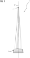
- a blade 1 can be seen in a perspective view.
- the blade 1 has a blade root 2 which is suitable for fastening in a rotor (not shown).
- the blade root 2 here has a so-called fir tree root shape.
- Such blades 1 can in turbomachines such. B. steam turbines, gas turbines or compressors are used.
- the blade 1 is along a radial direction 3 and has a blade tip 4 and a blade profile with a pressure side 5 and a suction side 6 .
- the blade 1 has blade cross-sectional profiles of different design along the radial direction 3 .
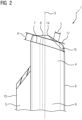
- the figure 2 shows the blade tip 4 of the blade 1 in an enlarged representation.
- the blade tip 4 has a blade tip surface 7 which, during operation, is opposite an inner wall of the housing (not shown).
- the blade tip surface 7 is inclined at an angle with respect to the radial direction 3, the blade tip surface 7 thereby being formed essentially parallel to the housing inner wall.
- An abradable layer 8 is arranged on the blade tip surface 7 .
- the abradable layer 8 is applied to the blade tip surface 7 essentially to further improve the gap losses.
- the abradable layer 8 is designed as an abrasive wearing layer, in which the risk of damage is minimized in the event of contact with the inner housing.
- the abradable layer 8 is thus designed in such a way that, during operation, the abradable layer 8 is eroded when it comes into contact with the inner wall of the housing.
- the abradable layer 8 is made of a lubricant.
- the lubricant includes graphite and/or hexagonal boron nitride.
- the abradable layer 8 is made porous. This means that a comparatively large number of small cavities are formed in the abradable layer 8 .
- the cavities that create porosity in the abradable layer 8 are made as described below.
- a method for producing the abradable layer 8 on a blade surface 7 is carried out.
- the abradable layer 8 is applied to the blade tip surface 7 by means of a thermal spray coating process such as APS or HVOF, the abradable layer 8 being provided with a lubricant such as graphite and/or hexagonal boron nitride.
- a polymer is added to the abradable layer 8 to produce the porous structure of the abradable layer 8 .
- a first heat treatment is carried out, during which the blade 1 is hardened.
- the abradable layer 8 is applied, and after the abradable layer 8 has been applied, a second heat treatment is carried out at a temperature at which the blade 1 is stress-relieved.
- the temperature is selected in such a way that the polymer in the abradable layer 8 sprayed on melts. This creates small cavities in the abradable layer 8 which ultimately lead to a porous structure of the abradable layer 8 .
- the blade 1 can be made of steel, titanium or composite materials.
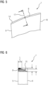
- the figure 4 shows a view of the blade tip 4 in the direction of the leading edge 9.
- the blade cross-sectional profile of the blade 1 can be described with a skeleton line, which is common practice in the construction of turbomachines.
- the abradable layer 8 is thereby along the arranged skeleton line. In a first embodiment, the abradable layer 8 therefore covers the entire blade tip surface 7.
- the blade 1 also has a leading edge 9 and a trailing edge 10, the abradable layer 8 being arranged from the leading edge 9 to the trailing edge 10 in the first embodiment.
- the entire blade 1 does not have to be formed with the abradable layer 8, but only an area in front of the trailing edge 10.
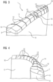
- the abradable 8 has an abradable surface 11, with the abradable surface 11 having notches 12 thereon.
- the notches 12 are applied to the abradable layer surface 11 in such a way that, during operation, a bursting away of the abradable layer 8 only results in a segment 13 arranged between two notches 12 bursting away.
- the notches 12 can thus be regarded as predetermined breaking points at the locations of which the abradable layer 8 is intended to break in the event that operating conditions occur which result in the abradable layer 8 being subjected to material-removing conditions.
- the notches 12 are formed substantially perpendicularly to the skeleton line, which reduces the manufacturing effort. Furthermore, the notches 12 are arranged at equidistant intervals along the mean line.
- the notches 12 are produced during the coating process or after the coating process using a machining process such as milling.
- the abradable layer 8 is formed continuously from the pressure side 5 to the suction side 6 .
- the abradable layer 8 is formed in such a way that rubbing against an inner wall of the housing during operation leads to the abrasion of the abradable layer 8, with the result that a contact surface (not shown) is created by abrasion, the contact surface being further driven in the radial direction 3 towards the blade root 2 becomes wider.
- the abradable layer 8 is formed on the blade tip surface 7 in such a way that the abradable layer 8, seen in cross section, represents a tip 14 at an obtuse angle.
- the abradable layer 8 is provided with an abrasion indicator 15 .
- the abradable layer 8 has a slit 16 which is arranged in such a way that a removal of the abradable layer 8 leads to a measurable length L of the slit and via the length L a height of the abradable layer 8 can be determined.
- the slot 16 is introduced from the edge on the pressure side 5 to the tip 14, which is shown in FIG figure 3 is shown.
- FIG figure 2 A side view of the abrasion indicator 15 can be seen.
- the abradable layer 8 can be removed, so that the contact surface in the figure 2 is shown with a line 17, is getting wider.
- This dash is 17 arranged essentially parallel to the blade tip surface 7 .
- a measurable slit 16 of length L is visible.
- a height H of the abradable layer 8 can thus be determined by simple trigonometric geometry considerations. It is therefore possible, so to speak, to deduce the state of the abradable layer 8 merely by looking at the length L of the slot 16 .
- the curved blade tips 4 are preferably used in low-pressure final stage blades in low-pressure steam turbines.
- the peripheral speed of the blade tip 4 can be at values greater than Mach 1. This enables use in the aerodynamic range of subsonic, transonic and supersonic flows.
- a blade 1 can be varied within a row of blades in a turbomachine.
- the blade 1 is used in a wet steam flow.
- the invention can be combined with a non-contact blade vibration measurement system since the distance between the blade tip 4 and the sensor can be minimized by the abradable layer 8 .
Landscapes
- Engineering & Computer Science (AREA)
- Mechanical Engineering (AREA)
- General Engineering & Computer Science (AREA)
- Turbine Rotor Nozzle Sealing (AREA)
- Structures Of Non-Positive Displacement Pumps (AREA)
Priority Applications (7)
| Application Number | Priority Date | Filing Date | Title |
|---|---|---|---|
| EP21203824.4A EP4170132A1 (fr) | 2021-10-20 | 2021-10-20 | Pale pour une turbomachine, ainsi que procédé de fabrication d'une pale, la pale comprenant un sommet avec un revêtement abradable |
| CN202280070605.0A CN118140037A (zh) | 2021-10-20 | 2022-09-09 | 用于流体机械的叶片以及用于制造叶片的方法,其中叶片具有带有在刮擦层表面上的切口的叶片尖端 |
| PCT/EP2022/075072 WO2023066566A1 (fr) | 2021-10-20 | 2022-09-09 | Pale à extrémité avec encoches dans une surface de revêtement abradable pour machine à débit continu et son procédé de fabrication |
| EP22777616.8A EP4388180B1 (fr) | 2021-10-20 | 2022-09-09 | Pale pour une turbomachine, ainsi que procédé de fabrication d'une pale, la pale comprenant un sommet avec des encoches sur la surface d'un revêtement abradable |
| US18/700,812 US20240426223A1 (en) | 2021-10-20 | 2022-09-09 | Blade for a continuous flow machine and method for producing a blade, wherein the blade has a blade tip with notches in an abradable coating surface |
| JP2024521149A JP7714794B2 (ja) | 2021-10-20 | 2022-09-09 | 摩耗性被膜表面にノッチ付きのブレードチップを備えた流体機械用ブレードとその製造方法 |
| KR1020247016429A KR20240090470A (ko) | 2021-10-20 | 2022-09-09 | 마모층 표면 상에 노치들을 갖는 블레이드 팁을 포함하는 블레이드로서의 유동 기계용 블레이드와, 블레이드 제조 방법 |
Applications Claiming Priority (1)
| Application Number | Priority Date | Filing Date | Title |
|---|---|---|---|
| EP21203824.4A EP4170132A1 (fr) | 2021-10-20 | 2021-10-20 | Pale pour une turbomachine, ainsi que procédé de fabrication d'une pale, la pale comprenant un sommet avec un revêtement abradable |
Publications (1)
| Publication Number | Publication Date |
|---|---|
| EP4170132A1 true EP4170132A1 (fr) | 2023-04-26 |
Family
ID=78332700
Family Applications (2)
| Application Number | Title | Priority Date | Filing Date |
|---|---|---|---|
| EP21203824.4A Withdrawn EP4170132A1 (fr) | 2021-10-20 | 2021-10-20 | Pale pour une turbomachine, ainsi que procédé de fabrication d'une pale, la pale comprenant un sommet avec un revêtement abradable |
| EP22777616.8A Active EP4388180B1 (fr) | 2021-10-20 | 2022-09-09 | Pale pour une turbomachine, ainsi que procédé de fabrication d'une pale, la pale comprenant un sommet avec des encoches sur la surface d'un revêtement abradable |
Family Applications After (1)
| Application Number | Title | Priority Date | Filing Date |
|---|---|---|---|
| EP22777616.8A Active EP4388180B1 (fr) | 2021-10-20 | 2022-09-09 | Pale pour une turbomachine, ainsi que procédé de fabrication d'une pale, la pale comprenant un sommet avec des encoches sur la surface d'un revêtement abradable |
Country Status (6)
| Country | Link |
|---|---|
| US (1) | US20240426223A1 (fr) |
| EP (2) | EP4170132A1 (fr) |
| JP (1) | JP7714794B2 (fr) |
| KR (1) | KR20240090470A (fr) |
| CN (1) | CN118140037A (fr) |
| WO (1) | WO2023066566A1 (fr) |
Citations (5)
| Publication number | Priority date | Publication date | Assignee | Title |
|---|---|---|---|---|
| US5434210A (en) * | 1990-11-19 | 1995-07-18 | Sulzer Plasma Technik, Inc. | Thermal spray powders for abradable coatings, abradable coatings containing solid lubricants and methods of fabricating abradable coatings |
| DE69826096T2 (de) * | 1997-11-26 | 2005-09-29 | United Technologies Corp. (N.D.Ges.D. Staates Delaware), Hartford | Schleifmittelbeschichtung aus stengelförmigem Zirkonoxid für eine Gasturbinendichtung |
| US9845685B2 (en) * | 2012-04-04 | 2017-12-19 | Mtu Aero Engines Gmbh | Process for producing a run-in coating |
| US20190309759A1 (en) * | 2016-11-18 | 2019-10-10 | Mitsubishi Heavy Industries, Ltd. | Compressor, and method for producing blade thereof |
| US20200277871A1 (en) * | 2018-07-12 | 2020-09-03 | Rolls-Royce North American Technologies, Inc. | Non-continuous abradable coatings |
Family Cites Families (5)
| Publication number | Priority date | Publication date | Assignee | Title |
|---|---|---|---|---|
| EP2309098A1 (fr) * | 2009-09-30 | 2011-04-13 | Siemens Aktiengesellschaft | Profil et aube directrice, aube rotorique, turbine à gaz et turbomachine associées |
| US8684669B2 (en) * | 2011-02-15 | 2014-04-01 | Siemens Energy, Inc. | Turbine tip clearance measurement |
| US9957834B2 (en) * | 2013-10-03 | 2018-05-01 | United Technologies Corporation | Rotor blade tip clearance |
| FR3026428B1 (fr) * | 2014-09-30 | 2019-10-25 | Safran Aircraft Engines | Aube de rotor de turbomachine a lechettes radiales |
| US10428674B2 (en) * | 2017-01-31 | 2019-10-01 | Rolls-Royce North American Technologies Inc. | Gas turbine engine features for tip clearance inspection |
-
2021
- 2021-10-20 EP EP21203824.4A patent/EP4170132A1/fr not_active Withdrawn
-
2022
- 2022-09-09 CN CN202280070605.0A patent/CN118140037A/zh active Pending
- 2022-09-09 EP EP22777616.8A patent/EP4388180B1/fr active Active
- 2022-09-09 US US18/700,812 patent/US20240426223A1/en active Pending
- 2022-09-09 KR KR1020247016429A patent/KR20240090470A/ko active Pending
- 2022-09-09 JP JP2024521149A patent/JP7714794B2/ja active Active
- 2022-09-09 WO PCT/EP2022/075072 patent/WO2023066566A1/fr not_active Ceased
Patent Citations (5)
| Publication number | Priority date | Publication date | Assignee | Title |
|---|---|---|---|---|
| US5434210A (en) * | 1990-11-19 | 1995-07-18 | Sulzer Plasma Technik, Inc. | Thermal spray powders for abradable coatings, abradable coatings containing solid lubricants and methods of fabricating abradable coatings |
| DE69826096T2 (de) * | 1997-11-26 | 2005-09-29 | United Technologies Corp. (N.D.Ges.D. Staates Delaware), Hartford | Schleifmittelbeschichtung aus stengelförmigem Zirkonoxid für eine Gasturbinendichtung |
| US9845685B2 (en) * | 2012-04-04 | 2017-12-19 | Mtu Aero Engines Gmbh | Process for producing a run-in coating |
| US20190309759A1 (en) * | 2016-11-18 | 2019-10-10 | Mitsubishi Heavy Industries, Ltd. | Compressor, and method for producing blade thereof |
| US20200277871A1 (en) * | 2018-07-12 | 2020-09-03 | Rolls-Royce North American Technologies, Inc. | Non-continuous abradable coatings |
Also Published As
| Publication number | Publication date |
|---|---|
| JP7714794B2 (ja) | 2025-07-29 |
| WO2023066566A1 (fr) | 2023-04-27 |
| JP2024538972A (ja) | 2024-10-28 |
| CN118140037A (zh) | 2024-06-04 |
| US20240426223A1 (en) | 2024-12-26 |
| EP4388180B1 (fr) | 2025-11-12 |
| KR20240090470A (ko) | 2024-06-21 |
| EP4388180A1 (fr) | 2024-06-26 |
Similar Documents
| Publication | Publication Date | Title |
|---|---|---|
| EP1953344B1 (fr) | Aube de turbine | |
| EP2647795B1 (fr) | Système d'étanchéité pour turbomachine | |
| DE69506890T2 (de) | Dynamische kontrolle vom schaufelspitzenspiel | |
| EP2372093B1 (fr) | Forme du joint d'étanchéité sur la plateforme d'une aube de turbine | |
| DE102012106175A1 (de) | Strukturierte schleifend abtragbare Beschichtungen für Oberflächen stationärer Dampfturbinenkomponenten | |
| EP3324002B1 (fr) | Système d'étanchéité pour une turbomachine et turbomachine axiale | |
| DE102014100241A1 (de) | Turbomaschine mit wirbelhemmender Dichtung | |
| EP2072757A1 (fr) | Bouclier anti-érosion pour aube rotative | |
| WO2005005784A1 (fr) | Aube de turbine | |
| EP2984294B1 (fr) | Aube de turbine avec arête de plate-forme étagée et biseauté | |
| CH701927B1 (de) | Statoranordnung, Kompressor und Gasturbinenmotor. | |
| EP2647796A1 (fr) | Système d'étanchéité pour turbomachine | |
| EP0976928B1 (fr) | Ensemble de pale pour turbomachine | |
| EP4388180B1 (fr) | Pale pour une turbomachine, ainsi que procédé de fabrication d'une pale, la pale comprenant un sommet avec des encoches sur la surface d'un revêtement abradable | |
| EP1315886A1 (fr) | Turbomachine dotee d'une aube | |
| DE102010048147B4 (de) | Schichtsystem zur Rotor-/Statordichtung einer Strömungsmaschine und Verfahren zum Herstellen eines derartigen Schichtsystems | |
| WO2006000174A1 (fr) | Revetement de retrecissement | |
| EP1008727A2 (fr) | Refroidissement de turbines à gaz | |
| EP3514333B1 (fr) | Carénage d'extrémité d'aube de rotor pour une turbomachine, aube de rotor, procédé de fabrication d'un carénage d'extrémité d'aube de rotor et aube de rotor | |
| EP1798376B1 (fr) | Méthode pour la fabrication d'un canal pour un flux secondaire | |
| DE102012001989B4 (de) | Verfahren zur mechanischen Randzonenverfestigung von Bauteilen | |
| DE102009053247A1 (de) | Verfahren zum Verändern einer Eigenfrequenz einer Schaufel für eine Strömungsmaschine | |
| EP4089264A1 (fr) | Agencement d'aubes pour turbines à gaz | |
| EP1711689B1 (fr) | Ensemble d' étanchéité | |
| DE102010050712A1 (de) | Bauelement einer Strömungsmaschine und Verfahren zum generativen Herstellen eines derartigen Bauelementes |
Legal Events
| Date | Code | Title | Description |
|---|---|---|---|
| PUAI | Public reference made under article 153(3) epc to a published international application that has entered the european phase |
Free format text: ORIGINAL CODE: 0009012 |
|
| STAA | Information on the status of an ep patent application or granted ep patent |
Free format text: STATUS: THE APPLICATION HAS BEEN PUBLISHED |
|
| AK | Designated contracting states |
Kind code of ref document: A1 Designated state(s): AL AT BE BG CH CY CZ DE DK EE ES FI FR GB GR HR HU IE IS IT LI LT LU LV MC MK MT NL NO PL PT RO RS SE SI SK SM TR |
|
| STAA | Information on the status of an ep patent application or granted ep patent |
Free format text: STATUS: THE APPLICATION IS DEEMED TO BE WITHDRAWN |
|
| 18D | Application deemed to be withdrawn |
Effective date: 20231027 |