EP4170154B1 - Disque atomiseur et procédé de fabrication d'un disque atomiseur - Google Patents
Disque atomiseur et procédé de fabrication d'un disque atomiseur Download PDFInfo
- Publication number
- EP4170154B1 EP4170154B1 EP21203995.2A EP21203995A EP4170154B1 EP 4170154 B1 EP4170154 B1 EP 4170154B1 EP 21203995 A EP21203995 A EP 21203995A EP 4170154 B1 EP4170154 B1 EP 4170154B1
- Authority
- EP
- European Patent Office
- Prior art keywords
- disc
- spray
- spray hole
- fluid
- guide
- Prior art date
- Legal status (The legal status is an assumption and is not a legal conclusion. Google has not performed a legal analysis and makes no representation as to the accuracy of the status listed.)
- Active
Links
Images

Classifications
-
- F—MECHANICAL ENGINEERING; LIGHTING; HEATING; WEAPONS; BLASTING
- F02—COMBUSTION ENGINES; HOT-GAS OR COMBUSTION-PRODUCT ENGINE PLANTS
- F02M—SUPPLYING COMBUSTION ENGINES IN GENERAL WITH COMBUSTIBLE MIXTURES OR CONSTITUENTS THEREOF
- F02M25/00—Engine-pertinent apparatus for adding non-fuel substances or small quantities of secondary fuel to combustion-air, main fuel or fuel-air mixture
- F02M25/022—Adding fuel and water emulsion, water or steam
- F02M25/0221—Details of the water supply system, e.g. pumps or arrangement of valves
- F02M25/0225—Water atomisers or mixers, e.g. using ultrasonic waves
-
- F—MECHANICAL ENGINEERING; LIGHTING; HEATING; WEAPONS; BLASTING
- F02—COMBUSTION ENGINES; HOT-GAS OR COMBUSTION-PRODUCT ENGINE PLANTS
- F02M—SUPPLYING COMBUSTION ENGINES IN GENERAL WITH COMBUSTIBLE MIXTURES OR CONSTITUENTS THEREOF
- F02M61/00—Fuel-injectors not provided for in groups F02M39/00 - F02M57/00 or F02M67/00
- F02M61/16—Details not provided for in, or of interest apart from, the apparatus of groups F02M61/02 - F02M61/14
- F02M61/162—Means to impart a whirling motion to fuel upstream or near discharging orifices
- F02M61/163—Means being injection-valves with helically or spirally shaped grooves
-
- F—MECHANICAL ENGINEERING; LIGHTING; HEATING; WEAPONS; BLASTING
- F02—COMBUSTION ENGINES; HOT-GAS OR COMBUSTION-PRODUCT ENGINE PLANTS
- F02M—SUPPLYING COMBUSTION ENGINES IN GENERAL WITH COMBUSTIBLE MIXTURES OR CONSTITUENTS THEREOF
- F02M61/00—Fuel-injectors not provided for in groups F02M39/00 - F02M57/00 or F02M67/00
- F02M61/16—Details not provided for in, or of interest apart from, the apparatus of groups F02M61/02 - F02M61/14
- F02M61/18—Injection nozzles, e.g. having valve seats; Details of valve member seated ends, not otherwise provided for
- F02M61/1806—Injection nozzles, e.g. having valve seats; Details of valve member seated ends, not otherwise provided for characterised by the arrangement of discharge orifices, e.g. orientation or size
- F02M61/1833—Discharge orifices having changing cross sections, e.g. being divergent
-
- F—MECHANICAL ENGINEERING; LIGHTING; HEATING; WEAPONS; BLASTING
- F02—COMBUSTION ENGINES; HOT-GAS OR COMBUSTION-PRODUCT ENGINE PLANTS
- F02M—SUPPLYING COMBUSTION ENGINES IN GENERAL WITH COMBUSTIBLE MIXTURES OR CONSTITUENTS THEREOF
- F02M61/00—Fuel-injectors not provided for in groups F02M39/00 - F02M57/00 or F02M67/00
- F02M61/16—Details not provided for in, or of interest apart from, the apparatus of groups F02M61/02 - F02M61/14
- F02M61/18—Injection nozzles, e.g. having valve seats; Details of valve member seated ends, not otherwise provided for
- F02M61/1853—Orifice plates
-
- F—MECHANICAL ENGINEERING; LIGHTING; HEATING; WEAPONS; BLASTING
- F01—MACHINES OR ENGINES IN GENERAL; ENGINE PLANTS IN GENERAL; STEAM ENGINES
- F01N—GAS-FLOW SILENCERS OR EXHAUST APPARATUS FOR MACHINES OR ENGINES IN GENERAL; GAS-FLOW SILENCERS OR EXHAUST APPARATUS FOR INTERNAL-COMBUSTION ENGINES
- F01N2610/00—Adding substances to exhaust gases
- F01N2610/02—Adding substances to exhaust gases the substance being ammonia or urea
-
- F—MECHANICAL ENGINEERING; LIGHTING; HEATING; WEAPONS; BLASTING
- F01—MACHINES OR ENGINES IN GENERAL; ENGINE PLANTS IN GENERAL; STEAM ENGINES
- F01N—GAS-FLOW SILENCERS OR EXHAUST APPARATUS FOR MACHINES OR ENGINES IN GENERAL; GAS-FLOW SILENCERS OR EXHAUST APPARATUS FOR INTERNAL-COMBUSTION ENGINES
- F01N2610/00—Adding substances to exhaust gases
- F01N2610/14—Arrangements for the supply of substances, e.g. conduits
-
- F—MECHANICAL ENGINEERING; LIGHTING; HEATING; WEAPONS; BLASTING
- F01—MACHINES OR ENGINES IN GENERAL; ENGINE PLANTS IN GENERAL; STEAM ENGINES
- F01N—GAS-FLOW SILENCERS OR EXHAUST APPARATUS FOR MACHINES OR ENGINES IN GENERAL; GAS-FLOW SILENCERS OR EXHAUST APPARATUS FOR INTERNAL-COMBUSTION ENGINES
- F01N2610/00—Adding substances to exhaust gases
- F01N2610/14—Arrangements for the supply of substances, e.g. conduits
- F01N2610/1453—Sprayers or atomisers; Arrangement thereof in the exhaust apparatus
-
- F—MECHANICAL ENGINEERING; LIGHTING; HEATING; WEAPONS; BLASTING
- F02—COMBUSTION ENGINES; HOT-GAS OR COMBUSTION-PRODUCT ENGINE PLANTS
- F02M—SUPPLYING COMBUSTION ENGINES IN GENERAL WITH COMBUSTIBLE MIXTURES OR CONSTITUENTS THEREOF
- F02M25/00—Engine-pertinent apparatus for adding non-fuel substances or small quantities of secondary fuel to combustion-air, main fuel or fuel-air mixture
- F02M25/022—Adding fuel and water emulsion, water or steam
- F02M25/025—Adding water
- F02M25/028—Adding water into the charge intakes
Definitions
- the present invention relates to an atomizer disc for atomizing a fluid, comprising at least one fluid guide disc and at least one spray hole disc arranged on the fluid guide disc, which has at least one spray hole offset from the center of the atomizer disc, and to a method for producing such an atomizer disc.
- Multi-part atomizer discs of the type mentioned are known, for example, from the European patent application EP 1 186 774 or the US Patent 5,899,390 known.
- Modern combustion engines require optimal atomization of fluids such as fuels to trigger the required reaction effects and thus increase their efficiency. Fluids are also atomized during charge air pretreatment, for example, water, which cools and humidifies the charge air.
- charge air pretreatment for example, water, which cools and humidifies the charge air.
- the fluid is often set in rotation by swirl geometries or collided head-on by means of intersecting channels before exiting at least one atomizer bore of an atomizer disc.
- Such channels are usually embossed into single- or multi-piece atomizer discs.
- a channel geometry is cut out in a fluid guide disc, with the channel base being formed by a disc adjacent to this disc.
- the desired cross-section is achieved by an anisotropic punching of the material and conically deformed contours. falsified.
- punching indentations are often accompanied by undesirable material changes and compressions, which impair the desired atomization of the fluid emerging from a spray hole.
- Such an atomizing disc is known, for example, from the German patent application DE 10 2015 225 338 A1 known.
- a fluid chamber is formed between two discs, from which the fluid emerges through, in particular, several spray hole bores.
- the invention is based on the object of providing an improved atomizer disc and an improved method for producing an atomizer disc.
- an atomizer disc for atomizing a fluid comprising at least one fluid guide disc and at least one spray hole disc arranged on the fluid guide disc, which has at least one spray hole offset from the center of the atomizer disc.
- a channel geometry is cut out in the fluid guide disc, forming the side surfaces of a guide channel for the fluid.
- the bottom surface of the guide channel is formed by the spray hole disc.
- the design with the cut-out channel geometry allows for a guide channel that exactly corresponds to the geometric design for the fluid to be
- the resulting increased accuracy allows the flow through at least one flow channel to be calculated more precisely.
- Another advantage of the proposed atomizer disc is that no undesirable turbulence occurs along punch indentations, thus maintaining the defined flow path of the fluid. Accordingly, the precisely manufacturable channel geometry allows the desired flow rate to be calculated and maintained more easily.
- the proposed atomizer disc is intended for atomizing one of these fluids, supplied in particular by means of an injection or metering valve.
- the fluid can be, in particular when the atomizer disc is used in an internal combustion engine, for example, for atomizing fuel, a fluid used for exhaust gas purification, such as urea, or water used for cooling and/or humidifying the charge air.
- the proposed atomizer disc is designed in at least two parts and has a separately manufactured fluid guide disc. The two-part design makes it possible to precisely cut out the intended channel geometry in the fluid guide disc.
- the channel geometry can be created using any suitable manufacturing and, in particular, cutting process, such as a punching process, or a laser or waterjet cutting process, which allows for the production of sufficiently precise cut edges.
- the cut edges of the cut-out channel geometry form the side surfaces of a guide channel for the fluid.
- the base surface of the guide channel is formed by the spray orifice plate arranged on the fluid guide plate. This enables flexible and precise production of the intended channel geometry of the atomizer plate. This reduces the influences on the fluid flow in the guide channels caused by the manufacturing of the atomizer plate.
- the spray hole disc has at least one spray hole, to which the fluid is guided through the guide channel and through which it then exits, particularly in atomized form, into the area surrounding the atomizer disc.
- a spray hole can, of course, have any other suitable contour besides a circular one. In particular, various channel systems with different spray hole arrangements can be easily and simply combined and analyzed for prototype construction.
- the fluid guide disc and the spray hole disc have the same thickness or are constructed with different thicknesses.
- the fluid guide disc and the spray hole disc can each have a thickness in the low single-digit micrometer range ( ⁇ m). Furthermore, the machining direction can be varied during production, which also contributes to improved efficiency.
- the fluid guide disc and the spray hole disc can also be made of the same or different materials.
- the guide channel is designed to guide the fluid to a spray hole with a substantially laminar flow.
- this increases the dynamic pressure in the fluid in the area of the spray hole.
- This design supports effective atomization of the fluid as it flows through the spray hole through a suitable supply of the fluid.
- An increased dynamic pressure at the end of the guide channel can accelerate the fluid as it flows through the spray hole.
- a particularly laminar swirl flow with corresponding acceleration of the fluid can be created through suitable guidance of a laminar fluid.
- the guide channel has a recess formed in the disc in the region of at least one spray hole.
- a recess is typically used to create a desired fluid flow. Depending on the design of the recess, it can serve, for example, to create a swirling flow in the fluid.
- the recess formed in the disc can be embossed or manufactured therein or cut out of it using a machining process.
- the spray hole disc is formed in at least two parts in the direction of passage of the at least one spray hole, wherein the inner spray hole disc, which faces the fluid guide disc, has at least one recess.
- An at least two-part construction of the spray hole disc enables a more flexible design of the recess, in particular with regard to its geometry, arrangement, and manufacture.
- the elements of the spray hole disc can be made of the same or different materials.
- the spray hole disc has multiple spray holes, with the channel geometry being designed to guide fluid to each spray hole via a respective guide channel.
- the flow of fluid to each spray hole can be individually configured.
- the atomizer disc if there are several spray holes, these are arranged circularly around the center of the channel geometry. Such an arrangement allows for individual and, in particular, equal guidance of the fluid to each of the spray holes.
- several spray holes can be evenly distributed on a circle arranged around the center of the channel geometry, or in a predetermined Arrangement, for example, depending on the geometry and/or flow conditions in the space into which the fluid is introduced, particularly in atomized form.
- the number and respective diameter and/or opening geometry of the spray holes can be selected, particularly depending on the intended volume flow and the atomization properties of the fluid.
- the at least one spray hole is oriented at an oblique angle or at a right angle to the bottom surface of the guide channel.
- the alignment of the at least one spray hole to the bottom surface of the guide channel can be provided in particular depending on the geometry and/or the flow conditions in the space into which the fluid is introduced, in particular in atomized form, and/or depending on the interaction with the flow formation in the feed channel and/or depending on the atomization properties resulting from the spray hole geometry of the spray hole geometry, in particular associated therewith.
- the at least one spray hole can be cylindrical or conically tapering or widening, or can also have a cross-section that changes along the direction of passage of the fluid.
- the fluid guide disc and the spray hole disc are firmly connected to each other. This allows the atomizer disc to be handled as a whole, similar to a one-piece atomizer disc.
- the atomizer disc is provided with at least one connecting element arranged on the circumference of the atomizer disc, which serves to connect the atomizer disc to a fluid valve.
- the one or more connecting elements are designed such that a particularly positive connection to a fluid valve can be established by means of them.
- the atomizer disc produced using the proposed method has at least one or more advantages and properties of the previously described atomizer disc. Consequently, the advantages and properties described above apply analogously to a correspondingly designed atomizer disc produced using the proposed manufacturing method, and conversely, the advantages and properties described below, which result from the manufacturing method, also apply to the atomizer disc produced using this method.
- the proposed manufacturing process prevents anisotropic punching indentations, particularly on the walls of the guide channel in the fluid guide disc, by cutting out the channel geometry.
- a guide channel for the fluid to be atomized can be produced that precisely corresponds to the geometric design.
- the resulting increased accuracy allows the flow through the at least one flow channel to be calculated more precisely.
- a further advantage of the proposed manufacturing method is that no unwanted turbulence occurs along the punch indentations, thus maintaining the defined flow path of the fluid. Accordingly, the precisely manufactured channel geometry allows the desired fluid flow to be achieved.
- the proposed manufacturing process for the atomizer disc provides for an atomizer disc constructed in at least two parts. This allows the intended channel geometry to be precisely cut out in the fluid guide disc, resulting in precisely aligned cut edges. This largely eliminates the influences on fluid flow in the guide channels caused by the manufacturing of the atomizer disc.
- a first step a) the fluid guide disc is cut out with a channel geometry and a peripheral geometry arranged therein.
- Any suitable cutting process can be used for this purpose, such as a punching process, a laser cutting process, or a waterjet cutting process.
- the spray hole disc is cut out with at least one spray hole arranged therein and a peripheral geometry.
- Any suitable cutting method can be used for this purpose, such as a punching process, a laser cutting process, or a waterjet cutting process.
- the spray holes can also be produced using a micro-punching process, for example.
- the fluid guide disc is arranged on the spray hole disc in such a way that the spray hole disc covers the bottom surface of the forms at least one guide channel for the fluid; and in step d), the fluid guide disc is joined to the spray hole disc to form the atomizer disc.
- the fluid guide disc and the spray hole disc can be firmly connected to one another, in particular by establishing a positive and/or non-positive and/or material connection between the discs.
- An embodiment of the method for producing an atomizer disk in which the spray hole disk is formed in two parts in the direction of passage of the at least one spray hole, has as a further step step b1), in which an inner spray hole disk with a circumferential geometry and with at least one recess is cut out at the position of the at least one spray hole. Cutting out the recess in an inner spray hole disk provided for this purpose also enables the production of a very precise contour of the recess. Because the recess has a greater extent than the spray hole arranged in an outer spray hole disk, the recess forms a recess of the guide channel after the atomizer disk is joined.
- An associated flow change occurs depending on the geometry of the recess, in particular in cooperation with the geometry of the guide channel formed in the fluid guide disk.
- an at least partially rounded recess can cause the formation of a swirling flow in the fluid, in particular to achieve a desired atomization of the fluid after it exits the atomizer disk.
- a depression is embossed into the spray hole disk in at least one area surrounding the spray hole.
- Such an embossed depression of the guide channel can also be used, in particular, to influence the fluid flow before passing through through a spray hole in order to achieve the desired atomization of the fluid.
- At least one joining element is formed on the circumference of the fluid guide disk and/or on the circumference of the spray hole disk, in particular in steps a) and/or b).
- At least one joining element is formed on the circumference of the fluid guide disc, which is intended for joining the fluid guide disc to the spray orifice disc.
- at least one joining element can also be formed on the circumference of the spray orifice disc, which is intended for joining the spray orifice disc to the fluid guide disc.
- Such joining elements are designed in particular to produce a joining connection, for example by engaging with the circumferential contour of the other disc, as can be provided in particular with clamps or the like.
- one or more such joining elements can engage with one or more joining elements arranged on the respective other disc element of the atomizer disc.
- a particularly positive and/or non-positive connection can be formed between the spray orifice disc and the fluid guide disc by means of the joining elements on the circumference of the fluid guide disc and/or the spray orifice disc.
- a joining element arranged on the spray hole disk is designed as a tab with a recess
- a joining element arranged on the fluid guide disk is designed as a tab that can be arranged in the recess of the tab on the spray hole disk.
- the fluid guide disk is arranged on the spray orifice disk and the at least one joining element arranged on the fluid guide disk and/or the at least one joining element arranged on the spray orifice disk is/are deformed, in particular caulked, thereby establishing a connection between the fluid guide disk and the spray orifice disk.
- the at least one joining element By deforming the at least one joining element, the fluid guide disk and the spray orifice disk are firmly connected to one another. In particular, a positive and/or non-positive connection is established in this way between the elements of the atomizer disk.
- the joining element can be designed such that it forms a connecting element for connecting the atomizer disk to a fluid valve.
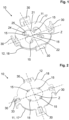
- Fig. 1 shows a three-dimensional view of an exemplary atomizer disk 10 according to the invention in a view of the fluid guide disk 11.
- the atomizer disk 10 has a spray hole disk 12, which in Fig. 1 is arranged below the fluid guide disk 11 and has four spray holes 15 offset from the center Z of the atomizer disk 12.
- a channel geometry 21 is cut out in the fluid guide disk 11, which forms the side surfaces 22 of a guide channel 25 for the fluid, and the bottom surface 24 of the guide channel 25 is formed by the spray hole disk 12.
- Each guide channel 25 of the exemplary atomizer disk 10 is designed to guide the fluid with a substantially laminar flow to a spray hole 15 and is further designed such that the back pressure in the fluid increases in the region of the spray hole 15.
- the fluid guide disk 11 has a circumferential geometry 17 and the spray hole disk 12 has a circumferential geometry 18, which in the exemplary embodiment are also produced by a cutting process.
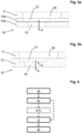
- Fig. 3b shows a sectional view of a detail of another exemplary atomizer disk 10 according to the invention, the spray hole disk 12 of which is formed as a single piece in the direction of passage of the at least one spray hole 15.
- the single-piece spray hole disk 12 has a recess 27 in the direction of passage D of a spray hole 15, which widens the guide channel 25 in the region of the spray hole 15.
- the spray hole 15 at the in Fig. 3b shown version is aligned at an oblique angle to the bottom surface 24 of the guide channel 25.
- Fig. 4 shows a schematic representation of a flow diagram of the method according to the invention for producing an atomizer disk 10 for atomizing a fluid with at least one fluid guide disk 11 in which a channel geometry 21 is formed and at least one spray hole disk 12 arranged on the fluid guide disk 11, which has at least one spray hole 15.
- Fig. 5 shows a further three-dimensional view of the exemplary atomizer disk 10 according to the invention from Fig. 1 after arranging the fluid guide disc 11 on the spray hole disc 12.
- Four joining elements 31, 32 are formed on both the circumference 17 of the fluid guide disc 11 and the circumference 18 of the spray hole disc 12, which are provided with an upward bend for joining the fluid guide disc 11 and the spray hole disc 12.
- the joining elements 32 arranged on the spray hole disc 12 are designed as a tab with a recess 33 (cf. Fig. 6 ) and the joining elements 31 arranged on the fluid guide disc 11 as a tab, which in Fig. 5 is arranged in the recess 33 of the joining element 32 on the spray hole disc 12.
Landscapes
- Engineering & Computer Science (AREA)
- Chemical & Material Sciences (AREA)
- Combustion & Propulsion (AREA)
- Mechanical Engineering (AREA)
- General Engineering & Computer Science (AREA)
- Health & Medical Sciences (AREA)
- Public Health (AREA)
- Water Supply & Treatment (AREA)
- Nozzles (AREA)
Claims (14)
- Disque d'atomisation pour atomiser un fluide, comprenant au moins un disque de guidage de fluide (11) et au moins un disque à trou de projection (12) disposé sur le disque de guidage de fluide (11), lequel présente au moins un trou de projection (15) décalé par rapport au centre (Z) du disque d'atomisation (10), une géométrie formant canal (21) étant découpée dans le disque de guidage de fluide (11), laquelle forme les surfaces latérales (22) d'un canal de guidage (25) pour le fluide, et la surface de fond (24) du canal de guidage (25) étant formée par le disque à trou de protection (12),
caractérisé par au moins un élément de liaison (30) disposé à la périphérie (17, 18) du disque d'atomisation (10), qui est prévu pour relier le disque d'atomisation (10) à une soupape de fluide. - Disque d'atomisation selon la revendication 1,
caractérisé en ce que le canal de guidage (25) est conçu pour guider le fluide avec un écoulement sensiblement laminaire vers un trou de projection (15). - Disque d'atomisation selon l'une au moins des revendications précédentes,
caractérisé en ce que le canal de guidage (25) présente, dans la zone d'au moins un perçage de projection, un renfoncement (27) qui est formé dans le disque à trou de projection (12). - Disque d'atomisation selon la revendication 3,
caractérisé en ce que le disque à trou de projection (12) est réalisé en deux parties dans la direction de passage dudit au moins un trou de projection (15), le disque à trou de projection intérieur (12a) tourné vers le disque de guidage de fluide (11) présentant ledit au moins un renfoncement (27). - Disque d'atomisation selon l'une au moins des revendications précédentes,
caractérisé en ce que le disque à trous de projection (12) présente plusieurs trous de projection (15), et la géométrie formant canal (21) est conçue pour guider le fluide vers un trou de projection (15) respectif au moyen d'un canal de guidage (25) respectif. - Disque d'atomisation selon l'une au moins des revendications précédentes,
caractérisé en ce que, dans le cas de plusieurs trous de projection (15), ceux-ci sont disposés de manière circulaire autour du centre de la géométrie formant canal (21). - Disque d'atomisation selon l'une au moins des revendications précédentes,
caractérisé en ce que ledit au moins un trou de projection (15) est orienté selon un angle en oblique ou un angle droit par rapport à la surface de fond (24) du canal de guidage (25). - Disque d'atomisation selon l'une au moins des revendications précédentes,
caractérisé en ce que le disque de guidage de fluide (11) et le disque à trous de projection (12) sont solidaires l'un de l'autre. - Procédé de fabrication d'un disque d'atomisation (10) pour atomiser un fluide, comprenant au moins un disque de guidage de fluide (11) dans lequel est formée une géométrie formant canal (21), et au moins un disque à trou de projection (12) disposé sur le disque de guidage de fluide (11) et présentant au moins un trou de projection (15), comprenant les étapes consistant à :a) découper un disque de guidage de fluide (11) présentant une géométrie formant canal (21), disposée dans celui-ci, et une géométrie périphérique (17) ;b) découper un disque à trou de projection (12) présentant au moins un trou de projection (15), disposé dans celui-ci, et une géométrie périphérique (18), au moins un élément de liaison (30) disposé à la périphérie (17, 18) du disque d'atomisation (10) étant prévu pour relier le disque d'atomisation (10) à une soupape de fluide,c) placer le disque de guidage de fluide (11) sur le disque à trou de projection (12) de telle sorte que le disque à trou de projection (12) forme la surface de fond (24) dudit au moins un canal de guidage (25) pour le fluide; etd) assembler le disque de guidage de fluide (11) avec le disque à trou de projection (12) pour former le disque d'atomisation (10).
- Procédé de fabrication d'un disque d'atomisation (10) selon la revendication 9,
dans lequel le disque à trou de projection (11) est réalisé en deux parties dans la direction de passage dudit au moins un trou de projection (15), caractérisé par l'étape supplémentaire consistant à:
b1) découper un disque à trou de projection intérieur (12a) ayant une géométrie périphérique et présentant au moins un évidement à l'emplacement dudit au moins un trou de projection (15), qui a une extension plus grande que le trou de projection (15) disposé dans un disque à trou de projection extérieur (12b). - Procédé de fabrication d'un disque d'atomisation (10) selon l'une des revendications 9 ou 10,
caractérisé en ce qu'à l'étape b) ou à l'étape b1), un renfoncement (27) est estampé dans le disque à trou de projection (12) dans au moins une zone entourant le trou de projection (15). - Procédé de fabrication d'un disque d'atomisation (10) selon l'une des revendications 9 à 11,
caractérisé en ce qu'au moins un élément d'assemblage (31, 32) est réalisé à la périphérie (17) du disque de guidage de fluide (11) et/ou à la périphérie (18) du disque à trou de projection (12). - Procédé de fabrication d'un disque d'atomisation (10) selon la revendication 12,
caractérisé en ce que ledit au moins un élément d'assemblage (32) disposé sur le disque à trou de projection (12) est réalisé sous la forme d'une patte ayant un évidement (33), et ledit au moins un élément d'assemblage (31) disposé sur le disque de guidage de fluide (11) est réalisé sous la forme d'une patte qui peut être disposée dans l'évidement (33) de la patte située sur le disque à trou de projection (12). - Procédé de fabrication d'un disque d'atomisation (10) selon l'une des revendications 9 à 13,caractérisé en ce que, à l'étape d), le disque de guidage de fluide (11) est disposé sur le disque à trou de projection (12), eten ce que ledit au moins un élément d'assemblage (32) disposé sur le disque de guidage de fluide (11) et/ou ledit au moins un élément d'assemblage (32) disposé sur le disque à trou de projection (12) est/sont déformé(s), ce qui permet d'établir une liaison entre le disque de guidage de fluide (11) et le disque à trou de projection (12).
Priority Applications (2)
| Application Number | Priority Date | Filing Date | Title |
|---|---|---|---|
| EP21203995.2A EP4170154B1 (fr) | 2021-10-21 | 2021-10-21 | Disque atomiseur et procédé de fabrication d'un disque atomiseur |
| PCT/EP2022/055440 WO2023066530A1 (fr) | 2021-10-21 | 2022-03-03 | Disque d'atomisation et procédé de production de disque d'atomisation |
Applications Claiming Priority (1)
| Application Number | Priority Date | Filing Date | Title |
|---|---|---|---|
| EP21203995.2A EP4170154B1 (fr) | 2021-10-21 | 2021-10-21 | Disque atomiseur et procédé de fabrication d'un disque atomiseur |
Publications (2)
| Publication Number | Publication Date |
|---|---|
| EP4170154A1 EP4170154A1 (fr) | 2023-04-26 |
| EP4170154B1 true EP4170154B1 (fr) | 2025-06-25 |
Family
ID=78371852
Family Applications (1)
| Application Number | Title | Priority Date | Filing Date |
|---|---|---|---|
| EP21203995.2A Active EP4170154B1 (fr) | 2021-10-21 | 2021-10-21 | Disque atomiseur et procédé de fabrication d'un disque atomiseur |
Country Status (2)
| Country | Link |
|---|---|
| EP (1) | EP4170154B1 (fr) |
| WO (1) | WO2023066530A1 (fr) |
Family Cites Families (6)
| Publication number | Priority date | Publication date | Assignee | Title |
|---|---|---|---|---|
| BR9605943A (pt) * | 1995-03-29 | 1997-08-19 | Bosch Gmbh Robert | Disco perfurado particularmente para válvulas de injeção |
| US6405945B1 (en) * | 2000-09-06 | 2002-06-18 | Visteon Global Tech., Inc. | Nozzle for a fuel injector |
| DE102004049280A1 (de) * | 2004-10-09 | 2006-04-13 | Robert Bosch Gmbh | Brennstoffeinspritzventil |
| US10047713B2 (en) * | 2013-11-11 | 2018-08-14 | Enplas Corporation | Attachment structure of fuel injection device nozzle plate |
| KR101853464B1 (ko) * | 2015-06-22 | 2018-06-04 | 두산중공업 주식회사 | 실링구조를 포함하는 연료공급노즐. |
| DE102015225338A1 (de) | 2015-12-15 | 2017-07-06 | Robert Bosch Gmbh | Spritzlochscheibe und Ventil |
-
2021
- 2021-10-21 EP EP21203995.2A patent/EP4170154B1/fr active Active
-
2022
- 2022-03-03 WO PCT/EP2022/055440 patent/WO2023066530A1/fr not_active Ceased
Also Published As
| Publication number | Publication date |
|---|---|
| EP4170154A1 (fr) | 2023-04-26 |
| WO2023066530A1 (fr) | 2023-04-27 |
Similar Documents
| Publication | Publication Date | Title |
|---|---|---|
| EP0720691B1 (fr) | Pointeau pour soupape a actionnement electromagnetique et son procede de production | |
| DE69509889T2 (de) | Kraftstoffeinspritzventil mit mehrfachen lochscheibenelementen | |
| EP0862690B1 (fr) | Disque perfore et soupape munie d'un disque perfore | |
| EP1355061B1 (fr) | Soupape d'injection, en particulier soupape d'injection de carburant | |
| DE69203197T2 (de) | Elektromagnetisch betätigbares Kraftstoffzerstäubungs- und Dosierventil für eine Kraftstoffansaugvorrichtung einer Brennkraftmaschine. | |
| EP0920359B1 (fr) | Soupape et procede de realisation d'un siege destine a une soupape | |
| EP0717816B1 (fr) | Soupape a commande electromagnetique | |
| DE10201272A1 (de) | Zur Verwendung mit Fluidinjektoren geeignete Düsen | |
| DE19703200A1 (de) | Brennstoffeinspritzventil | |
| EP0310819A1 (fr) | Soupape à injection de combustible | |
| WO1999053193A1 (fr) | Disque diffuseur et soupape d'injection de carburant equipee de ce dernier | |
| EP1049871A1 (fr) | Soupape d'injection de carburant | |
| DE112004000897B4 (de) | Kraftstoffeinspritzventil mit einer Düsenscheibe und Verfahren zum Herstellen der Düsenscheibe mit einem asymmetrischen Dorn | |
| DE19736684A1 (de) | Brennstoffeinspritzventil | |
| DE19757117A1 (de) | Verfahren zur Herstellung eines Ventilsitzkörpers für ein Brennstoffeinspritzventil und Brennstoffeinspritzventil | |
| DE19954102B4 (de) | Kraftstoffinjektor | |
| DE19636396A1 (de) | Brennstoffeinspritzventil | |
| DE602004008292T2 (de) | Kraftstoffeinspritzventil mit einer lochscheibe und verfahren zur herstellung der lochscheibe durch ausschaben und stanzen | |
| EP0939858B1 (fr) | Disque perfore ou disque de pulverisation et soupape injectrice dotee d'un tel disque perfore ou disque de pulverisation | |
| DE19913317B4 (de) | Verfahren zur Herstellung einer Düsenplatte mit einem Düsenloch, sowie Brennstoffeinspritzvorrichtung | |
| DE19927196A1 (de) | Brennstoffeinspritzventil | |
| EP1402175A1 (fr) | Soupape d'injection de carburant | |
| EP1337752A2 (fr) | Soupape d'injection de carburant et procede de production d'aiguilles de soupape ou de corps de fermeture de soupape pour soupapes d'injection de carburant | |
| EP4170154B1 (fr) | Disque atomiseur et procédé de fabrication d'un disque atomiseur | |
| EP1327066B1 (fr) | Soupape d'injection de carburant |
Legal Events
| Date | Code | Title | Description |
|---|---|---|---|
| PUAI | Public reference made under article 153(3) epc to a published international application that has entered the european phase |
Free format text: ORIGINAL CODE: 0009012 |
|
| STAA | Information on the status of an ep patent application or granted ep patent |
Free format text: STATUS: THE APPLICATION HAS BEEN PUBLISHED |
|
| AK | Designated contracting states |
Kind code of ref document: A1 Designated state(s): AL AT BE BG CH CY CZ DE DK EE ES FI FR GB GR HR HU IE IS IT LI LT LU LV MC MK MT NL NO PL PT RO RS SE SI SK SM TR |
|
| STAA | Information on the status of an ep patent application or granted ep patent |
Free format text: STATUS: REQUEST FOR EXAMINATION WAS MADE |
|
| 17P | Request for examination filed |
Effective date: 20231026 |
|
| RBV | Designated contracting states (corrected) |
Designated state(s): AL AT BE BG CH CY CZ DE DK EE ES FI FR GB GR HR HU IE IS IT LI LT LU LV MC MK MT NL NO PL PT RO RS SE SI SK SM TR |
|
| RAP1 | Party data changed (applicant data changed or rights of an application transferred) |
Owner name: HEINZ HAENGGI SWISS STAMPING SOLUTIONS GMBH |
|
| GRAP | Despatch of communication of intention to grant a patent |
Free format text: ORIGINAL CODE: EPIDOSNIGR1 |
|
| STAA | Information on the status of an ep patent application or granted ep patent |
Free format text: STATUS: GRANT OF PATENT IS INTENDED |
|
| RIC1 | Information provided on ipc code assigned before grant |
Ipc: F02M 25/028 20060101ALN20250107BHEP Ipc: F01N 3/029 20060101ALN20250107BHEP Ipc: F02M 61/18 20060101ALI20250107BHEP Ipc: F02M 61/16 20060101ALI20250107BHEP Ipc: F02M 25/022 20060101AFI20250107BHEP |
|
| INTG | Intention to grant announced |
Effective date: 20250127 |
|
| GRAS | Grant fee paid |
Free format text: ORIGINAL CODE: EPIDOSNIGR3 |
|
| GRAA | (expected) grant |
Free format text: ORIGINAL CODE: 0009210 |
|
| STAA | Information on the status of an ep patent application or granted ep patent |
Free format text: STATUS: THE PATENT HAS BEEN GRANTED |
|
| AK | Designated contracting states |
Kind code of ref document: B1 Designated state(s): AL AT BE BG CH CY CZ DE DK EE ES FI FR GB GR HR HU IE IS IT LI LT LU LV MC MK MT NL NO PL PT RO RS SE SI SK SM TR |
|
| REG | Reference to a national code |
Ref country code: GB Ref legal event code: FG4D Free format text: NOT ENGLISH |
|
| REG | Reference to a national code |
Ref country code: CH Ref legal event code: EP |
|
| REG | Reference to a national code |
Ref country code: CH Ref legal event code: EP |
|
| REG | Reference to a national code |
Ref country code: IE Ref legal event code: FG4D Free format text: LANGUAGE OF EP DOCUMENT: GERMAN |
|
| REG | Reference to a national code |
Ref country code: DE Ref legal event code: R096 Ref document number: 502021007829 Country of ref document: DE |
|
| PG25 | Lapsed in a contracting state [announced via postgrant information from national office to epo] |
Ref country code: FI Free format text: LAPSE BECAUSE OF FAILURE TO SUBMIT A TRANSLATION OF THE DESCRIPTION OR TO PAY THE FEE WITHIN THE PRESCRIBED TIME-LIMIT Effective date: 20250625 |
|
| REG | Reference to a national code |
Ref country code: LT Ref legal event code: MG9D |
|
| PG25 | Lapsed in a contracting state [announced via postgrant information from national office to epo] |
Ref country code: NO Free format text: LAPSE BECAUSE OF FAILURE TO SUBMIT A TRANSLATION OF THE DESCRIPTION OR TO PAY THE FEE WITHIN THE PRESCRIBED TIME-LIMIT Effective date: 20250925 Ref country code: GR Free format text: LAPSE BECAUSE OF FAILURE TO SUBMIT A TRANSLATION OF THE DESCRIPTION OR TO PAY THE FEE WITHIN THE PRESCRIBED TIME-LIMIT Effective date: 20250926 |
|
| PG25 | Lapsed in a contracting state [announced via postgrant information from national office to epo] |
Ref country code: BG Free format text: LAPSE BECAUSE OF FAILURE TO SUBMIT A TRANSLATION OF THE DESCRIPTION OR TO PAY THE FEE WITHIN THE PRESCRIBED TIME-LIMIT Effective date: 20250625 |
|
| PG25 | Lapsed in a contracting state [announced via postgrant information from national office to epo] |
Ref country code: HR Free format text: LAPSE BECAUSE OF FAILURE TO SUBMIT A TRANSLATION OF THE DESCRIPTION OR TO PAY THE FEE WITHIN THE PRESCRIBED TIME-LIMIT Effective date: 20250625 |
|
| PG25 | Lapsed in a contracting state [announced via postgrant information from national office to epo] |
Ref country code: RS Free format text: LAPSE BECAUSE OF FAILURE TO SUBMIT A TRANSLATION OF THE DESCRIPTION OR TO PAY THE FEE WITHIN THE PRESCRIBED TIME-LIMIT Effective date: 20250925 |
|
| PG25 | Lapsed in a contracting state [announced via postgrant information from national office to epo] |
Ref country code: LV Free format text: LAPSE BECAUSE OF FAILURE TO SUBMIT A TRANSLATION OF THE DESCRIPTION OR TO PAY THE FEE WITHIN THE PRESCRIBED TIME-LIMIT Effective date: 20250625 |
|
| REG | Reference to a national code |
Ref country code: NL Ref legal event code: MP Effective date: 20250625 |
|
| REG | Reference to a national code |
Ref country code: CH Ref legal event code: U11 Free format text: ST27 STATUS EVENT CODE: U-0-0-U10-U11 (AS PROVIDED BY THE NATIONAL OFFICE) Effective date: 20251101 |
|
| PG25 | Lapsed in a contracting state [announced via postgrant information from national office to epo] |
Ref country code: NL Free format text: LAPSE BECAUSE OF FAILURE TO SUBMIT A TRANSLATION OF THE DESCRIPTION OR TO PAY THE FEE WITHIN THE PRESCRIBED TIME-LIMIT Effective date: 20250625 |
|
| PG25 | Lapsed in a contracting state [announced via postgrant information from national office to epo] |
Ref country code: PT Free format text: LAPSE BECAUSE OF FAILURE TO SUBMIT A TRANSLATION OF THE DESCRIPTION OR TO PAY THE FEE WITHIN THE PRESCRIBED TIME-LIMIT Effective date: 20251027 |
|
| PG25 | Lapsed in a contracting state [announced via postgrant information from national office to epo] |
Ref country code: IS Free format text: LAPSE BECAUSE OF FAILURE TO SUBMIT A TRANSLATION OF THE DESCRIPTION OR TO PAY THE FEE WITHIN THE PRESCRIBED TIME-LIMIT Effective date: 20251025 |
|
| PGFP | Annual fee paid to national office [announced via postgrant information from national office to epo] |
Ref country code: GB Payment date: 20251218 Year of fee payment: 5 |
|
| PG25 | Lapsed in a contracting state [announced via postgrant information from national office to epo] |
Ref country code: SM Free format text: LAPSE BECAUSE OF FAILURE TO SUBMIT A TRANSLATION OF THE DESCRIPTION OR TO PAY THE FEE WITHIN THE PRESCRIBED TIME-LIMIT Effective date: 20250625 |
|
| PGFP | Annual fee paid to national office [announced via postgrant information from national office to epo] |
Ref country code: AT Payment date: 20260113 Year of fee payment: 5 |
|
| PGFP | Annual fee paid to national office [announced via postgrant information from national office to epo] |
Ref country code: CH Payment date: 20251101 Year of fee payment: 5 |
|
| PG25 | Lapsed in a contracting state [announced via postgrant information from national office to epo] |
Ref country code: CZ Free format text: LAPSE BECAUSE OF FAILURE TO SUBMIT A TRANSLATION OF THE DESCRIPTION OR TO PAY THE FEE WITHIN THE PRESCRIBED TIME-LIMIT Effective date: 20250625 |
|
| PG25 | Lapsed in a contracting state [announced via postgrant information from national office to epo] |
Ref country code: PL Free format text: LAPSE BECAUSE OF FAILURE TO SUBMIT A TRANSLATION OF THE DESCRIPTION OR TO PAY THE FEE WITHIN THE PRESCRIBED TIME-LIMIT Effective date: 20250625 |
|
| PG25 | Lapsed in a contracting state [announced via postgrant information from national office to epo] |
Ref country code: EE Free format text: LAPSE BECAUSE OF FAILURE TO SUBMIT A TRANSLATION OF THE DESCRIPTION OR TO PAY THE FEE WITHIN THE PRESCRIBED TIME-LIMIT Effective date: 20250625 |
|
| PG25 | Lapsed in a contracting state [announced via postgrant information from national office to epo] |
Ref country code: SK Free format text: LAPSE BECAUSE OF FAILURE TO SUBMIT A TRANSLATION OF THE DESCRIPTION OR TO PAY THE FEE WITHIN THE PRESCRIBED TIME-LIMIT Effective date: 20250625 |
|
| PG25 | Lapsed in a contracting state [announced via postgrant information from national office to epo] |
Ref country code: ES Free format text: LAPSE BECAUSE OF FAILURE TO SUBMIT A TRANSLATION OF THE DESCRIPTION OR TO PAY THE FEE WITHIN THE PRESCRIBED TIME-LIMIT Effective date: 20250625 |
|
| PG25 | Lapsed in a contracting state [announced via postgrant information from national office to epo] |
Ref country code: RO Free format text: LAPSE BECAUSE OF FAILURE TO SUBMIT A TRANSLATION OF THE DESCRIPTION OR TO PAY THE FEE WITHIN THE PRESCRIBED TIME-LIMIT Effective date: 20250625 |
|
| PG25 | Lapsed in a contracting state [announced via postgrant information from national office to epo] |
Ref country code: DK Free format text: LAPSE BECAUSE OF FAILURE TO SUBMIT A TRANSLATION OF THE DESCRIPTION OR TO PAY THE FEE WITHIN THE PRESCRIBED TIME-LIMIT Effective date: 20250625 |
|
| PG25 | Lapsed in a contracting state [announced via postgrant information from national office to epo] |
Ref country code: IT Free format text: LAPSE BECAUSE OF FAILURE TO SUBMIT A TRANSLATION OF THE DESCRIPTION OR TO PAY THE FEE WITHIN THE PRESCRIBED TIME-LIMIT Effective date: 20250625 |
|
| PLBE | No opposition filed within time limit |
Free format text: ORIGINAL CODE: 0009261 |
|
| STAA | Information on the status of an ep patent application or granted ep patent |
Free format text: STATUS: NO OPPOSITION FILED WITHIN TIME LIMIT |