EP4170164A2 - Kältemittelverdichter - Google Patents
Kältemittelverdichter Download PDFInfo
- Publication number
- EP4170164A2 EP4170164A2 EP22203373.0A EP22203373A EP4170164A2 EP 4170164 A2 EP4170164 A2 EP 4170164A2 EP 22203373 A EP22203373 A EP 22203373A EP 4170164 A2 EP4170164 A2 EP 4170164A2
- Authority
- EP
- European Patent Office
- Prior art keywords
- crankshaft
- bearing
- crankcase
- section
- piston
- Prior art date
- Legal status (The legal status is an assumption and is not a legal conclusion. Google has not performed a legal analysis and makes no representation as to the accuracy of the status listed.)
- Granted
Links
Images



Classifications
-
- F—MECHANICAL ENGINEERING; LIGHTING; HEATING; WEAPONS; BLASTING
- F04—POSITIVE - DISPLACEMENT MACHINES FOR LIQUIDS; PUMPS FOR LIQUIDS OR ELASTIC FLUIDS
- F04B—POSITIVE-DISPLACEMENT MACHINES FOR LIQUIDS; PUMPS
- F04B35/00—Piston pumps specially adapted for elastic fluids and characterised by the driving means to their working members, or by combination with, or adaptation to, specific driving engines or motors, not otherwise provided for
- F04B35/04—Piston pumps specially adapted for elastic fluids and characterised by the driving means to their working members, or by combination with, or adaptation to, specific driving engines or motors, not otherwise provided for the means being electric
-
- F—MECHANICAL ENGINEERING; LIGHTING; HEATING; WEAPONS; BLASTING
- F04—POSITIVE - DISPLACEMENT MACHINES FOR LIQUIDS; PUMPS FOR LIQUIDS OR ELASTIC FLUIDS
- F04B—POSITIVE-DISPLACEMENT MACHINES FOR LIQUIDS; PUMPS
- F04B39/00—Component parts, details, or accessories, of pumps or pumping systems specially adapted for elastic fluids, not otherwise provided for in, or of interest apart from, groups F04B25/00 - F04B37/00
- F04B39/0005—Component parts, details, or accessories, of pumps or pumping systems specially adapted for elastic fluids, not otherwise provided for in, or of interest apart from, groups F04B25/00 - F04B37/00 adaptations of pistons
- F04B39/0022—Component parts, details, or accessories, of pumps or pumping systems specially adapted for elastic fluids, not otherwise provided for in, or of interest apart from, groups F04B25/00 - F04B37/00 adaptations of pistons piston rods
-
- F—MECHANICAL ENGINEERING; LIGHTING; HEATING; WEAPONS; BLASTING
- F04—POSITIVE - DISPLACEMENT MACHINES FOR LIQUIDS; PUMPS FOR LIQUIDS OR ELASTIC FLUIDS
- F04B—POSITIVE-DISPLACEMENT MACHINES FOR LIQUIDS; PUMPS
- F04B39/00—Component parts, details, or accessories, of pumps or pumping systems specially adapted for elastic fluids, not otherwise provided for in, or of interest apart from, groups F04B25/00 - F04B37/00
- F04B39/0027—Pulsation and noise damping means
- F04B39/0044—Pulsation and noise damping means with vibration damping supports
-
- F—MECHANICAL ENGINEERING; LIGHTING; HEATING; WEAPONS; BLASTING
- F04—POSITIVE - DISPLACEMENT MACHINES FOR LIQUIDS; PUMPS FOR LIQUIDS OR ELASTIC FLUIDS
- F04B—POSITIVE-DISPLACEMENT MACHINES FOR LIQUIDS; PUMPS
- F04B39/00—Component parts, details, or accessories, of pumps or pumping systems specially adapted for elastic fluids, not otherwise provided for in, or of interest apart from, groups F04B25/00 - F04B37/00
- F04B39/0027—Pulsation and noise damping means
- F04B39/0055—Pulsation and noise damping means with a special shape of fluid passage, e.g. bends, throttles, diameter changes, pipes
- F04B39/0061—Pulsation and noise damping means with a special shape of fluid passage, e.g. bends, throttles, diameter changes, pipes using muffler volumes
-
- F—MECHANICAL ENGINEERING; LIGHTING; HEATING; WEAPONS; BLASTING
- F04—POSITIVE - DISPLACEMENT MACHINES FOR LIQUIDS; PUMPS FOR LIQUIDS OR ELASTIC FLUIDS
- F04B—POSITIVE-DISPLACEMENT MACHINES FOR LIQUIDS; PUMPS
- F04B39/00—Component parts, details, or accessories, of pumps or pumping systems specially adapted for elastic fluids, not otherwise provided for in, or of interest apart from, groups F04B25/00 - F04B37/00
- F04B39/0094—Component parts, details, or accessories, of pumps or pumping systems specially adapted for elastic fluids, not otherwise provided for in, or of interest apart from, groups F04B25/00 - F04B37/00 crankshaft
-
- F—MECHANICAL ENGINEERING; LIGHTING; HEATING; WEAPONS; BLASTING
- F04—POSITIVE - DISPLACEMENT MACHINES FOR LIQUIDS; PUMPS FOR LIQUIDS OR ELASTIC FLUIDS
- F04B—POSITIVE-DISPLACEMENT MACHINES FOR LIQUIDS; PUMPS
- F04B39/00—Component parts, details, or accessories, of pumps or pumping systems specially adapted for elastic fluids, not otherwise provided for in, or of interest apart from, groups F04B25/00 - F04B37/00
- F04B39/02—Lubrication
-
- F—MECHANICAL ENGINEERING; LIGHTING; HEATING; WEAPONS; BLASTING
- F04—POSITIVE - DISPLACEMENT MACHINES FOR LIQUIDS; PUMPS FOR LIQUIDS OR ELASTIC FLUIDS
- F04B—POSITIVE-DISPLACEMENT MACHINES FOR LIQUIDS; PUMPS
- F04B39/00—Component parts, details, or accessories, of pumps or pumping systems specially adapted for elastic fluids, not otherwise provided for in, or of interest apart from, groups F04B25/00 - F04B37/00
- F04B39/02—Lubrication
- F04B39/0223—Lubrication characterised by the compressor type
- F04B39/023—Hermetic compressors
- F04B39/0238—Hermetic compressors with oil distribution channels
- F04B39/0246—Hermetic compressors with oil distribution channels in the rotating shaft
-
- F—MECHANICAL ENGINEERING; LIGHTING; HEATING; WEAPONS; BLASTING
- F04—POSITIVE - DISPLACEMENT MACHINES FOR LIQUIDS; PUMPS FOR LIQUIDS OR ELASTIC FLUIDS
- F04B—POSITIVE-DISPLACEMENT MACHINES FOR LIQUIDS; PUMPS
- F04B39/00—Component parts, details, or accessories, of pumps or pumping systems specially adapted for elastic fluids, not otherwise provided for in, or of interest apart from, groups F04B25/00 - F04B37/00
- F04B39/02—Lubrication
- F04B39/0223—Lubrication characterised by the compressor type
- F04B39/023—Hermetic compressors
- F04B39/0238—Hermetic compressors with oil distribution channels
- F04B39/0246—Hermetic compressors with oil distribution channels in the rotating shaft
- F04B39/0253—Hermetic compressors with oil distribution channels in the rotating shaft using centrifugal force for transporting the oil
-
- F—MECHANICAL ENGINEERING; LIGHTING; HEATING; WEAPONS; BLASTING
- F04—POSITIVE - DISPLACEMENT MACHINES FOR LIQUIDS; PUMPS FOR LIQUIDS OR ELASTIC FLUIDS
- F04B—POSITIVE-DISPLACEMENT MACHINES FOR LIQUIDS; PUMPS
- F04B39/00—Component parts, details, or accessories, of pumps or pumping systems specially adapted for elastic fluids, not otherwise provided for in, or of interest apart from, groups F04B25/00 - F04B37/00
- F04B39/02—Lubrication
- F04B39/0284—Constructional details, e.g. reservoirs in the casing
-
- F—MECHANICAL ENGINEERING; LIGHTING; HEATING; WEAPONS; BLASTING
- F04—POSITIVE - DISPLACEMENT MACHINES FOR LIQUIDS; PUMPS FOR LIQUIDS OR ELASTIC FLUIDS
- F04B—POSITIVE-DISPLACEMENT MACHINES FOR LIQUIDS; PUMPS
- F04B39/00—Component parts, details, or accessories, of pumps or pumping systems specially adapted for elastic fluids, not otherwise provided for in, or of interest apart from, groups F04B25/00 - F04B37/00
- F04B39/02—Lubrication
- F04B39/0284—Constructional details, e.g. reservoirs in the casing
- F04B39/0292—Lubrication of pistons or cylinders
-
- F—MECHANICAL ENGINEERING; LIGHTING; HEATING; WEAPONS; BLASTING
- F04—POSITIVE - DISPLACEMENT MACHINES FOR LIQUIDS; PUMPS FOR LIQUIDS OR ELASTIC FLUIDS
- F04B—POSITIVE-DISPLACEMENT MACHINES FOR LIQUIDS; PUMPS
- F04B39/00—Component parts, details, or accessories, of pumps or pumping systems specially adapted for elastic fluids, not otherwise provided for in, or of interest apart from, groups F04B25/00 - F04B37/00
- F04B39/12—Casings; Cylinders; Cylinder heads; Fluid connections
- F04B39/128—Crankcases
-
- F—MECHANICAL ENGINEERING; LIGHTING; HEATING; WEAPONS; BLASTING
- F04—POSITIVE - DISPLACEMENT MACHINES FOR LIQUIDS; PUMPS FOR LIQUIDS OR ELASTIC FLUIDS
- F04B—POSITIVE-DISPLACEMENT MACHINES FOR LIQUIDS; PUMPS
- F04B53/00—Component parts, details or accessories not provided for in, or of interest apart from, groups F04B1/00 - F04B23/00 or F04B39/00 - F04B47/00
- F04B53/10—Valves; Arrangement of valves
- F04B53/1037—Flap valves
- F04B53/1047—Flap valves the valve being formed by one or more flexible elements
-
- F—MECHANICAL ENGINEERING; LIGHTING; HEATING; WEAPONS; BLASTING
- F04—POSITIVE - DISPLACEMENT MACHINES FOR LIQUIDS; PUMPS FOR LIQUIDS OR ELASTIC FLUIDS
- F04B—POSITIVE-DISPLACEMENT MACHINES FOR LIQUIDS; PUMPS
- F04B53/00—Component parts, details or accessories not provided for in, or of interest apart from, groups F04B1/00 - F04B23/00 or F04B39/00 - F04B47/00
- F04B53/14—Pistons, piston-rods or piston-rod connections
- F04B53/144—Adaptation of piston-rods
-
- F—MECHANICAL ENGINEERING; LIGHTING; HEATING; WEAPONS; BLASTING
- F04—POSITIVE - DISPLACEMENT MACHINES FOR LIQUIDS; PUMPS FOR LIQUIDS OR ELASTIC FLUIDS
- F04B—POSITIVE-DISPLACEMENT MACHINES FOR LIQUIDS; PUMPS
- F04B53/00—Component parts, details or accessories not provided for in, or of interest apart from, groups F04B1/00 - F04B23/00 or F04B39/00 - F04B47/00
- F04B53/006—Crankshafts
-
- F—MECHANICAL ENGINEERING; LIGHTING; HEATING; WEAPONS; BLASTING
- F04—POSITIVE - DISPLACEMENT MACHINES FOR LIQUIDS; PUMPS FOR LIQUIDS OR ELASTIC FLUIDS
- F04B—POSITIVE-DISPLACEMENT MACHINES FOR LIQUIDS; PUMPS
- F04B53/00—Component parts, details or accessories not provided for in, or of interest apart from, groups F04B1/00 - F04B23/00 or F04B39/00 - F04B47/00
- F04B53/14—Pistons, piston-rods or piston-rod connections
- F04B53/144—Adaptation of piston-rods
- F04B53/145—Rod shock absorber
Definitions
- the invention relates to an encapsulated refrigerant compressor having
- Encapsulated, especially hermetically sealed, refrigerant compressors have been known for a long time and are mainly used in refrigeration cabinets, such as refrigerators or refrigerated shelves, but can also be used in mobile appliances, for example as battery-driven refrigerant compressors.
- the refrigerant process as such has also been known for a long time. Refrigerant is thereby heated by energy absorption from the space to be cooled in an evaporator and finally superheated and pumped to a higher pressure level using the refrigerant compressor having a cylinder and a reciprocating piston.
- the refrigerant is cooled via a condenser and is conveyed back into the evaporator via a throttle, via which throttle the pressure is reduced and the refrigerant is further cooled down, before the cycle starts anew.
- the path of the usually gaseous refrigerant through the compressor can be described as follows:
- the refrigerant enters a compressor shell of the refrigerant compressor, which compressor shell encapsulates a pump unit of the refrigerant compressor, through a suction pipe, which is in the operating state connected to the evaporator of the refrigerant appliance.
- the refrigerant is sucked through a suction muffler, a suction opening of a valve plate, which suction opening is released by a suction valve spring, into a cylinder of the pump unit of the refrigerant compressor.
- the suction is caused by linear movement of a piston inside the cylinder.
- the refrigerant is compressed within the cylinder by the linear movement of the piston until a discharge valve spring releases a discharge opening of the valve plate.
- the so compressed refrigerant then flows through the discharge opening of the valve plate into a discharge muffler and leaves the compressor shell through a discharge pipe, which is connected to the discharge muffler by a discharge connection tube.
- the discharge tube is in the operating state connected to the condenser of the refrigerant appliance.
- the pump unit comprises a cranktrain, which includes the piston and is causing the linear movement of the piston inside the cylinder, a crankcase, in which a crankshaft of the cranktrain is mounted, the crankcase also having a cylinder housing, an electric drive unit, which comprises a rotor and a stator, and a cylinder head arrangement.
- the cylinder head arrangement includes the valve plate, the suction valve spring, the discharge valve spring, the suction muffler and the discharge muffler.
- the pump unit is supported within the compressor shell on a plurality of support spring assemblies, preferably on four support spring assemblies.
- the shell usually comprises a lower shell part and an upper shell part, which are welded together.
- the discharge pipe and the suction pipe as well as a maintenance pipe (also known as service pipe) are hermetically connected to the shell.
- the discharge pipe, the suction pipe and the maintenance pipe are also called discharge connector, suction connector and maintenance connector as they are configured to be connected with respective elements with the refrigerant appliance during assembly and/or in the operation state.
- the movement of the piston is caused by rotation of the crankshaft, wherein the piston is connected to a crankpin of the crankshaft via a connecting rod.
- the electric drive unit is required to facilitate the rotation of the crankshaft, wherein the rotor is fixed to the crankshaft.
- an electronic control unit is mounted to an outside surface of the compressor shell, wherein the stator is connected to an electric pass-through element (also known as "fusite") via an inner harness and the electronic control unit is connected to the electric pass-through element via an outer harness.
- the electronic control unit powers the stator and thereby controls the rotational speed of the pump unit of the refrigerant compressor.
- a refrigerant compressor basic function can be specified as to compress and circulate refrigerant through the refrigeration system. This is usually achieved by a reciprocating movement of a piston inside a cylinder, and a set of valves that open by differential pressures.
- the reciprocating movement of the piston is a result of the rotative movement of an eccentric crankshaft driven by an electric motor and the parts connecting each other. All those parts need to move or slide between each other during the whole service life of the refrigerant compressor with minimum friction.
- the configuration of bearings for the crankshaft is usually chosen in such a way that one bearing each is arranged along the crankshaft above and below the level of the connecting rod.
- crankshaft bends strongly due to the small distance between the two bearings typical for the design.
- This bending of the crankshaft is comparable to a loaded beam that is fixed only on one side.
- the piston will bend excessively inside the cylinder, making high contact pressure loads acting on the edges of the piston.
- This common design has at least the disadvantage of high friction and wear, accompanied by a reduced service life as well as bad reliability of such a compressor.
- a further object of the invention is to provide a refrigerant compressor where unwanted canting or jamming of the moving or sliding parts within their respective housing can be prevented and that is relatively cheap to produce and easy to assemble.
- the crankshaft comprises a first, upper bearing section and, spaced therefrom in an axial distance, a second, lower bearing section, wherein the upper bearing section is configured to interact with the main bearing section of the crankcase to form a first, upper sliding bearing, and wherein the lower bearing section is configured to interact with the main bearing section of the crankcase to form a second, lower sliding bearing, wherein an upper bearing seat as the part of the main bearing section forming the first, upper sliding bearing is arranged at an upper end section of the main bearing section of the crankcase, wherein said upper end section of the main bearing section is facing towards the counterweight, and wherein said upper bearing seat is configured to be flexibly bendable in a radial direction of the crankshaft to reduce edge loading of the crankshaft relative to the crankcase.
- crankshaft Due to this specific design according to the invention with a flexibly bendable or hingeable upper bearing seat that is positioned at the upper end section of the main bearing section of the crankcase, it is possible to reduce the edge load on the upper bearing seat and on the upper end of the main bearing section of the crankcase. High edge loads are due to the high bending and rotational forces of the crankshaft that act on the main bearing section mainly in radial direction of the crankshaft.
- the crankshaft is designed in a way that it has a first, upper bearing section that functions as upper bearing journal and forms together with the respective corresponding section of the main bearing section of the crankcase a first, upper sliding bearing.
- the first, upper sliding bearing has spaced therefrom in an axial distance a second, lower bearing section, that functions as lower bearing journal and forms together with the respective surrounding section of the main bearing section a second, lower sliding bearing.
- the crankshaft is rotatably mounted inside the main bearing section with two spaced sliding bearings.
- the crankshaft is axially supported by a ball bearing on the crankcase, which ball bearing is positioned below the counterweight of the crankshaft and is configured to support in the operation state of the compressor an axial load of the rotor and the crankshaft against the crankcase.
- the term “flexibly bendable” or “flexibly hingeable” is understood by the skilled one to mean a reversible, elastic deformation of the component or section in question, which serves to absorb load peaks due to rotational movements or translational movements of moving components as flexibly as possible.
- the term “flexibly bendable” thus only includes reversible or non-permanent deformations of the respective components or sections.
- the positional indications of parts or components used in the following for example the terms “top”, “bottom”, “upper”, “lower”, “front”, “rear”, “above”, “below”, “lateral”, “in axial direction”, “in radial direction” and the like, essentially serve to facilitate understanding of the invention, in particular in conjunction with the following drawings.
- the positional indications used may possibly refer to certain positions of the compressor during operation or may refer to views in the figures. In any case, the position indications are familiar to those skilled in the art of the invention, but do not limit the present invention.
- the upper bearing seat of the crankcase for the upper bearing section of the crankshaft can be designed at least partly as a sleeve-shaped cylindrical extension of the crankcase with a wall thickness and an axial height.
- the sleeve-shaped cylindrical extension of the crankcase can form an extension of the main bearing section which can protrude from the top side or upper side of the crankcase.
- the sleeve-shaped cylindrical extension of the crankcase can be the respective upper bearing seat for the total height of the upper sliding bearing.
- the sleeve-shaped cylindrical extension of the crankcase can house the entire upper bearing section of the crankshaft. It is also encompassed by the invention that the sleeve-shaped cylindrical extension can accommodate only a height section or part, respectively, of the upper bearing section of the crankshaft.
- the axial height of said sleeve-shaped cylindrical extension is given as the length of the extension parallel to the axial direction of the crankshaft. Or in other words, the axial height corresponds to the lengthwise extent to which the sleeve-shaped cylindrical extension of the upper bearing seat projects freely from the upper side of the crankcase.
- the sleeve-shaped cylindrical extension of the upper bearing seat is part of the crankcase and is preferably formed integrally in one piece with the crankcase.
- the dimensions of the sleeve-shaped cylindrical extension of the crankcase can have a wall thickness that is at least 2 (two) times smaller than the axial height of said sleeve-shaped cylindrical extension.
- the sleeve-shaped cylindrical extension of the crankcase can have an axial height corresponding to at least 2 times the wall thickness, preferably an axial height corresponding 3.5 times the wall thickness, and wherein the wall thickness of said sleeve-shaped cylindrical extension can be chosen between 5% and 20% of the diameter of the crankshaft.
- Particularly preferable can be to select the wall thickness of said sleeve-shaped cylindrical extension as 10% of the diameter of the crankshaft.
- the wall thickness of the sleeve-shaped cylindrical extension of the crankcase is constant along its axial height.
- the indicated ratio of the wall thickness and the axial height of said sleeve-shaped cylindrical extension can particularly be advantageous for flexibly absorbing the high bending forces of the crankshaft during compressor operation.
- the comparably low wall thickness of the sleeve-shaped cylindrical extension of the crankcase that forms the upper bearing seat for the upper sliding bearing of the crankshaft allows a particularly flexible bearing and flexibility of the crankshaft in radial direction during operation of the compressor.
- the upper bearing seat for the upper bearing section of the crankshaft can be formed by a bearing recess within the crankcase.
- a bearing recess can extend from an upper side of the crankcase, wherein said bearing recess runs concentrically around an outer side of the upper bearing seat downwards in axial direction of the crankshaft. Due to the essentially circular bearing recess that runs concentrically around the outsides of the upper bearing seat, the ability of the upper bearing seat to flexibly bend is further increased in order to absorb deflections and edge loads of the crankshaft even more efficiently during operation of the compressor, especially in the radial direction of the crankshaft.
- the encapsulated refrigerant compressor can have an aforesaid bearing recess running concentrically around the outer sides of the upper bearing seat, which bearing recess has an essentially V-shaped cross-section that tapers in regard to the axial direction of the crankshaft towards the main bearing section.
- this bearing recess thus offers the advantage that the wall of the upper bearing seat can elastically deform more and more in the radial direction of the crankshaft with increasing axial height. High edge loads during operation of the crankshaft are thus absorbed particularly effectively by the flexibly bendable upper bearing seat of the crankcase.
- the upper bearing seat of the crankcase can be designed or shaped as a sleeve-shaped cylindrical extension of the crankcase with a wall thickness and an axial height.
- the essentially V-shaped cross-section of the bearing recess can be shaped in a way that it is tapered downwardly, wherein a first leg of the V-shaped recess, which first leg forms the outer side of the upper bearing seat, extends vertically downwards substantially parallel to the axial direction of the crankshaft.
- a second leg of the V-shaped recess according to this embodiment can be inclined conically so that the V-shaped recess has its maximum opening width at the upper side of the crankcase.
- the ball bearing can be centered by the outer side of the upper bearing seat.
- the upper bearing seat serves on the one hand with its inner side as a flexible upper end section of the main bearing section for the bearing of the upper sliding bearing of the crankshaft.
- the upper bearing seat serves with its outer side as a guiding means to center the ball bearing in radial direction. Radial movements and bending of the crankshaft, which must be absorbed by the two sliding bearings, in particular the upper sliding bearing, and which cause flexible bending of the upper bearing seat, are thus also transmitted from the upper bearing seat further to the ball bearing.
- the upper sliding bearing can thus be coupled in terms of movement with the ball bearing by means of the intermediate upper bearing seat.
- a particularly efficient compensation of peak loads of the rotating crankshaft on the crankcase is ensured by the sliding bearings as well as the axial ball bearing, which is why according to this particular design a particularly smooth, quiet operation of the moving parts of the pump unit and its crank train is made possible.
- an upper axial bearing seat of the ball bearing is positioned on the lower side of the counterweight.
- a lower axial bearing seat of the ball bearing is positioned on top of the crankcase or can be positioned within a bearing recess of the crankcase.
- a particularly compact design of the inventive refrigerant compressor can be obtained if the ball bearing is positioned at least in sections within the bearing recess of the crankcase.
- the concentric bearing recess on the outsides of the sleeve-shaped extension has the advantage to host at least a part of the ball bearing and thus enables a particularly compact design of the crank train.
- the encapsulated refrigerant compressor according to the invention can have a crank train wherein the crankpin of the crankshaft protrudes from a first upper side of the counterweight, wherein said crankshaft protrudes from an opposite second lower side of the counterweight with respect to the crankpin, and wherein the longitudinal axis of the crankpin is positioned eccentrically and parallel with respect to the longitudinal axis of the crankshaft. Due to this compact arrangement according to which the crankpin as bearing seat for the connecting rod is positioned as close as possible in regard to the axial direction of the crankshaft to the upper crankshaft end and is only spaced from it by the intervening counterweight, this ensures that the piston runs as evenly as possible.
- the counterweight can be integrally formed in one piece with the crankshaft and with the crankpin.
- This embodiment has the advantage that manufacture of the crankshaft in one piece with fully integrated counterweight and crankpin can be cheap and efficient, and can be embodied for example as integrally-formed cast component or cast part.
- the encapsulated refrigerant compressor can have an additional second counterweight that is stationary fixed to the crankpin, wherein preferably the connecting rod is arranged between the first counterweight and the additional second counterweight.
- the piston is connected with the connecting rod via a piston pin, wherein the piston pin is fixed to the piston via a clamping sleeve that is inserted into a matching axial opening in the piston and the piston pin.
- the clamping sleeve locks the piston pin into a piston pin bore of the piston without the need of press-fit. That can reduce the deformation on the piston walls. Keeping a better cylindricity and allowing smaller piston cylinder clearances, reducing leakage and improving overall efficiency of the refrigerant compressor.
- the fixation of the headgroup can be done without screws, what makes the deformation on the cylinder area smaller, allowing the usage of smaller piston cylinder clearance.
- the encapsulated refrigerant compressor according to the invention can have a connecting rod that comprises a big eye bearing on its one end and a small eye bearing on its opposite second end, wherein both eye bearings are connected with a flexible connecting rod bar, and wherein said flexible connecting rod bar has at least one damping opening that is oriented in parallel to the big eye bearing and the small eye bearing. Due to the at least one damping opening in the flexible connecting rod bar, flexibility and bendability of the connecting rod can be adjusted.
- the flexible connecting rod bar has at least one damping opening with a circular cross section and at least one damping opening with a triangular cross section, and wherein the big eye bearing in a lateral view has a barrel shape.
- the big eye bearing has a barrel shape as can be seen in a lateral view, preferably in a lateral sectional view.
- the barrel-shape design of the big eye bearing which results in a height-wise elevation in the axial direction of the big eye bearing upwards as well as downwards in relation to a height of the connecting rod bar, ensures that the loads and torques acting on the connecting rod are transferred as gently and evenly as possible to the crankpin.
- the contact surface between the crankpin and the big eye bearing is advantageously increased due to the barrel shape.
- a lubricant conveying system of the pump unit can comprise an oil pickup for conveying lubricant from a lubricant sump formed in a lower shell part of the compressor shell during operation to the rotating parts of the cranktrain, wherein the oil pickup is positioned on a lower end of the crankshaft, and wherein the oil pickup is configured to distribute lubricant along an oil path upwards within an inner oil supply bore in axial direction of the crankshaft, and further to distribute lubricant via a lower lubrication bore to a helical groove, wherein the lower lubrication bore is positioned at the level of the lower sliding bearing and is in communication to the inner oil supply bore, and wherein the helical groove is arranged along the peripheral surface of a lubrication section of the crankshaft, and further to distribute lubricant via an upper lubrication bore to the ball bearing, wherein the upper lubrication bore is positioned at the level of the upper sliding bearing
- the crankshaft with the outside helical groove and the lubrication bores together with an oil pickup in form of an oil pump sleeve define the oil pump system.
- the oil pump on the bottom collects oil or lubricant from the sump and by centrifugal loads during operation of the compressor and a helical blade reaching into the sump the oil is forced to rise to the lower sliding bearing. From there, a helical groove takes the oil to the upper sliding bearing, and from there, a lubricating bore takes the oil to the crankpin and piston via the oil splash outlet.
- the oil pickup is mounted to the rotor, and wherein a helical blade within the oil pickup is configured to distribute lubricant upwards within the inner oil supply bore.
- This design provides a very compact build-up of the pump unit. Due to a helical blade that reaches into the oil pickup the lubricant is advantageously diverted upwards within the inner oil supply bore of the crankshaft during operation of the compressor.
- the inner oil supply bore in axial direction of the crankshaft can have a crankshaft degassing bore on its upper end, wherein the crankshaft degassing bore leads through the counterweight and ends on its upper side. Due to this design degassing effects are enhanced within the oil pump system and unwanted dry running of the moving or sliding parts of the compressor can be avoided.
- an inlet of the oil pump sleeve may have a degassing bore, preferably an elongated degassing bore, to improve degassing effects, making it easier for gas bubbles to disappear.
- the encapsulated refrigerant compressor can comprise a cylinder head assembly that is mounted to the cylinder housing of the crankcase, the cylinder head assembly comprising a valve plate, a suction valve spring, a discharge valve spring, a suction muffler and a discharge muffler, wherein the discharge muffler has a discharge connection tube being connected to the discharge pipe. Due to this design, cylinder head assembly is particularly easy and possible without tools as far as possible.
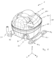
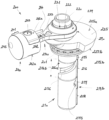
- Fig. 1 shows an outside view of an, in particular hermetically, encapsulated refrigerant compressor 1 which extends along a length direction x, a width direction y and a height direction z.
- Length direction x, width direction y and height direction z form an orthogonal reference system.
- the length dimension of the refrigerant compressor measured along the length direction x is greater than the width dimension measured along the width direction y.
- the refrigerant compressor 1 comprises a compressor shell 100, which in this embodiment consists of a lower shell part 110 and an upper shell part 120.
- the upper shell part 120 and the lower shell part 110 are welded together.
- a supporting base plate 160 is fixed to the compressor shell 100.
- Each supporting base plate 160 has two openings 164 for mounting support damper assemblies 90 (see Fig. 2 ).
- refrigerant is sucked into the refrigerant compressor 1 through the suction pipe 30, mainly during a suction cycle of a pump unit 10 (see Fig. 3 ) of the refrigerant compressor 1. Therefore, in an operating state, the suction pipe 30 is connected directly or indirectly, e.g. through piping of the low pressure side of the refrigerant appliance, to an evaporator of the refrigerant appliance.
- the suction pipe 30 is entering the upper shell part 110 through a second connector element 80, which second connector element 80 is hermetically connected to the upper shell part 120 on the one hand and to the suction pipe 30 on the other hand, for example by welding and/or soldering.
- a discharge pipe 20 as well as a maintenance pipe 40 enters the lower shell part 110 on a front side of the refrigerant compressor 1.
- the discharge pipe 20 enters the lower shell part 110 through a first connector element 70, which first connector element 70 is hermetically connected to the lower shell part 110 on the one hand and to the discharge pipe 20 or maintenance pipe 40 respectively on the other hand, for example by welding and/or soldering.
- first connector element 70 is hermetically connected to the lower shell part 110 on the one hand and to the discharge pipe 20 or maintenance pipe 40 respectively on the other hand, for example by welding and/or soldering.
- refrigerant compressed by the pump unit 10 can escape the refrigerant compressor 1 through the discharge pipe 20, mainly during a compression and discharge cycle of the pump unit 10. Therefore, the discharge pipe 20 is connectable to a high pressure side of the refrigerant appliance to allow compressed refrigerant to be fed to a high pressure side of the refrigerant appliance.
- the discharge pipe 20 is connected directly or indirectly, e.g. through piping
- the maintenance pipe 40 can be used to insert lubrication oil and/or refrigerant into the refrigerant compressor 1 during assembly of the refrigerant application or during maintenance operations.
- the maintenance pipe 40 is, similar to the suction pipe 30, connected to the lower shell part 110 by a second connector element 80, which is hermetically connected to the lower shell part 110 on the one hand and to the maintenance pipe 40 on the other hand, for example by welding and/or soldering.
- the refrigerant compressor 1 comprises the shell 100, an electronic control unit 800, which is detachably mounted to the compressor shell 100, and the pump unit 10 (see Fig. 3 ), which is located inside the compressor shell 100 and supported by four support spring assemblies 60.
- the refrigerant compressor 1 is mounted on four support damper assemblies 90, which are connected to the respective openings of the two supporting base plates 160.
- Each support damper assembly 90 includes a damper pin 92, an outer dampening element 91, a lining disk 93 and a securing element 94.
- the suction pipe 30 enters the upper shell part 120 through a second connection opening 102, whereas the maintenance pipe 20 enters the lower shell part 110 through a third connection opening 103. Even though not visible in Fig. 2 , the discharge pipe 20 enters the lower shell part 110 through a first connection opening 101.
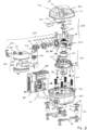
- the pump unit 10 comprises an electric drive unit 400, a cranktrain 200, a crankcase 300 and a cylinder head assembly 500, which includes a suction muffler 600 and a discharge muffler 700.
- Each support spring assembly 60 comprises a mounting pin 140, which is fixed, preferably welded, to the lower shell part 110, a lower spring pin 61, which is mounted on the respective mounting pin 140, and a support spring 62, which is supported on the lower spring pin 61.
- the electric drive unit 400 comprises a stator 420, a rotor 410 and an inner harness 430.
- the stator 420 has a lower end element 421 made of plastic, which lower end element 421 comprises four upper spring holders 63 for the respective support springs 62.
- the stator 420 is fixed to the crankcase 300 via two stator mounting screws 340.
- the inner harness 430 connects the stator 420 with an electric pass-through element 50, which is located in the compressor shell 100.
- the electronic control unit 800 is connected to the electric pass-through element 50 via an outer harness 801, in order to control the rotation speed of the pump unit 10.
- the cranktrain 200 comprises a piston 240 and a crankshaft 210, which is rotatably mounted inside a main bearing section 302 of the crankcase 300 on the one hand and axially supported on the crankcase 300 by a ball bearing 201.
- the crankshaft 210 has a crankpin 220 on which a connecting rod 230 is mounted, which connecting rod 230 connects the crankpin 220 with a piston pin 243 of the piston 240.
- the piston pin 243 is fixed to the piston 240 via a clamping sleeve 244 that is inserted into a matching axial opening in the piston 240 and the piston pin 243.
- the rotor 410 On a lower end of the crankshaft 210, opposite the end with the crankpin 220, the rotor 410 is mounted to the crankshaft 210, preferably via press fitting. Further an oil pickup 250 for conveying lubricant from a lubricant sump formed in the lower shell part 110 during operation into a lubricant conveying system of the cranktrain 200 is mounted to the rotor 410 via three mounting rivets 251.
- the crankcase 300 includes a cylinder housing 310, in which a cylinder 320 is formed.
- the piston 240 reciprocates within the cylinder 320 during operation of the refrigerant compressor 1 in order to suck refrigerant into the cylinder 320 during a suction cycle and to compress and discharge the compressed refrigerant during a compression and discharge cycle.
- a set of two first protrusions 301 is located on the side opposite of the cylinder housing 310 and a set of two second protrusions 311 is located on the cylinder housing 310 itself.
- Inner dampening elements 330 are attached to each of the first protrusions 301 and second protrusions 311, which inner dampening elements 330 interact with respective regions of an inner surface of the upper housing part 120 in order to dampen vibrations of the pump unit 10 during operation and to prevent damages during transport.
- the cylinder head assembly 500 is mounted onto a cylinder head section of the cylinder housing 510.
- the cylinder head assembly 500 comprises a cylinder gasket 510, a suction valve spring 520, a valve plate 530 and a discharge valve spring 540, wherein the valve plate 530 has a suction opening 531 and a discharge opening 532.
- the cylinder gasket 510 and the suction valve spring 520 are located on a suction side 530a of the valve plate 530, which suction side faces towards the piston 240.
- the discharge valve spring 540 is located on a discharge side 530b of the valve plate 530, which faces in the opposite direction of the piston 240.
- the valve plate 530, the suction valve spring 520 and the cylinder gasket 510 are pressed into a valve plate seat 312 of the cylinder housing 310, as will be described below in detail.
- a suction connector head 640 of the suction muffler 600 and a discharge connector head 730 of the discharge muffler 700 are pressed onto the discharge side 530b of the valve plate 530, wherein a first sealing element 550 is placed between the valve plate 530 and the suction connector head 640 as well as the discharge connector head 730, respectively.
- the piston 240 inside the cylinder 320 moves away from the valve plate 530, so that a negative pressure builds up in the cylinder 320, because the suction valve spring 520 keeps the suction opening 531 of the valve plate 530 closed due to its spring force, while the discharge valve spring 540 closes the discharge opening 532 of the valve plate 530.
- the suction valve spring 520 which at least has a section configured as a reed valve, opens the suction opening 531 to allow refrigerant to flow from the suction pipe 30 through the suction muffler 600 into the cylinder 320.
- the piston 240 inside the cylinder 320 moves in the direction of the valve plate 530, so that the refrigerant in the cylinder 320 is compressed, because the discharge valve spring 540 keeps the discharge opening 532 of the valve plate 530 closed due to its spring force, while the suction valve spring 520 keeps the suction opening 531 of the valve plate 530 closed.
- the discharge valve spring 540 which is configured as a reed valve, opens the discharge opening 532 of the valve plate 530 to allow refrigerant to flow from the cylinder 320 through the discharge muffler 700 to the discharge tube 20.
- the suction muffler 600 includes a lower housing part 610, an upper housing part 620 and an inner housing element 630, which is inserted into a suction muffler volume 601 defined by the lower housing part 610 and the upper housing part 620 of the suction muffler 600.
- Refrigerant is sucked into the suction muffler 600 via an inlet opening 621 located in the upper housing part 620 mainly during the suction cycle of the pump unit 10.
- the suction muffler 600 dampens sound based on the well-known Helmholtz principle when refrigerant flows through it, i.e. by chambers formed within the suction muffler 600 which acts as resonators that absorb sound.
- the refrigerant escapes the suction muffler 600 through the suction connector head 640, which is placed above the suction opening 531 of the valve plate 530 and is located on the upper housing part 620 of the suction muffler 600.
- the discharge muffler 700 includes a lower housing part 710, an upper housing part 720 and the discharge connector head 730, which is connected to the upper housing part 720 of the discharge muffler 700.
- compressed refrigerant coming from the discharge opening 532 of the valve plate 530 enters the discharge muffler 700 though the discharge connector head 730.
- the discharge muffler 700 dampens sound based on the well-known Helmholtz principle when refrigerant flows through it, i.e. by chambers formed within the discharge muffler 700 which chambers act as resonators that absorb sound and or by pulsation filtering.
- the compressed refrigerant escapes the discharge muffler 700 through a discharge connection tube 750, which is connected to the discharge tube 20 via connection sleeve 760 and an O-ring seal 762.
- a mounting assembly 580 (see Fig. 3 ), which comprises a clamping element 560 for clamping the valve plate 530 to the valve plate seat 312 and a fixing element 570, which presses the suction connector head 640 and the discharge connector head 730 onto the valve plate 530.
- the fixing element 570 is latched onto the clamping element 560.
- the clamping element 560 further comprises two positioning pins 565 (see Fig. 2 ), which are used for aligning the discharge connector head 730 with the discharge opening 532 and the suction connector head 640 with the suction opening 531 respectively.
- Fig. 3 shows the pump unit 10 of the refrigerant compressor 1 in an assembled state.
- the suction muffler 600 and the discharge muffler 700 are fixed to the cylinder housing 210 via the clamping element 560 and the fixing element 570 of the mounting assembly 580, while the crankshaft 210 is inserted into the crankcase 300 and the stator 420 is surrounding the rotor 410.
- Fig. 4 shows the structure or build-up of an assembled pump unit 10 of the refrigerant compressor 1.
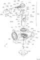
- Fig. 5 shows an exploded view of the pump unit 10 as depicted in Fig. 4 .
- the cranktrain 200 comprises a piston 240 and a crankshaft 210, which is rotatably mounted inside a main bearing section 302 of the crankcase 300 on the one hand and axially supported on the crankcase 300 by a ball bearing 201.
- the crankshaft 210 has a crankshaft axis 211 that indicates the axial direction of the crankshaft 210. Perpendicular to the crankshaft axis 211 is depicted in Fig. 4 via arrows a radial direction 212 of said crankshaft 210.
- the crankshaft 210 transfers the rotating movement from the electric drive unit 400 to the connecting rod 230 and further to the piston 240. It has two bearing sections 215 and 217 which interact with a corresponding main bearing section 302 that acts as a crankshaft bearing shell of the crankcase 300. The two bearing sections 215 and 217 are both arranged in axial direction 211 below the connecting rod 230. Furthermore, a crankpin bearing 223 interacts with the connecting rod 230.
- the rotor 410 is fixed to the bottom side of the crankshaft 210 below the lower bearing section 217 by press-fit.
- the lubrication unit 216 further comprises a lubrication recess 216a that forms a thin lubrication gap in communication with the main bearing section 302 of the crankcase 300.
- An axial length 216b of the lubrication recess 216a corresponds to the axial length of said lubrication section 216 that is positioned between the upper bearing section 215 and the lower bearing section 217.
- crankpin 220 On top of the counterweight 225a, respectively on its upper side 225a, there is the crankpin 220 positioned.
- a crankpin axis 221 runs in parallel with the crankshaft axis 211, wherein the crankpin axis 221 is arranged eccentrically to the crankshaft axis 211.
- the crankpin 221 has a crankpin lubrication recess 222, wherein lubricant that is supplied from a crankpin lubrication bore 223 that is in communication with said crankpin lubrication recess 222, is distributed to lubricate the crankpin sliding bearing 224.
- crankpin 220 of the crankshaft 210 protrudes from a first upper side 225a of the counterweight 225.
- the crankshaft 210 protrudes from an opposite second lower side 225b of the counterweight 225 with regard to the crankpin 220.
- the longitudinal axis 221 of the crankpin 220 is positioned eccentrically and parallel with regard to the longitudinal axis 211 of the crankshaft 210.
- the crankcase 300 has two crankcase legs 303 connected to the stator 420, resulting in a light weight and small component build-up.
- the crankcase 300 has a groove in the back of the cylinder housing 310 to facilitate the assembly of the connecting rod 230 into the crankshaft 210 and following the piston pin 243 and clamping sleeve 244.
- the main bearing section 302 of the crankcase 300 acts as a crankshaft bearing shell, within which the crankshaft 210 is slidably mounted.
- the crankshaft 210 has a first, upper bearing section 215 and has spaced therefrom in an axial distance 216b a second, lower bearing section 217.
- the upper bearing section 215 is configured to interact with the main bearing section 302 as upper bearing journal to form a first, upper sliding bearing 215b.
- the lower bearing section 217 is configured to interact with the main bearing section 302 of the crankcase 300 as lower bearing journal to form a second, lower sliding bearing 217b.
- An upper bearing seat 305 for said upper bearing section 215 of the crankshaft 210 is positioned at an upper end section of the main bearing section 302 of the crankcase 300. Said upper end section of the main bearing section 302 is facing towards the counterweight 225 and facing towards an upper side 300a of the crankcase 300.
- the upper bearing seat 305 is configured to be flexibly bendable in a radial direction 212 of the crankshaft 210 to reduce edge loading of the crankshaft 210 relative to the crankcase 300.
- the upper bearing seat 305 has an inner side 305a and an outer side 305b.
- the inner side 305a faces towards the crankshaft 210.
- the outer side 305b of the upper bearing seat 305 faces towards a bearing recess 308 as can be seen in Fig. 5 .
- the upper bearing seat 305 of the crankcase 300 for the upper bearing section 215 of the crankshaft 210 is designed as a sleeve-shaped cylindrical extension 306 of the crankcase 300 with a wall thickness 307a and an axial height 307b.
- the wall thickness 307a is here for example selected such that the wall thickness 307a is approximately 10% of the diameter of the crankshaft 210.
- the ratio between the axial height 307b and the wall thickness 307a of the sleeve-shaped cylindrical extension 306 is here for example selected as an axial height 307b corresponding 3.5 times the wall thickness 307a.
- the axial height 307b is chosen here as 3.5 times the wall thickness 307a to allow a flexible bending of the sleeve-shaped cylindrical extension 306.
- the wall thickness 307a is here constant along the axial height 307b of the sleeve-shaped cylindrical extension 306.
- the upper bearing seat 305 for the upper bearing section 215 of the crankshaft 210 is formed by a bearing recess 308 within the crankcase 300 that extends from the upper side 300a of the crankcase 300.
- the bearing recess 308 runs concentrically around the outer side 305b of the upper bearing seat 305 downwards in axial direction 211 of the crankshaft 210.
- the bearing recess 308 has an essentially V-shaped cross-section 309 that tapers in regard to the axial direction 211 of the crankshaft 210 towards the main bearing section 302.
- the ball bearing 201 that functions as axial bearing supports the axial load of the rotor 410 and the crankshaft 210 against the crankcase 300.
- the ball bearing is positioned below the counterweight 225, wherein an upper axial bearing seat 202 of the ball bearing 201 is positioned on the lower side 225b of the counterweight 225.
- a lower axial bearing seat 203 of the ball bearing 201 is positioned within said bearing recess 308.
- the ball bearing 201 is advantageously centered in radial direction 212 of the crankshaft 210 by the outer side 305b of the upper bearing seat 305.
- the connecting rod 230 is designed to be flexible for defined compressor operating conditions to compensate for the high crankshaft 210 bending, making the piston 240 run parallel to the cylinder housing 310, and reducing edge loading and friction, even with lower viscosity oils.
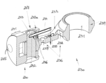
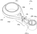
- the connecting rod 230 comprises a big eye bearing 231 on its one end and a small eye bearing 232 on its opposite second end. Both eye bearings 231, 232 are connected with a flexible connecting rod bar 233 that is positioned between both eye bearings 231, 232.
- the flexible connecting rod bar 233 has here two separate damping openings 236 that are oriented in parallel to the big eye bearing 231 and the small eye bearing 232.
- a first damping opening 236 has a circular cross section 237 and a second damping opening 236 has a triangular cross section 238.
- the big eye bearing 231 in a lateral view has a barrel shape 239.
- the small eye bearing 232 there is a lubrication slot 232a that lubricates the sliding bearing of the piston pin 243 in interaction with the small eye bearing 232.
- the lubrication slot 232a functions to receive oil from crankshaft splash and lubricate the small eye bearing 232.
- the flexible connecting rod bar 233 has a rod width 234 and a rod height 235. Flexibility of the connecting rod 230 or the flexible connecting rod bar 233, respectively, can be adjusted via selecting the rod width 234 and/or rod height 235 in combination by appropriate positioning of damping openings 236.
- the piston 240 has two regions: a first region as piston top 241 that defines the sealing area of the piston 240 towards the cylinder housing 310. The entire perimeter of the piston top 241 is in sliding contact with the cylinder housing 310.
- a second region of the piston 240 is a piston skirt 242, wherein the piston skirt 242 has material on its sides and one piston skirt recess 242a on its upper side as well as another one piston skirt recess 242a on its lower side.
- the piston skirt recesses 242a By means of the piston skirt recesses 242a, the contact area along this region of the piston skirt 242 towards the cylinder housing 310 can be reduced. Thus, also friction can be reduced.
- the piston has a protrusion 245 on its top that goes inside the valve plate 530 to reduce the noxious space, increasing the compressor efficiency.
- the piston pin 243 has a piston pin recess 243 to receive oil splashed by the crankshaft 210 to the back of the piston 240 and make it slide down through the piston pin 243 to the small eye lubrication slot 232a of the connecting rod 230, lubricating the small eye bearing 232.
- the connecting rod 230 connects the crankpin 220 with a piston pin 243 of the piston 240.
- the piston pin 243 is fixed to the piston 240 via a clamping sleeve 244 that is inserted into a matching axial opening 246 in the piston 240 and the piston pin 243.
- the clamping sleeve 244 locks the piston pin 243 into a piston pin bore 247 without the need of press-fit. That reduces the deformation on the piston walls, keeping a better cylindricity and allowing smaller piston cylinder clearances, reducing leakage, and improving efficiency.
- the lubricant conveying system of the pump unit 10 comprises an oil pickup 250 for conveying lubricant from a lubricant sump formed in a lower shell part 110 of the compressor shell 100 during operation to the rotating parts of the cranktrain 200.
- the oil pickup 250 is positioned on a lower end of the crankshaft 210.
- the oil pickup 250 is configured to distribute lubricant along an oil path 260 upwards within an inner oil supply bore 254 in axial direction 211 of the crankshaft 210.
- the oil or lubricant is further distributed via a lower lubrication bore 255 to a helical groove 256 that is arranged on an outside of the crankshaft 210 along the peripheral surface of the lubrication section 216, even more precisely that is arranged along the length 216b of the lubrication recess 216a along the lubrication section 216 of the crankshaft 210.
- the lower lubrication bore 255 is positioned at the level of the lower sliding bearing 217b and is in communication to the inner oil supply bore 254.
- oil or lubricant is distributed further via an upper lubrication bore 265 to the ball bearing 201, wherein the upper lubrication bore 265 is positioned at the level of the upper sliding bearing 215b and is in communication to the inner oil supply bore 254.
- Lubricant can be further upwards distributed via a crankpin lubrication bore 275 to an oil splash outlet 280 on top of the crankpin 220.
- the oil splash outlet 280 is configured to lubricate the piston 240.
- the oil path 260 is symbolised via a dotted line 260 with arrows.
- the oil pickup 250 is mounted to the rotor 410, and a helical blade 252 is positioned within the oil pickup 250 and is configured to distribute lubricant that is provided within an oil pump sleeve 253 of the oil pickup 250. Due to a helical blade 252 that reaches into the oil pickup the lubricant is advantageously diverted upwards within the inner oil supply bore 254 of the crankshaft 210 during operation of the compressor 1.
- An inlet of the oil pump sleeve 253 has a degassing bore, here in a preferred embodiment an elongated degassing bore 253a, to improve degassing effects, making it easier for gas bubbles to disappear.
- the rotor 410 is a press-fit fixed to the crankshaft 210.
- the oil pump can be press-fit to the crankshaft 210 as a second process step.
- the oil pump is integrated to the rotor 210 making possible to assembly both in one step, simplifying assembly and reducing cost.
- the inner oil supply bore 254 of the crankshaft 210 in axial direction 211 of the crankshaft 210 has a crankshaft degassing bore 270 on its upper end, wherein the crankshaft degassing bore 270 leads through the counterweight 225 and ends on its upper side 225a. Due to this design, degassing effects are enhanced within the lubricant conveying system. Thus, unwanted dry running of the moving or sliding parts of the compressor 1 can be avoided.
- Fig. 8 shows a three-dimensional view of a first embodiment of a crank train 200 of the refrigerant compressor 1.
- This embodiment of the crank train 200 has been described before and comprises one counterweight 225 that is positioned between the crankpin 220 for the connecting rod 230 and the crankshaft 210 below.
- the counterweight 225 is fully integrated in the crankshaft 210.
- Fig. 9 refers to a second embodiment of a crank train 200 of the refrigerant compressor 1, that has besides a first counterweight 225 an additional second counterweight 226.
- This additional second counterweight 226 is stationary fixed onto the tip of the crankpin 220, wherein the connecting rod 230 is arranged between the first counterweight 225 and the additional second counterweight 226 above the connecting rod 230.
- the additional second counterweight 226 has a degassing bore 227 to improve degassing effects, making it easier for gas bubbles to disappear.
Landscapes
- Engineering & Computer Science (AREA)
- Mechanical Engineering (AREA)
- General Engineering & Computer Science (AREA)
- Compressor (AREA)
Applications Claiming Priority (1)
| Application Number | Priority Date | Filing Date | Title |
|---|---|---|---|
| EP21204555 | 2021-10-25 |
Publications (3)
| Publication Number | Publication Date |
|---|---|
| EP4170164A2 true EP4170164A2 (de) | 2023-04-26 |
| EP4170164A3 EP4170164A3 (de) | 2023-05-10 |
| EP4170164B1 EP4170164B1 (de) | 2025-03-19 |
Family
ID=78536021
Family Applications (1)
| Application Number | Title | Priority Date | Filing Date |
|---|---|---|---|
| EP22203373.0A Active EP4170164B1 (de) | 2021-10-25 | 2022-10-24 | Kältemittelverdichter |
Country Status (2)
| Country | Link |
|---|---|
| EP (1) | EP4170164B1 (de) |
| CN (1) | CN217652875U (de) |
Cited By (3)
| Publication number | Priority date | Publication date | Assignee | Title |
|---|---|---|---|---|
| CN116517840A (zh) * | 2023-05-10 | 2023-08-01 | 潜江市昌贵水产食品股份有限公司 | 螺杆压缩机、输送制冷机构及小龙虾加工方法 |
| CN119508283A (zh) * | 2024-11-29 | 2025-02-25 | 宁波方太厨具有限公司 | 吸振结构及包括其的风机、油烟机 |
| CN119686954A (zh) * | 2024-12-16 | 2025-03-25 | 安徽美芝制冷设备有限公司 | 压缩机以及制冷设备 |
Families Citing this family (1)
| Publication number | Priority date | Publication date | Assignee | Title |
|---|---|---|---|---|
| CN117469129A (zh) * | 2023-05-08 | 2024-01-30 | 安徽美芝制冷设备有限公司 | 往复式压缩机和制冷设备 |
Family Cites Families (17)
| Publication number | Priority date | Publication date | Assignee | Title |
|---|---|---|---|---|
| JP2005023877A (ja) * | 2003-07-04 | 2005-01-27 | Matsushita Electric Ind Co Ltd | 密閉型圧縮機 |
| KR100538940B1 (ko) * | 2003-11-28 | 2005-12-27 | 삼성광주전자 주식회사 | 밀폐형 압축기 |
| BRPI0800686A2 (pt) * | 2008-01-21 | 2009-09-08 | Whirlpool Sa | bomba de óleo para um compressor de refrigeração |
| JP5035413B2 (ja) * | 2008-07-31 | 2012-09-26 | パナソニック株式会社 | 密閉型圧縮機 |
| DE102009005935B4 (de) * | 2009-01-23 | 2010-10-07 | Danfoss Compressors Gmbh | Verfahren zum Kalibrieren einer Pleuelstangenanordnung und Pleuelstangenanordnung |
| WO2011007911A1 (ko) * | 2009-07-17 | 2011-01-20 | (주)엘지전자 | 마모 방지 기구 및 이를 적용한 왕복동식 압축기 |
| BRPI1100652B1 (pt) * | 2011-01-13 | 2021-08-10 | Embraco Indústria De Compressores E Soluções Em Refrigeração Ltda | Arranjo de mancalização para um compressor alternativo de refrigeração |
| BRPI1101929A2 (pt) * | 2011-04-26 | 2015-07-14 | Whirlpool Sa | Biela para compressores de refrigeração |
| JPWO2013099237A1 (ja) * | 2011-12-26 | 2015-04-30 | パナソニックIpマネジメント株式会社 | 密閉型圧縮機およびそれを備える冷蔵庫 |
| KR101910656B1 (ko) * | 2012-04-25 | 2018-10-23 | 삼성전자주식회사 | 밀폐형 왕복동 압축기 |
| DE112014004018T5 (de) * | 2013-09-03 | 2016-07-14 | Panasonic Intellectual Property Management Co., Ltd. | Abgedichteter Kompressor und damit ausgestattete Gefriervorrichtung oder Kühlschrank |
| BR102014007882A2 (pt) * | 2014-04-01 | 2016-01-05 | Whirlpool Sa | arranjo de mancalização radial em um compressor de refrigeração |
| CN106979140B (zh) * | 2016-01-19 | 2021-04-06 | 恩布拉科压缩机工业和制冷解决方案有限公司 | 包括润滑油泵送系统的变速冷却压缩机 |
| CN105570278B (zh) * | 2016-01-28 | 2020-08-14 | 珠海格力电器股份有限公司 | 连杆及往复式压缩机 |
| DE102016001596A1 (de) * | 2016-02-11 | 2017-08-17 | Wabco Gmbh | Hubkolbenmaschine, insbesondere zwei- oder mehrstufiger Kolbenkompressor, Druckluftversorgungsanlage, Druckluftversorgungssystem und Fahrzeug, insbesondere PKW mit einer Druckluftversorgungsanlage |
| CN108496003B (zh) * | 2016-03-07 | 2021-07-06 | 纽摩泰科有限公司 | 小型空气压缩机 |
| JP2018003639A (ja) * | 2016-06-29 | 2018-01-11 | 日立アプライアンス株式会社 | 密閉型圧縮機 |
-
2022
- 2022-01-26 CN CN202220247999.XU patent/CN217652875U/zh active Active
- 2022-10-24 EP EP22203373.0A patent/EP4170164B1/de active Active
Cited By (4)
| Publication number | Priority date | Publication date | Assignee | Title |
|---|---|---|---|---|
| CN116517840A (zh) * | 2023-05-10 | 2023-08-01 | 潜江市昌贵水产食品股份有限公司 | 螺杆压缩机、输送制冷机构及小龙虾加工方法 |
| CN116517840B (zh) * | 2023-05-10 | 2023-11-21 | 潜江市昌贵水产食品股份有限公司 | 螺杆压缩机、输送制冷机构及小龙虾加工方法 |
| CN119508283A (zh) * | 2024-11-29 | 2025-02-25 | 宁波方太厨具有限公司 | 吸振结构及包括其的风机、油烟机 |
| CN119686954A (zh) * | 2024-12-16 | 2025-03-25 | 安徽美芝制冷设备有限公司 | 压缩机以及制冷设备 |
Also Published As
| Publication number | Publication date |
|---|---|
| EP4170164B1 (de) | 2025-03-19 |
| EP4170164A3 (de) | 2023-05-10 |
| CN217652875U (zh) | 2022-10-25 |
Similar Documents
| Publication | Publication Date | Title |
|---|---|---|
| EP4170164A2 (de) | Kältemittelverdichter | |
| CN102272453B (zh) | 往复式压缩机及具有该往复式压缩机的制冷装置 | |
| JP7109666B2 (ja) | コンプレッサー | |
| EP4170166B1 (de) | Verdichtergehäuse für einen kältemittelverdichter | |
| CN1093918C (zh) | 线性压缩机的油路打开和关闭系统 | |
| US10781805B2 (en) | Small air compressor | |
| US10436201B2 (en) | Scroll compressor provided with a lubrication system | |
| KR101951651B1 (ko) | 소형 공기 압축기 | |
| EP4170162B1 (de) | Kältemittelverdichter | |
| WO2016125228A1 (ja) | 圧縮機 | |
| EP4170168A1 (de) | Druckschalldämpfer für einen kältemittelverdichter | |
| EP4170163A1 (de) | Zylinderkopfanordnung | |
| KR101646044B1 (ko) | 밀폐형 압축기 및 이것을 이용한 냉장고 | |
| EP4170167A1 (de) | Saugschalldämpfer für einen kältemittelverdichter | |
| KR101983467B1 (ko) | 왕복동식 압축기 | |
| KR102199012B1 (ko) | 커넥팅로드 및 이를 포함하는 왕복동식 압축기 | |
| KR102418800B1 (ko) | 소형 왕복동식 압축기 | |
| KR100226408B1 (ko) | 압축기의 오일픽업장치 | |
| KR100693142B1 (ko) | 밀폐형 압축기의 오일펌핑장치 | |
| KR20200050678A (ko) | 새로운 피스톤 구조를 갖는 소형 공기 압축기 | |
| KR100524715B1 (ko) | 왕복동식 압축기의 윤활유 공급장치 | |
| KR20090125649A (ko) | 밀폐형 압축기의 마찰 저감 장치 | |
| KR100620046B1 (ko) | 왕복동식 압축기의 윤활유스프링 고정구조 | |
| KR100620031B1 (ko) | 윤활 강화형 스러스트베어링을 가지는 왕복동식 압축기 | |
| KR0133345Y1 (ko) | 횡형 회전압축기 |
Legal Events
| Date | Code | Title | Description |
|---|---|---|---|
| PUAI | Public reference made under article 153(3) epc to a published international application that has entered the european phase |
Free format text: ORIGINAL CODE: 0009012 |
|
| STAA | Information on the status of an ep patent application or granted ep patent |
Free format text: STATUS: THE APPLICATION HAS BEEN PUBLISHED |
|
| PUAL | Search report despatched |
Free format text: ORIGINAL CODE: 0009013 |
|
| AK | Designated contracting states |
Kind code of ref document: A2 Designated state(s): AL AT BE BG CH CY CZ DE DK EE ES FI FR GB GR HR HU IE IS IT LI LT LU LV MC ME MK MT NL NO PL PT RO RS SE SI SK SM TR |
|
| AK | Designated contracting states |
Kind code of ref document: A3 Designated state(s): AL AT BE BG CH CY CZ DE DK EE ES FI FR GB GR HR HU IE IS IT LI LT LU LV MC ME MK MT NL NO PL PT RO RS SE SI SK SM TR |
|
| RIC1 | Information provided on ipc code assigned before grant |
Ipc: F04B 53/00 20060101ALN20230404BHEP Ipc: F04B 53/14 20060101ALI20230404BHEP Ipc: F04B 53/10 20060101ALI20230404BHEP Ipc: F04B 39/12 20060101ALI20230404BHEP Ipc: F04B 39/02 20060101ALI20230404BHEP Ipc: F04B 39/00 20060101ALI20230404BHEP Ipc: F04B 35/04 20060101AFI20230404BHEP |
|
| STAA | Information on the status of an ep patent application or granted ep patent |
Free format text: STATUS: REQUEST FOR EXAMINATION WAS MADE |
|
| 17P | Request for examination filed |
Effective date: 20230928 |
|
| RBV | Designated contracting states (corrected) |
Designated state(s): AL AT BE BG CH CY CZ DE DK EE ES FI FR GB GR HR HU IE IS IT LI LT LU LV MC ME MK MT NL NO PL PT RO RS SE SI SK SM TR |
|
| STAA | Information on the status of an ep patent application or granted ep patent |
Free format text: STATUS: EXAMINATION IS IN PROGRESS |
|
| 17Q | First examination report despatched |
Effective date: 20240829 |
|
| GRAP | Despatch of communication of intention to grant a patent |
Free format text: ORIGINAL CODE: EPIDOSNIGR1 |
|
| STAA | Information on the status of an ep patent application or granted ep patent |
Free format text: STATUS: GRANT OF PATENT IS INTENDED |
|
| RIC1 | Information provided on ipc code assigned before grant |
Ipc: F04B 53/00 20060101ALN20241129BHEP Ipc: F04B 53/14 20060101ALI20241129BHEP Ipc: F04B 53/10 20060101ALI20241129BHEP Ipc: F04B 39/12 20060101ALI20241129BHEP Ipc: F04B 39/02 20060101ALI20241129BHEP Ipc: F04B 39/00 20060101ALI20241129BHEP Ipc: F04B 35/04 20060101AFI20241129BHEP |
|
| RIC1 | Information provided on ipc code assigned before grant |
Ipc: F04B 53/00 20060101ALN20241211BHEP Ipc: F04B 53/14 20060101ALI20241211BHEP Ipc: F04B 53/10 20060101ALI20241211BHEP Ipc: F04B 39/12 20060101ALI20241211BHEP Ipc: F04B 39/02 20060101ALI20241211BHEP Ipc: F04B 39/00 20060101ALI20241211BHEP Ipc: F04B 35/04 20060101AFI20241211BHEP |
|
| INTG | Intention to grant announced |
Effective date: 20241219 |
|
| GRAS | Grant fee paid |
Free format text: ORIGINAL CODE: EPIDOSNIGR3 |
|
| GRAA | (expected) grant |
Free format text: ORIGINAL CODE: 0009210 |
|
| STAA | Information on the status of an ep patent application or granted ep patent |
Free format text: STATUS: THE PATENT HAS BEEN GRANTED |
|
| AK | Designated contracting states |
Kind code of ref document: B1 Designated state(s): AL AT BE BG CH CY CZ DE DK EE ES FI FR GB GR HR HU IE IS IT LI LT LU LV MC ME MK MT NL NO PL PT RO RS SE SI SK SM TR |
|
| REG | Reference to a national code |
Ref country code: GB Ref legal event code: FG4D |
|
| P01 | Opt-out of the competence of the unified patent court (upc) registered |
Free format text: CASE NUMBER: APP_8336/2025 Effective date: 20250219 |
|
| REG | Reference to a national code |
Ref country code: CH Ref legal event code: EP |
|
| REG | Reference to a national code |
Ref country code: IE Ref legal event code: FG4D |
|
| REG | Reference to a national code |
Ref country code: DE Ref legal event code: R096 Ref document number: 602022011925 Country of ref document: DE |
|
| REG | Reference to a national code |
Ref country code: SK Ref legal event code: T3 Ref document number: E 46244 Country of ref document: SK |
|
| PG25 | Lapsed in a contracting state [announced via postgrant information from national office to epo] |
Ref country code: RS Free format text: LAPSE BECAUSE OF FAILURE TO SUBMIT A TRANSLATION OF THE DESCRIPTION OR TO PAY THE FEE WITHIN THE PRESCRIBED TIME-LIMIT Effective date: 20250619 |
|
| PG25 | Lapsed in a contracting state [announced via postgrant information from national office to epo] |
Ref country code: FI Free format text: LAPSE BECAUSE OF FAILURE TO SUBMIT A TRANSLATION OF THE DESCRIPTION OR TO PAY THE FEE WITHIN THE PRESCRIBED TIME-LIMIT Effective date: 20250319 |
|
| REG | Reference to a national code |
Ref country code: LT Ref legal event code: MG9D |
|
| PG25 | Lapsed in a contracting state [announced via postgrant information from national office to epo] |
Ref country code: NO Free format text: LAPSE BECAUSE OF FAILURE TO SUBMIT A TRANSLATION OF THE DESCRIPTION OR TO PAY THE FEE WITHIN THE PRESCRIBED TIME-LIMIT Effective date: 20250619 |
|
| PG25 | Lapsed in a contracting state [announced via postgrant information from national office to epo] |
Ref country code: HR Free format text: LAPSE BECAUSE OF FAILURE TO SUBMIT A TRANSLATION OF THE DESCRIPTION OR TO PAY THE FEE WITHIN THE PRESCRIBED TIME-LIMIT Effective date: 20250319 |
|
| PG25 | Lapsed in a contracting state [announced via postgrant information from national office to epo] |
Ref country code: LV Free format text: LAPSE BECAUSE OF FAILURE TO SUBMIT A TRANSLATION OF THE DESCRIPTION OR TO PAY THE FEE WITHIN THE PRESCRIBED TIME-LIMIT Effective date: 20250319 |
|
| PG25 | Lapsed in a contracting state [announced via postgrant information from national office to epo] |
Ref country code: BG Free format text: LAPSE BECAUSE OF FAILURE TO SUBMIT A TRANSLATION OF THE DESCRIPTION OR TO PAY THE FEE WITHIN THE PRESCRIBED TIME-LIMIT Effective date: 20250319 Ref country code: GR Free format text: LAPSE BECAUSE OF FAILURE TO SUBMIT A TRANSLATION OF THE DESCRIPTION OR TO PAY THE FEE WITHIN THE PRESCRIBED TIME-LIMIT Effective date: 20250620 |
|
| REG | Reference to a national code |
Ref country code: NL Ref legal event code: MP Effective date: 20250319 |
|
| PG25 | Lapsed in a contracting state [announced via postgrant information from national office to epo] |
Ref country code: NL Free format text: LAPSE BECAUSE OF FAILURE TO SUBMIT A TRANSLATION OF THE DESCRIPTION OR TO PAY THE FEE WITHIN THE PRESCRIBED TIME-LIMIT Effective date: 20250319 |
|
| PG25 | Lapsed in a contracting state [announced via postgrant information from national office to epo] |
Ref country code: SE Free format text: LAPSE BECAUSE OF FAILURE TO SUBMIT A TRANSLATION OF THE DESCRIPTION OR TO PAY THE FEE WITHIN THE PRESCRIBED TIME-LIMIT Effective date: 20250319 |
|
| PG25 | Lapsed in a contracting state [announced via postgrant information from national office to epo] |
Ref country code: SM Free format text: LAPSE BECAUSE OF FAILURE TO SUBMIT A TRANSLATION OF THE DESCRIPTION OR TO PAY THE FEE WITHIN THE PRESCRIBED TIME-LIMIT Effective date: 20250319 |
|
| PG25 | Lapsed in a contracting state [announced via postgrant information from national office to epo] |
Ref country code: ES Free format text: LAPSE BECAUSE OF FAILURE TO SUBMIT A TRANSLATION OF THE DESCRIPTION OR TO PAY THE FEE WITHIN THE PRESCRIBED TIME-LIMIT Effective date: 20250319 Ref country code: PT Free format text: LAPSE BECAUSE OF FAILURE TO SUBMIT A TRANSLATION OF THE DESCRIPTION OR TO PAY THE FEE WITHIN THE PRESCRIBED TIME-LIMIT Effective date: 20250721 |
|
| PG25 | Lapsed in a contracting state [announced via postgrant information from national office to epo] |
Ref country code: PL Free format text: LAPSE BECAUSE OF FAILURE TO SUBMIT A TRANSLATION OF THE DESCRIPTION OR TO PAY THE FEE WITHIN THE PRESCRIBED TIME-LIMIT Effective date: 20250319 |
|
| PG25 | Lapsed in a contracting state [announced via postgrant information from national office to epo] |
Ref country code: CZ Free format text: LAPSE BECAUSE OF FAILURE TO SUBMIT A TRANSLATION OF THE DESCRIPTION OR TO PAY THE FEE WITHIN THE PRESCRIBED TIME-LIMIT Effective date: 20250319 Ref country code: EE Free format text: LAPSE BECAUSE OF FAILURE TO SUBMIT A TRANSLATION OF THE DESCRIPTION OR TO PAY THE FEE WITHIN THE PRESCRIBED TIME-LIMIT Effective date: 20250319 |
|
| PG25 | Lapsed in a contracting state [announced via postgrant information from national office to epo] |
Ref country code: RO Free format text: LAPSE BECAUSE OF FAILURE TO SUBMIT A TRANSLATION OF THE DESCRIPTION OR TO PAY THE FEE WITHIN THE PRESCRIBED TIME-LIMIT Effective date: 20250319 |
|
| PGFP | Annual fee paid to national office [announced via postgrant information from national office to epo] |
Ref country code: SK Payment date: 20250930 Year of fee payment: 4 |
|
| PG25 | Lapsed in a contracting state [announced via postgrant information from national office to epo] |
Ref country code: IS Free format text: LAPSE BECAUSE OF FAILURE TO SUBMIT A TRANSLATION OF THE DESCRIPTION OR TO PAY THE FEE WITHIN THE PRESCRIBED TIME-LIMIT Effective date: 20250719 |
|
| REG | Reference to a national code |
Ref country code: DE Ref legal event code: R097 Ref document number: 602022011925 Country of ref document: DE |
|
| PGFP | Annual fee paid to national office [announced via postgrant information from national office to epo] |
Ref country code: DE Payment date: 20250929 Year of fee payment: 4 |
|
| PG25 | Lapsed in a contracting state [announced via postgrant information from national office to epo] |
Ref country code: DK Free format text: LAPSE BECAUSE OF FAILURE TO SUBMIT A TRANSLATION OF THE DESCRIPTION OR TO PAY THE FEE WITHIN THE PRESCRIBED TIME-LIMIT Effective date: 20250319 |
|
| PGFP | Annual fee paid to national office [announced via postgrant information from national office to epo] |
Ref country code: AT Payment date: 20260113 Year of fee payment: 4 |
|
| PGFP | Annual fee paid to national office [announced via postgrant information from national office to epo] |
Ref country code: IT Payment date: 20251031 Year of fee payment: 4 |
|
| PLBE | No opposition filed within time limit |
Free format text: ORIGINAL CODE: 0009261 |
|
| STAA | Information on the status of an ep patent application or granted ep patent |
Free format text: STATUS: NO OPPOSITION FILED WITHIN TIME LIMIT |
|
| REG | Reference to a national code |
Ref country code: CH Ref legal event code: L10 Free format text: ST27 STATUS EVENT CODE: U-0-0-L10-L00 (AS PROVIDED BY THE NATIONAL OFFICE) Effective date: 20260128 |
|
| 26N | No opposition filed |
Effective date: 20251222 |
|
| REG | Reference to a national code |
Ref country code: AT Ref legal event code: UEP Ref document number: 1777146 Country of ref document: AT Kind code of ref document: T Effective date: 20250319 |