EP4170165A1 - Unité de commande électronique pour un compresseur de réfrigérant encapsulé - Google Patents
Unité de commande électronique pour un compresseur de réfrigérant encapsulé Download PDFInfo
- Publication number
- EP4170165A1 EP4170165A1 EP22203374.8A EP22203374A EP4170165A1 EP 4170165 A1 EP4170165 A1 EP 4170165A1 EP 22203374 A EP22203374 A EP 22203374A EP 4170165 A1 EP4170165 A1 EP 4170165A1
- Authority
- EP
- European Patent Office
- Prior art keywords
- control unit
- electronic control
- main housing
- compressor
- circuit board
- Prior art date
- Legal status (The legal status is an assumption and is not a legal conclusion. Google has not performed a legal analysis and makes no representation as to the accuracy of the status listed.)
- Withdrawn
Links
- 239000003507 refrigerant Substances 0.000 title claims abstract description 102
- 238000012423 maintenance Methods 0.000 claims description 14
- 230000000712 assembly Effects 0.000 claims description 7
- 238000000429 assembly Methods 0.000 claims description 7
- 239000004033 plastic Substances 0.000 claims description 6
- 229920003023 plastic Polymers 0.000 claims description 6
- 230000006835 compression Effects 0.000 description 6
- 238000007906 compression Methods 0.000 description 6
- 235000013744 Passiflora ligularis Nutrition 0.000 description 5
- 240000004520 Passiflora ligularis Species 0.000 description 5
- 238000007373 indentation Methods 0.000 description 4
- 238000005520 cutting process Methods 0.000 description 3
- 239000000314 lubricant Substances 0.000 description 3
- 238000005476 soldering Methods 0.000 description 3
- 238000003466 welding Methods 0.000 description 3
- 235000014676 Phragmites communis Nutrition 0.000 description 2
- 229920000122 acrylonitrile butadiene styrene Polymers 0.000 description 2
- 239000004676 acrylonitrile butadiene styrene Substances 0.000 description 2
- 238000005452 bending Methods 0.000 description 2
- 239000003990 capacitor Substances 0.000 description 2
- 238000001746 injection moulding Methods 0.000 description 2
- 238000002372 labelling Methods 0.000 description 2
- 239000002184 metal Substances 0.000 description 2
- 238000000034 method Methods 0.000 description 2
- 238000007789 sealing Methods 0.000 description 2
- 238000009423 ventilation Methods 0.000 description 2
- 238000010521 absorption reaction Methods 0.000 description 1
- XECAHXYUAAWDEL-UHFFFAOYSA-N acrylonitrile butadiene styrene Chemical compound C=CC=C.C=CC#N.C=CC1=CC=CC=C1 XECAHXYUAAWDEL-UHFFFAOYSA-N 0.000 description 1
- 239000000919 ceramic Substances 0.000 description 1
- 238000001914 filtration Methods 0.000 description 1
- 239000011521 glass Substances 0.000 description 1
- 238000005461 lubrication Methods 0.000 description 1
- 238000004519 manufacturing process Methods 0.000 description 1
- 239000000203 mixture Substances 0.000 description 1
- 230000035515 penetration Effects 0.000 description 1
- 239000004417 polycarbonate Substances 0.000 description 1
- 229920000515 polycarbonate Polymers 0.000 description 1
- 229920000642 polymer Polymers 0.000 description 1
- 230000010349 pulsation Effects 0.000 description 1
- 238000005057 refrigeration Methods 0.000 description 1
Images





Classifications
-
- F—MECHANICAL ENGINEERING; LIGHTING; HEATING; WEAPONS; BLASTING
- F04—POSITIVE - DISPLACEMENT MACHINES FOR LIQUIDS; PUMPS FOR LIQUIDS OR ELASTIC FLUIDS
- F04B—POSITIVE-DISPLACEMENT MACHINES FOR LIQUIDS; PUMPS
- F04B35/00—Piston pumps specially adapted for elastic fluids and characterised by the driving means to their working members, or by combination with, or adaptation to, specific driving engines or motors, not otherwise provided for
- F04B35/04—Piston pumps specially adapted for elastic fluids and characterised by the driving means to their working members, or by combination with, or adaptation to, specific driving engines or motors, not otherwise provided for the means being electric
-
- F—MECHANICAL ENGINEERING; LIGHTING; HEATING; WEAPONS; BLASTING
- F04—POSITIVE - DISPLACEMENT MACHINES FOR LIQUIDS; PUMPS FOR LIQUIDS OR ELASTIC FLUIDS
- F04B—POSITIVE-DISPLACEMENT MACHINES FOR LIQUIDS; PUMPS
- F04B39/00—Component parts, details, or accessories, of pumps or pumping systems specially adapted for elastic fluids, not otherwise provided for in, or of interest apart from, groups F04B25/00 - F04B37/00
- F04B39/0027—Pulsation and noise damping means
- F04B39/0044—Pulsation and noise damping means with vibration damping supports
-
- F—MECHANICAL ENGINEERING; LIGHTING; HEATING; WEAPONS; BLASTING
- F04—POSITIVE - DISPLACEMENT MACHINES FOR LIQUIDS; PUMPS FOR LIQUIDS OR ELASTIC FLUIDS
- F04B—POSITIVE-DISPLACEMENT MACHINES FOR LIQUIDS; PUMPS
- F04B39/00—Component parts, details, or accessories, of pumps or pumping systems specially adapted for elastic fluids, not otherwise provided for in, or of interest apart from, groups F04B25/00 - F04B37/00
- F04B39/0027—Pulsation and noise damping means
- F04B39/0055—Pulsation and noise damping means with a special shape of fluid passage, e.g. bends, throttles, diameter changes, pipes
- F04B39/0061—Pulsation and noise damping means with a special shape of fluid passage, e.g. bends, throttles, diameter changes, pipes using muffler volumes
-
- F—MECHANICAL ENGINEERING; LIGHTING; HEATING; WEAPONS; BLASTING
- F04—POSITIVE - DISPLACEMENT MACHINES FOR LIQUIDS; PUMPS FOR LIQUIDS OR ELASTIC FLUIDS
- F04B—POSITIVE-DISPLACEMENT MACHINES FOR LIQUIDS; PUMPS
- F04B39/00—Component parts, details, or accessories, of pumps or pumping systems specially adapted for elastic fluids, not otherwise provided for in, or of interest apart from, groups F04B25/00 - F04B37/00
- F04B39/12—Casings; Cylinders; Cylinder heads; Fluid connections
- F04B39/121—Casings
-
- F—MECHANICAL ENGINEERING; LIGHTING; HEATING; WEAPONS; BLASTING
- F04—POSITIVE - DISPLACEMENT MACHINES FOR LIQUIDS; PUMPS FOR LIQUIDS OR ELASTIC FLUIDS
- F04B—POSITIVE-DISPLACEMENT MACHINES FOR LIQUIDS; PUMPS
- F04B39/00—Component parts, details, or accessories, of pumps or pumping systems specially adapted for elastic fluids, not otherwise provided for in, or of interest apart from, groups F04B25/00 - F04B37/00
- F04B39/12—Casings; Cylinders; Cylinder heads; Fluid connections
- F04B39/125—Cylinder heads
-
- F—MECHANICAL ENGINEERING; LIGHTING; HEATING; WEAPONS; BLASTING
- F04—POSITIVE - DISPLACEMENT MACHINES FOR LIQUIDS; PUMPS FOR LIQUIDS OR ELASTIC FLUIDS
- F04B—POSITIVE-DISPLACEMENT MACHINES FOR LIQUIDS; PUMPS
- F04B53/00—Component parts, details or accessories not provided for in, or of interest apart from, groups F04B1/00 - F04B23/00 or F04B39/00 - F04B47/00
- F04B53/10—Valves; Arrangement of valves
- F04B53/1037—Flap valves
- F04B53/1047—Flap valves the valve being formed by one or more flexible elements
Definitions
- the invention relates to an electronic control unit for an encapsulated refrigerant compressor, the electronic control unit comprising a housing
- Encapsulated, especially hermetically sealed, refrigerant compressors have been known for a long time and are mainly used in refrigeration cabinets, such as refrigerators or refrigerated shelves, but can also be used in mobile appliances.
- the refrigerant process as such has also been known for a long time. Refrigerant is thereby heated by energy absorption from the space to be cooled in an evaporator and finally superheated and pumped to a higher pressure level using the refrigerant compressor having a cylinder and a reciprocating piston.
- the refrigerant is cooled via a condenser and is conveyed back into the evaporator via a throttle, via which throttle the pressure is reduced and the refrigerant is further cooled down, before the cycle starts anew.
- the path of the (usually gaseous) refrigerant through the compressor can be described as follows:
- the refrigerant enters a compressor shell of the refrigerant compressor, which compressor shell encapsulates a pump unit of the refrigerant compressor, through a suction pipe, which is in the operating state connected to the evaporator of the refrigerant appliance.
- the refrigerant is sucked through a suction muffler, a suction opening of a valve plate, which suction opening is released by a suction valve spring, into a cylinder of the pump unit of the refrigerant compressor.
- the suction is caused by linear movement of a piston inside the cylinder.
- the refrigerant is compressed within the cylinder by the linear movement of the piston until a discharge valve spring releases a discharge opening of the valve plate.
- the so compressed refrigerant then flows through the discharge opening of the valve plate into a discharge muffler and leaves the compressor shell through a discharge pipe, which is connected to the discharge muffler by a discharge connection tube.
- the discharge tube is in the operating state connected to the condenser of the refrigerant appliance.
- the pump unit comprises a cranktrain, which includes the piston and is causing the linear movement of the piston inside the cylinder, a crankcase, in which a crankshaft of the cranktrain is mounted, the crankcase also having a cylinder housing, an electric drive unit, which comprises a rotor and a stator, and a cylinder head arrangement.
- the cylinder head arrangement includes the valve plate, the suction valve spring, the discharge valve spring, the suction muffler and the discharge muffler.
- the pump unit is supported within the compressor shell on a plurality of support spring assemblies, preferably on four support spring assemblies.
- the shell usually comprises a lower shell part and an upper shell part, which are welded together.
- the discharge pipe and the suction pipe as well as a maintenance pipe (also known as service pipe) are hermetically connected to the shell.
- the discharge pipe, the suction pipe and the maintenance pipe are also called discharge connector, suction connector and maintenance connector as they are configured to be connected with respective elements with the refrigerant appliance during assembly and/or in the operation state.
- the movement of the piston is caused by rotation of the crankshaft, wherein the piston is connected to a crank-pin of the crankshaft via a connecting rod.
- the electric drive unit is required to facilitate the rotation of the crankshaft, wherein the rotor is fixed to the crankshaft.
- an electronic control unit is mounted to an outside surface of the compressor shell, wherein the stator is connected to an electric pass through element (also known as “fusite") via an inner harness and the electronic control unit is connected to the electric pass through element via an outer harness.
- the electronic control unit powers the stator and thereby controls the rotational speed of the pump unit of the refrigerant compressor.
- the electronic control unit is usually fixed to the compressor in that the housing of the electronic control unit is screwed to the compressor shell wherein at least two screws should be used in the corresponding openings to fix the housing of the electronic control unit to the compressor shell which screws have to be tightened with a screw driver.
- the housing of the electronic control unit can be connected and fixed to the compressor shell without using a screw driver.
- the mounting effort for mounting the electronic control unit to the compressor shell can be reduced.
- this snap-fit connection can withstand high vibration levels so that compressors with such electronic control units are suitable for mobile applications, like for refrigerators situated in vehicles.
- the main housing and the cover are preferably made of plastic, for example from a polymer, e.g. PC-ABS, a blend of Polycarbonate and Acrylonitrile Butadiene Styrene.
- the main housing and the cover are preferably produced by injection molding.
- An opening of a clip means that there is a through-hole in the clip.
- a recess in the clip means that the clip has an indentation but no penetration at this place.
- the electronic control unit controls the compressor based on predefined rules and/or measured values of the compressor.
- the electronic control unit preferably controls the speed of a variable speed drive compressor.
- the electronic control unit serves as an interface between power supply and compressor.
- the electronic control unit can be designed as a multi voltage device so that it can be used both with DC power supply systems and AC power supply systems.
- the electronic control unit can for example be designed to be used with 12V/24V DC and 100-240V AC 50/60Hz.
- the electronic control unit can have a built-in thermal protection which is actuated and stops the compressor operation if the electronic control unit temperature becomes too high.
- first and second clip each are provided with at least one stiffening rib.
- the stiffening rib or ribs help to reinforce the clips and to reduce vibrations of the clips.
- the stiffening rib or ribs preferably are an integral part of the clip.
- the stiffening rib or ribs can run normal to the outer surface of the main housing.
- the stiffening rib can be placed on the outer surface of the clip, i.e. facing away from the other clip.
- Two or more stiffening ribs can be parallel to each other.
- An opening or recess can be situated between two adjacent stiffening ribs.
- At least one internal stiffening rib is provided inside the main housing on a portion of the main housing which runs parallel to the plane of the circuit board.
- the internal stiffening rib increases the stiffness of the housing and reduces vibrations and thus noise.
- the internal stiffening rib is in the direction of the longest dimension of the housing which usually is also the direction of the longest dimension of the circuit board.
- the internal stiffening rib preferably is an integral part of the main housing.
- At least two furrows are provided opposite to each other in the main housing in order to guide the circuit board in the main housing during mounting and to support opposite edges of the circuit board in the mounted state.
- These furrows act as guiding rails during mounting of the circuit board in the main housing.
- the furrows preferably hold the long edges of the usually rectangular circuit board.
- the furrows preferably are an integral part of the main housing.
- At least one support element is provided on a portion of the main housing which runs parallel to the plane of the circuit board, in order to support the circuit board in a direction normal to its plane.
- the support element is in contact with the circuit board when it is in the mounted state within the main housing.
- the support element can be like a pin or like a pin with a head to enlarge the contact area with the circuit board.
- the support element can be designed to press the circuit board further into the furrows, improving the fixation of the circuit board.
- the support element preferably is an integral part of the main housing.
- At least one I-shaped lateral support element is provided inside the main housing which runs normal to the plane of the circuit board, in order to support the circuit board in a direction normal and in a direction parallel to its plane.
- the I-shaped lateral support element provides for lateral support of the the circuit board and reduces rattling noise by the circuit board.
- the cover of the housing is connected to the main housing by snap-fit.
- the cover can easily be mounted to the main housing, e.g. without the use of screws.
- the cover can also be removed from the main housing by opening the snap connectors.
- the cover can again be reassembled with the main housing after opening.
- the snap-fit connection can be achieved by a series of grooves or embosses running around the opening of the main housing and respective grooves or embosses on or in the cover.
- At least one support element for supporting the circuit board is provided inside the cover. So when the cover is mounted on the main housing these support elements will secure the edge and/or two corners of the circuit board which are in contact with the cover.
- Such support element can e.g. be protrusions in the form of an "L”.
- the support elements preferably are an integral part of the cover.
- the cover comprises apertures, for defining a unique position for a plug to be inserted into the cover, which apertures are situated to evacuate air from the volume between circuit board and a portion of the main housing which runs parallel to the plane of the circuit board and which is nearer to the circuit board than an opposite portion of the main housing.
- a plug which is connected to the power supply, is inserted in a respective socket in the cover which socket holds electric connectors, e.g. blade-like connectors, of the circuit board.
- the plug has indentations and/or protrusions which fit to respective indentations and/or protrusions of the socket.
- Such elements are called poka yoke elements.
- these poka yoke elements are designed to include apertures in the cover so that air from the volume between the circuit board and the nearest parallel wall of the main housing can stream out through these apertures. This helps on the one hand to cool this rather narrow volume and on the other hand to reduce sound which is generated by vibrations in this narrow volume.
- the second clip of the main housing comprises an open groove which corresponds to an open groove in a clip of the cover which clip extends parallel to the second clip and is provided adjacent to the second clip.
- These grooves can be used for another fixation of the cover to the main housing, e.g. for a screw and a washer, in addition to e.g. a snap-fit connection between the main housing and the cover.
- additional fixation can be of advantage for harsh conditions, like intense vibrations in a vehicle where the compressor is situated.
- the first clip of the main housing is oriented parallel to the second clip of the main housing and in a second section the distance between first clip and second clip is growing with growing distance to the outer surface of the main housing.
- the clips open up towards their free ends which makes it easier to slip them onto corresponding parts of the compressor shell to achieve the snap-fit between electronic control unit and encapsulated refrigerant compressor.
- the main housing and first and second clip form an integral plastic part. This allows for production of the main housing in one step, e.g. as a plastic part by injection molding, and for a robust connection between the clips and the main housing.
- the invention also encompasses a system comprising an electronic control unit according to the invention and an encapsulated refrigerant compressor,
- the projections are screw heads of screws which are screwed into the support arms.
- the support arms can have one or more bores into which self-cutting screws can be screwed. This can be done before the step of connecting the electronic control unit to the compressor shell so that connecting the electronic control unit to the compressor shell is accomplished by snapping the electronic control unit to the compressor shell.
- connection shield is welded to an outer surface of a lower shell part of the compressor shell, wherein the electronic control unit is mounted to the connection shield, and in that the connection shield has a shield base plate, with an opening for the electric pass through element of the encapsulated refrigerant compressor, and two support arms extending from the shield base plate wherein the opening of the base plate surrounds the electrical pass through element.
- the connection shield is usually an integral metal part. The support arms are produced by bending two opposite ends of the connection shield.
- the size of the electronic control unit should not exceed the size of the compressor, so in the operating state the housing of the electronic control unit shall not be higher than the compressor.
- the electric pass through element of the encapsulated refrigerant compressor is situated in the lower shell part of the compressor then the electric connecting element of the electronic control unit will also be situated in a lower part of the electronic control unit. So the mechanic and electric connection between electronic control unit and compressor shell will be in the lower part of the electronic control unit.
- the heavier electric components, like capacitors and coils, which are mounted on the circuit board will advantageously be situated nearer to the top of the electronic control unit.
- the support arms are bent inwards towards each other. This makes it easier to slide the clips onto the support arms, in case the support arms are situated between the clips in the mounted state of the housing.
- the support arms are situated between the clips. This makes it easier to mount the projections, e.g. screw heads of screws, to the support arms since the projections can be mounted from the outside of the support arms.
- the projections e.g. screw heads of screws
- the clips are situated between the support arms, in this case the projections would be on the inside of the support arms.
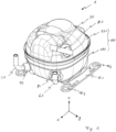
- Fig. 1 shows an outside view of an, in particular hermetically, encapsulated refrigerant compressor 1 which extends along a length direction x, a width direction y and a height direction z.
- Length direction x, width direction y and height direction z form an orthogonal reference system.
- the length dimension of the refrigerant compressor measured along the length direction x is greater than the width dimension measured along the width direction y.
- the refrigerant compressor 1 comprises a compressor shell 100, which in this embodiment consists of a lower shell part 110 and an upper shell part 120.
- the upper shell part 120 and the lower shell part 110 are welded together.
- a supporting base plate 160 is fixed to the compressor shell 100.
- Each supporting base plate 160 has two openings 164 for mounting support damper assemblies 90 (see Fig. 2 ).
- refrigerant is sucked into the refrigerant compressor 1 through the suction pipe 30, mainly during a suction cycle of a pump unit 10 (see Fig. 3 ) of the refrigerant compressor 1. Therefore, in an operating state, the suction pipe 30 is connected directly or indirectly, e.g. through piping of the low pressure side of the refrigerant appliance, to an evaporator of the refrigerant appliance.
- the suction pipe 30 is entering the upper shell part 110 through a second connector element 80, which second connector element 80 is hermetically connected to the upper shell part 120 on the one hand and to the suction pipe 30 on the other hand, for example by welding and/or soldering.
- a discharge pipe 20 as well as a maintenance pipe 40 enters the lower shell part 110 on a front side of the refrigerant compressor 1.
- the discharge pipe 20 enters the lower shell part 110 through a first connector element 70, which first connector element 70 is hermetically connected to the lower shell part 110 on the one hand and to the discharge pipe 20 or maintenance pipe 40 respectively on the other hand, for example by welding and/or soldering.
- first connector element 70 is hermetically connected to the lower shell part 110 on the one hand and to the discharge pipe 20 or maintenance pipe 40 respectively on the other hand, for example by welding and/or soldering.
- refrigerant compressed by the pump unit 10 can escape the refrigerant compressor 1 through the discharge pipe 20, mainly during a compression and discharge cycle of the pump unit 10. Therefore, the discharge pipe 20 is connectable to a high pressure side of the refrigerant appliance to allow compressed refrigerant to be fed to a high pressure side of the refrigerant appliance.
- the discharge pipe 20 is connected directly or indirectly, e.g. through piping of the high pressure side of the refrigerant appliance, to a condenser of the refrigerant appliance.
- the maintenance pipe 40 can be used to insert lubrication oil and/or refrigerant into the refrigerant compressor 1 during assembly of the refrigerant application or during maintenance operations.
- the maintenance pipe 40 is, similar to the suction pipe 30, connected to the lower shell part 110 by a second connector element 80, which is hermetically connected to the lower shell part 110 on the one hand and to the maintenance pipe 40 on the other hand, for example by welding and/or soldering.
- the refrigerant compressor 1 comprises the shell 100, an electronic control unit 800, which is detachably mounted to the compressor shell 100, and the pump unit 10 (see Fig. 3 ), which is located inside the compressor shell 100 and supported by four support spring assemblies 60.
- the refrigerant compressor 1 is mounted on four support damper assemblies 90, which are connected to the respective openings of the two supporting base plates 160.
- Each support damper assembly 90 includes a damper pin 92, an outer dampening element 91, a lining disk 93 and a securing element 94.
- the suction pipe 30 enters the upper shell part 120 through a second connection opening 102, whereas the maintenance pipe 20 enters the lower shell part 110 through a third connection opening 103. Even though not visible in Fig. 2 , the discharge pipe 20 enters the lower shell part 110 through a first connection opening 101.
- the pump unit 10 comprises an electric drive unit 400, a cranktrain 200, a crankcase 300 and a cylinder head assembly 500, which includes a suction muffler 600 and a discharge muffler 700.
- Each support spring assembly 60 comprises a mounting pin 140, which is fixed, preferably welded, to the lower shell part 110, a lower spring pin 61, which is mounted on the respective mounting pin 140, and a support spring 62, which is supported on the lower spring pin 61.
- the electric drive unit 400 comprises a stator 420, a rotor 410 and an inner harness 430.
- the stator 420 has a lower end element 421 made of plastic, which lower end element 421 comprises four upper spring holders 63 for the respective support springs 62.
- the stator 420 is fixed to the crankcase 300 via two stator mounting screws 340.
- the inner harness 430 connects the stator 420 with an electric pass through element 50, which is located in the compressor shell 100.
- the electronic control unit 800 is connected to the electric pass through element 50 via an outer harness 801, in order to control the rotation speed of the pump unit 10.
- the cranktrain 200 comprises a piston 240 and a crankshaft 210, which is rotatably mounted inside a main bearing 302 of the crankcase 300 on the one hand and axially supported on the crankcase 300 by a ball bearing 201.
- the crankshaft 210 has a crank pin 220 on which a connecting rod 230 is mounted, which connecting rod 230 connects the crank pin 220 with a piston pin 243 of the piston 240.
- the piston pin 243 is fixed to the piston 240 via a clamping sleeve 244 that is inserted into a matching axial opening in the piston 240 and the piston pin 243.
- the rotor 410 On a lower end of the crankshaft 210, opposite the end with the crankpin 220, the rotor 410 is mounted to the crankshaft 210, preferably via press fitting. Further an oil pickup 250 for conveying lubricant from a lubricant sump formed in the lower shell part 110 during operation into a lubricant conveying system of the cranktrain 200 is mounted to the rotor 410 via three mounting rivets 251.
- the crankcase 300 includes a cylinder housing 310, in which a cylinder 320 is formed.
- the piston 240 reciprocates within the cylinder 320 during operation of the refrigerant compressor 1 in order to suck refrigerant into the cylinder 320 during a suction cycle and to compress and discharge the compressed refrigerant during a compression and discharge cycle.
- a set of two first protrusions 301 is located on the side opposite of the cylinder housing 310 and a set of two second protrusions 311 is located on the cylinder housing 310 itself.
- Inner dampening elements 330 are attached to each of the first protrusions 301 and second protrusions 311, which inner dampening elements 330 interact with respective regions of an inner surface of the upper housing part 120 in order to dampen vibrations of the pump unit 10 during operation and to prevent damages during transport.
- the cylinder head assembly 500 is mounted onto a cylinder head section of the cylinder housing 310.
- the cylinder head assembly 500 comprises a cylinder gasket 510, a suction valve spring 520, a valve plate 530 and a discharge valve spring 540, wherein the valve plate 530 has a suction opening and a discharge opening.
- the cylinder gasket 510 and the suction valve spring 520 are located on a suction side of the valve plate 530, which suction side faces towards the piston 240.
- the discharge valve spring 540 is located on a discharge side of the valve plate 530, which faces in the opposite direction of the piston 240.
- a suction connector head 640 of the suction muffler 600 and a discharge connector head 730 of the discharge muffler 700 are pressed onto the discharge side of the valve plate 530, wherein a first sealing element 550 is placed between the valve plate 530 and the suction connector head 640 as well as the discharge connector head 730 respectively.
- the piston 240 inside the cylinder 320 moves away from the valve plate 530, so that a negative pressure builds up in the cylinder 320, because the suction valve spring 520 keeps the suction opening of the valve plate 530 closed due to its spring force, while the discharge valve spring 540 closes the discharge opening of the valve plate 530.
- the suction valve spring 520 which at least has a section configured as a reed valve, opens the suction opening to allow refrigerant to flow from the suction pipe 30 through the suction muffler 600 into the cylinder 320.
- the piston 240 inside the cylinder 320 moves in the direction of the valve plate 530, so that the refrigerant in the cylinder 320 is compressed, because the discharge valve spring 540 keeps the discharge opening of the valve plate 530 closed due to its spring force, while the suction valve spring 520 keeps the suction opening of the valve plate 530 closed.
- the discharge valve spring 540 which is configured as a reed valve, opens the discharge opening of the valve plate 530 to allow refrigerant to flow from the cylinder 320 through the discharge muffler 700 to the discharge tube 20.
- the suction muffler 600 includes a lower housing part 610, an upper housing part 620 and an inner housing element 630, which is inserted into a suction muffler volume defined by the lower housing part 610 and the upper housing part 620 of the suction muffler 600.
- Refrigerant is sucked into the suction muffler 600 via an inlet opening 621 located in the upper housing part 620 mainly during the suction cycle of the pump unit 10.
- the suction muffler 600 dampens sound based on the well-known Helmholtz principle when refrigerant flows through it, i.e. by chambers formed within the suction muffler 600 which act as resonators that absorb sound.
- the refrigerant escapes the suction muffler 600 through the suction connector head 640, which is placed above the suction opening of the valve plate 530 and is located on the upper housing part 620 of the suction muffler 600.
- the discharge muffler 700 includes a lower housing part 710, an upper housing part 720 and the discharge connector head 730, which is connected to the upper housing part 720 of the discharge muffler 700.
- compressed refrigerant coming from the discharge opening of the valve plate 530 enters the discharge muffler 700 though the discharge connector head 730.
- the discharge muffler 700 dampens sound based on the well-known Helmholtz principle when refrigerant flows through it, i.e. by chambers formed within the discharge muffler 700 which chambers act as resonators that absorb sound and or by pulsation filtering.
- the compressed refrigerant escapes the discharge muffler 700 through a discharge connection tube 750, which is connected to the discharge tube 20 via connection sleeve 760 and an O-ring seal.
- a mounting assembly 580 (see Fig. 3 ), which comprises a clamping element 560 for clamping the valve plate 530 to the valve plate seat 312 and a fixing element 570, which presses the suction connector head 640 and the discharge connector head 730 onto the valve plate 530.
- the fixing element 570 is latched onto the clamping element 560.
- the clamping element 560 further comprises two positioning pins 565 (see Fig. 2 ), which are used for aligning the discharge connector head 730 with the discharge opening and the suction connector head 640 with the suction opening respectively.
- Fig. 3 shows the pump unit 10 of the refrigerant compressor 1 in an assembled state.
- the suction muffler 600 and the discharge muffler 700 are fixed to the cylinder housing 310 via the clamping element 560 and the fixing element 570 of the mounting assembly 580, while the crankshaft 210 is inserted into the crankcase 300 and the stator 420 is surrounding the rotor 410.
- the electronic control unit 800 is mounted to the compressor 1.
- the housing of the electronic control unit 800 comprises a main housing 802 and a cover 803 which here is mounted to the main housing 802.
- a plug which is connected to the power supply, is inserted in a respective socket in the cover 3 which socket holds electric connectors, here blade-like connectors, of the circuit board.
- two sockets one upper socket for a DC power supply and one lower socket for an AC power supply are provided. Corresponding labeling can be seen on the side of cover 803.
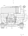
- Fig. 5 shows a sectional view of Fig. 4 for a vertical section parallel to the width direction y in Fig. 1 , cutting through the center of the compressor 1, with its upper 120 and lower shell part 110, and through its electric pass through element 50.
- the electric connecting element 805 here is constructed as a socket which receives the contact pins of the electric pass through element 50 which electric pass through element 50 acts as a plug.
- the circuit board 804 basically extends through the whole main housing 802.
- the heavier and accordingly larger electric components are mounted, here one can see a capacitor. Arranging the heavier components near the top of the housing in the operating state helps to reduce vibrations and thus sound.
- the upper part of the main housing 802 has a greater width in order to accomodate larger electric components. So in this example the wall of the housing 802,803 facing away from the compressor 1 is basically flat whereas the wall of the housing 802,803 facing the compressor 1 has a bulge.
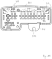
- Fig. 6 shows the electronic control unit 800 without compressor 1. Here the labeling on the side of cover 803 can be seen better.
- the cover 803 On the border to the main housing 802 the cover 803 has two openings with a lug where a tool can be inserted to separate the cover 803 from the main housing 802.
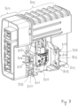
- Fig. 7 shows the electronic control unit 800 with view to the side of the electric connecting element 805.
- the main housing 802 comprises a first 806 and a second clip 807, which clips are protruding, here basically normal, from the outer surface of the main housing 802, wherein the electric connecting element 805 is situated between first 806 and second clip 807.
- the first clip 806 comprises two openings 808, the second clip 807 one opening 808.
- Each clip 806,807 is elastically deformable in a direction parallel to the outer surface of the main housing 802, i.e. parallel to the length direction x (see Fig. 1 ).
- the openings 808 will snap on projections 810 (see Fig. 15 ) on the compressor shell 100 when the electronic control unit 800 is mounted on the compressor shell 100 and electrically connected to the encapsulated refrigerant compressor 1 in order to mechanically fix the electronic control unit 800 on the compressor 1.
- first and second clip 806,807 each are provided with several parallel stiffening ribs 811 running normal to the outer surface of the main housing 802.
- Each opening 808 is situated between two stiffening ribs 811.
- the second clip 807 of the main housing 802 comprises an open groove 809 which corresponds to an open groove 817 in a clip 816 of the cover 803 which clip 816 extends parallel to the second clip 807 and is provided adjacent to the second clip 807.
- These grooves 809,817 can be used for another fixation of the cover 803 to the main housing 802, e.g. for a screw and a washer, in addition to e.g. a snap-fit connection between the main housing 802 and the cover 803.
- first clip 806 of the main housing 802 is oriented parallel to the second clip 807 of the main housing 802.
- the distance between first clip 806 and second clip 807 is growing. So the clips open up towards their free ends which makes it easier to slip them onto corresponding parts of the compressor shell 100 to achieve the snap-fit between electronic control unit 800 and the compressor 1.
- Adjacent to the clips 806,807 further wall elements are provided which protrude, here basically normal, from the outer surface of the main housing 802 and which further surround and enclose the electric connecting element 805, e.g. wall elements which connect the clips 806,807 to the upper part of the main housing 802.
- the electric connecting element 805 can have the terminal plugs attached to a plastic part which is snap-fit to the main housing 802.
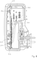
- Fig. 8 shows an enlarged sectional view of the electronic control unit of Fig. 5 .
- the stiffening ribs 812 are an integral part of the main housing 802.
- two furrows 813 which are an integral part of the main housing 802, are provided opposite to each other in order to guide the circuit board 804 in the main housing 802 during mounting and to support opposite edges of the circuit board 804 in the mounted state.
- two support elements 814 are provided on the basically flat wall of the main housing 802 facing away from the compressor shell 100, in order to support the circuit board 804 in a direction normal to its plane (here the width direction y, see Fig. 1 ).
- the support elements 814 are in contact with the circuit board 804.
- the support elements 814 are like a pin with a head to enlarge the contact area with the circuit board 804.
- the support elements 814 press the circuit board 804 further into the furrows 813, improving the fixation of the circuit board 804.
- the support elements 814 are integral part of the main housing 802.
- an I-shaped lateral support element 815 is provided on a portion of the main housing 802 which runs normal to the plane of the circuit board 804, i.e. the wall of the main housing 802 opposite the cover 803.
- the middle part of the "I" in the I-shaped lateral support element 815 fits into a respective horizontal indentation on the back edge of the circuit board 804 and thus prevents vertical movement of the circuit board 804.
- the top and bottom part of the "I" (here both in vertical position) engage on both planar sides of the circuit board 804 and thus prevent lateral movement of the circuit board 804, i.e. movement to the left or to the rigth in Fig. 8 .
- Fig. 9 shows a three dimensional view of the main housing 802 of the electronic control unit 800.
- the cover 803 is removed.
- a series of four grooves running around the opening of the main housing 802 are provided to achieve a snap-fit connection with respective grooves inside the cover 803.
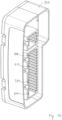
- Fig. 10 shows a three dimensional view of the cover 803 of the housing of the electronic control unit 800.
- the cover 803 comprises apertures 819, for defining a unique position for a plug to be inserted into the cover 803, which apertures 819 are situated to evacuate air from the volume between circuit board 804 and a portion of the main housing 802 which runs parallel to the plane of the circuit board 804 and which is nearer to the circuit board 804 than an opposite portion of the main housing 802.
- This portion of the main housing 802 is the basically flat wall on the left in Fig. 8 which wall also carries the internal stiffening rib 812 and the support elements 814.
- the apertures 819 serve as poka yoke elements and at the same time serve to vent air from inside the rather narrow volume between the circuit board 804 and the basically flat wall of the main housing 802 depicted on the left in Fig. 8 .
- Fig. 11 shows a rear view of the cover 803 of the housing of the electronic control unit 800.
- the rear view shows the side of the cover 803 which faces towards the main housing 802 when mounted.
- the additional apertures 820 are situated opposite to the apertures 819, wherein openings for the blade-like contacts of the circuit board 804 are provided between apertures 819 and additional apertures 820.
- each support element 818 in the form of protrusions, for supporting the circuit board 804 are provided.
- a pair of support elements 818, each support element 818 in the form of an "L" is situated in two corners of the cover 803 so that their distance within the pair corresponds to the thickness of the circuit board 804.
- the support elements 818 are an integral part of the cover 803.
- the clip 816 with its groove 817 is an integral part of the cover 803.
- Fig. 12 shows a front view of the cover 803 of the housing of the electronic control unit 800.
- the clip 816 has stiffening ribs around its groove 817.
- Fig. 13 shows a front view of the electronic control unit 800 mounted to the compressor 1, i.e. to its compressor shell 100, as shown in Fig. 4 .
- the cover 803 as depicted in Fig. 12 and the second clip 807 (see Fig. 7 ) of the main housing 802 wherein the projection 810, which is a screw head in this embodiment, is now located in the opening 808 (see Fig. 7 ) of second clip 807.
- Fig. 14 shows a front view of the open, i.e. cover 803 is removed, and empty main housing 802 of the electronic control unit 800.
- the main housing 802 comprises internal stiffening ribs 812, two furrows 813, support elements 814 and an I-shaped lateral support element 815 which in this view is situated behind an internal stiffening rib 812 but not connected to the internal stiffening rib 812.
- Fig. 15 shows a sectional view of Fig. 4 parallel to the length direction x in Fig. 1 .
- Two support arms 153 extend from the outer surface of the compressor shell 100 of the compressor 1, wherein the electric pass through element 50 of the compressor 1 is at least partly, i.e. at least with its here three contact pins, situated between the support arms 153.
- the clips 806,807 of the housing 802,803 and the support arms 153 of the compressor shell 100 are designed in a way that the openings 808 of the clips 806,807 are snapped on projections 810 on the support arms 153 when the electronic control unit 800 is mounted on the compressor shell 100 and the electric pass through element 50 of the compressor 1 and the electric connecting element 805 of the electronic control unit 800 are electrically connected to each other.
- the projections 810 are screw heads of screws which are screwed into the support arms 153.
- the support arms 153 have respective bores into which self-cutting screws are screwed. This is usually done before the step of connecting the electronic control unit 800 to the compressor shell 100 so that connecting the electronic control unit 800 to the compressor shell 100 is accomplished by simply snapping the electronic control unit 800 to the compressor shell 100 by using the openings 808 and the projections 810.
- only one projection 810 is provided per clip 806,807.
- only one projection 810 i.e. screw head, is provided for the upper opening 808 of the first clip 806 and only one projection 810 is provided for the only lower opening 808 in the second clip 807.
- connection shield 150 is welded to an outer surface of a lower shell part 110 of the compressor shell 100, wherein the connection shield 150 has a shield base plate 151 with an opening 152 for the electric pass through element 50 of the compressor 1, and wherein the two support arms 153 extend from the shield base plate 151 and the opening 152 of the base plate 151 surrounds the electrical pass through element 50.
- the connection shield 150 is usually an integral metal part and the support arms 153 are produced by bending two opposite ends of the connection shield 150.
- the electric pass through element 50 is a hermetic feedthrough element where the contact pins are encapsulated by glass or ceramic within a metallic body. Such elements are also called Fusite elements.
- Fig. 16 shows a top view of the electronic control unit 800 before mounting to the compressor shell 100.
- the electronic control unit 800 is cut open horizontally to better see the first 806 and second clip 807. Also the empty lower compressor shell 110 is cut horizontally.
- Protruding from the compressor shell 100 the support arms 153 and between the support arms 153 the three contact pins of the electric pass though element 50 can be seen.
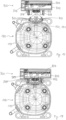
- the support arms 153 are slightly bent inwards towards each other which makes it easier to slide the clips 806,807 onto the support arms 153 so that the support arms 153 are situated between the clips 806,807 in the mounted state of the housing.
- Fig. 17 shows a top view of the the electronic control unit mounted to the compressor, as shown in Fig. 4 .
- the electronic control unit 800 and the lower compressor shell 110 are again cut open horizontally to better see the first 806 and second clip 807 and the support arms 153. It can be seen that when the electronic control unit 800 is mounted on the compressor shell 100 the support arms 153 are situated between the clips 806,807.
Landscapes
- Engineering & Computer Science (AREA)
- Mechanical Engineering (AREA)
- General Engineering & Computer Science (AREA)
- Compressor (AREA)
Applications Claiming Priority (1)
| Application Number | Priority Date | Filing Date | Title |
|---|---|---|---|
| EP21204550 | 2021-10-25 |
Publications (1)
| Publication Number | Publication Date |
|---|---|
| EP4170165A1 true EP4170165A1 (fr) | 2023-04-26 |
Family
ID=78414238
Family Applications (1)
| Application Number | Title | Priority Date | Filing Date |
|---|---|---|---|
| EP22203374.8A Withdrawn EP4170165A1 (fr) | 2021-10-25 | 2022-10-24 | Unité de commande électronique pour un compresseur de réfrigérant encapsulé |
Country Status (2)
| Country | Link |
|---|---|
| EP (1) | EP4170165A1 (fr) |
| CN (1) | CN217712849U (fr) |
Cited By (1)
| Publication number | Priority date | Publication date | Assignee | Title |
|---|---|---|---|---|
| CN119982643A (zh) * | 2025-02-21 | 2025-05-13 | 苏州元脑智能科技有限公司 | 服务器用风扇装置、服务器及风扇装置控制方法 |
Citations (11)
| Publication number | Priority date | Publication date | Assignee | Title |
|---|---|---|---|---|
| US20030147228A1 (en) * | 2002-02-06 | 2003-08-07 | Keihin Corporation | Electronic circuit board fastening member |
| US20040179966A1 (en) * | 2003-03-10 | 2004-09-16 | Sanyo Electric Co., Ltd. | Terminal protective device for compressor, compressor and cold storage chamber |
| WO2007012961A1 (fr) * | 2005-07-29 | 2007-02-01 | Itw Industrial Components S.R.L. Con Unico Socio | Dispositif de plaque à bornes integré pour installation sur une borne étanche au fluide comportant des contacts à broches, en particulier pour les compresseurs |
| EP1845591A2 (fr) * | 2006-04-11 | 2007-10-17 | ITW Industrial Components S.r.l. con Unico Socio | Dispositif d'alimentation et de commande d'un appareil électrique doté d'une borne étanche aux liquides avec contacts de broche, en particulier moteur pour un compresseur d'appareil domestique |
| EP2053322A2 (fr) * | 2007-10-22 | 2009-04-29 | B.D.G. El. S.P.A. | Ensemble pour connexion électrique, le démarrage et la protection d'un moto-compresseur scellé dans une coque métallique hermétique |
| US20120282124A1 (en) * | 2010-11-10 | 2012-11-08 | Emerson Climate Technologies, Inc. | Compressor and enclosure assembly for electrical components |
| EP3196461A2 (fr) * | 2016-01-15 | 2017-07-26 | Whirlpool S.A. | Système, procédé et moyens de connexion et de fixation d'une commande électronique à un compresseur étanche à l'air et compresseur étanche à l'air |
| EP3371452A1 (fr) * | 2015-11-06 | 2018-09-12 | Arçelik Anonim Sirketi | Ensemble carte d'onduleur destiné à être utilisé avec un compresseur hermétique |
| EP3514386A1 (fr) * | 2014-11-10 | 2019-07-24 | LG Electronics Inc. | Compresseur à mouvement alternatif |
| US20200015379A1 (en) * | 2016-10-24 | 2020-01-09 | Mitsubishi Electric Corporation | Vehicle-mounted electronic device |
| WO2020046231A2 (fr) * | 2018-05-29 | 2020-03-05 | Arcelik Anonim Sirketi | Boîtier pour cartes électroniques monté sur un compresseur |
-
2022
- 2022-01-26 CN CN202220244266.0U patent/CN217712849U/zh active Active
- 2022-10-24 EP EP22203374.8A patent/EP4170165A1/fr not_active Withdrawn
Patent Citations (11)
| Publication number | Priority date | Publication date | Assignee | Title |
|---|---|---|---|---|
| US20030147228A1 (en) * | 2002-02-06 | 2003-08-07 | Keihin Corporation | Electronic circuit board fastening member |
| US20040179966A1 (en) * | 2003-03-10 | 2004-09-16 | Sanyo Electric Co., Ltd. | Terminal protective device for compressor, compressor and cold storage chamber |
| WO2007012961A1 (fr) * | 2005-07-29 | 2007-02-01 | Itw Industrial Components S.R.L. Con Unico Socio | Dispositif de plaque à bornes integré pour installation sur une borne étanche au fluide comportant des contacts à broches, en particulier pour les compresseurs |
| EP1845591A2 (fr) * | 2006-04-11 | 2007-10-17 | ITW Industrial Components S.r.l. con Unico Socio | Dispositif d'alimentation et de commande d'un appareil électrique doté d'une borne étanche aux liquides avec contacts de broche, en particulier moteur pour un compresseur d'appareil domestique |
| EP2053322A2 (fr) * | 2007-10-22 | 2009-04-29 | B.D.G. El. S.P.A. | Ensemble pour connexion électrique, le démarrage et la protection d'un moto-compresseur scellé dans une coque métallique hermétique |
| US20120282124A1 (en) * | 2010-11-10 | 2012-11-08 | Emerson Climate Technologies, Inc. | Compressor and enclosure assembly for electrical components |
| EP3514386A1 (fr) * | 2014-11-10 | 2019-07-24 | LG Electronics Inc. | Compresseur à mouvement alternatif |
| EP3371452A1 (fr) * | 2015-11-06 | 2018-09-12 | Arçelik Anonim Sirketi | Ensemble carte d'onduleur destiné à être utilisé avec un compresseur hermétique |
| EP3196461A2 (fr) * | 2016-01-15 | 2017-07-26 | Whirlpool S.A. | Système, procédé et moyens de connexion et de fixation d'une commande électronique à un compresseur étanche à l'air et compresseur étanche à l'air |
| US20200015379A1 (en) * | 2016-10-24 | 2020-01-09 | Mitsubishi Electric Corporation | Vehicle-mounted electronic device |
| WO2020046231A2 (fr) * | 2018-05-29 | 2020-03-05 | Arcelik Anonim Sirketi | Boîtier pour cartes électroniques monté sur un compresseur |
Cited By (1)
| Publication number | Priority date | Publication date | Assignee | Title |
|---|---|---|---|---|
| CN119982643A (zh) * | 2025-02-21 | 2025-05-13 | 苏州元脑智能科技有限公司 | 服务器用风扇装置、服务器及风扇装置控制方法 |
Also Published As
| Publication number | Publication date |
|---|---|
| CN217712849U (zh) | 2022-11-01 |
Similar Documents
| Publication | Publication Date | Title |
|---|---|---|
| USRE47930E1 (en) | Muffler for compressor and compressor having the same | |
| KR102583934B1 (ko) | 압축기 | |
| KR101001576B1 (ko) | 전동식 압축기용 인버터 연결단자 조립체 | |
| EP4170166A1 (fr) | Carter de compresseur pour un compresseur de réfrigérant | |
| KR0143182B1 (ko) | 압축기 | |
| EP4170165A1 (fr) | Unité de commande électronique pour un compresseur de réfrigérant encapsulé | |
| KR0143142B1 (ko) | 왕복동 압축기의 실린더장치 | |
| US20040052660A1 (en) | Electric compressor | |
| KR102198766B1 (ko) | 밀폐형 압축기 | |
| EP4170162B1 (fr) | Compresseur de réfrigérant | |
| US5992170A (en) | Cylinder head-suction muffler assembly for hermetic compressor | |
| CN104251189A (zh) | 马达驱动压缩机 | |
| CN110080983B (zh) | 卧式压缩机 | |
| JPH03290072A (ja) | 密閉型電動圧縮機 | |
| EP4170167B1 (fr) | Silencieux d'aspiration pour compresseur de réfrigérant | |
| KR101854532B1 (ko) | 냉장고의 압축기 조립체 및 이를 구비하는 냉장고 | |
| EP4170163B1 (fr) | Ensemble culasse | |
| US20250350211A1 (en) | Electric compressor | |
| KR20220011535A (ko) | 리니어 압축기 | |
| KR20250147926A (ko) | 전동 압축기 | |
| KR100620045B1 (ko) | 왕복동식 압축기의 윤활유 공급 장치 | |
| KR20060102025A (ko) | 리니어 압축기의 제어박스 고정구조 | |
| KR200308798Y1 (ko) | 밀폐형 압축기용 스토퍼 | |
| KR101212598B1 (ko) | 왕복동식 압축기의 토출밸브 조립체 | |
| CN119755723A (zh) | 电控盒及具有其的空调器 |
Legal Events
| Date | Code | Title | Description |
|---|---|---|---|
| PUAI | Public reference made under article 153(3) epc to a published international application that has entered the european phase |
Free format text: ORIGINAL CODE: 0009012 |
|
| STAA | Information on the status of an ep patent application or granted ep patent |
Free format text: STATUS: THE APPLICATION HAS BEEN PUBLISHED |
|
| AK | Designated contracting states |
Kind code of ref document: A1 Designated state(s): AL AT BE BG CH CY CZ DE DK EE ES FI FR GB GR HR HU IE IS IT LI LT LU LV MC ME MK MT NL NO PL PT RO RS SE SI SK SM TR |
|
| STAA | Information on the status of an ep patent application or granted ep patent |
Free format text: STATUS: THE APPLICATION IS DEEMED TO BE WITHDRAWN |
|
| 18D | Application deemed to be withdrawn |
Effective date: 20231027 |