EP4170177A1 - Pompe à deux cylindres - Google Patents
Pompe à deux cylindres Download PDFInfo
- Publication number
- EP4170177A1 EP4170177A1 EP22194522.3A EP22194522A EP4170177A1 EP 4170177 A1 EP4170177 A1 EP 4170177A1 EP 22194522 A EP22194522 A EP 22194522A EP 4170177 A1 EP4170177 A1 EP 4170177A1
- Authority
- EP
- European Patent Office
- Prior art keywords
- flow
- individual
- fluid
- double pump
- impeller
- Prior art date
- Legal status (The legal status is an assumption and is not a legal conclusion. Google has not performed a legal analysis and makes no representation as to the accuracy of the status listed.)
- Granted
Links
Images

Classifications
-
- F—MECHANICAL ENGINEERING; LIGHTING; HEATING; WEAPONS; BLASTING
- F04—POSITIVE - DISPLACEMENT MACHINES FOR LIQUIDS; PUMPS FOR LIQUIDS OR ELASTIC FLUIDS
- F04D—NON-POSITIVE-DISPLACEMENT PUMPS
- F04D13/00—Pumping installations or systems
- F04D13/12—Combinations of two or more pumps
- F04D13/14—Combinations of two or more pumps the pumps being all of centrifugal type
-
- F—MECHANICAL ENGINEERING; LIGHTING; HEATING; WEAPONS; BLASTING
- F04—POSITIVE - DISPLACEMENT MACHINES FOR LIQUIDS; PUMPS FOR LIQUIDS OR ELASTIC FLUIDS
- F04D—NON-POSITIVE-DISPLACEMENT PUMPS
- F04D29/00—Details, component parts, or accessories
- F04D29/40—Casings; Connections of working fluid
- F04D29/42—Casings; Connections of working fluid for radial or helico-centrifugal pumps
- F04D29/426—Casings; Connections of working fluid for radial or helico-centrifugal pumps especially adapted for liquid pumps
- F04D29/4293—Details of fluid inlet or outlet
-
- F—MECHANICAL ENGINEERING; LIGHTING; HEATING; WEAPONS; BLASTING
- F04—POSITIVE - DISPLACEMENT MACHINES FOR LIQUIDS; PUMPS FOR LIQUIDS OR ELASTIC FLUIDS
- F04D—NON-POSITIVE-DISPLACEMENT PUMPS
- F04D29/00—Details, component parts, or accessories
- F04D29/40—Casings; Connections of working fluid
- F04D29/42—Casings; Connections of working fluid for radial or helico-centrifugal pumps
- F04D29/44—Fluid-guiding means, e.g. diffusers
- F04D29/445—Fluid-guiding means, e.g. diffusers especially adapted for liquid pumps
-
- F—MECHANICAL ENGINEERING; LIGHTING; HEATING; WEAPONS; BLASTING
- F05—INDEXING SCHEMES RELATING TO ENGINES OR PUMPS IN VARIOUS SUBCLASSES OF CLASSES F01-F04
- F05D—INDEXING SCHEME FOR ASPECTS RELATING TO NON-POSITIVE-DISPLACEMENT MACHINES OR ENGINES, GAS-TURBINES OR JET-PROPULSION PLANTS
- F05D2240/00—Components
- F05D2240/10—Stators
- F05D2240/12—Fluid guiding means, e.g. vanes
- F05D2240/126—Baffles or ribs
-
- F—MECHANICAL ENGINEERING; LIGHTING; HEATING; WEAPONS; BLASTING
- F05—INDEXING SCHEMES RELATING TO ENGINES OR PUMPS IN VARIOUS SUBCLASSES OF CLASSES F01-F04
- F05D—INDEXING SCHEME FOR ASPECTS RELATING TO NON-POSITIVE-DISPLACEMENT MACHINES OR ENGINES, GAS-TURBINES OR JET-PROPULSION PLANTS
- F05D2250/00—Geometry
- F05D2250/70—Shape
- F05D2250/71—Shape curved
Definitions
- the invention relates to a double pump with two centrifugal pumps each having impellers arranged therein for conveying a fluid and a suction manifold branching into two individual manifolds for sucking in the fluid, which individual manifolds are connected to a respective suction region of the impellers.
- Double pumps are preferred in order to deliver large delivery volumes when using smaller electric motors and pumps at the same time, or to create redundancy in the delivery circuit.
- double pumps also called twin pumps
- two impellers are arranged in one housing, each impeller being driven by an electric motor to form a single pump.
- Upstream of the impellers is a suction manifold, through which a fluid, such as water in particular, is sucked in at a suction area of the impellers in order to convey the same.
- the suction manifold is usually divided symmetrically into two individual manifolds connected to the respective suction area of the impellers.
- the symmetrical design of the intake manifold leads to a pre-rotation, which is caused by the same direction of rotation of the impellers, namely on the one hand a pre-rotation, which rotates opposite to the direction of rotation of the impeller, and on the other side a pre-rotation, which rotates with the direction of rotation of the impeller.
- the different conditions on the two sides of the double pump result in different behavior in terms of power consumption and hydraulic performance for the respective sides of the double pump.
- Previous flow guides could only compensate for the pre-swirl with considerable flow losses.
- there is an optimal inflow of the impeller directly in front of the impeller existing flow guides cannot be reached. Differences in the flow speed and angle deviations will inevitably remain and are at the expense of the high hydraulic performance that is actually aimed for.
- a double pump with two centrifugal pumps, each with impellers arranged therein for conveying a fluid and a suction manifold branching into two individual manifolds for sucking in the fluid, which individual manifolds are connected to a respective suction area of the impellers, with each individual manifold being spaced apart from a flow guide element is provided for the respective impeller, which flow guide element divides the fluid flowing into the individual manifold into two partial flows and extends in the direction of flow of the fluid towards the impeller, tapering in height.
- An essential point of the invention lies in the shape and arrangement of the flow guidance element in the individual bend, which in the flow channel on the one hand leads to a division of the rotation vortex into two smaller rotation vortices and on the other hand to the generation of a rotation vortex that minimizes or eliminates the remaining counter-vortex.
- the flow is manipulated earlier in the individual manifold compared to the configurations known from the prior art, in order to obtain a maximum equalization of the different flow velocities up to the impeller.
- the flow quality in the sense of the pre-rotation, in the sense of a Angular error as well as a non-uniformity can be optimized.
- an average peripheral speed can be easily controlled, eliminated or even transformed into a pre-spin in the opposite direction.
- the complex control of the individual centrifugal pumps which is otherwise regularly present with double pumps, can be saved for the purpose of optimizing the hydraulic performance.
- the proposed shape of the flow guidance element allows a pump housing of the double pump or the suction manifold of the same to be produced in a particularly simple manner.
- the proposed double pump achieves an almost or even identical and high hydraulic performance, in particular in terms of delivery head, power consumption and/or efficiency, of the two centrifugal pumps and thus of the double pump.
- a turbomachine is generally referred to as a double pump, which uses a rotary movement and dynamic forces to convey predominantly liquids as fluid.
- a centrifugal pump in addition to a tangential acceleration of the liquid, the medium, centrifugal force occurring in radial flow is used for delivery, so that such pumps are also referred to as centrifugal pumps.
- a housing of a motor of the centrifugal pump can be arranged above a pump housing, in which the impeller driven by the motor via the motor shaft is provided for pumping the fluid, the housing of the motor being connected to the pump housing in a stationary manner and/or in one piece can be designed.
- the motor shaft preferably protrudes from the housing of the motor into the pump housing on a drive side and/or the impeller is connected in a stationary manner to the motor shaft on the drive side.
- the fluid preferably comprises a liquid such as water or another liquid medium such as waste water.
- the fluid can include solids such as impurities of any kind, in particular faeces, sediments, dirt, sand, or also smaller pieces of wood, undergrowth, textiles or rags or the like.
- the housing of the motor and/or the pump housing is preferably made of metal, in particular cast iron or stainless steel, and/or plastic.
- the proposed double pump can preferably be used in heating circuits or the like in order in particular to be able to cover peak demand for pumped heating water.
- the double pump can be regulated to a constant or predetermined variable pressure by changing the speed of the individual centrifugal pumps.
- the controller can operate both centrifugal pumps synchronously, i.e. at the same speed, to cover the required flow rate.
- initially only one of the two centrifugal pumps can be used to cover the required flow rate.
- the second centrifugal pump is switched on and continuously increased to cover even larger flow rates, with the first centrifugal pump continuing to run at maximum speed.
- the intake manifold preferably has a round, oval or oval-like cross section, which cross section can change from the branching of the intake manifold into the individual manifolds to the respective impeller.
- the suction manifold preferably has a heart-like shape, with the individual manifolds preferably extending perpendicularly or approximately perpendicularly away from the branch.
- the flow guidance element is preferably of flat design, and can be of rectangular or rectangular design, at least in part or completely.
- the flow guidance element is preferably arranged in the individual manifold in such a way that its flat extension is aligned parallel, approximately or at least partially parallel to the direction of flow.
- the flow guidance element preferably divides the inflowing fluid into two partial flows of the same size or approximately the same size. Likewise, the division based on the resulting vortices can generate such that more fluid can flow in one of the resulting channels than in the other channel.
- the flow guidance element is preferably arranged parallel to the flow. At the end of the flow guidance element facing the impeller, this can be aligned at an angle to the flow for the purpose of generating a swirl.
- Complaints about the impeller means in particular that the flow guidance element is arranged closer to the branching of the individual manifold and/or to the end of the suction manifold opposite the impeller than to the impeller. At a distance can also mean that the flow guidance element is arranged at least 1, 2, 3, 4, 5, 7.5, 10 or more cm away from the impeller. Spaced can also mean that, in the case of a particularly regularly directly in front of the impeller for connection to this essentially orthogonally bent single elbow, the flow guide element is in the direction of flow in front of the bend, in particular 1, 2, 3, 4, 5, 7.5, 10 or more cm before the bend. In other words, at a distance means in particular that the flow guidance element is arranged at a maximum distance from the impeller in the individual manifold.
- Tapering in its height perpendicular to the direction of flow means in particular that the height decreases at a constant rate or at a different rate towards the impeller.
- the height at the end of the flow guidance element facing the branching can be the diameter of the individual manifold, while the height at the end facing the impeller can be only part of the diameter.
- the height in the direction of flow of the fluid can initially be constant and subsequently taper.
- the flow guidance element is designed and arranged in the individual manifold such that the partial flows downstream of the flow guidance element are twist-free or have a desired twist.
- the individual manifold is L-shaped in side view with two legs arranged essentially orthogonally to one another, the shorter leg being connected to the impeller and the flow guide element being arranged in the longer leg.
- the flow-guiding element can be arranged in the longer leg of the L and spaced in this way from the impeller.
- the flow guiding element preferably does not reach into the shorter leg and/or ends in the direction of flow in front of the bend between the longer leg and the shorter leg.
- the flow guidance element is divided into two parts such that the first part facing the inflowing fluid rests on both sides of an inner wall of the individual elbow, in particular touching at its longitudinal edges extending in the flow direction of the fluid, and the second part facing the impeller rests on a part in the flow direction of the fluid extending edge of the individual elbow rests in particular touching and tapers at its opposite edge in height towards the impeller.
- the flow guidance element can extend along at least one longitudinal edge along its entire extent in the direction of flow, in particular touching the inner wall of the individual manifold. Up to the end of the second part facing the impeller, the height can have dropped continuously to zero or, for example, can still be 40 to 60% of the diameter of the individual elbow until shortly before the end.
- the flow guidance element preferably extends along its entire extent with a constant height and/or a height corresponding to the diameter of the individual bend. In this way, the rotation can be subdivided into two smaller rotations consisting of a vortex and a pre-rotation. A counter-vortex can be generated by the second part with a decreasing height, which minimizes or completely eliminates the rotation that may still remain after the first part.
- a length ratio of the two parts in the flow direction of the fluid is 1:4, 1:3, 1:2, 1:1, 2:1, 3:1 or 4:1.
- the first part can extend, for example, 2 cm in the direction of flow, while the second part can extend, for example, 3 cm in the direction of flow, ie the ratio can be 2:3.
- Other ratios, for example odd ratios, are also possible.
- the height of the first part is equal to the diameter of the individual bend.
- the height of the flow guidance element tapers in an S-shape.
- the S-shaped tapering flow guidance element extends between its S-shaped ends almost constantly at a height of ⁇ 40% and ⁇ 60%, in particular 50%, of the diameter of the individual elbow.
- only the second part tapers of the flow guidance element is S-shaped in height, while the first part has a constant height along its longitudinal extension in the direction of flow.
- the S-shaped end facing the first part has a significantly larger radius than the other S-shaped end, so that the height of the flow guidance element initially drops sharply at the transition from the first part to the second part and then, for example, up to the other S-shaped end can run approximately constant in height.
- the ratio of the radii is, for example, 2:1, 3:1, 4:1, 5:1 or 10:1.
- the flow guiding element extends in an S-shape in plan view onto its edge extending in the direction of flow of the fluid.
- the S-shaped end facing the impeller has a substantially larger radius than the S-shaped end facing the branch.
- the ratio of the radii is, for example, 2:1, 3:1, 4:1, 5:1 or 10:1.
- the S-shaped end facing the branching can run out flat, that is, for example, be approximately flat, while the S-shaped end facing the impeller is curved.
- the S-shaped end facing the impeller is preferably bent towards the inner wall of the individual manifold.
- it is preferred that a transverse edge of the flow guidance element facing the inflowing fluid is arranged closer to an inner wall of the individual manifold than an opposite transverse edge of the flow guidance element facing the impeller.
- a flow guide element-free area is provided in the individual manifold between the impeller and the flow guide element and a length ratio of the flow guide element and the flow guide element-free area in the flow direction of the fluid is 1:4, 1:3, 1:2, 1 :1, 2:1, 3:1 or 4:1.
- the flow guide element-free area preferably extends over 1, 2, 3, 4, 5, 7.5, 10 or more cm, as explained above.
- the flow guidance elements of the individual bends are designed and/or arranged symmetrically. Likewise, the flow guidance elements can be designed differently.
- the flow guidance elements of the individual manifolds are arranged next to one another in the area of the branching in such a way that the partial flow of one individual manifold is unaffected by the flow guidance element of the other individual manifold.
- the flow guidance elements do not touch, they can be arranged as close together as possible without influencing the partial flow of the other individual manifold.
- Such an arrangement that is to say in particular away from the impeller and 'close' to one another, can have a positive influence on the flow quality in both individual elbows in order to obtain an improved characteristic of the double pump.
- the flow guidance element is designed in the manner of ribs.
- the flow guidance element is particularly preferably designed as a flat material and/or is injection-molded or cast in one piece and/or together with the intake manifold, in particular made of gray cast iron, investment casting or polyurethane.
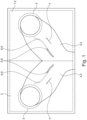
- the double pump 1 shows a double pump 1, also called a twin pump, shown schematically only by a frame, according to a preferred exemplary embodiment of the invention.
- the double pump 1 has two centrifugal pumps 2 arranged therein, also shown schematically only by a dashed frame.
- Each of the two centrifugal pumps 2 has an impeller 3 arranged therein for conveying a fluid such as water in particular, which is also shown schematically only by a dashed frame.
- the double pump 1 has a suction manifold 4 for sucking in the fluid, which is connected to the respective suction areas of the impellers 3 in a fluid-tight manner.
- the heart-shaped intake manifold 4 branches into two individual manifolds 5, which are each connected to the impellers 3.
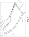
- each individual manifold 5 is as shown in detail in the partially cut-away individual manifolds 5 figs 2 and 3
- a rib-like, flat flow guidance element 6 is provided, by which the fluid flowing into the individual manifold 5 is divided into two sub-flows of substantially the same size.
- a split can also be made in the ratio 55:45, 60:40, 70:30 or exactly 50:50.
- the flow guidance element 6 can be made of a flat material, but in the present case it is injected or cast in one piece with or into the individual manifold 5 and is provided within it at a distance from the respective impeller 3 .
- the flow guiding element 6 extends in the direction of flow 7 of the fluid, indicated by an arrow, towards the impeller 3 , its height narrowing towards the impeller 3 .
- the flow guidance element 6 is designed in two parts, with a first part 8 facing the inflowing fluid extending rectangularly in the individual manifold 5, so that the transverse side facing the inflowing fluid is aligned perpendicular to the flow direction 7 of the fluid and the flow direction 7 of the fluid is essentially parallel to the direction of flow 7 runs.
- the longitudinal edges of the first part 8 touch an inner wall of the individual manifold 5 along their entire extent, so that the flow guide element 6 divides the fluid flow essentially equally.
- the height of the flow guiding element 6 corresponds to the diameter of the individual elbow 5, wherein the individual elbow 5 can also have an oval cross-section and/or a cross-sectional shape that changes along its length in addition to a round cross-section.
- a second part 9 which faces the impeller 3 , adjoins the first part 8 in one piece.
- the height of the second part 9 tapers S-like in the direction of flow 7 of the fluid, starting at the end of the first part 8 with a height corresponding to the diameter of the individual bend 5 and decreasing in the direction of flow 7 .
- a longitudinal edge of the second part 9 as well as the first part 8 touches the inner wall of the individual manifold 5 along its extension in the direction of flow 7 .
- the length ratio of the two parts 8, 9 is 1:1 in the present case, although other ratios such as 1:4, 1:3, 1:2, 2:3, 3:2, 2:1, 3:1 or 4 :1 are conceivable.
- the S-shaped, tapering flow guidance element 6 extends between its S-shaped ends approximately constantly with a height of ⁇ 40% and ⁇ 60%, in this case 50%, of the diameter of the individual elbow 5. while in 2 the S-shaped ends have the same radius, the radius of the S-shaped end in the transition area of the first and second parts 8, 9 is significantly larger than the radius of the S-shaped end of the transverse edge of the flow guidance element 6 facing the impeller 3.
- the height in the direction of flow 7 in the transition area of the first and second parts 8, 9 initially drops sharply, then runs approximately constant in the range of ⁇ 40% and ⁇ 60% of the diameter of the individual manifold 5, and then finally drop to zero at the transverse edge facing the impeller 3.
- the flow guide element 6 In a plan view of its longitudinal edge extending in the direction of flow 7 of the fluid, the flow guide element 6 also extends in an S-shape, as shown in FIG 1 to recognize. While the S-shaped end or the transverse edge of the flow guidance element 6 facing the branching is hardly bent, the S-shaped end or the transverse edge of the flow guidance element 6 facing the impeller 3 has a significantly larger radius of curvature in comparison, so that the transverse edge towards the Inner wall of the single elbow 5 is oriented. Like as well 1 As can be seen, the flow guidance elements 6 of the two individual manifolds 5 are designed symmetrically and are arranged symmetrically in the individual manifolds 5 .
- the flow guide element 6 is arranged at a distance from the impeller 3, namely oriented closer to the junction than to the impeller 3, although not with explicit clarity in FIG 1 shown.
- a flow-guiding element-free area is provided between the impeller 3 and the flow-guiding element 6 .
- the length ratio in the direction of flow between the area free of the flow guide element and the flow guide element 6 is 1:2 in the present case.
- the two flow guidance elements 6 are arranged close to one another in the area of the branching, so that the partial flow of one individual manifold 5 is unaffected by the flow guidance element 6 of the other individual manifold 5 .
- the flow guiding element 6 of one individual elbow 5 can be arranged in the area of the branching adjacent to a virtual hose formed by the flow of the other individual elbow 5 in the individual elbow 5 .
Landscapes
- Engineering & Computer Science (AREA)
- Mechanical Engineering (AREA)
- General Engineering & Computer Science (AREA)
- Structures Of Non-Positive Displacement Pumps (AREA)
Applications Claiming Priority (1)
| Application Number | Priority Date | Filing Date | Title |
|---|---|---|---|
| LU102868A LU102868B1 (de) | 2021-10-20 | 2021-10-20 | Doppelpumpe |
Publications (2)
| Publication Number | Publication Date |
|---|---|
| EP4170177A1 true EP4170177A1 (fr) | 2023-04-26 |
| EP4170177B1 EP4170177B1 (fr) | 2025-06-18 |
Family
ID=78829770
Family Applications (1)
| Application Number | Title | Priority Date | Filing Date |
|---|---|---|---|
| EP22194522.3A Active EP4170177B1 (fr) | 2021-10-20 | 2022-09-08 | Pompe à deux cylindres |
Country Status (2)
| Country | Link |
|---|---|
| EP (1) | EP4170177B1 (fr) |
| LU (1) | LU102868B1 (fr) |
Cited By (1)
| Publication number | Priority date | Publication date | Assignee | Title |
|---|---|---|---|---|
| CN119838840A (zh) * | 2025-03-19 | 2025-04-18 | 宁德时代新能源科技股份有限公司 | 涂布烘箱装置和电池生产系统 |
Citations (3)
| Publication number | Priority date | Publication date | Assignee | Title |
|---|---|---|---|---|
| US1974110A (en) * | 1932-12-21 | 1934-09-18 | Frank R Higley | Curved conduit |
| DE29511718U1 (de) * | 1995-07-20 | 1995-09-07 | Wilo Gmbh, 44263 Dortmund | Flüssigkeitsleitvorrichtung |
| DE19733941A1 (de) * | 1997-08-06 | 1999-02-11 | Klein Schanzlin & Becker Ag | Leitvorrichtung für Rohrleitungskrümmer |
-
2021
- 2021-10-20 LU LU102868A patent/LU102868B1/de active IP Right Grant
-
2022
- 2022-09-08 EP EP22194522.3A patent/EP4170177B1/fr active Active
Patent Citations (3)
| Publication number | Priority date | Publication date | Assignee | Title |
|---|---|---|---|---|
| US1974110A (en) * | 1932-12-21 | 1934-09-18 | Frank R Higley | Curved conduit |
| DE29511718U1 (de) * | 1995-07-20 | 1995-09-07 | Wilo Gmbh, 44263 Dortmund | Flüssigkeitsleitvorrichtung |
| DE19733941A1 (de) * | 1997-08-06 | 1999-02-11 | Klein Schanzlin & Becker Ag | Leitvorrichtung für Rohrleitungskrümmer |
Cited By (1)
| Publication number | Priority date | Publication date | Assignee | Title |
|---|---|---|---|---|
| CN119838840A (zh) * | 2025-03-19 | 2025-04-18 | 宁德时代新能源科技股份有限公司 | 涂布烘箱装置和电池生产系统 |
Also Published As
| Publication number | Publication date |
|---|---|
| EP4170177B1 (fr) | 2025-06-18 |
| LU102868B1 (de) | 2023-04-20 |
Similar Documents
| Publication | Publication Date | Title |
|---|---|---|
| DE69915283T2 (de) | Kreiselrad für turbomaschinen | |
| WO2009127192A1 (fr) | Coude tubulaire à écoulement optimisé | |
| EP3823688A1 (fr) | Conduite d'alimentation pour une unité de pompage d'un système d'assistance cardiaque, système d'assistance cardiaque et procédé destiné à fabriquer une conduite d'alimentation pour une unité de pompe d'un système d'assistance cardiaque | |
| EP0985098B1 (fr) | Pompe centrifuge a dispositif de guidage d'admission | |
| EP2495425A2 (fr) | Dispositif de moteur à réaction doté d'un canal de courant auxiliaire | |
| DE202011000439U1 (de) | Vordüse für ein Antriebssystem eines Wasserfahrzeuges zur Verbesserung der Energieeffizienz | |
| EP1778984B1 (fr) | Forme de canaux pour echangeur de pression rotatif | |
| EP1945337B1 (fr) | Chambre de turbulence | |
| LU102868B1 (de) | Doppelpumpe | |
| EP4706931A2 (fr) | Ensemble raccord de conduites à écoulement optimisé | |
| DE2352641C3 (de) | Zwischenanzapfung fur eine mehrstufige Zentrifugalpumpe | |
| EP3643396B1 (fr) | Dispositif de mélange de fluides fonctionnant en continu et respirant du fluide et son procédé de fonctionnement | |
| DE10258557A1 (de) | Verfahren und Vorrichtung zur Reduktion von Druckschwankungen im Saugrohr einer Wasser-Turbine oder -Pumpe oder -Pumpturbine | |
| EP2935890A2 (fr) | Pompe polyvalente | |
| EP2161455A1 (fr) | Pompe double | |
| DE4041545C2 (fr) | ||
| DE2163011B2 (de) | Seitenkanalarbeitsmaschine | |
| DE102008060943B4 (de) | Mehrflutiges Turbinengehäuse | |
| EP0979354B1 (fr) | Pompe regenerative presentant un canal lateral dans le couvercle d'aspiration pour eviter des structures tourbillonnaires a pertes importantes | |
| DE10343999B3 (de) | Strömungskreis mit Geräuschdämpfung | |
| EP2587067A2 (fr) | Pompe coaxiale multiple | |
| CH650563A5 (en) | Diffuser in a centrifugal driven machine | |
| DE102008039285A1 (de) | Verdichter für eine Brennkraftmaschine | |
| DE19733941A1 (de) | Leitvorrichtung für Rohrleitungskrümmer | |
| DE102023135590B4 (de) | Elliptisch, exzentrischer Ringraum |
Legal Events
| Date | Code | Title | Description |
|---|---|---|---|
| PUAI | Public reference made under article 153(3) epc to a published international application that has entered the european phase |
Free format text: ORIGINAL CODE: 0009012 |
|
| STAA | Information on the status of an ep patent application or granted ep patent |
Free format text: STATUS: THE APPLICATION HAS BEEN PUBLISHED |
|
| AK | Designated contracting states |
Kind code of ref document: A1 Designated state(s): AL AT BE BG CH CY CZ DE DK EE ES FI FR GB GR HR HU IE IS IT LI LT LU LV MC MK MT NL NO PL PT RO RS SE SI SK SM TR |
|
| P01 | Opt-out of the competence of the unified patent court (upc) registered |
Effective date: 20230615 |
|
| STAA | Information on the status of an ep patent application or granted ep patent |
Free format text: STATUS: REQUEST FOR EXAMINATION WAS MADE |
|
| 17P | Request for examination filed |
Effective date: 20231025 |
|
| RBV | Designated contracting states (corrected) |
Designated state(s): AL AT BE BG CH CY CZ DE DK EE ES FI FR GB GR HR HU IE IS IT LI LT LU LV MC MK MT NL NO PL PT RO RS SE SI SK SM TR |
|
| GRAP | Despatch of communication of intention to grant a patent |
Free format text: ORIGINAL CODE: EPIDOSNIGR1 |
|
| STAA | Information on the status of an ep patent application or granted ep patent |
Free format text: STATUS: GRANT OF PATENT IS INTENDED |
|
| INTG | Intention to grant announced |
Effective date: 20250228 |
|
| GRAS | Grant fee paid |
Free format text: ORIGINAL CODE: EPIDOSNIGR3 |
|
| GRAA | (expected) grant |
Free format text: ORIGINAL CODE: 0009210 |
|
| STAA | Information on the status of an ep patent application or granted ep patent |
Free format text: STATUS: THE PATENT HAS BEEN GRANTED |
|
| AK | Designated contracting states |
Kind code of ref document: B1 Designated state(s): AL AT BE BG CH CY CZ DE DK EE ES FI FR GB GR HR HU IE IS IT LI LT LU LV MC MK MT NL NO PL PT RO RS SE SI SK SM TR |
|
| REG | Reference to a national code |
Ref country code: GB Ref legal event code: FG4D Free format text: NOT ENGLISH |
|
| REG | Reference to a national code |
Ref country code: CH Ref legal event code: EP |
|
| REG | Reference to a national code |
Ref country code: DE Ref legal event code: R096 Ref document number: 502022004306 Country of ref document: DE |
|
| REG | Reference to a national code |
Ref country code: CH Ref legal event code: EP |
|
| REG | Reference to a national code |
Ref country code: IE Ref legal event code: FG4D Free format text: LANGUAGE OF EP DOCUMENT: GERMAN |
|
| PG25 | Lapsed in a contracting state [announced via postgrant information from national office to epo] |
Ref country code: FI Free format text: LAPSE BECAUSE OF FAILURE TO SUBMIT A TRANSLATION OF THE DESCRIPTION OR TO PAY THE FEE WITHIN THE PRESCRIBED TIME-LIMIT Effective date: 20250618 |
|
| PGFP | Annual fee paid to national office [announced via postgrant information from national office to epo] |
Ref country code: DE Payment date: 20250820 Year of fee payment: 4 |
|
| REG | Reference to a national code |
Ref country code: LT Ref legal event code: MG9D |
|
| PG25 | Lapsed in a contracting state [announced via postgrant information from national office to epo] |
Ref country code: GR Free format text: LAPSE BECAUSE OF FAILURE TO SUBMIT A TRANSLATION OF THE DESCRIPTION OR TO PAY THE FEE WITHIN THE PRESCRIBED TIME-LIMIT Effective date: 20250919 Ref country code: NO Free format text: LAPSE BECAUSE OF FAILURE TO SUBMIT A TRANSLATION OF THE DESCRIPTION OR TO PAY THE FEE WITHIN THE PRESCRIBED TIME-LIMIT Effective date: 20250918 |
|
| PG25 | Lapsed in a contracting state [announced via postgrant information from national office to epo] |
Ref country code: BG Free format text: LAPSE BECAUSE OF FAILURE TO SUBMIT A TRANSLATION OF THE DESCRIPTION OR TO PAY THE FEE WITHIN THE PRESCRIBED TIME-LIMIT Effective date: 20250618 |
|
| PG25 | Lapsed in a contracting state [announced via postgrant information from national office to epo] |
Ref country code: HR Free format text: LAPSE BECAUSE OF FAILURE TO SUBMIT A TRANSLATION OF THE DESCRIPTION OR TO PAY THE FEE WITHIN THE PRESCRIBED TIME-LIMIT Effective date: 20250618 |
|
| PGFP | Annual fee paid to national office [announced via postgrant information from national office to epo] |
Ref country code: FR Payment date: 20250820 Year of fee payment: 4 Ref country code: AT Payment date: 20251020 Year of fee payment: 4 |
|
| PG25 | Lapsed in a contracting state [announced via postgrant information from national office to epo] |
Ref country code: RS Free format text: LAPSE BECAUSE OF FAILURE TO SUBMIT A TRANSLATION OF THE DESCRIPTION OR TO PAY THE FEE WITHIN THE PRESCRIBED TIME-LIMIT Effective date: 20250918 |
|
| REG | Reference to a national code |
Ref country code: NL Ref legal event code: MP Effective date: 20250618 |
|
| PG25 | Lapsed in a contracting state [announced via postgrant information from national office to epo] |
Ref country code: LV Free format text: LAPSE BECAUSE OF FAILURE TO SUBMIT A TRANSLATION OF THE DESCRIPTION OR TO PAY THE FEE WITHIN THE PRESCRIBED TIME-LIMIT Effective date: 20250618 |
|
| PG25 | Lapsed in a contracting state [announced via postgrant information from national office to epo] |
Ref country code: NL Free format text: LAPSE BECAUSE OF FAILURE TO SUBMIT A TRANSLATION OF THE DESCRIPTION OR TO PAY THE FEE WITHIN THE PRESCRIBED TIME-LIMIT Effective date: 20250618 |
|
| PG25 | Lapsed in a contracting state [announced via postgrant information from national office to epo] |
Ref country code: PT Free format text: LAPSE BECAUSE OF FAILURE TO SUBMIT A TRANSLATION OF THE DESCRIPTION OR TO PAY THE FEE WITHIN THE PRESCRIBED TIME-LIMIT Effective date: 20251020 |
|
| PG25 | Lapsed in a contracting state [announced via postgrant information from national office to epo] |
Ref country code: IS Free format text: LAPSE BECAUSE OF FAILURE TO SUBMIT A TRANSLATION OF THE DESCRIPTION OR TO PAY THE FEE WITHIN THE PRESCRIBED TIME-LIMIT Effective date: 20251018 |
|
| PG25 | Lapsed in a contracting state [announced via postgrant information from national office to epo] |
Ref country code: SM Free format text: LAPSE BECAUSE OF FAILURE TO SUBMIT A TRANSLATION OF THE DESCRIPTION OR TO PAY THE FEE WITHIN THE PRESCRIBED TIME-LIMIT Effective date: 20250618 |
|
| PGFP | Annual fee paid to national office [announced via postgrant information from national office to epo] |
Ref country code: IT Payment date: 20250930 Year of fee payment: 4 |
|
| PG25 | Lapsed in a contracting state [announced via postgrant information from national office to epo] |
Ref country code: CZ Free format text: LAPSE BECAUSE OF FAILURE TO SUBMIT A TRANSLATION OF THE DESCRIPTION OR TO PAY THE FEE WITHIN THE PRESCRIBED TIME-LIMIT Effective date: 20250618 |
|
| PG25 | Lapsed in a contracting state [announced via postgrant information from national office to epo] |
Ref country code: PL Free format text: LAPSE BECAUSE OF FAILURE TO SUBMIT A TRANSLATION OF THE DESCRIPTION OR TO PAY THE FEE WITHIN THE PRESCRIBED TIME-LIMIT Effective date: 20250618 |
|
| PG25 | Lapsed in a contracting state [announced via postgrant information from national office to epo] |
Ref country code: EE Free format text: LAPSE BECAUSE OF FAILURE TO SUBMIT A TRANSLATION OF THE DESCRIPTION OR TO PAY THE FEE WITHIN THE PRESCRIBED TIME-LIMIT Effective date: 20250618 |
|
| PG25 | Lapsed in a contracting state [announced via postgrant information from national office to epo] |
Ref country code: SK Free format text: LAPSE BECAUSE OF FAILURE TO SUBMIT A TRANSLATION OF THE DESCRIPTION OR TO PAY THE FEE WITHIN THE PRESCRIBED TIME-LIMIT Effective date: 20250618 |
|
| PG25 | Lapsed in a contracting state [announced via postgrant information from national office to epo] |
Ref country code: ES Free format text: LAPSE BECAUSE OF FAILURE TO SUBMIT A TRANSLATION OF THE DESCRIPTION OR TO PAY THE FEE WITHIN THE PRESCRIBED TIME-LIMIT Effective date: 20250618 |
|
| PG25 | Lapsed in a contracting state [announced via postgrant information from national office to epo] |
Ref country code: RO Free format text: LAPSE BECAUSE OF FAILURE TO SUBMIT A TRANSLATION OF THE DESCRIPTION OR TO PAY THE FEE WITHIN THE PRESCRIBED TIME-LIMIT Effective date: 20250618 |