EP4170186A1 - Compresseur, en particulier compresseur radial - Google Patents
Compresseur, en particulier compresseur radial Download PDFInfo
- Publication number
- EP4170186A1 EP4170186A1 EP21203945.7A EP21203945A EP4170186A1 EP 4170186 A1 EP4170186 A1 EP 4170186A1 EP 21203945 A EP21203945 A EP 21203945A EP 4170186 A1 EP4170186 A1 EP 4170186A1
- Authority
- EP
- European Patent Office
- Prior art keywords
- compressor
- liquid
- impeller
- injected
- injection
- Prior art date
- Legal status (The legal status is an assumption and is not a legal conclusion. Google has not performed a legal analysis and makes no representation as to the accuracy of the status listed.)
- Withdrawn
Links
- 239000007788 liquid Substances 0.000 claims abstract description 45
- 238000002347 injection Methods 0.000 claims abstract description 40
- 239000007924 injection Substances 0.000 claims abstract description 40
- 238000007906 compression Methods 0.000 claims abstract description 24
- 239000012530 fluid Substances 0.000 claims abstract description 22
- 230000006835 compression Effects 0.000 claims abstract description 18
- 238000000034 method Methods 0.000 claims abstract description 18
- XLYOFNOQVPJJNP-UHFFFAOYSA-N water Substances O XLYOFNOQVPJJNP-UHFFFAOYSA-N 0.000 claims description 15
- OKKJLVBELUTLKV-UHFFFAOYSA-N Methanol Chemical compound OC OKKJLVBELUTLKV-UHFFFAOYSA-N 0.000 claims description 9
- 238000001704 evaporation Methods 0.000 claims description 9
- 230000008020 evaporation Effects 0.000 claims description 9
- 239000000203 mixture Substances 0.000 claims description 8
- LFQSCWFLJHTTHZ-UHFFFAOYSA-N Ethanol Chemical compound CCO LFQSCWFLJHTTHZ-UHFFFAOYSA-N 0.000 claims description 7
- 230000001105 regulatory effect Effects 0.000 claims description 3
- 238000009835 boiling Methods 0.000 description 5
- 238000011161 development Methods 0.000 description 5
- 230000018109 developmental process Effects 0.000 description 5
- 238000002156 mixing Methods 0.000 description 5
- 238000009834 vaporization Methods 0.000 description 4
- 230000008016 vaporization Effects 0.000 description 4
- 238000001816 cooling Methods 0.000 description 3
- 230000001419 dependent effect Effects 0.000 description 2
- 230000000694 effects Effects 0.000 description 2
- 238000009825 accumulation Methods 0.000 description 1
- 238000007792 addition Methods 0.000 description 1
- 230000009286 beneficial effect Effects 0.000 description 1
- 230000000052 comparative effect Effects 0.000 description 1
- 230000003628 erosive effect Effects 0.000 description 1
- 230000014509 gene expression Effects 0.000 description 1
- 230000003116 impacting effect Effects 0.000 description 1
- 238000005381 potential energy Methods 0.000 description 1
Images
Classifications
-
- F—MECHANICAL ENGINEERING; LIGHTING; HEATING; WEAPONS; BLASTING
- F04—POSITIVE - DISPLACEMENT MACHINES FOR LIQUIDS; PUMPS FOR LIQUIDS OR ELASTIC FLUIDS
- F04D—NON-POSITIVE-DISPLACEMENT PUMPS
- F04D17/00—Radial-flow pumps, e.g. centrifugal pumps; Helico-centrifugal pumps
- F04D17/08—Centrifugal pumps
- F04D17/10—Centrifugal pumps for compressing or evacuating
-
- F—MECHANICAL ENGINEERING; LIGHTING; HEATING; WEAPONS; BLASTING
- F04—POSITIVE - DISPLACEMENT MACHINES FOR LIQUIDS; PUMPS FOR LIQUIDS OR ELASTIC FLUIDS
- F04D—NON-POSITIVE-DISPLACEMENT PUMPS
- F04D29/00—Details, component parts, or accessories
- F04D29/40—Casings; Connections of working fluid
- F04D29/42—Casings; Connections of working fluid for radial or helico-centrifugal pumps
- F04D29/4206—Casings; Connections of working fluid for radial or helico-centrifugal pumps especially adapted for elastic fluid pumps
- F04D29/4213—Casings; Connections of working fluid for radial or helico-centrifugal pumps especially adapted for elastic fluid pumps suction ports
-
- F—MECHANICAL ENGINEERING; LIGHTING; HEATING; WEAPONS; BLASTING
- F04—POSITIVE - DISPLACEMENT MACHINES FOR LIQUIDS; PUMPS FOR LIQUIDS OR ELASTIC FLUIDS
- F04D—NON-POSITIVE-DISPLACEMENT PUMPS
- F04D29/00—Details, component parts, or accessories
- F04D29/58—Cooling; Heating; Diminishing heat transfer
- F04D29/582—Cooling; Heating; Diminishing heat transfer specially adapted for elastic fluid pumps
- F04D29/5846—Cooling; Heating; Diminishing heat transfer specially adapted for elastic fluid pumps cooling by injection
-
- F—MECHANICAL ENGINEERING; LIGHTING; HEATING; WEAPONS; BLASTING
- F04—POSITIVE - DISPLACEMENT MACHINES FOR LIQUIDS; PUMPS FOR LIQUIDS OR ELASTIC FLUIDS
- F04D—NON-POSITIVE-DISPLACEMENT PUMPS
- F04D29/00—Details, component parts, or accessories
- F04D29/70—Suction grids; Strainers; Dust separation; Cleaning
- F04D29/701—Suction grids; Strainers; Dust separation; Cleaning especially adapted for elastic fluid pumps
- F04D29/705—Adding liquids
Definitions
- the invention relates to a compressor, in particular a centrifugal compressor.
- water injection is used in raw gas compressors, where the water is injected between the compressor stages in order to reduce the outlet temperature of the medium between the individual stages in order to prevent polymerisation of the medium.
- the limiting degree of vaporization of the liquid injected into the compressor gas stream is problematic. If the liquid is injected into a low velocity area of the compressor, breaking up or atomizing the liquid into very small droplets may not be achieved. Very small droplets are necessary to achieve a high degree of vaporization, because the surface area of such a droplet is large in relation to the volume of the droplet and so the droplet can easily absorb heat and vaporize.
- the object of the invention is to specify an improved compressor, in particular a radial compressor.
- a compressor comprising a rotor which extends along an axis of rotation, a housing, the housing being arranged around the rotor, the housing having an axial inflow and downstream of the axial inflow a first compression stage and further downstream of the first Compression stage having a first radial outflow for a process fluid, the first radial outflow leading through the inner housing, further an impeller, which is arranged on the rotor, with an injection device for injecting a liquid into the axial inflow.
- compression stage means the compression of a specific mass flow by means of one or more compressor impellers.
- compression stage or “compression stage” according to the invention is the compression taking place in an uninterrupted flow path in the compressor, without the mass flow to be compressed or a partial flow thereof being derived from the compressor and possibly being subjected to other process steps.
- a mixture is used as the liquid.
- a further improvement consists in using suitable mixing partners to produce a higher boiling temperature if this is beneficial to the compression process.
- mixing could take place within the medium to be compressed if the enthalpy of mixing is negative and additional (mixing) cooling is to be achieved.
- the aim of the invention is also to approach isothermal compression, which leads to a high level of efficiency.
- the volume flow of the flow can be reduced. With a given cross-section, the speed and the flow losses decrease.
- injection in the spiral stage (last stage of a process stage) is particularly effective.
- an injection device is also proposed in inlets and return stages.
- the amount of liquid should be regulated to ensure an optimal condition close to saturation and to avoid liquid accumulation.
- the amount of water is around 2% by weight.
- the total volume flow including evaporated, added water is reduced by about 8%, which should reduce the losses of a diffuser and a spiral by about 15%.
- Either a gas in liquid aggregate state can be injected or another medium such as water, methanol or ethanol, or a mixture of several components.
- the injected medium is selected so that its evaporation temperature is lower than the temperature at the impeller outlet of the subsequent compression stage without liquid injection, based on the final pressure there.
- the evaporation temperature in the case of mixtures: the lowest-boiling component
- the gas temperature at the point of injection can be lower than the gas temperature at the point of injection.
- the injected medium is chosen so that the evaporation temperature is above the temperature of the compressed gas at the point of injection and below the temperature after of the subsequent compressor stage, based on the case without liquid injection.
- Active dosing of the amount of liquid improves liquid injection.
- the amount of liquid is calculated using the temperature and the relative humidity of the sucked-in medium.
- the dosing can then be done by switching nozzles on and off or via the pump speed or via a by-pass control.
- the dwell time with injected liquid plays a crucial role in the effective humidification of the process fluid.
- a minimum distance between an injection and an impeller inlet of 3 times the impeller inlet diameter is proposed in order to achieve an effective reduction in the compressor drive power by means of liquid injection.
- the distance between the injection and the impeller inlet is essentially 10 times the impeller inlet diameter.
- the relationship applies that the distance between the injection and the impeller inlet can be smaller, the finer the liquid droplets that are introduced.
- cascading of the injection into a plurality of units with a defined distance from one another is proposed. Again should the minimum distance of the last cascade must not be fallen below.
- the injection nozzles in the cascade can be offset from one another, viewed in the direction of flow, in order not to interfere with one another. In a cascaded arrangement, the amount of liquid injected per position can be reduced.
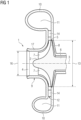
- FIG 1 shows a known radial flow machine in a (simplified) sectional view.
- the flow machine shown is a compressor 1, in particular a centrifugal compressor.
- the turbomachine includes, among other things, a radial impeller 2 which is mounted such that it can rotate about an axis of rotation 3 .
- the impeller 2 has an axial inflow 4 and a radial outflow 5 .
- the impeller 2 comprises a hub 6 and impeller blades 7 protruding radially from the hub 6. Flow channels through which a fluid can flow are formed between the impeller blades 7. Furthermore, the hub 6 is connected to a shaft of the compressor 1 that is not shown in the figure.
- the impeller 2 has a wheel disc 8 which is formed in one piece with the hub 6 and connects the impeller blades 7 to one another.
- the impeller 2 is a so-called open impeller, ie an impeller without a cover disk.
- the impeller 2 could be a so-called closed impeller, ie an impeller with a cover disk.
- the compressor 1 comprises a housing 9 in which the impeller 2 is placed.
- a part of the housing 9 is designed as a spiral housing. That is, the housing 9 has a spiral housing part 10 with a spiral cavity 11 .
- the compressor has an annular diffuser 12 which is axially symmetrical with respect to the axis of rotation 3 is designed as a hollow chamber or as a channel in the housing 9 .
- the diffuser 12 is arranged around a circumference of the impeller 2 and is designed as a radial diffuser.
- the diffuser 12 opens into the spiral housing part 10 or into its cavity 11.
- an outlet diameter 13 of the impeller 2 is indicated in the form of a double arrow.
- the diffuser 12 has a plurality of diffuser vanes 14 . That is, diffuser 12 is a vaned diffuser. In the present exemplary embodiment, the diffuser 12 has six diffuser vanes 14, of which FIG 1 only two are visible. In principle, however, the diffuser 12 could also have a different number of diffuser vanes 14 .
- the compressor 1 is used to compress a fluid such as air.
- a fluid such as air.
- the fluid flows axially through the axial inflow 4 into the impeller 2 or into the flow channels formed by the impeller blades 7.
- the fluid is set in rotation by the impeller 2 and leaves the impeller 2 radially outwards through the radial outflow 5.
- the diffuser 12 converts part of the kinetic energy of the fluid into potential energy in the form of pressure and guides the fluid into the cavity 11 of the volute casing part 10.
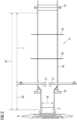
- the figure 2 shows a longitudinal section of a schematic representation of a part of the compressor 1 with an injection device 15 according to the invention figure 2 part of the axial inflow 4 can be seen.
- the double arrow is an impeller inlet diameter 16.
- the impeller inlet 17 is before the in figure 2 not shown impeller 2 arranged.
- An inflow housing 18 is arranged at the impeller inlet 17 and is connected to one another via a plurality of flanges 19 .
- a nozzle 21 is arranged in the inflow housing 18 at a distance 20 .
- the nozzle 21 is designed to supply liquid.
- a process fluid flowing from the right is moved in the direction of the compressor 1 and a liquid gets into the process fluid by means of the nozzles 21 .
- the evaporation temperature of the liquid is lower than the temperature of the process fluid to be compressed after injection in the compression process.
- the injection device 15 has a control device, not shown in detail, which is designed in such a way that the quantity of injected liquid can be controlled.
- the injection device 15 is designed in such a way that the process fluid to be compressed is first sucked in and the quantity of injected liquid depends on the temperature and relative humidity of the sucked-in process fluid.
- the injection device 15 is designed in such a way that the liquid is injected within the process fluid to be compressed.
- the injection device 15 can have a plurality of nozzles 21 (not shown) which are arranged one behind the other in the direction of flow of the process fluid.
- the injection effect is advantageous if the distance 20 between the last nozzle 21 in front of the impeller 2 and the impeller inlet 17 is three times the impeller inlet diameter 16 .
- a further advantageous effect is seen when the distance 20 between the last nozzle 21 in front of the impeller 2 and the impeller inlet 17 is 0.5 to 0.75 times, preferably 0.66 times, the impeller inlet diameter 16 .
- the injection device 15 is particularly effective when the distance 20 between the last nozzle 21 in front of the impeller 2 and the impeller inlet 17 is 10 times the impeller inlet diameter 16 .
- a further possibility of improving the effectiveness of the injection device 15 is achieved by arranging a plurality of nozzles one behind the other in the direction of flow. Improved mixing is possible as a result.
- this improved arrangement is shown schematically by a first line 23 and a second line 24.
- Further nozzles are arranged both on the first line 23 and on the second line 24 .
- the distance between the nozzles 21 and the position that corresponds to 10 times the distance 22 is the length L.
- the distance between the nozzle 21 and the further nozzle at the position on the first line 23 corresponds essentially to one third of the length L .
- the distance between the further nozzles at the first position 23 and the further nozzles at the position on the second line 24 corresponds essentially to one third of the length L.
- the distance between the further nozzles at the second position 24 and the position corresponding to 10 times the distance 22 is essentially one third of the length L.
Landscapes
- Engineering & Computer Science (AREA)
- Mechanical Engineering (AREA)
- General Engineering & Computer Science (AREA)
- Physics & Mathematics (AREA)
- Thermal Sciences (AREA)
- Structures Of Non-Positive Displacement Pumps (AREA)
Priority Applications (6)
| Application Number | Priority Date | Filing Date | Title |
|---|---|---|---|
| EP21203945.7A EP4170186A1 (fr) | 2021-10-21 | 2021-10-21 | Compresseur, en particulier compresseur radial |
| CN202280070551.8A CN118119771A (zh) | 2021-10-21 | 2022-09-22 | 压缩机,尤其径流式压缩机 |
| EP22786802.3A EP4384714A1 (fr) | 2021-10-21 | 2022-09-22 | Compresseur, en particulier compresseur radial |
| PCT/EP2022/076327 WO2023066585A1 (fr) | 2021-10-21 | 2022-09-22 | Compresseur, en particulier compresseur radial |
| JP2024521150A JP2024537237A (ja) | 2021-10-21 | 2022-09-22 | 圧縮機、特に遠心圧縮機 |
| US18/699,345 US20240410378A1 (en) | 2021-10-21 | 2022-09-22 | Radial compressor |
Applications Claiming Priority (1)
| Application Number | Priority Date | Filing Date | Title |
|---|---|---|---|
| EP21203945.7A EP4170186A1 (fr) | 2021-10-21 | 2021-10-21 | Compresseur, en particulier compresseur radial |
Publications (1)
| Publication Number | Publication Date |
|---|---|
| EP4170186A1 true EP4170186A1 (fr) | 2023-04-26 |
Family
ID=78371825
Family Applications (2)
| Application Number | Title | Priority Date | Filing Date |
|---|---|---|---|
| EP21203945.7A Withdrawn EP4170186A1 (fr) | 2021-10-21 | 2021-10-21 | Compresseur, en particulier compresseur radial |
| EP22786802.3A Pending EP4384714A1 (fr) | 2021-10-21 | 2022-09-22 | Compresseur, en particulier compresseur radial |
Family Applications After (1)
| Application Number | Title | Priority Date | Filing Date |
|---|---|---|---|
| EP22786802.3A Pending EP4384714A1 (fr) | 2021-10-21 | 2022-09-22 | Compresseur, en particulier compresseur radial |
Country Status (5)
| Country | Link |
|---|---|
| US (1) | US20240410378A1 (fr) |
| EP (2) | EP4170186A1 (fr) |
| JP (1) | JP2024537237A (fr) |
| CN (1) | CN118119771A (fr) |
| WO (1) | WO2023066585A1 (fr) |
Citations (5)
| Publication number | Priority date | Publication date | Assignee | Title |
|---|---|---|---|---|
| JP2000120596A (ja) * | 1998-10-12 | 2000-04-25 | Ishikawajima Harima Heavy Ind Co Ltd | ターボ圧縮機用の水噴霧装置 |
| JP2009191635A (ja) * | 2008-02-12 | 2009-08-27 | Ihi Corp | ガス機械 |
| JP2011111990A (ja) * | 2009-11-27 | 2011-06-09 | Mitsubishi Heavy Ind Ltd | 遠心圧縮機 |
| EP3441621A1 (fr) * | 2017-08-10 | 2019-02-13 | Siemens Aktiengesellschaft | Turbocompresseur avec injection de gaz de compression liquéfié dans l'écoulement |
| CN107559239B (zh) * | 2017-09-20 | 2019-03-26 | 北京航空航天大学 | 一种具有中心喷嘴结构的离心气体压缩机减温器 |
Family Cites Families (11)
| Publication number | Priority date | Publication date | Assignee | Title |
|---|---|---|---|---|
| JP2877098B2 (ja) * | 1995-12-28 | 1999-03-31 | 株式会社日立製作所 | ガスタービン,コンバインドサイクルプラント及び圧縮機 |
| AU2003224986A1 (en) * | 2002-04-15 | 2003-11-03 | Mee Industries, Inc. | Water injection for gas turbine inlet air |
| AU2002342497A1 (en) * | 2002-06-13 | 2003-12-31 | Alstom Technology Ltd | Method for operating a gas turbine installation, and gas turbine installation |
| US7028485B1 (en) * | 2002-10-02 | 2006-04-18 | Mee Industries, Inc. | Surge prevention for compressor inlet air fogging |
| DE10340177A1 (de) * | 2003-09-01 | 2005-03-31 | Alstom Technology Ltd | Zerstäubungs- und Eindüsensystem, und Verfahren zum Betrieb |
| US7252474B2 (en) * | 2003-09-12 | 2007-08-07 | Mes International, Inc. | Sealing arrangement in a compressor |
| JP5190653B2 (ja) * | 2007-11-14 | 2013-04-24 | 国立大学法人名古屋大学 | 圧縮機 |
| CH705323A1 (de) * | 2011-07-25 | 2013-01-31 | Alstom Technology Ltd | Verfahren zum Einspritzen von Wasser in einen mehrstufigen Axialverdichter einer Gasturbine. |
| CA3006624C (fr) * | 2015-12-11 | 2020-07-21 | Atlas Copco Airpower, Naamloze Vennootschap | Procede de controle de l'injection de liquide d'un dispositif compresseur ou d'expansion, dispositif compresseur ou d'expansion a injection de liquide et un element compresseur oud'expansion a injection de liquide |
| JP6620644B2 (ja) * | 2016-03-31 | 2019-12-18 | 株式会社豊田自動織機 | 遠心圧縮機 |
| FR3088679B1 (fr) * | 2018-11-16 | 2020-12-11 | Safran Helicopter Engines | Circuit d'injection de fluide en amont d'une turbomachine |
-
2021
- 2021-10-21 EP EP21203945.7A patent/EP4170186A1/fr not_active Withdrawn
-
2022
- 2022-09-22 EP EP22786802.3A patent/EP4384714A1/fr active Pending
- 2022-09-22 JP JP2024521150A patent/JP2024537237A/ja active Pending
- 2022-09-22 CN CN202280070551.8A patent/CN118119771A/zh active Pending
- 2022-09-22 US US18/699,345 patent/US20240410378A1/en active Pending
- 2022-09-22 WO PCT/EP2022/076327 patent/WO2023066585A1/fr not_active Ceased
Patent Citations (5)
| Publication number | Priority date | Publication date | Assignee | Title |
|---|---|---|---|---|
| JP2000120596A (ja) * | 1998-10-12 | 2000-04-25 | Ishikawajima Harima Heavy Ind Co Ltd | ターボ圧縮機用の水噴霧装置 |
| JP2009191635A (ja) * | 2008-02-12 | 2009-08-27 | Ihi Corp | ガス機械 |
| JP2011111990A (ja) * | 2009-11-27 | 2011-06-09 | Mitsubishi Heavy Ind Ltd | 遠心圧縮機 |
| EP3441621A1 (fr) * | 2017-08-10 | 2019-02-13 | Siemens Aktiengesellschaft | Turbocompresseur avec injection de gaz de compression liquéfié dans l'écoulement |
| CN107559239B (zh) * | 2017-09-20 | 2019-03-26 | 北京航空航天大学 | 一种具有中心喷嘴结构的离心气体压缩机减温器 |
Also Published As
| Publication number | Publication date |
|---|---|
| WO2023066585A1 (fr) | 2023-04-27 |
| JP2024537237A (ja) | 2024-10-10 |
| US20240410378A1 (en) | 2024-12-12 |
| CN118119771A (zh) | 2024-05-31 |
| EP4384714A1 (fr) | 2024-06-19 |
Similar Documents
| Publication | Publication Date | Title |
|---|---|---|
| DE69621079T2 (de) | Turbomaschine | |
| EP1947299B1 (fr) | Turbosoufflante de gaz d'échappement pour un moteur à combustion interne | |
| EP1609999B1 (fr) | Turbo machine | |
| DE60023216T2 (de) | Vakuumpumpen mit doppeltem einlass | |
| DE2262883A1 (de) | Zentrifugalpumpe mit variablem diffusor | |
| DE4115805A1 (de) | Radialgeblaese mit einem in einem spiralgehaeuse umlaufenden geblaeserad | |
| EP2824282A1 (fr) | Turbine à gaz avec système de refroidissement de turbine à haute pression | |
| DE1428191A1 (de) | Kreiselgeblaese | |
| DE2554010A1 (de) | Vorrichtung und verfahren zur zufuehrung von kuehlluft zu turbinenleitschaufeln | |
| EP1640587B1 (fr) | Système de refroidissement d'une turbine à gaz et méthode de refroidissement d'une turbine à gaz | |
| DE1220204B (de) | Axialturbomaschine, insbesondere Axialgasturbine | |
| DE2454054A1 (de) | Innentriebwerk bzw. gasgenerator fuer gasturbinentriebwerke | |
| WO2006021520A1 (fr) | Injection de fluide dans une turbine a gaz pendant une phase de refroidissement | |
| DE3248440C2 (fr) | ||
| DE112020005428T5 (de) | Variable Düsenvorrichtung, Turbine und Turbolader | |
| EP4170186A1 (fr) | Compresseur, en particulier compresseur radial | |
| DE102010044819B4 (de) | Axialturbine und ein Verfahren zum Abführen eines Stroms von einer Axialturbine | |
| DE102019101277A1 (de) | Axiallüfteranordnung für Fahrzeuge | |
| EP2874558A1 (fr) | Instrument de préparation dentaire | |
| EP2434163A1 (fr) | Compresseur | |
| DE112021007482T5 (de) | Zuführung eines gemischs aus luft und abgas zu einem verdichterrad eines kompressors | |
| AT100901B (de) | Schleuderpumpe. | |
| DE102011117593A1 (de) | Verbesserte Beschauflung für Gleichdruckturbinen mit Überschallströmung | |
| EP3147458A1 (fr) | Système basse pression pour une turbine à vapeur et turbine à vapeur | |
| DE1264957B (de) | Regeleinrichtung fuer Kreiselpumpen |
Legal Events
| Date | Code | Title | Description |
|---|---|---|---|
| PUAI | Public reference made under article 153(3) epc to a published international application that has entered the european phase |
Free format text: ORIGINAL CODE: 0009012 |
|
| STAA | Information on the status of an ep patent application or granted ep patent |
Free format text: STATUS: THE APPLICATION HAS BEEN PUBLISHED |
|
| AK | Designated contracting states |
Kind code of ref document: A1 Designated state(s): AL AT BE BG CH CY CZ DE DK EE ES FI FR GB GR HR HU IE IS IT LI LT LU LV MC MK MT NL NO PL PT RO RS SE SI SK SM TR |
|
| STAA | Information on the status of an ep patent application or granted ep patent |
Free format text: STATUS: THE APPLICATION IS DEEMED TO BE WITHDRAWN |
|
| 18D | Application deemed to be withdrawn |
Effective date: 20231027 |