EP4170187A1 - Hydraulisches antriebssystem - Google Patents
Hydraulisches antriebssystem Download PDFInfo
- Publication number
- EP4170187A1 EP4170187A1 EP21825891.1A EP21825891A EP4170187A1 EP 4170187 A1 EP4170187 A1 EP 4170187A1 EP 21825891 A EP21825891 A EP 21825891A EP 4170187 A1 EP4170187 A1 EP 4170187A1
- Authority
- EP
- European Patent Office
- Prior art keywords
- regeneration
- flow rate
- meter
- working fluid
- valve
- Prior art date
- Legal status (The legal status is an assumption and is not a legal conclusion. Google has not performed a legal analysis and makes no representation as to the accuracy of the status listed.)
- Pending
Links
Images


Classifications
-
- E—FIXED CONSTRUCTIONS
- E02—HYDRAULIC ENGINEERING; FOUNDATIONS; SOIL SHIFTING
- E02F—DREDGING; SOIL-SHIFTING
- E02F9/00—Component parts of dredgers or soil-shifting machines, not restricted to one of the kinds covered by groups E02F3/00 - E02F7/00
- E02F9/20—Drives; Control devices
- E02F9/22—Hydraulic or pneumatic drives
- E02F9/2217—Hydraulic or pneumatic drives with energy recovery arrangements, e.g. using accumulators, flywheels
-
- E—FIXED CONSTRUCTIONS
- E02—HYDRAULIC ENGINEERING; FOUNDATIONS; SOIL SHIFTING
- E02F—DREDGING; SOIL-SHIFTING
- E02F9/00—Component parts of dredgers or soil-shifting machines, not restricted to one of the kinds covered by groups E02F3/00 - E02F7/00
- E02F9/20—Drives; Control devices
- E02F9/22—Hydraulic or pneumatic drives
- E02F9/2221—Control of flow rate; Load sensing arrangements
- E02F9/2225—Control of flow rate; Load sensing arrangements using pressure-compensating valves
- E02F9/2228—Control of flow rate; Load sensing arrangements using pressure-compensating valves including an electronic controller
-
- E—FIXED CONSTRUCTIONS
- E02—HYDRAULIC ENGINEERING; FOUNDATIONS; SOIL SHIFTING
- E02F—DREDGING; SOIL-SHIFTING
- E02F9/00—Component parts of dredgers or soil-shifting machines, not restricted to one of the kinds covered by groups E02F3/00 - E02F7/00
- E02F9/20—Drives; Control devices
- E02F9/22—Hydraulic or pneumatic drives
- E02F9/2278—Hydraulic circuits
- E02F9/2296—Systems with a variable displacement pump
-
- F—MECHANICAL ENGINEERING; LIGHTING; HEATING; WEAPONS; BLASTING
- F15—FLUID-PRESSURE ACTUATORS; HYDRAULICS OR PNEUMATICS IN GENERAL
- F15B—SYSTEMS ACTING BY MEANS OF FLUIDS IN GENERAL; FLUID-PRESSURE ACTUATORS, e.g. SERVOMOTORS; DETAILS OF FLUID-PRESSURE SYSTEMS, NOT OTHERWISE PROVIDED FOR
- F15B11/00—Servomotor systems without provision for follow-up action; Circuits therefor
- F15B11/02—Systems essentially incorporating special features for controlling the speed or actuating force of an output member
- F15B11/024—Systems essentially incorporating special features for controlling the speed or actuating force of an output member by means of differential connection of the servomotor lines, e.g. regenerative circuits
-
- F—MECHANICAL ENGINEERING; LIGHTING; HEATING; WEAPONS; BLASTING
- F15—FLUID-PRESSURE ACTUATORS; HYDRAULICS OR PNEUMATICS IN GENERAL
- F15B—SYSTEMS ACTING BY MEANS OF FLUIDS IN GENERAL; FLUID-PRESSURE ACTUATORS, e.g. SERVOMOTORS; DETAILS OF FLUID-PRESSURE SYSTEMS, NOT OTHERWISE PROVIDED FOR
- F15B11/00—Servomotor systems without provision for follow-up action; Circuits therefor
- F15B11/02—Systems essentially incorporating special features for controlling the speed or actuating force of an output member
- F15B11/04—Systems essentially incorporating special features for controlling the speed or actuating force of an output member for controlling the speed
- F15B11/042—Systems essentially incorporating special features for controlling the speed or actuating force of an output member for controlling the speed by means in the feed line, i.e. "meter in"
-
- F—MECHANICAL ENGINEERING; LIGHTING; HEATING; WEAPONS; BLASTING
- F15—FLUID-PRESSURE ACTUATORS; HYDRAULICS OR PNEUMATICS IN GENERAL
- F15B—SYSTEMS ACTING BY MEANS OF FLUIDS IN GENERAL; FLUID-PRESSURE ACTUATORS, e.g. SERVOMOTORS; DETAILS OF FLUID-PRESSURE SYSTEMS, NOT OTHERWISE PROVIDED FOR
- F15B11/00—Servomotor systems without provision for follow-up action; Circuits therefor
- F15B11/02—Systems essentially incorporating special features for controlling the speed or actuating force of an output member
- F15B11/04—Systems essentially incorporating special features for controlling the speed or actuating force of an output member for controlling the speed
- F15B11/044—Systems essentially incorporating special features for controlling the speed or actuating force of an output member for controlling the speed by means in the return line, i.e. "meter out"
-
- F—MECHANICAL ENGINEERING; LIGHTING; HEATING; WEAPONS; BLASTING
- F15—FLUID-PRESSURE ACTUATORS; HYDRAULICS OR PNEUMATICS IN GENERAL
- F15B—SYSTEMS ACTING BY MEANS OF FLUIDS IN GENERAL; FLUID-PRESSURE ACTUATORS, e.g. SERVOMOTORS; DETAILS OF FLUID-PRESSURE SYSTEMS, NOT OTHERWISE PROVIDED FOR
- F15B11/00—Servomotor systems without provision for follow-up action; Circuits therefor
- F15B11/02—Systems essentially incorporating special features for controlling the speed or actuating force of an output member
- F15B11/024—Systems essentially incorporating special features for controlling the speed or actuating force of an output member by means of differential connection of the servomotor lines, e.g. regenerative circuits
- F15B2011/0246—Systems essentially incorporating special features for controlling the speed or actuating force of an output member by means of differential connection of the servomotor lines, e.g. regenerative circuits with variable regeneration flow
-
- F—MECHANICAL ENGINEERING; LIGHTING; HEATING; WEAPONS; BLASTING
- F15—FLUID-PRESSURE ACTUATORS; HYDRAULICS OR PNEUMATICS IN GENERAL
- F15B—SYSTEMS ACTING BY MEANS OF FLUIDS IN GENERAL; FLUID-PRESSURE ACTUATORS, e.g. SERVOMOTORS; DETAILS OF FLUID-PRESSURE SYSTEMS, NOT OTHERWISE PROVIDED FOR
- F15B2211/00—Circuits for servomotor systems
- F15B2211/20—Fluid pressure source, e.g. accumulator or variable axial piston pump
- F15B2211/205—Systems with pumps
- F15B2211/20507—Type of prime mover
- F15B2211/20523—Internal combustion engine
-
- F—MECHANICAL ENGINEERING; LIGHTING; HEATING; WEAPONS; BLASTING
- F15—FLUID-PRESSURE ACTUATORS; HYDRAULICS OR PNEUMATICS IN GENERAL
- F15B—SYSTEMS ACTING BY MEANS OF FLUIDS IN GENERAL; FLUID-PRESSURE ACTUATORS, e.g. SERVOMOTORS; DETAILS OF FLUID-PRESSURE SYSTEMS, NOT OTHERWISE PROVIDED FOR
- F15B2211/00—Circuits for servomotor systems
- F15B2211/20—Fluid pressure source, e.g. accumulator or variable axial piston pump
- F15B2211/205—Systems with pumps
- F15B2211/2053—Type of pump
- F15B2211/20546—Type of pump variable capacity
-
- F—MECHANICAL ENGINEERING; LIGHTING; HEATING; WEAPONS; BLASTING
- F15—FLUID-PRESSURE ACTUATORS; HYDRAULICS OR PNEUMATICS IN GENERAL
- F15B—SYSTEMS ACTING BY MEANS OF FLUIDS IN GENERAL; FLUID-PRESSURE ACTUATORS, e.g. SERVOMOTORS; DETAILS OF FLUID-PRESSURE SYSTEMS, NOT OTHERWISE PROVIDED FOR
- F15B2211/00—Circuits for servomotor systems
- F15B2211/30—Directional control
- F15B2211/305—Directional control characterised by the type of valves
- F15B2211/3056—Assemblies of multiple valves
- F15B2211/30565—Assemblies of multiple valves having multiple valves for a single output member, e.g. for creating higher valve function by use of multiple valves like two 2/2-valves replacing a 5/3-valve
-
- F—MECHANICAL ENGINEERING; LIGHTING; HEATING; WEAPONS; BLASTING
- F15—FLUID-PRESSURE ACTUATORS; HYDRAULICS OR PNEUMATICS IN GENERAL
- F15B—SYSTEMS ACTING BY MEANS OF FLUIDS IN GENERAL; FLUID-PRESSURE ACTUATORS, e.g. SERVOMOTORS; DETAILS OF FLUID-PRESSURE SYSTEMS, NOT OTHERWISE PROVIDED FOR
- F15B2211/00—Circuits for servomotor systems
- F15B2211/30—Directional control
- F15B2211/305—Directional control characterised by the type of valves
- F15B2211/3056—Assemblies of multiple valves
- F15B2211/30565—Assemblies of multiple valves having multiple valves for a single output member, e.g. for creating higher valve function by use of multiple valves like two 2/2-valves replacing a 5/3-valve
- F15B2211/30575—Assemblies of multiple valves having multiple valves for a single output member, e.g. for creating higher valve function by use of multiple valves like two 2/2-valves replacing a 5/3-valve in a Wheatstone Bridge arrangement (also half bridges)
-
- F—MECHANICAL ENGINEERING; LIGHTING; HEATING; WEAPONS; BLASTING
- F15—FLUID-PRESSURE ACTUATORS; HYDRAULICS OR PNEUMATICS IN GENERAL
- F15B—SYSTEMS ACTING BY MEANS OF FLUIDS IN GENERAL; FLUID-PRESSURE ACTUATORS, e.g. SERVOMOTORS; DETAILS OF FLUID-PRESSURE SYSTEMS, NOT OTHERWISE PROVIDED FOR
- F15B2211/00—Circuits for servomotor systems
- F15B2211/30—Directional control
- F15B2211/305—Directional control characterised by the type of valves
- F15B2211/3056—Assemblies of multiple valves
- F15B2211/30565—Assemblies of multiple valves having multiple valves for a single output member, e.g. for creating higher valve function by use of multiple valves like two 2/2-valves replacing a 5/3-valve
- F15B2211/3058—Assemblies of multiple valves having multiple valves for a single output member, e.g. for creating higher valve function by use of multiple valves like two 2/2-valves replacing a 5/3-valve having additional valves for interconnecting the fluid chambers of a double-acting actuator, e.g. for regeneration mode or for floating mode
-
- F—MECHANICAL ENGINEERING; LIGHTING; HEATING; WEAPONS; BLASTING
- F15—FLUID-PRESSURE ACTUATORS; HYDRAULICS OR PNEUMATICS IN GENERAL
- F15B—SYSTEMS ACTING BY MEANS OF FLUIDS IN GENERAL; FLUID-PRESSURE ACTUATORS, e.g. SERVOMOTORS; DETAILS OF FLUID-PRESSURE SYSTEMS, NOT OTHERWISE PROVIDED FOR
- F15B2211/00—Circuits for servomotor systems
- F15B2211/30—Directional control
- F15B2211/32—Directional control characterised by the type of actuation
- F15B2211/327—Directional control characterised by the type of actuation electrically or electronically
-
- F—MECHANICAL ENGINEERING; LIGHTING; HEATING; WEAPONS; BLASTING
- F15—FLUID-PRESSURE ACTUATORS; HYDRAULICS OR PNEUMATICS IN GENERAL
- F15B—SYSTEMS ACTING BY MEANS OF FLUIDS IN GENERAL; FLUID-PRESSURE ACTUATORS, e.g. SERVOMOTORS; DETAILS OF FLUID-PRESSURE SYSTEMS, NOT OTHERWISE PROVIDED FOR
- F15B2211/00—Circuits for servomotor systems
- F15B2211/30—Directional control
- F15B2211/35—Directional control combined with flow control
- F15B2211/351—Flow control by regulating means in feed line, i.e. meter-in control
-
- F—MECHANICAL ENGINEERING; LIGHTING; HEATING; WEAPONS; BLASTING
- F15—FLUID-PRESSURE ACTUATORS; HYDRAULICS OR PNEUMATICS IN GENERAL
- F15B—SYSTEMS ACTING BY MEANS OF FLUIDS IN GENERAL; FLUID-PRESSURE ACTUATORS, e.g. SERVOMOTORS; DETAILS OF FLUID-PRESSURE SYSTEMS, NOT OTHERWISE PROVIDED FOR
- F15B2211/00—Circuits for servomotor systems
- F15B2211/30—Directional control
- F15B2211/35—Directional control combined with flow control
- F15B2211/353—Flow control by regulating means in return line, i.e. meter-out control
-
- F—MECHANICAL ENGINEERING; LIGHTING; HEATING; WEAPONS; BLASTING
- F15—FLUID-PRESSURE ACTUATORS; HYDRAULICS OR PNEUMATICS IN GENERAL
- F15B—SYSTEMS ACTING BY MEANS OF FLUIDS IN GENERAL; FLUID-PRESSURE ACTUATORS, e.g. SERVOMOTORS; DETAILS OF FLUID-PRESSURE SYSTEMS, NOT OTHERWISE PROVIDED FOR
- F15B2211/00—Circuits for servomotor systems
- F15B2211/40—Flow control
- F15B2211/42—Flow control characterised by the type of actuation
- F15B2211/426—Flow control characterised by the type of actuation electrically or electronically
-
- F—MECHANICAL ENGINEERING; LIGHTING; HEATING; WEAPONS; BLASTING
- F15—FLUID-PRESSURE ACTUATORS; HYDRAULICS OR PNEUMATICS IN GENERAL
- F15B—SYSTEMS ACTING BY MEANS OF FLUIDS IN GENERAL; FLUID-PRESSURE ACTUATORS, e.g. SERVOMOTORS; DETAILS OF FLUID-PRESSURE SYSTEMS, NOT OTHERWISE PROVIDED FOR
- F15B2211/00—Circuits for servomotor systems
- F15B2211/40—Flow control
- F15B2211/455—Control of flow in the feed line, i.e. meter-in control
-
- F—MECHANICAL ENGINEERING; LIGHTING; HEATING; WEAPONS; BLASTING
- F15—FLUID-PRESSURE ACTUATORS; HYDRAULICS OR PNEUMATICS IN GENERAL
- F15B—SYSTEMS ACTING BY MEANS OF FLUIDS IN GENERAL; FLUID-PRESSURE ACTUATORS, e.g. SERVOMOTORS; DETAILS OF FLUID-PRESSURE SYSTEMS, NOT OTHERWISE PROVIDED FOR
- F15B2211/00—Circuits for servomotor systems
- F15B2211/40—Flow control
- F15B2211/46—Control of flow in the return line, i.e. meter-out control
-
- F—MECHANICAL ENGINEERING; LIGHTING; HEATING; WEAPONS; BLASTING
- F15—FLUID-PRESSURE ACTUATORS; HYDRAULICS OR PNEUMATICS IN GENERAL
- F15B—SYSTEMS ACTING BY MEANS OF FLUIDS IN GENERAL; FLUID-PRESSURE ACTUATORS, e.g. SERVOMOTORS; DETAILS OF FLUID-PRESSURE SYSTEMS, NOT OTHERWISE PROVIDED FOR
- F15B2211/00—Circuits for servomotor systems
- F15B2211/60—Circuit components or control therefor
- F15B2211/63—Electronic controllers
- F15B2211/6303—Electronic controllers using input signals
- F15B2211/6306—Electronic controllers using input signals representing a pressure
- F15B2211/6309—Electronic controllers using input signals representing a pressure the pressure being a pressure source supply pressure
-
- F—MECHANICAL ENGINEERING; LIGHTING; HEATING; WEAPONS; BLASTING
- F15—FLUID-PRESSURE ACTUATORS; HYDRAULICS OR PNEUMATICS IN GENERAL
- F15B—SYSTEMS ACTING BY MEANS OF FLUIDS IN GENERAL; FLUID-PRESSURE ACTUATORS, e.g. SERVOMOTORS; DETAILS OF FLUID-PRESSURE SYSTEMS, NOT OTHERWISE PROVIDED FOR
- F15B2211/00—Circuits for servomotor systems
- F15B2211/60—Circuit components or control therefor
- F15B2211/63—Electronic controllers
- F15B2211/6303—Electronic controllers using input signals
- F15B2211/6306—Electronic controllers using input signals representing a pressure
- F15B2211/6313—Electronic controllers using input signals representing a pressure the pressure being a load pressure
-
- F—MECHANICAL ENGINEERING; LIGHTING; HEATING; WEAPONS; BLASTING
- F15—FLUID-PRESSURE ACTUATORS; HYDRAULICS OR PNEUMATICS IN GENERAL
- F15B—SYSTEMS ACTING BY MEANS OF FLUIDS IN GENERAL; FLUID-PRESSURE ACTUATORS, e.g. SERVOMOTORS; DETAILS OF FLUID-PRESSURE SYSTEMS, NOT OTHERWISE PROVIDED FOR
- F15B2211/00—Circuits for servomotor systems
- F15B2211/60—Circuit components or control therefor
- F15B2211/63—Electronic controllers
- F15B2211/6303—Electronic controllers using input signals
- F15B2211/6346—Electronic controllers using input signals representing a state of input means, e.g. joystick position
-
- F—MECHANICAL ENGINEERING; LIGHTING; HEATING; WEAPONS; BLASTING
- F15—FLUID-PRESSURE ACTUATORS; HYDRAULICS OR PNEUMATICS IN GENERAL
- F15B—SYSTEMS ACTING BY MEANS OF FLUIDS IN GENERAL; FLUID-PRESSURE ACTUATORS, e.g. SERVOMOTORS; DETAILS OF FLUID-PRESSURE SYSTEMS, NOT OTHERWISE PROVIDED FOR
- F15B2211/00—Circuits for servomotor systems
- F15B2211/60—Circuit components or control therefor
- F15B2211/665—Methods of control using electronic components
- F15B2211/6654—Flow rate control
Definitions
- the present invention relates to a hydraulic drive system capable of regenerating a working fluid drained from a hydraulic actuator.
- a working fluid drained from a hydraulic actuator is regenerated in order to obtain energy-saving effects.
- Known examples of this hydraulic drive system include the hydraulic drive device disclosed in Japanese Laid-Open Patent Application Publication (PTL) 1.
- a working fluid drained to a meter-out line is regenerated to a hydraulic cylinder via a regeneration line. Therefore, the working fluid drained to the meter-out line is directly regenerated to the hydraulic cylinder, causing a change in a regeneration flow rate depending on, for example, a load and an attitude of an attachment attached to the hydraulic cylinder. In this case, the load and the attitude of the attachment have impact on the responsiveness of the cylinder to lever operation. Furthermore, at the time of draining the working fluid to a tank during regeneration, the working fluid is routed to the tank through a control valve and a regeneration release valve. Therefore, the pressure loss in the working fluid during the regeneration is great.
- an object of the present invention is to provide a hydraulic drive system capable of reducing the impact of variations in a regeneration flow rate on the responsiveness of a hydraulic actuator.
- a hydraulic drive system includes: a hydraulic pump that supplies a working fluid to a hydraulic actuator; a meter-in control valve that controls a flow rate of the working fluid flowing from the hydraulic pump to the hydraulic actuator; a meter-out control valve that controls a flow rate of the working fluid being drained from the hydraulic actuator into a tank; and a regeneration valve that supplies, to the hydraulic actuator, the working fluid drained from the hydraulic actuator.
- the meter-out control valve is connected to the hydraulic actuator in parallel with the regeneration valve.
- the flow rate of the working fluid flowing therethrough can be controlled independently.
- the meter-out flow rate can be adjusted in line with variations in the regeneration flow rate.
- the working fluid to be drained into the tank is drained from the hydraulic actuator into the tank without passing through the regeneration valve. Therefore, it is possible to reduce the pressure loss in the working fluid that is drained into the tank.
- Hydraulically driven equipment such as construction equipment, industrial equipment, and industrial vehicles includes a hydraulic actuator and the hydraulic drive system 1.
- the hydraulically driven equipment is capable of moving various elements by actuating the hydraulic actuator.
- the hydraulically driven equipment is capable of performing various tasks.
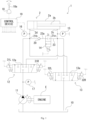
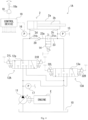
- the hydraulic actuator is, for example, a hydraulic cylinder 2 such as that illustrated in Fig. 1 .
- the hydraulic cylinder 2 can expand and contract to move various elements. More specifically, in the hydraulic cylinder 2, a rod 2b is inserted into a cylinder tube 2a so as to be able to move back and forth. Furthermore, a rod-end port 2c and a head-end port 2d are formed on the cylinder tube 2a. When a working fluid is supplied to and drained from the ports 2c, 2d, the rod 2b moves back and forth with respect to the cylinder tube 2a, in other words, the hydraulic cylinder 2 expands and contracts.
- the hydraulic drive system 1 supplies and drains the working fluid to and from the hydraulic cylinder 2.
- the hydraulic drive system 1 is connected to the ports 2c, 2d of the hydraulic cylinder 2.
- the hydraulic cylinder 2 is retracted.
- the hydraulic drive system 1 when the working fluid is supplied to the head-end port 2d of the hydraulic cylinder 2 and the working fluid is drained from the rod-end port 2c, the hydraulic cylinder 2 is retracted.
- the hydraulic drive system 1 includes a hydraulic pump 11, a meter-in control valve 12, a meter-out control valve 13, a regeneration valve 14, three pressure sensors 15 to 17, an operation device 18, and a control device 19, for example.
- the hydraulic pump 11 is rotationally driven to discharge the working fluid.
- the drive source is an engine E or an electric motor. Note that in the present embodiment, the drive source is the engine E.
- the hydraulic pump 11 is rotationally driven by the engine E to discharge the working fluid.
- the hydraulic pump 11 is a swash plate pump or an axial piston pump.
- the meter-in control valve 12 is located between the hydraulic pump 11 and the hydraulic cylinder 2. Specifically, the meter-in control valve 12 is connected to the hydraulic pump 11 and the ports 2c, 2d of the hydraulic cylinder 2. In the present embodiment, the meter-in control valve 12 is connected to the rod-end port 2c through a rod-end passage 21a and is connected to the head-end port 2d through a head-end passage 21b. Furthermore, the meter-in control valve 12 can control, according to a meter-in command that is input thereto, the direction and the flow rate of the working fluid that is supplied from the hydraulic pump 11 to the hydraulic cylinder 2.
- the meter-in control valve 12 can supply the working fluid from the hydraulic pump 11 to one of the ports 2c, 2d of the hydraulic cylinder 2 and control a meter-in flow rate which is the flow rate of the working fluid being supplied.
- the meter-in control valve 12 is an electronically controlled spool valve. More specifically, the meter-in control valve 12 includes a spool 12a and two electromagnetic proportional control valves 31L, 31R. The spool 12a can switch the flow direction of the working oil by moving, and can further control the opening degree of the meter-in control valve 12.
- the two electromagnetic proportional control valves 31L, 31R can apply pilot pressures directed opposite to each other to the spool 12a.
- the two electromagnetic proportional control valves 31L, 31R output pilot pressures corresponding to a meter-in command that is input thereto, and move spool 12a to a position corresponding to the difference between the two pilot pressures.
- the two electromagnetic proportional control valves 31L, 31R move the spool 12a to a position corresponding to the meter-in command that is input to the two electromagnetic proportional control valves 31L, 31R. Accordingly, the working fluid is supplied to the hydraulic cylinder 2 at a meter-in flow rate in a direction corresponding to the input meter-in command.
- the meter-out control valve 13 is located between the hydraulic pump 11 and the tank 10. Specifically, the meter-out control valve 13 is connected to the ports 2c, 2d of the hydraulic cylinder 2 and the tank 10. In the present embodiment, the meter-out control valve 13 is connected to each of the rod-end passage 21a and the head-end passage 21b in parallel with the meter-in control valve 12. The meter-out control valve 13 can control, according to a meter-out command that is input thereto, the direction and the flow rate (meter-out flow rate) of the working fluid being drained from the hydraulic cylinder 2 into the tank 10.
- the meter-out control valve 13 can switch the direction of the working fluid being drained, to one of the directions from the ports 2c, 2d of the hydraulic cylinder 2 to the tank 10, and control the meter-out flow rate.
- the meter-out control valve 13 can control the flow rate of the working fluid flowing through the meter-out control valve 13, independently of the flow rate of the working fluid being supplied to the hydraulic cylinder 2 via the meter-in control valve 12.
- the meter-out control valve 13 is an electronically controlled spool valve. More specifically, the meter-out control valve 13 includes a spool 13a and two electromagnetic proportional control valves 32L, 32R. The spool 13a can switch the flow direction of the working oil by moving, and can further control the opening degree of the meter-out control valve 13.
- the two electromagnetic proportional control valves 32L, 32R can apply pilot pressures directed opposite to each other to the spool 13a.
- the two electromagnetic proportional control valves 32L, 32R output pilot pressures corresponding to a meter-out command that is input thereto, and move spool 13a to a position corresponding to the difference between the two pilot pressures.
- the two electromagnetic proportional control valves 32L, 32R move the spool 13a to a position corresponding to the meter-out command that is input to the two electromagnetic proportional control valves 32L, 32R. Accordingly, the working fluid is drained from the hydraulic cylinder 2 in a direction corresponding to the input meter-out command at a flow rate corresponding to the input meter-out command.
- the regeneration valve 14 is connected to the hydraulic cylinder 2 in parallel with the meter-out control valve 13.
- the regeneration valve 14 regenerates, to the hydraulic cylinder 2, the working fluid drained from the hydraulic cylinder 2.
- the regeneration valve 14 is located in a regeneration passage 23 connecting the rod-end passage 21a and the head-end passage 21b. More specifically, the regeneration valve 14 is capable of opening and closing the regeneration passage 23 according to a regeneration valve command that is input to the regeneration valve 14.
- a check valve 20 is located in the regeneration passage 23. In the present embodiment, the check valve 20 is located in the regeneration passage 23, on the head-end passage 21b side relative to the regeneration valve 14.
- the check valve 20 allows the working fluid to flow forward in the regeneration passage 23 from the rod-end port 2c to the head-end port 2d, and blocks the opposite flow of the working fluid. Therefore, the hydraulic drive system 1 can regenerate the working fluid from the rod-end port 2c to the head-end port 2d. Furthermore, the regeneration valve 14 can adjust the opening degree according to the regeneration valve command that is input thereto. Thus, the regeneration valve 14 can regenerate the working fluid to the hydraulic cylinder 2 at a regeneration flow rate corresponding to the regeneration valve command that is input to the regeneration valve 14. Note that the regeneration valve 14 can control the flow rate of the working fluid flowing through the regeneration valve 14, independently of the flow rate of the working fluid flowing through each of the meter-in control valve 12 and the meter-out control valve 13. In the present embodiment, the regeneration valve 14 is an electromagnetic proportional control valve.
- the first and second pressure sensors 15, 16 measure hydraulic pressures of the working fluid that is supplied and drained to and from the rod-end port 2c and the head-end port 2d. More specifically, the first pressure sensor 15 is connected to the rod-end passage 21a. This means that the first pressure sensor 15 measures the hydraulic pressure (rod pressure Pcr) of the working fluid that is supplied to and from the rod-end port 2c. On the other hand, the second pressure sensor 16 is connected to the head-end passage 21b. This means that the second pressure sensor 16 measures the hydraulic pressure (head pressure Pch) of the working fluid that is supplied to and from the head-end port 2d.
- the third pressure sensor 17 measures the hydraulic pressure (discharge pressure) of the working fluid that is discharged from the hydraulic pump 11. The three pressure sensors 15 to 17 output the measured hydraulic pressures to the control device 19.
- the operation device 18 outputs an operation command to the control device 19 in order to actuate the hydraulic cylinder 2.
- the operation device 18 is an operation valve or an electric joystick, for example. More specifically, the operation device 18 includes an operation lever 18a which is one example of the operation tool.
- the operation lever 18a is configured in such a manner that an operator can operate the operation lever 18a.
- the operation device 18 outputs an operation command corresponding to the amount of operation of the operation lever 18a to the control device 19.
- the operation lever 18a is configured so as to be able to swing.
- the operation device 18 outputs an operation command corresponding to the amount of swing of the operation lever 18a to the control device 19.
- the control device 19 is connected to the regeneration valve 14, the three pressure sensors 15 to 17, the four electromagnetic proportional control valves 31L, 31R, 32L, 32R, and the operation device 18.
- the control device 19 controls the opening of each of the regeneration valve 14 and the meter-out control valve 13.
- the control device 19 causes the working fluid to be drained from the hydraulic cylinder 2 at a drainage flow rate corresponding to an operation signal from the operation device 18. More specifically, by controlling the opening of the regeneration valve 14 according to the load state of the hydraulic cylinder 2, the control device 19 causes the working fluid to be regenerated from the rod-end port 2c to the head-end port 2d via the regeneration valve 14 at the regeneration flow rate.
- the control device 19 causes the working fluid to be drained from the meter-out control valve 13 into the tank 10 at a meter-out flow rate obtained by subtracting the regeneration flow rate from the drainage flow rate.
- the control device 19 includes a target drainage flow rate calculator 41, a regeneration ratio calculator 42, a pipe pressure estimator 43, and a regeneration valve opening calculator 44, as shown in Fig. 2 , in order to control the opening degree of the regeneration valve 14.
- the control device 19 includes a target drainage flow rate calculator 41, a regeneration flow rate estimator 45, and a meter-in control valve opening calculator (M/O control valve opening calculator) 46, as shown in Fig. 3 , in order to adjust the meter-out flow rate according to the regeneration flow rate.
- M/O control valve opening calculator meter-in control valve opening calculator
- the target drainage flow rate calculator 41 calculates a target drainage flow rate of the working fluid that is drained from the hydraulic cylinder 2 according to the operation command from the operation device 18. In the present embodiment, the target drainage flow rate calculator 41 calculates a target drainage flow rate on the basis of a map indicating the association between operation commands and target drainage flow rates. Note that the target drainage flow rate may be calculated on the basis of a relational expression.
- the regeneration ratio calculator 42 calculates a regeneration ratio on the basis of the load state of the hydraulic cylinder 2.
- the regeneration ratio is the ratio of the regeneration flow rate to the target drainage flow rate of the working fluid that is drained from the hydraulic cylinder 2.
- the regeneration ratio is the ratio of the flow rate of the working fluid to be regenerated relative to the target drainage flow rate of the working fluid that is drained from the hydraulic cylinder 2.
- the load state indicates a load (driving force or braking force) on the hydraulic cylinder 2.
- the load state is calculated using at least one of the hydraulic pressure at the rod-end port 2c (the rod pressure Per measured by the first pressure sensor 15) and the hydraulic pressure at the head-end port 2d (the head pressure Pch measured by the second pressure sensor 16).
- the discharge pressure (the discharge pressure measured by the third pressure sensor 17) may be used instead of the hydraulic pressure at the head-end port 2d.
- the regeneration ratio is set according to the rod pressure Per measured by the first pressure sensor 15 and the head pressure Pch measured by the second pressure sensor 16. In the present embodiment, the regeneration ratio is set low when the head pressure Pch is high and is set high when the head pressure Pch is low. Note that the regeneration ratio is set according to the load on the hydraulic cylinder 2 that is calculated on the basis of the difference between the rod pressure Per and the head pressure Pch. The load on the hydraulic cylinder 2 has a negative value when the rod 2b is extended as a result of being pushed by the load.
- the regeneration ratio is reduced as the absolute value of the load increases in order to extend the rod 2b.
- the relationship between the regeneration ratio and the load state of the hydraulic cylinder 2 is not limited to the aforementioned relationship.
- the regeneration ratio calculator 42 calculates a regeneration ratio on the basis of the measurement result.
- the pipe pressure estimator 43 estimates a downstream pressure of the regeneration valve 14. Specifically, the pipe pressure estimator 43 estimates the pressure (pipe pressure Ph) of the working fluid flowing through a pipe portion 23a located between the regeneration valve 14 and the check valve 20 in the regeneration passage 23. More specifically, pipe pressure estimator 43 estimates the downstream pressure on the basis of the rod pressure Per (drainage pressure) measured by the first pressure sensor 15, the head pressure Pch (supply pressure) measured by the second pressure sensor 16, and a target regeneration opening degree.
- the target regeneration opening degree is the target regeneration opening degree of the regeneration valve 14 calculated by the regeneration valve opening calculator 44, which will be described in detail later.
- the pipe pressure estimator 43 estimates the pipe pressure Ph on the basis of the rod pressure Pcr, the head pressure Pch, the target regeneration opening degree, and the opening degree (predetermined value) of the check valve 20. Note that at the time of estimating the pipe pressure Ph, the head pressure Pch does not necessarily need to be referred to.
- the pipe pressure Ph can be estimated with improved accuracy when the head pressure Pch is additionally referred to.
- the regeneration valve opening calculator 44 calculates a regeneration valve command on the basis of the target drainage flow rate, the regeneration ratio, the head pressure Pch, and the rod pressure Pcr. More specifically, the regeneration valve opening calculator 44 multiplies the target flow rate calculated by the target drainage flow rate calculator 41 by the regeneration ratio calculated by the regeneration ratio calculator 42. Thus, the target regeneration flow rate for the regeneration valve 14 is calculated.
- the regeneration valve opening calculator 44 calculates the target regeneration opening degree on the basis of the calculated target regeneration flow rate, the pipe pressure Ph, and the rod pressure Per measured by the first pressure sensor 15.
- the target regeneration opening degree is the opening degree of the regeneration valve 14 that is applied in order to cause the working fluid to flow to the head-end port 2d at the aforementioned target regeneration flow rate.
- the regeneration valve opening calculator 44 calculates the target regeneration opening degree
- the regeneration valve opening calculator 44 outputs a regeneration valve command corresponding to the target regeneration opening degree to the regeneration valve 14.
- the regeneration flow rate estimator 45 estimates the regeneration flow rate on the basis of the opening degree of the regeneration valve 14. More specifically, the regeneration flow rate estimator 45 estimates the regeneration flow rate on the basis of the target regeneration opening degree and an upstream-downstream pressure difference of the regeneration valve 14. The upstream-downstream pressure difference of the regeneration valve 14 is calculated by subtracting the pipe pressure Ph from the rod pressure Per in the present embodiment.
- the first pressure sensor 15 measures the rod pressure Pcr.
- the pipe pressure estimator 43 estimates the pipe pressure Ph.
- the regeneration valve opening calculator 44 calculates the target regeneration opening degree.
- the M/O control valve opening calculator 46 calculates the target meter-out flow rate. More specifically, the M/O control valve opening calculator 46 calculates the target meter-out flow rate by subtracting the regeneration flow rate from the target drainage flow rate.
- the target drainage flow rate calculator 41 calculates the target drainage flow rate.
- the regeneration flow rate estimator 45 calculates the regeneration flow rate.
- the M/O control valve opening calculator 46 calculates a target meter-out opening degree on the basis of the calculated target meter-out flow rate, the rod pressure Per measured by the first pressure sensor 15, and a predetermined tank pressure.
- the target meter-out opening degree is the opening degree of the meter-out control valve 13 that is to be applied in order to drain the working fluid into the tank 10 at the target meter-out flow rate.
- the target meter-out opening degree may be calculated on the basis of the downstream pressure of the meter-out control valve 13 instead of the tank pressure.
- the downstream pressure of the meter-out control valve 13 is measured by a pressure sensor not illustrated in the drawings or is estimated by a pressure estimating equation.
- the M/O control valve opening calculator 46 calculates the target meter-out opening degree
- the M/O control valve opening calculator 46 outputs a meter-out control valve command (M/O control valve command) corresponding to the target meter-out opening degree to the electromagnetic proportional control valves 32L, 32R.
- the control device 19 outputs a M/O command to the electromagnetic proportional control valve 32L.
- the working fluid is drained into the tank 10 via the meter-out control valve 13 at the target meter-out flow rate.
- the working fluid can be drained from the hydraulic cylinder 2 at the target drainage flow rate using the regeneration valve 14 and the meter-out control valve 13.
- control device 19 controls the opening degree of the meter-in control valve 12 according to the operation command from the operation device 18. More specifically, the control device 19 calculates, on the basis of the operation command from the operation device 18, a target supply flow rate and a direction in which the working oil is supplied. Moreover, the control device 19 calculates a target meter-in flow rate by subtracting the aforementioned target regeneration flow rate from the calculated target supply flow rate.
- the target meter-in flow rate is a flow rate at which the working fluid is to be supplied to the hydraulic cylinder 2 via the meter-in control valve 12.
- control device 19 calculates the opening degree of the meter-in control valve 12 on the basis of the target meter-in flow rate and the upstream-downstream pressure difference of the meter-in control valve 12.
- the control device 19 calculates the upstream-downstream pressure difference of the meter-in control valve 12 on the basis of the hydraulic pressures measured by the third pressure sensor 17 and one of the first and second pressure sensors 15, 16.
- the control device 19 outputs the meter-in control valve command (M/I control valve command) corresponding to the calculated opening degree to the electromagnetic proportional control valves 31L, 31R.
- M/I control valve command corresponding to the calculated opening degree to the electromagnetic proportional control valves 31L, 31R.
- the control device 19 outputs a M/I command to the electromagnetic proportional control valve 31L.
- the working fluid is supplied from the meter-in control valve 12 to the hydraulic cylinder 2 at the target meter-in flow rate.
- the working fluid is supplied to the hydraulic cylinder 2 at the target supply flow rate.
- the working fluid can be regenerated from the rod-end port 2c to the head-end port 2d.
- the control device 19 controls the opening of each of the meter-in control valve 12, the regeneration valve 14, and the meter-out control valve 13 at the time of regeneration as follows. Specifically, when the operation lever 18a is operated, the operation device 18 outputs an operation command corresponding to the amount of operation of the operation lever 18a to the control device 19. The control device 19 then outputs the regeneration valve command to the regeneration valve 14.
- the target drainage flow rate calculator 41 calculates the target drainage flow rate
- the regeneration ratio calculator 42 calculates the regeneration ratio
- the pipe pressure estimator 43 estimates the pipe pressure Ph in the control device 19.
- the regeneration valve opening calculator 44 calculates the target regeneration opening degree on the basis of the target drainage flow rate, the regeneration ratio, and the pipe pressure Ph. Subsequently, in the control device 19, the regeneration valve opening calculator 44 outputs the regeneration valve command corresponding to the target regeneration opening degree to the regeneration valve 14.
- the working fluid is regenerated from the rod-end port 2c to the head-end port 2d at the regeneration flow rate corresponding to the load state of the hydraulic cylinder 2.
- the regeneration flow rate estimator 45 estimates the regeneration flow rate in order to control the opening of the meter-out control valve 13.
- the M/O control valve opening calculator 46 calculates the target meter-out opening degree on the basis of the target drainage flow rate and the regeneration flow rate. Subsequently, in the control device 19, the M/O control valve opening calculator 46 outputs the M/O control valve command corresponding to the target meter-out opening degree to the electromagnetic proportional control valve 32L.
- the working fluid can be drained from the rod-end port 2c of the hydraulic cylinder 2 into the tank 10 via the meter-in control valve 12 at the target meter-out flow rate.
- the target meter-out flow rate and the target regeneration flow rate it is possible to drain the working fluid from the rod-end port 2c at the target drainage flow rate.
- the control device 19 outputs the M/I command corresponding to the operation command and the regeneration flow rate to the electromagnetic proportional control valve 31L.
- the opening of the meter-in control valve 12 is controlled according to the operation command and the regeneration flow rate.
- the working fluid is supplied from the hydraulic pump 11 to the head-end port 2d of the hydraulic cylinder 2 via the meter-in control valve 12 at the target meter-in flow rate.
- the target meter-in flow rate and the target regeneration flow rate it is possible to supply the working fluid to the head-end port 2d at the target supply flow rate.
- the working fluid can be accurately drained from the rod-end port 2c at the target drainage flow rate corresponding to the operation command while the regeneration is carried out from the rod-end port 2c to the head-end port 2d. Therefore, the hydraulic cylinder 2 can operate at the speed corresponding to the amount of operation of the operation lever 18a of the operation device 18. This makes it possible to improve the operability of the hydraulic cylinder 2.
- the hydraulic drive system 1 can independently control the flow rate of the working fluid flowing through each of the meter-in control valve 12, the meter-out control valve 13, and the regeneration valve 14. Therefore, the meter-out flow rate can be adjusted in line with variations in the regeneration flow rate.
- the hydraulic drive system 1 can independently control the flow rate of the working fluid flowing through each of the meter-in control valve 12, the meter-out control valve 13, and the regeneration valve 14. Therefore, the meter-out flow rate can be adjusted in line with variations in the regeneration flow rate.
- the meter-out control valve 13 is connected to the hydraulic actuator in parallel with the regeneration valve 14. Therefore, the working fluid that is drained into the tank 10 is drained from the hydraulic cylinder 2 into the tank 10 without passing through the regeneration valve 14. Thus, it is possible to reduce the pressure loss in the working fluid that is drained into the tank 10. This makes it possible to improve the fuel consumption of the drive source (engine E).
- the hydraulic drive system 1 can maintain, at the flow rate corresponding to the operation signal, the drainage flow rate of the working fluid flowing from the hydraulic cylinder 2. This enables stable operability while maintaining the responsiveness of the hydraulic cylinder 2 as a result of the regeneration flow rate being adjusted to the optimal flow rate.
- the control device 19 calculates the meter-out flow rate by subtracting the target regeneration flow rate from the target drainage flow rate. Therefore, the meter-out flow rate increases or decreases according to variations in the regeneration flow rate, meaning that the regeneration flow rate and the meter-out flow rate can be kept from falling short, for example. Thus, an increase in the discharge pressure of the hydraulic pump 11 and the occurrence of cavitation can be minimized.
- the regeneration valve 14 and the meter-out control valve 13 are arranged in parallel, and thus the pipe pressure Ph can be accurately estimated. This makes it possible to not only improve the accuracy of estimating the regeneration flow rate, but also stabilize the control. Moreover, when the supply pressure measured in order to estimate the pipe pressure Ph is referred to, the pipe pressure Ph can be estimated with improved accuracy. This makes it possible to not only further improve the accuracy of estimating the regeneration flow rate, but also further stabilize the control.
- the hydraulic cylinder 2 is exemplified as the hydraulic actuator to be driven; however, the hydraulic actuator may be a hydraulic motor.
- the hydraulic cylinder 2 is not limited to a single-rod double-acting cylinder and may be a double-rod cylinder or a single-acting cylinder.
- the meter-in control valve 12, the meter-out control valve 13, and the regeneration valve 14 are not limited to having the configurations described above. Specifically, it is sufficient that each of the meter-in control valve 12, the meter-out control valve 13, and the regeneration valve 14 have a controllable opening.
- the spools 12a, 13a of the meter-in control valve 12 and the meter-out control valve 13 may each be driven using an electric motor or the like.
- the number of hydraulic actuators connected to the hydraulic pump 11 may be two or more.
- the operation device 18 includes a plurality of operation levers 18a that are in one-to-one correspondence with hydraulic actuators. When at least two operation levers 18a included in the plurality of operation levers 18a are operated, the control device 19 modifies the target drainage flow rate and the target supply flow rate according to the number of operation levers 18a being operated and the amount of operation of each of the operation levers 18a being operated.
- the regeneration ratio varies according to the load state of the hydraulic cylinder 2, but the regeneration ratio may be a constant value. Alternatively, regarding the regeneration ratio, the regeneration may switch between ON and OFF according to the load state of the hydraulic cylinder 2. Furthermore, in the hydraulic drive system 1 according to the present embodiment, the control device 19 does not necessarily need to control the opening of each of the meter-in control valve 12, the meter-out control valve 13, and the regeneration valve 14 in the above-described manner.
- a hydraulic drive system 1A may be configured as illustrated in Fig. 4 .
- the hydraulic drive system 1A includes a head-end control valve 12A and a rod-end control valve 13A.
- the head-end control valve 12A has a head-end port 2d connected to one of the hydraulic pump 11 and the tank 10.
- the head-end control valve 12A controls the meter-in flow rate and the meter-out flow rate of the working fluid flowing to and from the head-end port 2d.
- the rod-end control valve 13A has a rod-end port 2c connected to one of the hydraulic pump 11 and the tank 10.
- the rod-end control valve 13A controls the meter-in flow rate and the meter-out flow rate of the working fluid flowing to and from the rod-end port 2c. Therefore, in the hydraulic drive system 1A, for example, at the time of extending the rod 2b, the head-end control valve 12A functions as a meter-in control valve, and the rod-end control valve 13A functions as a meter-out control valve.
- the hydraulic drive system 1A has substantially the same configuration as does the hydraulic drive system 1 according to the present embodiment.
- the hydraulic drive system 1A configured as described above can also independently control the flow rate of the working fluid flowing through each of the head-end control valve 12A, the rod-end control valve 13A, and the regeneration valve 14. Therefore, the meter-out flow rate can be adjusted in line with variations in the regeneration flow rate. Thus, it is possible to reduce variations in the drainage flow rate of the working fluid flowing from the hydraulic cylinder 2, and it is possible to reduce the impact of variations in the regeneration flow rate on the responsiveness of the hydraulic actuator.
- the hydraulic drive system 1A produces substantially the same advantageous effects as does the hydraulic drive system 1 according to the present embodiment.
Landscapes
- Engineering & Computer Science (AREA)
- General Engineering & Computer Science (AREA)
- Physics & Mathematics (AREA)
- Fluid Mechanics (AREA)
- Mechanical Engineering (AREA)
- Mining & Mineral Resources (AREA)
- Civil Engineering (AREA)
- Structural Engineering (AREA)
- Fluid-Pressure Circuits (AREA)
- Operation Control Of Excavators (AREA)
Applications Claiming Priority (2)
| Application Number | Priority Date | Filing Date | Title |
|---|---|---|---|
| JP2020106204A JP7523259B2 (ja) | 2020-06-19 | 2020-06-19 | 液圧駆動システム |
| PCT/JP2021/016850 WO2021256098A1 (ja) | 2020-06-19 | 2021-04-27 | 液圧駆動システム |
Publications (2)
| Publication Number | Publication Date |
|---|---|
| EP4170187A1 true EP4170187A1 (de) | 2023-04-26 |
| EP4170187A4 EP4170187A4 (de) | 2024-07-24 |
Family
ID=79244172
Family Applications (1)
| Application Number | Title | Priority Date | Filing Date |
|---|---|---|---|
| EP21825891.1A Pending EP4170187A4 (de) | 2020-06-19 | 2021-04-27 | Hydraulisches antriebssystem |
Country Status (5)
| Country | Link |
|---|---|
| US (1) | US12352293B2 (de) |
| EP (1) | EP4170187A4 (de) |
| JP (1) | JP7523259B2 (de) |
| CN (1) | CN115667732A (de) |
| WO (1) | WO2021256098A1 (de) |
Families Citing this family (8)
| Publication number | Priority date | Publication date | Assignee | Title |
|---|---|---|---|---|
| JP7269436B2 (ja) * | 2020-03-30 | 2023-05-08 | 日立建機株式会社 | 作業機械 |
| WO2023132320A1 (ja) | 2022-01-07 | 2023-07-13 | 凸版印刷株式会社 | 非接触通信媒体 |
| EP4375516A4 (de) * | 2022-01-25 | 2025-07-30 | Hitachi Construction Mach Co | Arbeitsmaschine |
| JP7847487B2 (ja) * | 2022-06-23 | 2026-04-17 | 川崎重工業株式会社 | 液圧駆動装置 |
| JP7847485B2 (ja) * | 2022-06-23 | 2026-04-17 | 川崎重工業株式会社 | 液圧駆動装置 |
| JP2024113468A (ja) * | 2023-02-09 | 2024-08-22 | 株式会社神戸製鋼所 | 作業機械の再生制御装置 |
| WO2026058497A1 (ja) * | 2024-09-13 | 2026-03-19 | 川崎重工業株式会社 | 作業機械の液圧システム |
| WO2026069979A1 (ja) * | 2024-09-27 | 2026-04-02 | 株式会社小松製作所 | 作業機械 |
Family Cites Families (26)
| Publication number | Priority date | Publication date | Assignee | Title |
|---|---|---|---|---|
| DE3710028A1 (de) * | 1987-03-27 | 1988-10-06 | Delmag Maschinenfabrik | Druckmittelbetriebene antriebseinrichtung |
| JP3198163B2 (ja) * | 1992-09-07 | 2001-08-13 | 日立建機株式会社 | 建設機械の油圧駆動装置 |
| JPH11303814A (ja) * | 1998-04-22 | 1999-11-02 | Komatsu Ltd | 圧油供給装置 |
| JP2004092247A (ja) * | 2002-09-02 | 2004-03-25 | Hitachi Constr Mach Co Ltd | 建設機械の油圧駆動装置 |
| US7905088B2 (en) * | 2006-11-14 | 2011-03-15 | Incova Technologies, Inc. | Energy recovery and reuse techniques for a hydraulic system |
| JP5013452B2 (ja) * | 2007-03-06 | 2012-08-29 | キャタピラー エス エー アール エル | 建設機械における油圧制御回路 |
| US7913491B2 (en) * | 2007-11-30 | 2011-03-29 | Caterpillar Inc. | Hydraulic flow control system and method |
| JP2010286074A (ja) * | 2009-06-12 | 2010-12-24 | Kobe Steel Ltd | 作業機械の油圧制御装置及びこれを備えた作業機械 |
| JP2014074433A (ja) * | 2012-10-03 | 2014-04-24 | Sumitomo Heavy Ind Ltd | 建設機械の油圧回路 |
| JP6293527B2 (ja) * | 2014-03-12 | 2018-03-14 | Kyb株式会社 | 制御バルブ装置 |
| CN106460888B (zh) * | 2014-05-19 | 2019-05-10 | 住友重机械工业株式会社 | 挖土机及其控制方法 |
| JP6317656B2 (ja) * | 2014-10-02 | 2018-04-25 | 日立建機株式会社 | 作業機械の油圧駆動システム |
| JP6621130B2 (ja) * | 2015-02-06 | 2019-12-18 | キャタピラー エス エー アール エル | 油圧アクチュエータ制御回路 |
| US10174770B2 (en) | 2015-11-09 | 2019-01-08 | Caterpillar Inc. | System and method of hydraulic energy recovery for machine start-stop and machine ride control |
| KR102510852B1 (ko) * | 2015-12-04 | 2023-03-16 | 현대두산인프라코어 주식회사 | 건설기계의 유압 시스템 및 유압 제어 방법 |
| JP6591370B2 (ja) | 2016-08-18 | 2019-10-16 | 日立建機株式会社 | 建設機械の油圧制御装置 |
| US10337532B2 (en) * | 2016-12-02 | 2019-07-02 | Caterpillar Inc. | Split spool valve |
| US10988915B2 (en) * | 2017-04-10 | 2021-04-27 | Doosan Infracore Co., Ltd. | Hydraulic system of construction machinery |
| JP6845736B2 (ja) * | 2017-04-28 | 2021-03-24 | 川崎重工業株式会社 | 液圧駆動システム |
| US10428845B1 (en) * | 2018-03-29 | 2019-10-01 | Sun Hydraulics, Llc | Hydraulic system with a counterbalance valve configured as a meter-out valve and controlled by an independent pilot signal |
| JP2019199881A (ja) | 2018-05-14 | 2019-11-21 | 株式会社神戸製鋼所 | 作業機械の油圧駆動装置 |
| EP3856981B1 (de) * | 2018-09-27 | 2025-12-17 | Volvo Construction Equipment AB | Regenerationssystem und verfahren zur energiefreisetzung aus einem arbeitsgerät |
| KR102633378B1 (ko) * | 2019-02-13 | 2024-02-02 | 에이치디현대인프라코어 주식회사 | 건설 기계 |
| JP7382792B2 (ja) * | 2019-10-31 | 2023-11-17 | 川崎重工業株式会社 | 再生装置、それを備える液圧駆動システム、及びその制御装置 |
| US12018458B2 (en) * | 2020-06-17 | 2024-06-25 | Hitachi Construction Machinery Co., Ltd. | Construction machine |
| JP7653774B2 (ja) * | 2020-07-14 | 2025-03-31 | 川崎重工業株式会社 | 液圧駆動システム |
-
2020
- 2020-06-19 JP JP2020106204A patent/JP7523259B2/ja active Active
-
2021
- 2021-04-27 EP EP21825891.1A patent/EP4170187A4/de active Pending
- 2021-04-27 US US18/001,650 patent/US12352293B2/en active Active
- 2021-04-27 CN CN202180040425.3A patent/CN115667732A/zh active Pending
- 2021-04-27 WO PCT/JP2021/016850 patent/WO2021256098A1/ja not_active Ceased
Also Published As
| Publication number | Publication date |
|---|---|
| US12352293B2 (en) | 2025-07-08 |
| CN115667732A (zh) | 2023-01-31 |
| EP4170187A4 (de) | 2024-07-24 |
| WO2021256098A1 (ja) | 2021-12-23 |
| US20250116280A1 (en) | 2025-04-10 |
| US20230235755A1 (en) | 2023-07-27 |
| JP2022001769A (ja) | 2022-01-06 |
| JP7523259B2 (ja) | 2024-07-26 |
Similar Documents
| Publication | Publication Date | Title |
|---|---|---|
| US12352293B2 (en) | Hydraulic drive system | |
| EP3158205B1 (de) | Verfahren zur steuerung der geschwindigkeit eines hydraulischen stellantrieb in systemen mit richtungswechsel der belastungen | |
| JP4791789B2 (ja) | 電子作動及び液圧作動されるドレン弁 | |
| JP6621130B2 (ja) | 油圧アクチュエータ制御回路 | |
| CN106762909B (zh) | 一种高速开关阀先导控制的液压多路阀及其控制方法 | |
| US10494791B2 (en) | Flow control valve for construction machine | |
| KR102561435B1 (ko) | 건설기계의 제어 시스템 및 건설기계의 제어 방법 | |
| JP5184773B2 (ja) | 圧力補償弁を有する油圧システム | |
| JP7404258B2 (ja) | 流体回路 | |
| JP2022001769A5 (de) | ||
| JP2017115992A (ja) | 作業機の油圧システム | |
| US11815109B2 (en) | Regeneration device, hydraulic drive system equipped with same, and control device therefor | |
| EP3795844B1 (de) | Baumaschine | |
| JP2017015130A (ja) | 流体回路 | |
| US20170108015A1 (en) | Independent Metering Valves with Flow Sharing | |
| JP2011517754A (ja) | 方向制御弁の制御装置 | |
| US12055162B2 (en) | Hydraulic drive system | |
| US12618421B2 (en) | Hydraulic drive system | |
| KR20150122185A (ko) | 작업 기계용 압력 손실 저감 회로 | |
| US20250188710A1 (en) | Hydraulic drive apparatus | |
| US12196230B2 (en) | Control device and hydraulic system including the same | |
| US20120205563A1 (en) | Valve arrangement for actuating a load | |
| CN222415454U (zh) | 阀杆组件、液压控制阀、液压控制系统及作业设备 | |
| JPH048903A (ja) | 多機能弁 | |
| JP7803822B2 (ja) | 液圧駆動システム |
Legal Events
| Date | Code | Title | Description |
|---|---|---|---|
| STAA | Information on the status of an ep patent application or granted ep patent |
Free format text: STATUS: THE INTERNATIONAL PUBLICATION HAS BEEN MADE |
|
| PUAI | Public reference made under article 153(3) epc to a published international application that has entered the european phase |
Free format text: ORIGINAL CODE: 0009012 |
|
| STAA | Information on the status of an ep patent application or granted ep patent |
Free format text: STATUS: REQUEST FOR EXAMINATION WAS MADE |
|
| 17P | Request for examination filed |
Effective date: 20230119 |
|
| AK | Designated contracting states |
Kind code of ref document: A1 Designated state(s): AL AT BE BG CH CY CZ DE DK EE ES FI FR GB GR HR HU IE IS IT LI LT LU LV MC MK MT NL NO PL PT RO RS SE SI SK SM TR |
|
| DAV | Request for validation of the european patent (deleted) | ||
| DAX | Request for extension of the european patent (deleted) | ||
| A4 | Supplementary search report drawn up and despatched |
Effective date: 20240621 |
|
| RIC1 | Information provided on ipc code assigned before grant |
Ipc: F15B 11/042 20060101ALI20240617BHEP Ipc: F15B 11/044 20060101ALI20240617BHEP Ipc: F15B 11/028 20060101ALI20240617BHEP Ipc: E02F 9/22 20060101ALI20240617BHEP Ipc: F15B 11/024 20060101AFI20240617BHEP |