EP4170188B1 - Section d'entrée destinée à être utilisée dans un distributeur hydraulique - Google Patents
Section d'entrée destinée à être utilisée dans un distributeur hydraulique Download PDFInfo
- Publication number
- EP4170188B1 EP4170188B1 EP22196863.9A EP22196863A EP4170188B1 EP 4170188 B1 EP4170188 B1 EP 4170188B1 EP 22196863 A EP22196863 A EP 22196863A EP 4170188 B1 EP4170188 B1 EP 4170188B1
- Authority
- EP
- European Patent Office
- Prior art keywords
- area
- slider
- pressure
- inlet section
- spring
- Prior art date
- Legal status (The legal status is an assumption and is not a legal conclusion. Google has not performed a legal analysis and makes no representation as to the accuracy of the status listed.)
- Active
Links
Images






Classifications
-
- F—MECHANICAL ENGINEERING; LIGHTING; HEATING; WEAPONS; BLASTING
- F15—FLUID-PRESSURE ACTUATORS; HYDRAULICS OR PNEUMATICS IN GENERAL
- F15B—SYSTEMS ACTING BY MEANS OF FLUIDS IN GENERAL; FLUID-PRESSURE ACTUATORS, e.g. SERVOMOTORS; DETAILS OF FLUID-PRESSURE SYSTEMS, NOT OTHERWISE PROVIDED FOR
- F15B11/00—Servomotor systems without provision for follow-up action; Circuits therefor
- F15B11/16—Servomotor systems without provision for follow-up action; Circuits therefor with two or more servomotors
- F15B11/161—Servomotor systems without provision for follow-up action; Circuits therefor with two or more servomotors with sensing of servomotor demand or load
- F15B11/165—Servomotor systems without provision for follow-up action; Circuits therefor with two or more servomotors with sensing of servomotor demand or load for adjusting the pump output or bypass in response to demand
-
- F—MECHANICAL ENGINEERING; LIGHTING; HEATING; WEAPONS; BLASTING
- F16—ENGINEERING ELEMENTS AND UNITS; GENERAL MEASURES FOR PRODUCING AND MAINTAINING EFFECTIVE FUNCTIONING OF MACHINES OR INSTALLATIONS; THERMAL INSULATION IN GENERAL
- F16K—VALVES; TAPS; COCKS; ACTUATING-FLOATS; DEVICES FOR VENTING OR AERATING
- F16K11/00—Multiple-way valves, e.g. mixing valves; Pipe fittings incorporating such valves
- F16K11/02—Multiple-way valves, e.g. mixing valves; Pipe fittings incorporating such valves with all movable sealing faces moving as one unit
- F16K11/06—Multiple-way valves, e.g. mixing valves; Pipe fittings incorporating such valves with all movable sealing faces moving as one unit comprising only sliding valves, i.e. sliding closure elements
- F16K11/065—Multiple-way valves, e.g. mixing valves; Pipe fittings incorporating such valves with all movable sealing faces moving as one unit comprising only sliding valves, i.e. sliding closure elements with linearly sliding closure members
- F16K11/07—Multiple-way valves, e.g. mixing valves; Pipe fittings incorporating such valves with all movable sealing faces moving as one unit comprising only sliding valves, i.e. sliding closure elements with linearly sliding closure members with cylindrical slides
-
- F—MECHANICAL ENGINEERING; LIGHTING; HEATING; WEAPONS; BLASTING
- F15—FLUID-PRESSURE ACTUATORS; HYDRAULICS OR PNEUMATICS IN GENERAL
- F15B—SYSTEMS ACTING BY MEANS OF FLUIDS IN GENERAL; FLUID-PRESSURE ACTUATORS, e.g. SERVOMOTORS; DETAILS OF FLUID-PRESSURE SYSTEMS, NOT OTHERWISE PROVIDED FOR
- F15B13/00—Details of servomotor systems ; Valves for servomotor systems
- F15B13/02—Fluid distribution or supply devices characterised by their adaptation to the control of servomotors
- F15B13/04—Fluid distribution or supply devices characterised by their adaptation to the control of servomotors for use with a single servomotor
- F15B13/0416—Fluid distribution or supply devices characterised by their adaptation to the control of servomotors for use with a single servomotor with means or adapted for load sensing
-
- F—MECHANICAL ENGINEERING; LIGHTING; HEATING; WEAPONS; BLASTING
- F16—ENGINEERING ELEMENTS AND UNITS; GENERAL MEASURES FOR PRODUCING AND MAINTAINING EFFECTIVE FUNCTIONING OF MACHINES OR INSTALLATIONS; THERMAL INSULATION IN GENERAL
- F16K—VALVES; TAPS; COCKS; ACTUATING-FLOATS; DEVICES FOR VENTING OR AERATING
- F16K31/00—Actuating devices; Operating means; Releasing devices
- F16K31/12—Actuating devices; Operating means; Releasing devices actuated by fluid
- F16K31/122—Actuating devices; Operating means; Releasing devices actuated by fluid the fluid acting on a piston
- F16K31/1221—Actuating devices; Operating means; Releasing devices actuated by fluid the fluid acting on a piston one side of the piston being spring-loaded
-
- F—MECHANICAL ENGINEERING; LIGHTING; HEATING; WEAPONS; BLASTING
- F15—FLUID-PRESSURE ACTUATORS; HYDRAULICS OR PNEUMATICS IN GENERAL
- F15B—SYSTEMS ACTING BY MEANS OF FLUIDS IN GENERAL; FLUID-PRESSURE ACTUATORS, e.g. SERVOMOTORS; DETAILS OF FLUID-PRESSURE SYSTEMS, NOT OTHERWISE PROVIDED FOR
- F15B2211/00—Circuits for servomotor systems
- F15B2211/20—Fluid pressure source, e.g. accumulator or variable axial piston pump
- F15B2211/205—Systems with pumps
- F15B2211/2053—Type of pump
- F15B2211/20538—Type of pump constant capacity
-
- F—MECHANICAL ENGINEERING; LIGHTING; HEATING; WEAPONS; BLASTING
- F15—FLUID-PRESSURE ACTUATORS; HYDRAULICS OR PNEUMATICS IN GENERAL
- F15B—SYSTEMS ACTING BY MEANS OF FLUIDS IN GENERAL; FLUID-PRESSURE ACTUATORS, e.g. SERVOMOTORS; DETAILS OF FLUID-PRESSURE SYSTEMS, NOT OTHERWISE PROVIDED FOR
- F15B2211/00—Circuits for servomotor systems
- F15B2211/20—Fluid pressure source, e.g. accumulator or variable axial piston pump
- F15B2211/25—Pressure control functions
- F15B2211/253—Pressure margin control, e.g. pump pressure in relation to load pressure
-
- F—MECHANICAL ENGINEERING; LIGHTING; HEATING; WEAPONS; BLASTING
- F15—FLUID-PRESSURE ACTUATORS; HYDRAULICS OR PNEUMATICS IN GENERAL
- F15B—SYSTEMS ACTING BY MEANS OF FLUIDS IN GENERAL; FLUID-PRESSURE ACTUATORS, e.g. SERVOMOTORS; DETAILS OF FLUID-PRESSURE SYSTEMS, NOT OTHERWISE PROVIDED FOR
- F15B2211/00—Circuits for servomotor systems
- F15B2211/30—Directional control
- F15B2211/305—Directional control characterised by the type of valves
- F15B2211/30525—Directional control valves, e.g. 4/3-directional control valve
- F15B2211/3053—In combination with a pressure compensating valve
- F15B2211/30555—Inlet and outlet of the pressure compensating valve being connected to the directional control valve
-
- F—MECHANICAL ENGINEERING; LIGHTING; HEATING; WEAPONS; BLASTING
- F15—FLUID-PRESSURE ACTUATORS; HYDRAULICS OR PNEUMATICS IN GENERAL
- F15B—SYSTEMS ACTING BY MEANS OF FLUIDS IN GENERAL; FLUID-PRESSURE ACTUATORS, e.g. SERVOMOTORS; DETAILS OF FLUID-PRESSURE SYSTEMS, NOT OTHERWISE PROVIDED FOR
- F15B2211/00—Circuits for servomotor systems
- F15B2211/30—Directional control
- F15B2211/31—Directional control characterised by the positions of the valve element
- F15B2211/3105—Neutral or centre positions
- F15B2211/3111—Neutral or centre positions the pump port being closed in the centre position, e.g. so-called closed centre
-
- F—MECHANICAL ENGINEERING; LIGHTING; HEATING; WEAPONS; BLASTING
- F15—FLUID-PRESSURE ACTUATORS; HYDRAULICS OR PNEUMATICS IN GENERAL
- F15B—SYSTEMS ACTING BY MEANS OF FLUIDS IN GENERAL; FLUID-PRESSURE ACTUATORS, e.g. SERVOMOTORS; DETAILS OF FLUID-PRESSURE SYSTEMS, NOT OTHERWISE PROVIDED FOR
- F15B2211/00—Circuits for servomotor systems
- F15B2211/50—Pressure control
- F15B2211/505—Pressure control characterised by the type of pressure control means
- F15B2211/50509—Pressure control characterised by the type of pressure control means the pressure control means controlling a pressure upstream of the pressure control means
- F15B2211/50536—Pressure control characterised by the type of pressure control means the pressure control means controlling a pressure upstream of the pressure control means using unloading valves controlling the supply pressure by diverting fluid to the return line
-
- F—MECHANICAL ENGINEERING; LIGHTING; HEATING; WEAPONS; BLASTING
- F15—FLUID-PRESSURE ACTUATORS; HYDRAULICS OR PNEUMATICS IN GENERAL
- F15B—SYSTEMS ACTING BY MEANS OF FLUIDS IN GENERAL; FLUID-PRESSURE ACTUATORS, e.g. SERVOMOTORS; DETAILS OF FLUID-PRESSURE SYSTEMS, NOT OTHERWISE PROVIDED FOR
- F15B2211/00—Circuits for servomotor systems
- F15B2211/50—Pressure control
- F15B2211/52—Pressure control characterised by the type of actuation
- F15B2211/528—Pressure control characterised by the type of actuation actuated by fluid pressure
-
- F—MECHANICAL ENGINEERING; LIGHTING; HEATING; WEAPONS; BLASTING
- F15—FLUID-PRESSURE ACTUATORS; HYDRAULICS OR PNEUMATICS IN GENERAL
- F15B—SYSTEMS ACTING BY MEANS OF FLUIDS IN GENERAL; FLUID-PRESSURE ACTUATORS, e.g. SERVOMOTORS; DETAILS OF FLUID-PRESSURE SYSTEMS, NOT OTHERWISE PROVIDED FOR
- F15B2211/00—Circuits for servomotor systems
- F15B2211/50—Pressure control
- F15B2211/57—Control of a differential pressure
Definitions
- the present invention relates to an inlet section for use in a hydraulic distributor.
- control valves which allow to control the flow provided to actuators regardless of their pressures.
- Such valves are commonly referred to as load-sensing direction control valves or load-sensing distributors.
- a load-sensing system allows to keep the pressure drop substantially constant across the variable adjustment notches of a slider for directional valves.
- the delivery of flow to the uses can be considered independent of the load and proportional to the opening of the slider adjustment notches.
- a particular type of load-sensing distributors are flow-sharing systems, which are widely used on movable machines which require simultaneous movements without loss of control in the various operating conditions.
- the flow-sharing (antisaturation) systems add some specific features to the traditional load-sensing systems which allow to solve the problem of the flow saturation and consequent loss of control and simultaneous movement.
- open-centre load-sensing systems in stand-by condition, i.e., when no flow is required by the users, discharge all the flow delivered by the pump.
- a pressure compensator capable of discharging the pump flow in stand-by conditions and which is used to manage the LS pressure margin in operating conditions. If the total flow required by the users is lower than the pump feed rate, the pressure compensator works by discharging the excess flow which is not required by the functions actuated at a pressure value equal to the maximum pressure of the load to the uses (LS pressure) plus a ⁇ p (pressure margin) related to the flow characteristic of the compensator and its settings.
- US 2004/0020196 proposes a piloted compensation mechanism capable of reducing the pressure margin in stand-by conditions.
- the mechanism consists of a main bypass slider, which manages the connection of the pressure line coming from the pump with the discharge, a pilot exchange valve and a decompression valve.
- WO 2007/116035 proposes a piloted-type differential area pressure compensator and its control device.
- the pressure compensator discharges the pump flow at two pressure levels based on how the control system manages the pressure acting on the differential areas of the compensator. All these solutions are characterized by a high complexity and are mainly based on structural changes of the main discharge compensator (with differential areas or double regulation position) and on the integration of second stages at low pressure.
- Another object of the present invention is to propose an inlet section for use in a hydraulic distributor, which allows to reduce the thermal dissipation of the system with respect to the known solutions.
- control spring is mounted so as to have a first abutment on the fourth area of the mechanical thrust means and a second abutment in a recess of the second cap.
- the inlet section comprises an actuator body at least partially inserted in the through hole and comprising:
- the inlet section comprises a three-way, two-position device communicating with the spring chamber to selectively actuate the connection with the low pressure line or with the detection line of the highest load pressure required by the uses.
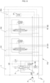
- a hydraulic feeding system typically consists of a fixed displacement pump P and the distributor FS.
- the pump P feeds the distributor FS along a high pressure line HP, which brings the fluid to uses A1, A2, B1, B2; a low pressure line TL connects the distributor FS to a discharge T.
- the distributor FS further comprises a line LS for detecting the highest load pressure required by the uses A1, A2, B1, B2.
- the first and the second pressure are linked to each other by the pressure margin, which nominally corresponds to the difference between the two pressures.
- the operating pressure margin when the compensator is in the working step and thus discharges part of the flow rate or the entire flow rate, this typically varies between 13 bar and 25 bar. As these are usually geared fixed displacement pumps or in extreme cases pistons, the maximum pressures are approximately between 230 bar and 300 bar.
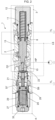
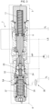
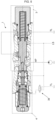
- the inlet section 1 comprises a valve body 2. There are housed within the valve body 2 a discharge compensator 3, which selectively connects the high pressure line HP to the low pressure line TL, and a control device 4 which actuates the pressure margin reduction function by mechanically acting on the dynamic balance of the compensator 3.
- the compensator 3 comprises a slider 6 longitudinally slidable within the valve body 2 between a first position, in which it prevents the passage of fluid from the high pressure line HP to the low pressure line TL, and a second position, in which it enables the passage of the pressurized fluid coming from the high pressure line HP towards the low pressure line TL.
- the second position of the slider 6 is an extreme operating position, in which the passage of fluid at the maximum possible flow rate is allowed.
- a fluid passage 9 is obtained in the body of the slider 6 so as to put the first area S1 in communication with the first conduit 7.
- the first conduit 7 is interposed between the first and the second area S1, S2.
- a front chamber 13 is defined between the first cap 12, the internal walls of the valve body 2 and the slider 6.
- the second active area S2 is located in the front chamber 13 and slides therein.
- the slider 6 In a standard operating condition of the hydraulic distributor FS, with the exception of the flow saturation condition, the slider 6 is in an intermediate position between the first and the second position, in which it discharges the excess flow, not required by the uses A1, A2, B1, B2.
- the piston 26 has a cylinder cup shape. That is, the piston 26 comprises a thrust portion 28 facing the actuator element 18 and a hollow shell portion 29 therein, originating from the thrust portion 28 away therefrom.
- the shell portion 29 comprises an internal abutment surface 30 for an end of the control spring 27.
- the eighth area S4 is obtained from the sum of the extreme circular surface of the shell 29 and the abutment surface 30.
- the main spring 11 and the first cap 12 are arranged at the first open end 5a, as described above.
- a spring chamber 34 is defined between the piston 26, the internal walls of the jacket portion 31 and the second cap 34.
- control device 4 In the presence of an appropriate second pressure value acting on the active areas S6, S7 and the corresponding first pressure acting on the fifth area S3 of the actuator element 18, the control device 4 is deactivated (standard operating condition of the distributor FS). Deactivation of the control device 4 herein means that the mechanical thrust means 17 of the control device 4 is distanced (thus retracted) from the slider 6 and does not act thereon.
- the second pressure is discharged by means of a compensated valve 37 (visible in figures 6a, 6b, 7-11 , in the outlet block PH) and the pump flow is discharged by the compensator 3.
- the discharge pressure would be determined by the features of the main spring 11.
- the compensator 3 is subject to the additional action of the control device 4 through the actuator element 18 since, the second pressure LS being zero, the control spring 27 can mechanically transmit part of its dynamic characteristic to the slider 6 reducing, to maintain the overall dynamic balance, the pressure force HP quota necessary to ensure the discharge of the pump flow. All this translates into an automatic reduction of the pressure margin to non-operating functions.
- the second cap 33 acts as an abutment and stroke end of the mechanical thrust means 17, in particular of the fourth area S4.
- FIG. 8-9 provides a three-way, two-position device 38, acting on the pressure line coming from the spring chamber 34 of the control device 4, which selectively actuates the connection to discharge T or that to the second pressure LS of the spring chamber 34 itself.
- the device 38 is for example a solenoid valve.
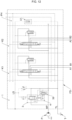
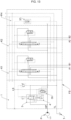
- the three-way, two-position device 38 can be integrated with the distributor FS or be remote in the machine system and can be replaced by its variants as for example in figures 10-12 .
- the device 38 actuates the discharge connection of the spring chamber 34 of the control device 4.
- the maximum antagonistic force at the compensator 3 is made operational even during normal system operation and not only in stand-by conditions. All this translates into a controlled reduction of the pressure margin of the system and consequently a reduction of the flow rates/implementation speeds with slight energy savings due to the lower operating pressure delta.
- the system operates in its "slow" configuration.
- Figure 13 shows an embodiment capable of ensuring a continuous proportional control of the pressure margin.
- the pressure reducer 39 has a first inlet 39a communicating with the high pressure line HP, a second inlet 39b communicating with the detection line LS and an outlet 39c feeding the spring chamber 34.
- Such a pressure reducer 39 is structured to withstand high operating pressures.
- control device in the hole of the compensator already present in standard distributors. It is sufficient to insert the control device, with two closing caps at the two ends of the hole to make the two devices isolated from the outside.
Landscapes
- Engineering & Computer Science (AREA)
- General Engineering & Computer Science (AREA)
- Mechanical Engineering (AREA)
- Physics & Mathematics (AREA)
- Fluid Mechanics (AREA)
- Fluid-Pressure Circuits (AREA)
Claims (10)
- Section d'entrée (1) destinée à être utilisée dans un distributeur hydraulique (FS), comprenant :un corps de soupape (2) ;un coulisseau (6), doté d'une première zone (S1) et d'une deuxième zone (S2) ayant sensiblement les mêmes dimensions et situées à deux extrémités opposées dudit coulisseau (6),ledit coulisseau (6) pouvant coulisser longitudinalement à l'intérieur du corps de soupape (2) entre une première position dans laquelle il empêche le passage du fluide d'une ligne à haute pression (HP) à une ligne à basse pression (TL), et une deuxième position dans laquelle il permet ledit passage de fluide,ladite première zone (S1) étant soumise à l'action d'une première pression alimentée par la ligne à haute pression (HP) et agissant dans une direction telle qu'elle pousse le coulisseau (6) vers la deuxième position, ladite deuxième zone (S2) étant soumise à une deuxième pression alimentée par une ligne (LS) pour détecter la plus haute pression de charge requise par les utilisations (A1, A2, B1, B2) placées en aval du distributeur (FS), ladite deuxième pression agissant dans une direction opposée à ladite première pression et de manière à pousser le coulisseau (6) vers la première position,un ressort principal (11) agissant sur la deuxième zone (S2) du coulisseau (6) dans une direction concordant avec l'action de la deuxième pression ;un dispositif de commande (4) du coulisseau (6) comprenant des moyens de poussée mécaniques (17) sélectivement actifs sur le coulisseau (6) dans une direction concordant avec l'action de la première pression sur la première zone (S1) du coulisseau (6) de manière à forcer le coulisseau (6) dans la deuxième position, lesdits moyens de poussée mécaniques (17) comprenant une troisième zone (S3) et une quatrième zone (S4) étant situées à deux extrémités opposées, ladite troisième zone (S3) faisant face à la première zone (S1) du coulisseau (6) et étant également soumise à la première pression,ledit dispositif de commande (4) comprenant de plus un ressort de commande (27) actif sur la quatrième zone (S4) opposé au ressort principal (11),une chambre à ressort (34) étant définie à l'intérieur dudit corps de soupape (2), dans laquelle la quatrième zone (S4) des moyens de poussée mécaniques (17) et une extrémité du ressort de commande (27) sont situés,un trou traversant (5) obtenu dans le corps de soupape (2), le trou traversant comportant deux extrémités ouvertes (5a, 5b) opposées l'une à l'autre,ledit dispositif de commande (4) étant configurable dans une condition de poussée, dans laquelle la troisième zone (S3) agit sur la première zone (S1) du coulisseau (6) avec la première pression pour le forcer dans sa deuxième position, et dans une condition de désactivation, dans laquelle la troisième zone (S3) est éloignée et rétractée de la première zone (S1) du coulisseau (6),dans laquelle les moyens de poussée mécaniques (17) comprennent :- un élément actionneur (18) coulissant longitudinalement à l'intérieur du trou traversant (5) et sélectivement actif sur la première zone (S1) du coulisseau (6) pour le forcer dans sa deuxième position, ledit élément actionneur (18) comportant une cinquième et une sixième zone (S3, S6) ayant sensiblement la même taille et étant situées à deux extrémités opposées dudit élément actionneur (18), ladite cinquième zone représentant la troisième zone (S3) des moyens de poussée mécaniques (17), ladite sixième zone (S6) étant soumise à l'action de la deuxième pression ;- un piston (26) comportant une septième zone (S7) en contact avec la sixième zone (S6) de l'élément actionneur (18) pour le déplacer vers le coulisseau (6), ladite septième zone (S7) étant également soumise à la deuxième pression, et une huitième zone représentant la quatrième zone (S4) des moyens de poussée mécaniques (17).
- Section d'entrée (1) selon la revendication 1, ladite section d'entrée (1) comprenant un premier bouchon (12) et un deuxième bouchon (33) fermant lesdites deux extrémités ouvertes (5a, 5b), ledit coulisseau (6) et ledit dispositif de commande (4) étant disposés dans le trou traversant (5) entre ledit premier bouchon (12) et ledit deuxième bouchon (33).
- Section d'entrée (1) selon la revendication 2, dans laquelle le ressort principal (11) est monté de manière à comporter une première butée sur la deuxième zone (S2) du coulisseau (6) et une deuxième butée dans un renfoncement du premier bouchon de fermeture (12).
- Section d'entrée (1) selon la revendication 2 ou 3, dans laquelle le ressort de commande (27) du dispositif de commande (4) est monté de manière à comporter une première butée sur la quatrième zone (S4) des moyens de poussée mécaniques (17) et une deuxième butée dans un renfoncement du deuxième bouchon de fermeture (33).
- Section d'entrée (1) selon l'une quelconque des revendications 2 à 4, dans laquelle le trou traversant (5) comporte une extension principale le long d'une direction longitudinale (X-X), ledit coulisseau (6) et lesdits moyens de poussée mécaniques (17) étant disposés dans le trou traversant (5) alignés le long de la direction longitudinale (X-X).
- Section d'entrée (1) selon la revendication 5, dans laquelle le ressort principal (11), le coulisseau (6), les moyens de poussée mécaniques (17) et le ressort de commande (27) agissent le long de la direction longitudinale (X-X).
- Section d'entrée (1) selon l'une quelconque des revendications précédentes, comprenant un corps d'actionneur (19) au moins partiellement inséré dans le trou traversant (5) et comprenant :- une première partie (20) façonnée de manière à comporter un trou traversant (21) dans lequel l'élément actionneur (18) est inséré de manière coulissante, définissant ainsi une chambre intermédiaire (22) entre le coulisseau (6), les parois internes du corps de soupape (2) et le corps actionneur (19), dans laquelle se trouvent ladite première zone (S1) du coulisseau (6) et ladite troisième zone (S3) de l'élément actionneur (18), ladite chambre intermédiaire (22) étant en communication fluidique avec la ligne à haute pression (HP) ;- une deuxième partie (31) en forme de chemise et partant de la première partie (20) en s'éloignant de celle-ci, ladite deuxième partie (31) enveloppant le piston (26), ledit piston (26) étant monté de façon coulissante en son sein.
- Section d'entrée (1) selon la revendication 7, la revendication 7 étant dépendante de la revendication 2, dans laquelle la deuxième partie (31) comporte une extrémité ouverte dans laquelle elle reçoit ledit deuxième bouchon de fermeture (33), définissant ainsi ladite chambre à ressort (34) entre les moyens de poussée mécaniques (17), les parois internes de la deuxième partie (31) et le deuxième bouchon (33).
- Section d'entrée (1) selon l'une quelconque des revendications précédentes, comprenant un dispositif à trois voies et à deux positions (38), agissant sur la chambre à ressort (34) pour actionner sélectivement le raccordement avec la ligne à basse pression (TL) ou avec la ligne de détection (LS) de la pression de charge la plus élevée requise par les utilisations (A1, A2, B1, B2).
- Section d'entrée (1) selon l'une quelconque des revendications 1 à 8, comprenant un détendeur de pression (39) comportant une première entrée (39a) en communication avec la ligne à haute pression (HP), une deuxième entrée (39b) en communication avec la ligne de détection (LS) et une sortie (39c) en communication en aval avec la chambre à ressort (34) de manière à alimenter une pression régulée (Px) ayant une valeur comprise entre celle de la deuxième pression et celle de la première pression.
Priority Applications (1)
| Application Number | Priority Date | Filing Date | Title |
|---|---|---|---|
| EP23188549.2A EP4279750B1 (fr) | 2021-10-21 | 2022-09-21 | Section d'entrée destinée à être utilisée dans un distributeur hydraulique |
Applications Claiming Priority (1)
| Application Number | Priority Date | Filing Date | Title |
|---|---|---|---|
| IT202100027122 | 2021-10-21 |
Related Child Applications (2)
| Application Number | Title | Priority Date | Filing Date |
|---|---|---|---|
| EP23188549.2A Division-Into EP4279750B1 (fr) | 2021-10-21 | 2022-09-21 | Section d'entrée destinée à être utilisée dans un distributeur hydraulique |
| EP23188549.2A Division EP4279750B1 (fr) | 2021-10-21 | 2022-09-21 | Section d'entrée destinée à être utilisée dans un distributeur hydraulique |
Publications (3)
| Publication Number | Publication Date |
|---|---|
| EP4170188A1 EP4170188A1 (fr) | 2023-04-26 |
| EP4170188B1 true EP4170188B1 (fr) | 2024-07-10 |
| EP4170188C0 EP4170188C0 (fr) | 2024-07-10 |
Family
ID=79270123
Family Applications (2)
| Application Number | Title | Priority Date | Filing Date |
|---|---|---|---|
| EP22196863.9A Active EP4170188B1 (fr) | 2021-10-21 | 2022-09-21 | Section d'entrée destinée à être utilisée dans un distributeur hydraulique |
| EP23188549.2A Active EP4279750B1 (fr) | 2021-10-21 | 2022-09-21 | Section d'entrée destinée à être utilisée dans un distributeur hydraulique |
Family Applications After (1)
| Application Number | Title | Priority Date | Filing Date |
|---|---|---|---|
| EP23188549.2A Active EP4279750B1 (fr) | 2021-10-21 | 2022-09-21 | Section d'entrée destinée à être utilisée dans un distributeur hydraulique |
Country Status (2)
| Country | Link |
|---|---|
| US (2) | US11852249B2 (fr) |
| EP (2) | EP4170188B1 (fr) |
Families Citing this family (2)
| Publication number | Priority date | Publication date | Assignee | Title |
|---|---|---|---|---|
| US12442396B2 (en) * | 2020-01-27 | 2025-10-14 | Parker-Hannifin Corporation | Valve with an adjustable flow sharing pressure compensator |
| CN116733995A (zh) * | 2023-05-31 | 2023-09-12 | 辽宁五寰特种材料与智能装备产业技术研究院有限公司 | 一种全封闭电传动闸阀 |
Family Cites Families (11)
| Publication number | Priority date | Publication date | Assignee | Title |
|---|---|---|---|---|
| US3631890A (en) | 1970-04-06 | 1972-01-04 | Borg Warner | Flow extending bypass valve |
| US3777773A (en) * | 1972-02-22 | 1973-12-11 | Koehring Co | Pressure compensating valve mechanism |
| FR2745337B1 (fr) | 1996-02-26 | 1998-05-22 | Rexroth Sigma | Element d'entree a centre ouvert pour distribution hydraulique |
| JP2004019873A (ja) | 2002-06-19 | 2004-01-22 | Toyota Industries Corp | 油圧制御装置および該油圧制御装置を備えた産業車両 |
| DE102004014113A1 (de) | 2004-03-23 | 2005-10-20 | Sauer Danfoss Aps Nordborg | Hydraulische Ventilanordnung |
| ITPR20060036A1 (it) | 2006-04-12 | 2007-10-13 | Walvoil Spa | Compensatore di pressione ad aree differenziali pilotato e suo sistema di pilotaggio. |
| US8397759B2 (en) * | 2008-03-04 | 2013-03-19 | Keihin Corporation | Electromagnetic spool valve |
| DE102015225035A1 (de) * | 2015-12-14 | 2017-06-14 | Robert Bosch Gmbh | Schieberventil für ein Abwärmerückgewinnungssystem |
| US10190698B2 (en) * | 2017-02-07 | 2019-01-29 | Marotta Controls, Inc. | Solenoid valves for high vibration environments |
| JP7339128B2 (ja) * | 2019-11-05 | 2023-09-05 | 株式会社ミクニ | 電磁切換弁 |
| EP4065869A1 (fr) * | 2019-11-29 | 2022-10-05 | ZF Off-Highway Solutions Minnesota Inc. | Ensemble soupape comprenant de multiples états de gain |
-
2022
- 2022-09-21 EP EP22196863.9A patent/EP4170188B1/fr active Active
- 2022-09-21 EP EP23188549.2A patent/EP4279750B1/fr active Active
- 2022-10-07 US US17/938,805 patent/US11852249B2/en active Active
-
2023
- 2023-10-19 US US18/490,433 patent/US12123502B2/en active Active
Also Published As
| Publication number | Publication date |
|---|---|
| US12123502B2 (en) | 2024-10-22 |
| US11852249B2 (en) | 2023-12-26 |
| EP4170188A1 (fr) | 2023-04-26 |
| EP4279750B1 (fr) | 2025-01-15 |
| US20230127835A1 (en) | 2023-04-27 |
| EP4279750A1 (fr) | 2023-11-22 |
| EP4170188C0 (fr) | 2024-07-10 |
| EP4279750C0 (fr) | 2025-01-15 |
| US20240052935A1 (en) | 2024-02-15 |
Similar Documents
| Publication | Publication Date | Title |
|---|---|---|
| US6644025B1 (en) | Control arrangement for at least two hydraulic consumers and pressure differential valve for said control arrangement | |
| US12123502B2 (en) | Inlet section for use in a hydraulic distributor | |
| JP5750154B2 (ja) | 圧力制限器を備える油圧弁 | |
| JP3298623B2 (ja) | 非シャトル圧力補償器付液圧制御バルブ装置 | |
| US6619183B2 (en) | Electrohydraulic valve assembly | |
| CA2253779C (fr) | Systeme de vanne de regulation hydraulique munie d'un compensateur de pression a deux chambres | |
| US8281583B2 (en) | Hydraulic control assembly | |
| CN101482130A (zh) | 带有隔离式压力补偿的液压控制阀系统 | |
| US8430016B2 (en) | Control valve assembly with a workport pressure regulating device | |
| US6296456B1 (en) | Positive displacement pump systems with a variable control orifice | |
| US8375975B2 (en) | Load sensing directional control valve with an element having priority under saturation conditions | |
| US5222426A (en) | Proportional distributor and control system for a plurality of hydraulic receivers incorporating a distributor of this kind for each receiver | |
| US5182909A (en) | Valve system for load-independent hydraulic control of a plurality of hydraulic consumers | |
| US6658843B1 (en) | Hydraulic control arrangement for the demand-feed regulated (load-sensing-regulated) hydraulic fluid supply to preferably several hydraulic consumers | |
| US8915075B2 (en) | Hydraulic control arrangement | |
| EP1375927B1 (fr) | Dispositif de commande hydraulique et engin à travaux avec un dispositif de commande hydraulique | |
| US7213501B2 (en) | Hydraulic control arrangement | |
| US5415199A (en) | Unit for controlling a plurality of hydraulic actuators | |
| US5386697A (en) | Unit for controlling a plurality of hydraulic actuators | |
| US20060243129A1 (en) | Valve gradually communicating a pressure signal | |
| EP0684387B1 (fr) | Système de commande hydraulique de détection de la charge | |
| US20090217983A1 (en) | Hydraulic valve assembly | |
| US7870729B2 (en) | Hydraulic control device | |
| EP0786598A1 (fr) | Dispositif pour l'actionnement d'un appareil hydraulique dont la vitesse est indépendante de la charge agissant sur l'appareil hydraulique | |
| JP4791823B2 (ja) | ロードセンシング方式の油圧制御装置に用いられる油圧制御弁 |
Legal Events
| Date | Code | Title | Description |
|---|---|---|---|
| PUAI | Public reference made under article 153(3) epc to a published international application that has entered the european phase |
Free format text: ORIGINAL CODE: 0009012 |
|
| STAA | Information on the status of an ep patent application or granted ep patent |
Free format text: STATUS: THE APPLICATION HAS BEEN PUBLISHED |
|
| AK | Designated contracting states |
Kind code of ref document: A1 Designated state(s): AL AT BE BG CH CY CZ DE DK EE ES FI FR GB GR HR HU IE IS IT LI LT LU LV MC MK MT NL NO PL PT RO RS SE SI SK SM TR |
|
| P01 | Opt-out of the competence of the unified patent court (upc) registered |
Effective date: 20230526 |
|
| STAA | Information on the status of an ep patent application or granted ep patent |
Free format text: STATUS: REQUEST FOR EXAMINATION WAS MADE |
|
| 17P | Request for examination filed |
Effective date: 20230727 |
|
| RBV | Designated contracting states (corrected) |
Designated state(s): AL AT BE BG CH CY CZ DE DK EE ES FI FR GB GR HR HU IE IS IT LI LT LU LV MC MK MT NL NO PL PT RO RS SE SI SK SM TR |
|
| GRAP | Despatch of communication of intention to grant a patent |
Free format text: ORIGINAL CODE: EPIDOSNIGR1 |
|
| STAA | Information on the status of an ep patent application or granted ep patent |
Free format text: STATUS: GRANT OF PATENT IS INTENDED |
|
| INTG | Intention to grant announced |
Effective date: 20240502 |
|
| RIN1 | Information on inventor provided before grant (corrected) |
Inventor name: RIVA, MASSIMO |
|
| GRAS | Grant fee paid |
Free format text: ORIGINAL CODE: EPIDOSNIGR3 |
|
| GRAA | (expected) grant |
Free format text: ORIGINAL CODE: 0009210 |
|
| STAA | Information on the status of an ep patent application or granted ep patent |
Free format text: STATUS: THE PATENT HAS BEEN GRANTED |
|
| AK | Designated contracting states |
Kind code of ref document: B1 Designated state(s): AL AT BE BG CH CY CZ DE DK EE ES FI FR GB GR HR HU IE IS IT LI LT LU LV MC MK MT NL NO PL PT RO RS SE SI SK SM TR |
|
| REG | Reference to a national code |
Ref country code: CH Ref legal event code: EP |
|
| REG | Reference to a national code |
Ref country code: DE Ref legal event code: R096 Ref document number: 602022004452 Country of ref document: DE |
|
| U01 | Request for unitary effect filed |
Effective date: 20240729 |
|
| U07 | Unitary effect registered |
Designated state(s): AT BE BG DE DK EE FI FR IT LT LU LV MT NL PT SE SI Effective date: 20240812 |
|
| P04 | Withdrawal of opt-out of the competence of the unified patent court (upc) registered |
Free format text: CASE NUMBER: APP_45867/2024 Effective date: 20240807 |
|
| U20 | Renewal fee for the european patent with unitary effect paid |
Year of fee payment: 3 Effective date: 20240927 |
|
| P05 | Withdrawal of opt-out of the competence of the unified patent court (upc) changed |
Free format text: CASE NUMBER: APP_45867/2024 Effective date: 20240812 |
|
| PG25 | Lapsed in a contracting state [announced via postgrant information from national office to epo] |
Ref country code: NO Free format text: LAPSE BECAUSE OF FAILURE TO SUBMIT A TRANSLATION OF THE DESCRIPTION OR TO PAY THE FEE WITHIN THE PRESCRIBED TIME-LIMIT Effective date: 20241010 |
|
| PG25 | Lapsed in a contracting state [announced via postgrant information from national office to epo] |
Ref country code: GR Free format text: LAPSE BECAUSE OF FAILURE TO SUBMIT A TRANSLATION OF THE DESCRIPTION OR TO PAY THE FEE WITHIN THE PRESCRIBED TIME-LIMIT Effective date: 20241011 Ref country code: PL Free format text: LAPSE BECAUSE OF FAILURE TO SUBMIT A TRANSLATION OF THE DESCRIPTION OR TO PAY THE FEE WITHIN THE PRESCRIBED TIME-LIMIT Effective date: 20240710 |
|
| PG25 | Lapsed in a contracting state [announced via postgrant information from national office to epo] |
Ref country code: IS Free format text: LAPSE BECAUSE OF FAILURE TO SUBMIT A TRANSLATION OF THE DESCRIPTION OR TO PAY THE FEE WITHIN THE PRESCRIBED TIME-LIMIT Effective date: 20241110 |
|
| PG25 | Lapsed in a contracting state [announced via postgrant information from national office to epo] |
Ref country code: HR Free format text: LAPSE BECAUSE OF FAILURE TO SUBMIT A TRANSLATION OF THE DESCRIPTION OR TO PAY THE FEE WITHIN THE PRESCRIBED TIME-LIMIT Effective date: 20240710 |
|
| PG25 | Lapsed in a contracting state [announced via postgrant information from national office to epo] |
Ref country code: ES Free format text: LAPSE BECAUSE OF FAILURE TO SUBMIT A TRANSLATION OF THE DESCRIPTION OR TO PAY THE FEE WITHIN THE PRESCRIBED TIME-LIMIT Effective date: 20240710 Ref country code: RS Free format text: LAPSE BECAUSE OF FAILURE TO SUBMIT A TRANSLATION OF THE DESCRIPTION OR TO PAY THE FEE WITHIN THE PRESCRIBED TIME-LIMIT Effective date: 20241010 |
|
| PG25 | Lapsed in a contracting state [announced via postgrant information from national office to epo] |
Ref country code: RS Free format text: LAPSE BECAUSE OF FAILURE TO SUBMIT A TRANSLATION OF THE DESCRIPTION OR TO PAY THE FEE WITHIN THE PRESCRIBED TIME-LIMIT Effective date: 20241010 Ref country code: PL Free format text: LAPSE BECAUSE OF FAILURE TO SUBMIT A TRANSLATION OF THE DESCRIPTION OR TO PAY THE FEE WITHIN THE PRESCRIBED TIME-LIMIT Effective date: 20240710 Ref country code: NO Free format text: LAPSE BECAUSE OF FAILURE TO SUBMIT A TRANSLATION OF THE DESCRIPTION OR TO PAY THE FEE WITHIN THE PRESCRIBED TIME-LIMIT Effective date: 20241010 Ref country code: IS Free format text: LAPSE BECAUSE OF FAILURE TO SUBMIT A TRANSLATION OF THE DESCRIPTION OR TO PAY THE FEE WITHIN THE PRESCRIBED TIME-LIMIT Effective date: 20241110 Ref country code: HR Free format text: LAPSE BECAUSE OF FAILURE TO SUBMIT A TRANSLATION OF THE DESCRIPTION OR TO PAY THE FEE WITHIN THE PRESCRIBED TIME-LIMIT Effective date: 20240710 Ref country code: GR Free format text: LAPSE BECAUSE OF FAILURE TO SUBMIT A TRANSLATION OF THE DESCRIPTION OR TO PAY THE FEE WITHIN THE PRESCRIBED TIME-LIMIT Effective date: 20241011 Ref country code: ES Free format text: LAPSE BECAUSE OF FAILURE TO SUBMIT A TRANSLATION OF THE DESCRIPTION OR TO PAY THE FEE WITHIN THE PRESCRIBED TIME-LIMIT Effective date: 20240710 |
|
| PG25 | Lapsed in a contracting state [announced via postgrant information from national office to epo] |
Ref country code: SM Free format text: LAPSE BECAUSE OF FAILURE TO SUBMIT A TRANSLATION OF THE DESCRIPTION OR TO PAY THE FEE WITHIN THE PRESCRIBED TIME-LIMIT Effective date: 20240710 |
|
| PG25 | Lapsed in a contracting state [announced via postgrant information from national office to epo] |
Ref country code: MC Free format text: LAPSE BECAUSE OF FAILURE TO SUBMIT A TRANSLATION OF THE DESCRIPTION OR TO PAY THE FEE WITHIN THE PRESCRIBED TIME-LIMIT Effective date: 20240710 |
|
| PG25 | Lapsed in a contracting state [announced via postgrant information from national office to epo] |
Ref country code: CZ Free format text: LAPSE BECAUSE OF FAILURE TO SUBMIT A TRANSLATION OF THE DESCRIPTION OR TO PAY THE FEE WITHIN THE PRESCRIBED TIME-LIMIT Effective date: 20240710 |
|
| PG25 | Lapsed in a contracting state [announced via postgrant information from national office to epo] |
Ref country code: SK Free format text: LAPSE BECAUSE OF FAILURE TO SUBMIT A TRANSLATION OF THE DESCRIPTION OR TO PAY THE FEE WITHIN THE PRESCRIBED TIME-LIMIT Effective date: 20240710 |
|
| PLBE | No opposition filed within time limit |
Free format text: ORIGINAL CODE: 0009261 |
|
| STAA | Information on the status of an ep patent application or granted ep patent |
Free format text: STATUS: NO OPPOSITION FILED WITHIN TIME LIMIT |
|
| 26N | No opposition filed |
Effective date: 20250411 |
|
| PG25 | Lapsed in a contracting state [announced via postgrant information from national office to epo] |
Ref country code: IE Free format text: LAPSE BECAUSE OF NON-PAYMENT OF DUE FEES Effective date: 20240921 |
|
| U20 | Renewal fee for the european patent with unitary effect paid |
Year of fee payment: 4 Effective date: 20250923 |
|
| PG25 | Lapsed in a contracting state [announced via postgrant information from national office to epo] |
Ref country code: RO Free format text: LAPSE BECAUSE OF FAILURE TO SUBMIT A TRANSLATION OF THE DESCRIPTION OR TO PAY THE FEE WITHIN THE PRESCRIBED TIME-LIMIT Effective date: 20240710 |
|
| PG25 | Lapsed in a contracting state [announced via postgrant information from national office to epo] |
Ref country code: CY Free format text: LAPSE BECAUSE OF FAILURE TO SUBMIT A TRANSLATION OF THE DESCRIPTION OR TO PAY THE FEE WITHIN THE PRESCRIBED TIME-LIMIT; INVALID AB INITIO Effective date: 20220921 |
|
| PG25 | Lapsed in a contracting state [announced via postgrant information from national office to epo] |
Ref country code: HU Free format text: LAPSE BECAUSE OF FAILURE TO SUBMIT A TRANSLATION OF THE DESCRIPTION OR TO PAY THE FEE WITHIN THE PRESCRIBED TIME-LIMIT; INVALID AB INITIO Effective date: 20220921 |
|
| REG | Reference to a national code |
Ref country code: CH Ref legal event code: H13 Free format text: ST27 STATUS EVENT CODE: U-0-0-H10-H13 (AS PROVIDED BY THE NATIONAL OFFICE) Effective date: 20260504 |