EP4170232A1 - Dispositif d'éclairage pour un véhicule automobile - Google Patents
Dispositif d'éclairage pour un véhicule automobile Download PDFInfo
- Publication number
- EP4170232A1 EP4170232A1 EP21203360.9A EP21203360A EP4170232A1 EP 4170232 A1 EP4170232 A1 EP 4170232A1 EP 21203360 A EP21203360 A EP 21203360A EP 4170232 A1 EP4170232 A1 EP 4170232A1
- Authority
- EP
- European Patent Office
- Prior art keywords
- light
- optical element
- section
- light guide
- lighting device
- Prior art date
- Legal status (The legal status is an assumption and is not a legal conclusion. Google has not performed a legal analysis and makes no representation as to the accuracy of the status listed.)
- Withdrawn
Links
Images
Classifications
-
- F—MECHANICAL ENGINEERING; LIGHTING; HEATING; WEAPONS; BLASTING
- F21—LIGHTING
- F21S—NON-PORTABLE LIGHTING DEVICES; SYSTEMS THEREOF; VEHICLE LIGHTING DEVICES SPECIALLY ADAPTED FOR VEHICLE EXTERIORS
- F21S43/00—Signalling devices specially adapted for vehicle exteriors, e.g. brake lamps, direction indicator lights or reversing lights
- F21S43/10—Signalling devices specially adapted for vehicle exteriors, e.g. brake lamps, direction indicator lights or reversing lights characterised by the light source
- F21S43/13—Signalling devices specially adapted for vehicle exteriors, e.g. brake lamps, direction indicator lights or reversing lights characterised by the light source characterised by the type of light source
- F21S43/14—Light emitting diodes [LED]
-
- F—MECHANICAL ENGINEERING; LIGHTING; HEATING; WEAPONS; BLASTING
- F21—LIGHTING
- F21S—NON-PORTABLE LIGHTING DEVICES; SYSTEMS THEREOF; VEHICLE LIGHTING DEVICES SPECIALLY ADAPTED FOR VEHICLE EXTERIORS
- F21S41/00—Illuminating devices specially adapted for vehicle exteriors, e.g. headlamps
- F21S41/20—Illuminating devices specially adapted for vehicle exteriors, e.g. headlamps characterised by refractors, transparent cover plates, light guides or filters
- F21S41/24—Light guides
-
- F—MECHANICAL ENGINEERING; LIGHTING; HEATING; WEAPONS; BLASTING
- F21—LIGHTING
- F21S—NON-PORTABLE LIGHTING DEVICES; SYSTEMS THEREOF; VEHICLE LIGHTING DEVICES SPECIALLY ADAPTED FOR VEHICLE EXTERIORS
- F21S41/00—Illuminating devices specially adapted for vehicle exteriors, e.g. headlamps
- F21S41/20—Illuminating devices specially adapted for vehicle exteriors, e.g. headlamps characterised by refractors, transparent cover plates, light guides or filters
- F21S41/285—Refractors, transparent cover plates, light guides or filters not provided in groups F21S41/24 - F21S41/2805
-
- F—MECHANICAL ENGINEERING; LIGHTING; HEATING; WEAPONS; BLASTING
- F21—LIGHTING
- F21S—NON-PORTABLE LIGHTING DEVICES; SYSTEMS THEREOF; VEHICLE LIGHTING DEVICES SPECIALLY ADAPTED FOR VEHICLE EXTERIORS
- F21S43/00—Signalling devices specially adapted for vehicle exteriors, e.g. brake lamps, direction indicator lights or reversing lights
- F21S43/20—Signalling devices specially adapted for vehicle exteriors, e.g. brake lamps, direction indicator lights or reversing lights characterised by refractors, transparent cover plates, light guides or filters
- F21S43/235—Light guides
- F21S43/236—Light guides characterised by the shape of the light guide
- F21S43/237—Light guides characterised by the shape of the light guide rod-shaped
-
- F—MECHANICAL ENGINEERING; LIGHTING; HEATING; WEAPONS; BLASTING
- F21—LIGHTING
- F21S—NON-PORTABLE LIGHTING DEVICES; SYSTEMS THEREOF; VEHICLE LIGHTING DEVICES SPECIALLY ADAPTED FOR VEHICLE EXTERIORS
- F21S43/00—Signalling devices specially adapted for vehicle exteriors, e.g. brake lamps, direction indicator lights or reversing lights
- F21S43/20—Signalling devices specially adapted for vehicle exteriors, e.g. brake lamps, direction indicator lights or reversing lights characterised by refractors, transparent cover plates, light guides or filters
- F21S43/235—Light guides
- F21S43/242—Light guides characterised by the emission area
- F21S43/245—Light guides characterised by the emission area emitting light from one or more of its major surfaces
-
- F—MECHANICAL ENGINEERING; LIGHTING; HEATING; WEAPONS; BLASTING
- F21—LIGHTING
- F21S—NON-PORTABLE LIGHTING DEVICES; SYSTEMS THEREOF; VEHICLE LIGHTING DEVICES SPECIALLY ADAPTED FOR VEHICLE EXTERIORS
- F21S43/00—Signalling devices specially adapted for vehicle exteriors, e.g. brake lamps, direction indicator lights or reversing lights
- F21S43/20—Signalling devices specially adapted for vehicle exteriors, e.g. brake lamps, direction indicator lights or reversing lights characterised by refractors, transparent cover plates, light guides or filters
- F21S43/235—Light guides
- F21S43/247—Light guides with a single light source being coupled into the light guide
-
- F—MECHANICAL ENGINEERING; LIGHTING; HEATING; WEAPONS; BLASTING
- F21—LIGHTING
- F21S—NON-PORTABLE LIGHTING DEVICES; SYSTEMS THEREOF; VEHICLE LIGHTING DEVICES SPECIALLY ADAPTED FOR VEHICLE EXTERIORS
- F21S43/00—Signalling devices specially adapted for vehicle exteriors, e.g. brake lamps, direction indicator lights or reversing lights
- F21S43/20—Signalling devices specially adapted for vehicle exteriors, e.g. brake lamps, direction indicator lights or reversing lights characterised by refractors, transparent cover plates, light guides or filters
- F21S43/26—Refractors, transparent cover plates, light guides or filters not provided in groups F21S43/235 - F21S43/255
-
- F—MECHANICAL ENGINEERING; LIGHTING; HEATING; WEAPONS; BLASTING
- F21—LIGHTING
- F21S—NON-PORTABLE LIGHTING DEVICES; SYSTEMS THEREOF; VEHICLE LIGHTING DEVICES SPECIALLY ADAPTED FOR VEHICLE EXTERIORS
- F21S43/00—Signalling devices specially adapted for vehicle exteriors, e.g. brake lamps, direction indicator lights or reversing lights
- F21S43/20—Signalling devices specially adapted for vehicle exteriors, e.g. brake lamps, direction indicator lights or reversing lights characterised by refractors, transparent cover plates, light guides or filters
- F21S43/2605—Refractors
- F21S43/2641—Refractors or refracting portions characterised by their relative arrangement, e.g. parallel refractors
- F21S43/26411—Two or more successive refractors
-
- F—MECHANICAL ENGINEERING; LIGHTING; HEATING; WEAPONS; BLASTING
- F21—LIGHTING
- F21W—INDEXING SCHEME ASSOCIATED WITH SUBCLASSES F21K, F21L, F21S and F21V, RELATING TO USES OR APPLICATIONS OF LIGHTING DEVICES OR SYSTEMS
- F21W2103/00—Exterior vehicle lighting devices for signalling purposes
- F21W2103/55—Daytime running lights [DRL]
Definitions
- the invention also relates to a motor vehicle headlight, comprising at least one light module for generating a first light function and at least one lighting device for generating a second light function.
- first optical element light guides and thick-wall optics are often used in the prior art, which for example as signal lights, such as direction indicators and Daytime running lights are used.
- signal lights such as direction indicators and Daytime running lights are used.
- the light guide feeding light into the optical element should be longer than the light entry surface of the first optical element.
- this is not always possible for reasons of space.
- several light sources are usually used in the prior art, each of which illuminates a specific area of the light entry surface. This ensures uniform illumination of the entire light entry surface.
- the disadvantage of using multiple light sources is that the production costs and the energy consumption of the lighting device are increased and the homogeneity of the luminous appearance is reduced.
- the invention therefore aims to create a lighting device in which the disadvantages of the prior art are alleviated.
- the invention therefore aims in particular to create an illumination device in which the illumination of the light entry surface is simplified.
- the lighting device has a second optical element, which is arranged between the decoupling section of the light guide and the light entry surface of the first optical element and is set up in such a way that light, which is decoupled from the decoupling section of the light guide, is deflected in such a way that the light, according to the passage through the second optical element, impinges on the entire first section and the entire second section of the light entry surface of the first optical element.
- the light guide can be in the form of a rod and can have a longitudinal extension.
- the light guide can be oval or round have cross section.
- the light guide can have a lateral surface which extends away from the coupling surface of the light guide, wherein a section of the lateral surface can be designed as a deflection surface section or deflection surface.
- This deflection surface section or this deflection surface can have a deflection element which deflects the light propagating in the light guide in the direction of the front surface, the deflection elements having, for example, prismatic structures and using total reflection for light deflection.
- the first optical element can be set up to generate a light function, in particular a signal light function.
- Light which is coupled out via the coupling-out section of the light guide can be emitted in particular with an essentially constant illuminance per coupling-out surface.
- the decoupling section can be smaller than the total length of the light guide.
- the decoupling section can be curved or the light guide can follow a curved carrier curve (or trajectory).
- the length of the decoupling section can be shorter than the entire light entry surface of the first optical element.
- the light is preferably coupled out exclusively via the coupling-out section of the light guide.
- the second optical element can be arranged between the first, preferably between the first and the second, section of the light entry surface of the first optical element.
- the end section can preferably comprise less than 10% of the total length of the light guide.
- the front surface of the end section is preferably not designed as a decoupling section in order to produce so-called "hot spot" luminous impressions in terms of lighting technology to avoid.
- the holding element can be covered by the first optical element.
- the entrance optics can be designed as coupling prisms, for example.
- the exit optics can be designed in particular as deflection prisms.
- the light beams before and after entry and the second optical element can be aligned or oriented in the same way.
- parallelism can be understood to mean the parallelism of light beams in at least one or two directions.
- the light guide and the second optical element are spaced apart from one another and/or the first optical element and the second optical element are spaced apart from one another. Provision can be made for a gap of 0.1 mm to 5 mm, in particular of 0.5 mm to 1.5 mm, to be left between the light guide and the second optical element and/or between the first optical element and the second optical element. is provided.
- the second optical element is arranged relative to the light guide and the first optical element in such a way that a surface of the second optical element facing the light guide has an equidistant distance from the decoupling section of the light guide, and/or that one of the first optical element facing surface of the second optical element has an equidistant distance from the light entry surface of the first optical element.
- the light guide can be curved at least in sections, with a surface of the second optical element facing the light guide having a curvature which is essentially the same as the curvature of the curved section of the light guide.
- the light guide and the second optical element can be arranged in a particularly space-saving manner, for example inside a motor vehicle headlight.
- a surface of the second optical element facing the first optical element is oriented essentially parallel to the light entry surface of the first optical element.
- transparent can be understood as transparent for the light that can be generated with the illuminant.
- the entire coupling-out section of the light guide can be arranged directly opposite the entire light coupling-in area of the second optical element.
- the light guide can have an initial section which is on a side of the light guide which faces the light source and in the direction of light propagation is arranged in front of the decoupling section, wherein the front surface of the initial section is not designed as a decoupling section.
- the starting section has a front surface and a rear surface opposite the front surface, the rear surface not being designed as a deflection surface.
- no light can be coupled out via the initial section.
- the initial section can be designed as a homogenization section, in which the light from the illuminant is mixed or homogenized before it is coupled out of the light guide.
- no decoupling section is provided in the initial section.
- the light emitted by the light source, which is coupled into the light guide via the coupling surface thereof, can be passed on via total reflection in the initial section until it can reach the area of the coupling-out section and can hit the deflection surface there.
- the upstream initial section which is preferably at least twice, in particular three to four times as long as the diameter D of the light guide, allows the light to be homogenized in terms of angular distribution by multiple total reflections on a light guide wall or a lateral surface of the light guide.
- the first optical element can be arranged relative to the light guide in such a way that the first optical element optically or visually covers the initial section of the light guide and the illuminant (which can have a circuit board including a power supply and a heat sink).
- the illuminant which can have a circuit board including a power supply and a heat sink.
- a motor vehicle headlight comprising at least one light module for generating a first light function, and at least one lighting device for generating a second light function, the first light function being a low beam or a high beam and the second light function being a signal light or a daytime running light.
- a motor vehicle headlight comprises at least one lighting device according to the invention.
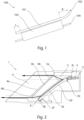
- the lighting device 100 shown according to the prior art has a light guide 101 which couples light from a light source 102 into an optical body 103 .
- the light guide 101 is longer than the optic body 103.
- a screen 104 is arranged on a left and right edge of the optic body 103.
- the light guide 101 is longer than the optic body 103 by at least sections d and c in order to achieve complete light coupling into the optic body 103 .
- the lighting device 1 comprises a light source 2 for generating and emitting light and a light guide 3 .
- the light from the light source 2 is coupled into the light guide 3 via a coupling surface of the light guide 3 .
- the light guide 3 has a deflection surface for deflecting the light coupled into the light guide 3, and a front surface opposite the deflection surface, with a region of the front surface forming a decoupling section 3a.
- the light coupled into the light guide 3 and deflected via the deflection surface is coupled out of the light guide 3 via the decoupling section 3a.
- the light is coupled out along a main emission direction.
- the light guide 3 has an end section 3b adjoining the decoupling section 3a on a side facing away from the illuminant.
- the light guide has an initial section 3c, which is arranged on a side of the light guide 3 facing the light source and in front of the decoupling section 3a in the light propagation direction.
- the front surface of the beginning portion is 3c in particular not designed as a decoupling section 3a.
- Light is preferably coupled out of the light guide exclusively via the coupling-out section 3a.
- the light guide 3 preferably has deflection prisms 3d for light guidance in the light guide 3 on a side facing away from the second optical element 5 .
- the deflection prisms 3d are arranged essentially from a prism start section 3e of the light guide 3, with the prism start section 3e being arranged after the start section 3c of the light guide 3 in the light propagation direction.
- the deflection prisms 3d are arranged in the light guide 3 up to a prism end section 3f.
- the prism end section 3f in particular directly adjoins the end section 3b of the light guide.
- the deflection prisms 3d can essentially form the deflection surface of the light guide 3 .
- the lighting device 1 also includes a first optical element 4 with a light entry surface and a light exit surface assigned to the light entry surface. Light from the light guide 3 can be coupled into the first optical element 4 via the light entry surface and can be coupled out via the light exit surface.
- the light entry surface has a first section 4a and at least one second section 4b adjoining the first section 4a. In the exemplary embodiment shown, the light entry surface has two second sections 4b, with the first section 4a being arranged between the two second sections 4b.
- the first optical element 4 is arranged relative to the light guide 3 in such a way that the light which is coupled out of the decoupling section 3a of the light guide 3 only impinges on the entire first section 4a.
- the lighting device 1 also includes a second optical element 5, which is arranged between the decoupling section 3a of the light guide 3 and the light entry surface of the first optical element 4 and is set up in such a way that light, which is decoupled from the decoupling section 3a of the light guide 3, is deflected in such a way that the light, after passing through the second optical element 5, hits the entire first section 4a and the entire second section 4b of the light entry surface of the first optical element 4.
- a light entry surface and a light exit surface of the second optical element 5 are preferably set up to fan out light beams essentially radially around the main emission direction as they pass through the second optical element 5 . Rays of light can before and after passage be oriented essentially parallel to the main emission direction by the second optical element 5 .
- the second optical element 5 On a surface 5a facing the decoupling section 3a of the light guide 3, the second optical element 5 has entry optics which are set up to direct the light, which is decoupled from the decoupling section 3a of the light guide 3, at least partially in the direction of entry into the second optical element 5 of the second section 4b of the first optical element 4 to deflect.
- the second optical element 5 has exit optics on a surface 5b facing the first optical element 4 , which are set up to deflect the light as it exits the second optical element 5 in such a way that the light strikes the second section 4b of the first optical element 4 .
- the light beams emerging from the second optical element 5 can be oriented essentially parallel to the light beams coupled out of the coupling-out section 3a of the light guide 3 .
- An envelope of the first section 4a of the light entry surface of the first optical element 4 is oriented essentially parallel to the decoupling section 3a of the light guide 3 .
- the end section 3b of the light guide is arranged on a holding element 6 .
- the holding element 6 is set up to fix the position of the light guide 3 relative to the second optical element 5 .
- the holding element 6 has a holding section in which the end section 3b of the light guide 3 is accommodated.
- the holding section is designed, for example, as a cover that encloses the end section 3b and is impermeable to light.
- the light guide 3 and the second optical element 5 are spaced apart from one another, and the first optical element 4 and the second optical element 5 are spaced apart from one another.
- the light guide is curved at least in sections, with a surface 5a of the second optical element 5 facing the light guide 3 having a curvature which is essentially the same as the curvature of the curved section of the light guide 3 .
- the first 4 and the second optical element 5 are designed as a transparent solid body.
- the lighting device 1 can be part of a motor vehicle headlight.
- the motor vehicle headlight can have at least one light module for generating a first light function and at least one lighting device 1 according to the invention for generating a second light function.
- the first light function can be a low beam or a high beam and the second light function can be a signal light or a daytime running light.
Landscapes
- Engineering & Computer Science (AREA)
- General Engineering & Computer Science (AREA)
- Physics & Mathematics (AREA)
- Microelectronics & Electronic Packaging (AREA)
- Optics & Photonics (AREA)
- Non-Portable Lighting Devices Or Systems Thereof (AREA)
Priority Applications (5)
| Application Number | Priority Date | Filing Date | Title |
|---|---|---|---|
| EP21203360.9A EP4170232A1 (fr) | 2021-10-19 | 2021-10-19 | Dispositif d'éclairage pour un véhicule automobile |
| US18/701,330 US12492791B2 (en) | 2021-10-19 | 2022-09-20 | Illumination device for a motor vehicle |
| PCT/EP2022/076003 WO2023066580A1 (fr) | 2021-10-19 | 2022-09-20 | Dispositif d'éclairage pour un véhicule automobile |
| CN202280069952.1A CN118140091A (zh) | 2021-10-19 | 2022-09-20 | 用于机动车的照射设备 |
| EP22777243.1A EP4419835B1 (fr) | 2021-10-19 | 2022-09-20 | Dispositif d'éclairage pour un véhicule automobile |
Applications Claiming Priority (1)
| Application Number | Priority Date | Filing Date | Title |
|---|---|---|---|
| EP21203360.9A EP4170232A1 (fr) | 2021-10-19 | 2021-10-19 | Dispositif d'éclairage pour un véhicule automobile |
Publications (1)
| Publication Number | Publication Date |
|---|---|
| EP4170232A1 true EP4170232A1 (fr) | 2023-04-26 |
Family
ID=78528624
Family Applications (2)
| Application Number | Title | Priority Date | Filing Date |
|---|---|---|---|
| EP21203360.9A Withdrawn EP4170232A1 (fr) | 2021-10-19 | 2021-10-19 | Dispositif d'éclairage pour un véhicule automobile |
| EP22777243.1A Active EP4419835B1 (fr) | 2021-10-19 | 2022-09-20 | Dispositif d'éclairage pour un véhicule automobile |
Family Applications After (1)
| Application Number | Title | Priority Date | Filing Date |
|---|---|---|---|
| EP22777243.1A Active EP4419835B1 (fr) | 2021-10-19 | 2022-09-20 | Dispositif d'éclairage pour un véhicule automobile |
Country Status (4)
| Country | Link |
|---|---|
| US (1) | US12492791B2 (fr) |
| EP (2) | EP4170232A1 (fr) |
| CN (1) | CN118140091A (fr) |
| WO (1) | WO2023066580A1 (fr) |
Citations (9)
| Publication number | Priority date | Publication date | Assignee | Title |
|---|---|---|---|---|
| JP2012230862A (ja) * | 2011-04-27 | 2012-11-22 | Koito Mfg Co Ltd | 車両用灯具 |
| EP2587120A1 (fr) * | 2011-10-27 | 2013-05-01 | odelo GmbH | Conduit de lumière et véhicule automobile muni d'un tel conduit de lumière |
| US20160252228A1 (en) * | 2015-02-26 | 2016-09-01 | Valeo Iluminacion | Motor vehicle light device |
| DE102015204747A1 (de) * | 2015-03-17 | 2016-09-22 | Volkswagen Aktiengesellschaft | Beleuchtungseinrichtung für ein Kraftfahrzeug |
| WO2016154647A1 (fr) * | 2015-04-02 | 2016-10-06 | Zkw Group Gmbh | Dispositif d'éclairage |
| CN208504255U (zh) * | 2018-05-31 | 2019-02-15 | 大茂伟瑞柯车灯有限公司 | 新型汽车灯 |
| US20190271447A1 (en) * | 2018-03-05 | 2019-09-05 | Hyundai Motor Company | Light guide for vehicle |
| US20190285791A1 (en) * | 2018-03-15 | 2019-09-19 | Varroc Lighting Systems, s.r.o. | Light-Guiding System, especially for the Lighting of Land Transport Means |
| CN209977826U (zh) * | 2019-07-25 | 2020-01-21 | 华域视觉科技(上海)有限公司 | 一种实现车灯均匀发光的光学系统 |
Family Cites Families (3)
| Publication number | Priority date | Publication date | Assignee | Title |
|---|---|---|---|---|
| DE102014116517B4 (de) * | 2014-11-12 | 2022-04-28 | Dr. Ing. H.C. F. Porsche Aktiengesellschaft | Beleuchtungseinrichtung |
| CN207262329U (zh) * | 2017-04-27 | 2018-04-20 | 法雷奥照明湖北技术中心有限公司 | 光束调整装置与车灯组件 |
| US12311833B1 (en) * | 2024-04-30 | 2025-05-27 | Ford Global Technologies, Llc | Vehicle marker lighting device having a light pipe |
-
2021
- 2021-10-19 EP EP21203360.9A patent/EP4170232A1/fr not_active Withdrawn
-
2022
- 2022-09-20 US US18/701,330 patent/US12492791B2/en active Active
- 2022-09-20 CN CN202280069952.1A patent/CN118140091A/zh active Pending
- 2022-09-20 EP EP22777243.1A patent/EP4419835B1/fr active Active
- 2022-09-20 WO PCT/EP2022/076003 patent/WO2023066580A1/fr not_active Ceased
Patent Citations (9)
| Publication number | Priority date | Publication date | Assignee | Title |
|---|---|---|---|---|
| JP2012230862A (ja) * | 2011-04-27 | 2012-11-22 | Koito Mfg Co Ltd | 車両用灯具 |
| EP2587120A1 (fr) * | 2011-10-27 | 2013-05-01 | odelo GmbH | Conduit de lumière et véhicule automobile muni d'un tel conduit de lumière |
| US20160252228A1 (en) * | 2015-02-26 | 2016-09-01 | Valeo Iluminacion | Motor vehicle light device |
| DE102015204747A1 (de) * | 2015-03-17 | 2016-09-22 | Volkswagen Aktiengesellschaft | Beleuchtungseinrichtung für ein Kraftfahrzeug |
| WO2016154647A1 (fr) * | 2015-04-02 | 2016-10-06 | Zkw Group Gmbh | Dispositif d'éclairage |
| US20190271447A1 (en) * | 2018-03-05 | 2019-09-05 | Hyundai Motor Company | Light guide for vehicle |
| US20190285791A1 (en) * | 2018-03-15 | 2019-09-19 | Varroc Lighting Systems, s.r.o. | Light-Guiding System, especially for the Lighting of Land Transport Means |
| CN208504255U (zh) * | 2018-05-31 | 2019-02-15 | 大茂伟瑞柯车灯有限公司 | 新型汽车灯 |
| CN209977826U (zh) * | 2019-07-25 | 2020-01-21 | 华域视觉科技(上海)有限公司 | 一种实现车灯均匀发光的光学系统 |
Also Published As
| Publication number | Publication date |
|---|---|
| US12492791B2 (en) | 2025-12-09 |
| EP4419835B1 (fr) | 2026-02-25 |
| EP4419835A1 (fr) | 2024-08-28 |
| WO2023066580A1 (fr) | 2023-04-27 |
| US20240344679A1 (en) | 2024-10-17 |
| CN118140091A (zh) | 2024-06-04 |
Similar Documents
| Publication | Publication Date | Title |
|---|---|---|
| DE102013100557B4 (de) | Beleuchtungsvorrichtung für Fahrzeuge | |
| EP2317212B1 (fr) | Dispositif d'éclairage pour un véhicule automobile | |
| DE10065020B4 (de) | Fahrzeugscheinwerfer | |
| EP4146983B1 (fr) | Dispositif d'éclairage pour un véhicule automobile | |
| DE10022420A1 (de) | Beleuchtungseinrichtung, insbesondere Leuchte, für Kraftfahrzeuge | |
| EP3112215A1 (fr) | Systeme de guides de lumiere destine a produire au moins une fonction d'eclairage et/ou une fonction de signalisation d'un phare de vehicule automobile | |
| DE102013200441B3 (de) | Kraftfahrzeugbeleuchtungseinrichtung mit einem grabenartige Vertiefungen aufweisenden Lichtleiter | |
| WO2014180813A1 (fr) | Dispositif d'éclairage pour véhicules | |
| DE102006008191B4 (de) | Leuchteneinheit für Fahrzeuge | |
| EP3899358A1 (fr) | Dispositif d'éclairage pour un phare de véhicule automobile ainsi que phare de véhicule automobile | |
| DE102017119500A1 (de) | Beleuchtungseinrichtung | |
| EP3531012A1 (fr) | Dispositif d'éclairage pour véhicules automobiles pourvu de guide de lumière allongé | |
| DE102006037797B4 (de) | Kraftfahrzeugleuchte | |
| DE10022779A1 (de) | Stabförmiger Lichtleiter | |
| EP1898147B1 (fr) | Dispositif d'éclairage pour véhicule | |
| EP1146281B1 (fr) | Lampe de signalisation avec au moins une source lumineuse et un guide de lumière | |
| EP3158260A1 (fr) | Dispositif d'éclairage de véhicule automobile | |
| DE202021106229U1 (de) | Signalleuchtvorrichtung oder Beleuchtungsvorrichtung für einen Kraftfahrzeugscheinwerfer | |
| EP4419835B1 (fr) | Dispositif d'éclairage pour un véhicule automobile | |
| DE102017119475A1 (de) | Lichtleiter | |
| DE102005059958A1 (de) | Beleuchtungseinrichtung | |
| DE102017106441A1 (de) | Kraftfahrzeugleuchte mit einem flächigen Lichtleiter | |
| EP1832902A1 (fr) | Dispositif de lampe plate | |
| DE102019211799B4 (de) | Vorrichtung zum Erzeugen einer Lichtverteilung für ein Fahrzeug | |
| DE102018123333A1 (de) | Lichtmodul für ein Kraftfahrzeug |
Legal Events
| Date | Code | Title | Description |
|---|---|---|---|
| PUAI | Public reference made under article 153(3) epc to a published international application that has entered the european phase |
Free format text: ORIGINAL CODE: 0009012 |
|
| STAA | Information on the status of an ep patent application or granted ep patent |
Free format text: STATUS: THE APPLICATION HAS BEEN PUBLISHED |
|
| AK | Designated contracting states |
Kind code of ref document: A1 Designated state(s): AL AT BE BG CH CY CZ DE DK EE ES FI FR GB GR HR HU IE IS IT LI LT LU LV MC MK MT NL NO PL PT RO RS SE SI SK SM TR |
|
| STAA | Information on the status of an ep patent application or granted ep patent |
Free format text: STATUS: THE APPLICATION IS DEEMED TO BE WITHDRAWN |
|
| 18D | Application deemed to be withdrawn |
Effective date: 20231027 |