EP4170295A1 - Appareil électrochimique pour surveiller le débit - Google Patents
Appareil électrochimique pour surveiller le débit Download PDFInfo
- Publication number
- EP4170295A1 EP4170295A1 EP21837077.3A EP21837077A EP4170295A1 EP 4170295 A1 EP4170295 A1 EP 4170295A1 EP 21837077 A EP21837077 A EP 21837077A EP 4170295 A1 EP4170295 A1 EP 4170295A1
- Authority
- EP
- European Patent Office
- Prior art keywords
- electrode
- flow rate
- fluid
- space
- membrane
- Prior art date
- Legal status (The legal status is an assumption and is not a legal conclusion. Google has not performed a legal analysis and makes no representation as to the accuracy of the status listed.)
- Pending
Links
Images



Classifications
-
- G—PHYSICS
- G01—MEASURING; TESTING
- G01F—MEASURING VOLUME, VOLUME FLOW, MASS FLOW OR LIQUID LEVEL; METERING BY VOLUME
- G01F1/00—Measuring the volume flow or mass flow of fluid or fluent solid material wherein the fluid passes through a meter in a continuous flow
- G01F1/56—Measuring the volume flow or mass flow of fluid or fluent solid material wherein the fluid passes through a meter in a continuous flow by using electric or magnetic effects
- G01F1/64—Measuring the volume flow or mass flow of fluid or fluent solid material wherein the fluid passes through a meter in a continuous flow by using electric or magnetic effects by measuring electrical currents passing through the fluid flow; measuring electrical potential generated by the fluid flow, e.g. by electrochemical, contact or friction effects
-
- A—HUMAN NECESSITIES
- A61—MEDICAL OR VETERINARY SCIENCE; HYGIENE
- A61M—DEVICES FOR INTRODUCING MEDIA INTO, OR ONTO, THE BODY; DEVICES FOR TRANSDUCING BODY MEDIA OR FOR TAKING MEDIA FROM THE BODY; DEVICES FOR PRODUCING OR ENDING SLEEP OR STUPOR
- A61M5/00—Devices for bringing media into the body in a subcutaneous, intra-vascular or intramuscular way; Accessories therefor, e.g. filling or cleaning devices, arm-rests
- A61M5/14—Infusion devices, e.g. infusing by gravity; Blood infusion; Accessories therefor
- A61M5/168—Means for controlling media flow to the body or for metering media to the body, e.g. drip meters, counters ; Monitoring media flow to the body
- A61M5/16804—Flow controllers
-
- G—PHYSICS
- G01—MEASURING; TESTING
- G01F—MEASURING VOLUME, VOLUME FLOW, MASS FLOW OR LIQUID LEVEL; METERING BY VOLUME
- G01F1/00—Measuring the volume flow or mass flow of fluid or fluent solid material wherein the fluid passes through a meter in a continuous flow
- G01F1/56—Measuring the volume flow or mass flow of fluid or fluent solid material wherein the fluid passes through a meter in a continuous flow by using electric or magnetic effects
-
- G—PHYSICS
- G01—MEASURING; TESTING
- G01F—MEASURING VOLUME, VOLUME FLOW, MASS FLOW OR LIQUID LEVEL; METERING BY VOLUME
- G01F1/00—Measuring the volume flow or mass flow of fluid or fluent solid material wherein the fluid passes through a meter in a continuous flow
- G01F1/704—Measuring the volume flow or mass flow of fluid or fluent solid material wherein the fluid passes through a meter in a continuous flow using marked regions or existing inhomogeneities within the fluid stream, e.g. statistically occurring variations in a fluid parameter
- G01F1/7046—Measuring the volume flow or mass flow of fluid or fluent solid material wherein the fluid passes through a meter in a continuous flow using marked regions or existing inhomogeneities within the fluid stream, e.g. statistically occurring variations in a fluid parameter using electrical loaded particles as tracer, e.g. ions or electrons
-
- A—HUMAN NECESSITIES
- A61—MEDICAL OR VETERINARY SCIENCE; HYGIENE
- A61M—DEVICES FOR INTRODUCING MEDIA INTO, OR ONTO, THE BODY; DEVICES FOR TRANSDUCING BODY MEDIA OR FOR TAKING MEDIA FROM THE BODY; DEVICES FOR PRODUCING OR ENDING SLEEP OR STUPOR
- A61M2205/00—General characteristics of the apparatus
- A61M2205/02—General characteristics of the apparatus characterised by a particular materials
- A61M2205/0272—Electro-active or magneto-active materials
-
- A—HUMAN NECESSITIES
- A61—MEDICAL OR VETERINARY SCIENCE; HYGIENE
- A61M—DEVICES FOR INTRODUCING MEDIA INTO, OR ONTO, THE BODY; DEVICES FOR TRANSDUCING BODY MEDIA OR FOR TAKING MEDIA FROM THE BODY; DEVICES FOR PRODUCING OR ENDING SLEEP OR STUPOR
- A61M2205/00—General characteristics of the apparatus
- A61M2205/33—Controlling, regulating or measuring
- A61M2205/3317—Electromagnetic, inductive or dielectric measuring means
-
- A—HUMAN NECESSITIES
- A61—MEDICAL OR VETERINARY SCIENCE; HYGIENE
- A61M—DEVICES FOR INTRODUCING MEDIA INTO, OR ONTO, THE BODY; DEVICES FOR TRANSDUCING BODY MEDIA OR FOR TAKING MEDIA FROM THE BODY; DEVICES FOR PRODUCING OR ENDING SLEEP OR STUPOR
- A61M2205/00—General characteristics of the apparatus
- A61M2205/33—Controlling, regulating or measuring
- A61M2205/3331—Pressure; Flow
- A61M2205/3334—Measuring or controlling the flow rate
-
- A—HUMAN NECESSITIES
- A61—MEDICAL OR VETERINARY SCIENCE; HYGIENE
- A61M—DEVICES FOR INTRODUCING MEDIA INTO, OR ONTO, THE BODY; DEVICES FOR TRANSDUCING BODY MEDIA OR FOR TAKING MEDIA FROM THE BODY; DEVICES FOR PRODUCING OR ENDING SLEEP OR STUPOR
- A61M5/00—Devices for bringing media into the body in a subcutaneous, intra-vascular or intramuscular way; Accessories therefor, e.g. filling or cleaning devices, arm-rests
- A61M5/14—Infusion devices, e.g. infusing by gravity; Blood infusion; Accessories therefor
- A61M5/168—Means for controlling media flow to the body or for metering media to the body, e.g. drip meters, counters ; Monitoring media flow to the body
- A61M5/16886—Means for controlling media flow to the body or for metering media to the body, e.g. drip meters, counters ; Monitoring media flow to the body for measuring fluid flow rate, i.e. flowmeters
Definitions
- the present invention relates to an electrochemical apparatus for monitoring flow rate.
- a drug injection pump has to be precisely controlled and injected to be effective in treatment and to minimize side effects caused by misinjection (overinjection or underinjection).
- the drug injection pump used in hospitals and the like includes a volumetric pump, a syringe pump, and an implantable pump.
- flow rate monitoring is not accurately measured and controlled. This is because there is no technology for precisely measuring a flow rate of microliters or nanoliters that may be used individually.
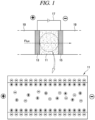
- FIG. 1 is a diagram illustrating an electrode used in the conventional electroosmotic pump.
- the electroosmotic pump uses movement of a fluid due to an electroosmotic phenomenon occurring when a voltage is applied by using electrodes at both ends of a porous member (porous membrane).
- Silica, glass, and so on are generally used as a material for the porous membrane, and when the material is immersed in an aqueous solution, a surface thereof is negatively charged. In this state, when a voltage is applied thereto, a fluid moves from a positive (+) electrode to a negative (-) electrode (see upper figure of FIG. 1 ).
- the porous membrane has many passages through which a number of fluids may pass.
- a surface of the fluid passage (which becomes a surface of a porous membrane material) has a negative charge (bound anion), and thereby, positive ions (mobile cations) with positive (+) charges that may move in a contacting fluid move to balance the charges.
- positive ions (mobile cations) move along the surface from the positive (+) electrode to the negative (-) electrode. Accordingly, a phenomenon occurs in which the entire fluid connected by a hydrogen bond network flows in a sliding manner, which is called an electroosmosis phenomenon, and a pump using this principle is the electroosmotic pump.
- an electrode used in an electroosmotic pump is coated with a platinum mesh that is a porous electrode, porous carbon paper or carbon cloth, or a variety of electrode materials to be coated on a porous structure so as to facilitate fluid movement.
- a voltage is applied to the electrode with a porous film formed of silica or so on interposed therebetween, the fluid moves accordingly.
- a flow rate of the electroosmotic pump may be adjusted by a magnitude of a voltage, time during which the voltage is applied, and so on. Therefore, in order to improve the injection accuracy of the electroosmotic pump, a precise flow rate monitoring device capable of providing feedback on the flow rate is required.
- ACS Sensors 2019 a flow rate measurement device that uses an electrochemical polarization phenomenon has been reported (ACS Sensors 2019).
- the device uses a method in which, instead of directly measuring a current, a separate electrode pair that causes the concentration polarization is provided, and impedance is measured with another electrode pair in a passage through which a fluid passes. Since the electrode directly touches the fluid to be measured, there is a risk of contamination when the fluid is a drug.
- An embodiment of the present invention provides an electrochemical apparatus for monitoring flow rate that precisely monitors a flow rate of microliters or nanoliters to prevent risks and side effects caused by overinjection and underinjection of a drug without contamination of the drug and injects a solution with a certain ion concentration.
- an electrochemical apparatus for monitoring flow rate includes a membrane having a space that is formed in a middle portion of the membrane and has a preset volume to contain an ionic fluid, a first electrode and a second electrode provided on both sides of the membrane, and a control unit configured to apply a voltage to the first electrode and the second electrode to change a state of the space to a concentration polarization state, wherein the membrane includes a fluid flow passage through which a fluid flows into and out of the space, and the control unit calculates a flow rate based on an ionic current generated by the fluid injected through the fluid flow passage in the concentration polarization state.
- the fluid may have a low ion concentration of 0.1 mM to 10 mM.
- the space of the membrane may have a volume of 2 ⁇ L to 4 ⁇ L.
- a distance between the first electrode and the second electrode may be 50um to 1 mm.
- the electrochemical apparatus for monitoring flow rate may further include connection portions formed in a protruding shape on one side of the first electrode and one side of the second electrode and electrically connected to the control unit.
- the electrochemical apparatus for monitoring flow rate may further include a pumping unit connected to the fluid flow passage and configured to inject a fluid having a preset flow rate into the space.
- the control unit may include a power supply unit configured to supply a preset voltage to the first electrode and the second electrode, and a measurement unit configured to measure an ionic current generated by ions of the fluid injected into the space which move to both ends of the first electrode and the second electrode.
- concentration polarization and a current or electric charges proportional to a flow rate may be measured by a pair of electrodes. Therefore, the present invention is not only structurally different from the conventional art including a separate electrode pair causing concentration polarization, but also provides a much simpler form.
- the flow rate measurement according to the present invention may be applied to all solutions having a certain ion concentration and is very useful for application to electroosmotic pumps that utilize solutions with a low ion concentration of about 0.1 to 10 mM.
- the flow rate monitoring device when the flow rate monitoring device according to the present invention is connected to the existing electroosmotic pump through feedback of a flow rate, the flow rate may be controlled much more accurately.
- the flow rate monitoring device may be used for various other quantitative injections in addition to drugs and may solve a bottle-neck problem that currently appears in the development field of flow rate sensors.
- the present invention includes a technology that increases injection accuracy of a micro-precision pump such as a drug pump by precisely monitoring a flow rate of microliters or nanoliters, and an electrochemical principle is applied to the technology.
- ionicity (ion concentration) of a solution may be applied to determine a flow rate of a constant solution.
- an ionic liquid a fluid, a solution
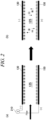
- concentration polarization of ions is induced by applying a voltage between two electrodes
- the ions contained in the liquid move to both ends of the electrodes, and thereby, a current (ionic current) is measured.
- the measured current or charges may be used as a quantitative index associated with the flow rate.
- FIG. 2 illustrates principle of measuring an ionic current according to injection of an ionic solution after polarization, according to an embodiment of the present invention.
- FIG. 3 illustrates a fluid flow passage coupled to an electrode for a flow rate sensor and a pumping configuration according to an embodiment of the present invention.
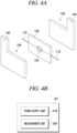
- FIG. 4A is a view schematically illustrating a membrane arranged between electrodes for a flow rate sensor, according to an embodiment of the present invention.
- FIG. 4B is a block diagram illustrating a configuration of a control unit according to an embodiment of the present invention.
- an electrochemical apparatus for monitoring flow rate includes a pumping unit 10, a fluid flow passage 110, a membrane 120 having a space 125, a first electrode 130, a connection portion 140, a second electrode 150, and a control unit 20 including a power supply unit 210 and a measurement unit 220.
- the flow rate monitoring device includes the membrane 120 having the space 125 which is formed in the middle thereof and has a preset volume to contain an ionic fluid, the first electrode 130 and the second electrode 150 provided on both sides of the membrane 120, and the control unit 20 that changes a space into a concentration polarization state by applying a voltage to the first electrode 130 and the second electrode 150.
- the membrane 120 includes the fluid flow passage 110 through which a fluid flows into and out of the space.
- the control unit 20 calculates a flow rate of a fluid injected through the fluid flow passage 110 in the concentration polarization state, based on an ionic current value generated by the fluid.
- the fluid may be a solution with a low ion concentration of 0.1 mM to 10 mM but is not limited thereto.
- the solution with a low ion concentration of about 0.1 mM to 10 mM is generally used for an electroosmotic pump, and electroosmosis is more advantageous when the solution has a lower ion concentration.
- FIG. 4A is a perspective view schematically illustrating an arrangement relationship between the first electrode 130, the membrane 120, and the second electrode 150 illustrated in FIG. 3 .
- the first electrode 130 and the second electrode 150 may be arranged on both sides of the membrane 120.
- first electrode 130 and the second electrode 150 may respectively include the connection portions 140 each protruding from one side.
- connection portions 140 may be electrically connected to the control unit 20.
- the membrane 120 may have a preset volume and may include the space 125 in which an ionic fluid is introduced through the fluid flow passage 110 to be and contained therein.
- the membrane 120 may be formed of a non-porous thin film. Accordingly, a fluid may be injected into the space 125 through the fluid flow passage 110, and the injected fluid may be contained in the space 125.
- the space 125 of the membrane 120 may be formed to have a volume of 2 ⁇ L to 4 ⁇ L and serves to contain a fluid.
- the space 125 has a circle shape to have a diameter of 2 mm, a thickness of 1 mm, and a volume of about 3 ⁇ L.
- a shape of the passage is not limited to a circle shape, and may be formed to have various volumes depending on flow rates.
- first electrode 130 and the second electrode 150 are coupled to both sides of the membrane 120 illustrated in FIG. 4A , and the pumping unit 10 illustrated in FIG. 3 may be connected to the fluid flow passage 110.
- the pumping unit 10 may be connected to the fluid flow passage 110 to inject a fluid at a preset flow rate into the space 125.
- the pumping unit 10 may be connected to the conventional electroosmotic pump to control a flow rate but is not limited thereto.
- a combined electrode for a flow rate sensor may include the first electrode 130 and the second electrode 150 facing each other and having the space 125 formed therebetween to penetrate the middle of the membrane 120.
- a distance between the first electrode 130 and the second electrode 150 may be 50um to 1 mm.
- the power supply unit 210 may apply a voltage that does not cause electrolysis to both ends of the first electrode 130 and the second electrode 150 such that the space 125 of the membrane 120 between the first electrode 130 and the second electrode 150 changes to a concentration polarization state.
- the power supply unit 210 may apply a voltage of 1.0 V.
- control unit 20 may measure a current or the amount of electric charges generated inside the space 125 and calculate a minute volume of a fluid based on the measured value.
- the control unit 20 may include the power supply unit 210 that supplies a preset voltage to the first electrode 130 and the second electrode 150, and the measurement unit 220 that measures an ionic current generated when ions of the fluid injected into the space 125 move to both ends of the first electrode 130 and the second electrode 150.
- the connection portions 140 protruding from the first electrode 130 and the second electrode 150 illustrated in FIG. 4A may be connected to the control unit 20.
- the electrochemical apparatus for monitoring flow rate includes the space 125 formed to have a certain volume in the middle of a double-sided tape 150 (membrane) between the first and second electrodes 130 and 150, and the fluid flow passage 110 through which the solution may come in and out the space 125.
- the electrochemical apparatus for monitoring flow rate includes connection portions 140 provided at both ends of the electrodes 130 and 150 to measure a current when a voltage is applied from the outside.
- the circle space 125 which is a passage that contains a fluid and serves as a flow rate sensor, has a diameter of 2 mm, a thickness of 1 mm, and a volume of about 3 ⁇ L.
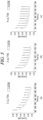
- FIG. 5 illustrates graphs of changes in current characteristics according to injection of an ionic solution between electrodes polarized at intervals of 1 mm, according to an embodiment of the present invention.
- a voltage of 1.0 V is applied to the first and second electrodes 130 and 150 to change an internal state of the space 125 to a concentration polarization state.
- solutions Li2SO4 of 0.5 mM were injected respectively by 2 ⁇ L, 3 ⁇ L, and 4 ⁇ L for 10 seconds by using the pumping unit 10 (a syringe pump), and current characteristics were observed.
- the pumping unit 10 a syringe pump
- FIG. 5(a) to FIG. 5(c) when a fluid (solution) of 2 ⁇ L, a fluid (solution) of 3 ⁇ L, and a fluid (solution) of 4 ⁇ L are sequentially injected, the current characteristics show that the current is reduced with time.
- FIG. 6A is a graph of linearity of a flow rate and a current, according to an embodiment of the present invention.
- a peak current may be associated with a flow rate.
- the solution is 4 ⁇ L, it is estimated that the current is slightly reduced because a volume of the solution is slightly greater than a volume of the space 125.
- FIG. 6B is a graph of stability of a current according to a flow rate, according to an embodiment of the present invention.
- FIG. 7 is a graph illustrating a change in current characteristics according to injection of an ionic solution between electrodes polarized at intervals of 50um, according to an embodiment of the present invention.
- a flow rate sensor of an example 3 has a structure similar to the flow rate sensor of example 2, and a current was measure by using the flow rate sensor in which the distance between the electrodes 130 and 150 is 50um that is reduced by 1/20 and areas of the electrodes are increased by 18 times to 3 mm x 19 mm.
- an internal volume of the space 125 was 3 ⁇ L which is similar to the volume in Example 2.
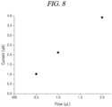
- FIG. 8 is a graph illustrating a current change according to a flow rate according to an embodiment of the present invention.
Landscapes
- Health & Medical Sciences (AREA)
- Fluid Mechanics (AREA)
- Physics & Mathematics (AREA)
- General Physics & Mathematics (AREA)
- Biomedical Technology (AREA)
- Heart & Thoracic Surgery (AREA)
- Chemical Kinetics & Catalysis (AREA)
- Vascular Medicine (AREA)
- Engineering & Computer Science (AREA)
- Anesthesiology (AREA)
- Chemical & Material Sciences (AREA)
- Electrochemistry (AREA)
- Hematology (AREA)
- Life Sciences & Earth Sciences (AREA)
- Animal Behavior & Ethology (AREA)
- General Health & Medical Sciences (AREA)
- Public Health (AREA)
- Veterinary Medicine (AREA)
- Infusion, Injection, And Reservoir Apparatuses (AREA)
- Measuring Volume Flow (AREA)
Applications Claiming Priority (3)
| Application Number | Priority Date | Filing Date | Title |
|---|---|---|---|
| KR20200085710 | 2020-07-10 | ||
| KR1020210089241A KR102734938B1 (ko) | 2020-07-10 | 2021-07-07 | 전기화학적 유량모니터링 장치 |
| PCT/KR2021/008690 WO2022010276A1 (fr) | 2020-07-10 | 2021-07-08 | Appareil électrochimique pour surveiller le débit |
Publications (2)
| Publication Number | Publication Date |
|---|---|
| EP4170295A1 true EP4170295A1 (fr) | 2023-04-26 |
| EP4170295A4 EP4170295A4 (fr) | 2024-06-26 |
Family
ID=79553446
Family Applications (1)
| Application Number | Title | Priority Date | Filing Date |
|---|---|---|---|
| EP21837077.3A Pending EP4170295A4 (fr) | 2020-07-10 | 2021-07-08 | Appareil électrochimique pour surveiller le débit |
Country Status (4)
| Country | Link |
|---|---|
| US (1) | US12474189B2 (fr) |
| EP (1) | EP4170295A4 (fr) |
| JP (1) | JP7577266B2 (fr) |
| WO (1) | WO2022010276A1 (fr) |
Families Citing this family (1)
| Publication number | Priority date | Publication date | Assignee | Title |
|---|---|---|---|---|
| EP4720610A2 (fr) * | 2023-05-26 | 2026-04-08 | Carnegie Mellon University | Systèmes et procédés de détection d'écoulement de fluide |
Family Cites Families (13)
| Publication number | Priority date | Publication date | Assignee | Title |
|---|---|---|---|---|
| EP0077413A1 (fr) * | 1981-10-20 | 1983-04-27 | Memorial Hospital for Cancer and Allied Diseases | Procédé et appareil pour mesurer électriquement des débits d'un fluide |
| AU614987B2 (en) * | 1985-05-20 | 1991-09-19 | Nabil I. Rizk | Implantable electrophoretic pump for ionic drugs and associated methods |
| US4953407A (en) * | 1988-08-08 | 1990-09-04 | General Motors Corporation | Ion-drag flowmeter |
| JPH10274661A (ja) * | 1997-03-31 | 1998-10-13 | Sumitomo Metal Mining Co Ltd | 電解液の流速測定装置および方法 |
| KR100292799B1 (ko) * | 1998-11-20 | 2002-02-28 | 정선종 | 멤브레인구조의마이크로유량/유속센서,및그를이용한유량/유속측정방법 |
| JP2003042827A (ja) * | 2001-07-26 | 2003-02-13 | Sefa Technology Kk | 容器内試料の分量測定方法およびその装置 |
| JP4613099B2 (ja) * | 2005-06-03 | 2011-01-12 | シャープ株式会社 | 電気化学検出装置 |
| US8133373B2 (en) * | 2008-08-15 | 2012-03-13 | Dionex Corporation | Electrochemically driven pump |
| JP5331782B2 (ja) * | 2010-12-07 | 2013-10-30 | 株式会社日立ハイテクノロジーズ | 電極,電気化学セルおよび分析装置並びにそれらの製造方法 |
| JP2012122883A (ja) * | 2010-12-09 | 2012-06-28 | Kyoto Institute Of Technology | イオン性物質の絶対定量装置およびイオン性物質の絶対定量方法 |
| KR101484540B1 (ko) * | 2013-12-19 | 2015-01-20 | 한국과학기술원 | 유량 센서 |
| DE102015001406B3 (de) * | 2015-02-04 | 2016-07-14 | Fresenius Medical Care Deutschland Gmbh | Kassettenmodul für einen Differenzflussmesser und Differenzflussmesser |
| IL239691A0 (en) * | 2015-06-28 | 2015-08-31 | Technion Res & Dev Foundation | Device and method for measuring flow in a channel |
-
2021
- 2021-07-08 EP EP21837077.3A patent/EP4170295A4/fr active Pending
- 2021-07-08 WO PCT/KR2021/008690 patent/WO2022010276A1/fr not_active Ceased
- 2021-07-08 JP JP2023501572A patent/JP7577266B2/ja active Active
-
2023
- 2023-01-10 US US18/095,088 patent/US12474189B2/en active Active
Also Published As
| Publication number | Publication date |
|---|---|
| US12474189B2 (en) | 2025-11-18 |
| WO2022010276A1 (fr) | 2022-01-13 |
| US20230158233A1 (en) | 2023-05-25 |
| JP2023539004A (ja) | 2023-09-13 |
| JP7577266B2 (ja) | 2024-11-05 |
| EP4170295A4 (fr) | 2024-06-26 |
Similar Documents
| Publication | Publication Date | Title |
|---|---|---|
| CA2838176C (fr) | Compensation de volume d'echantillonnage inadequat dans les dispositifs biodetecteurs | |
| CA2412204C (fr) | Determination de l'adequation du volume d'echantillon dans des dispositifs a biocapteurs | |
| US6236873B1 (en) | Electrochemical sensor | |
| US20180353748A1 (en) | Reverse iontophoresis biosensing with reduced sample volumes | |
| Aguilella et al. | Estimation of the pore size and charge density in human cadaver skin | |
| EP2856133B1 (fr) | Procédé et dispositif améliorés pour la détection de la concentration d'un médicament bio-disponible | |
| Reuss et al. | Intracellular ion activities and Cl-transport mechanisms in bullfrog corneal epithelium | |
| US12474189B2 (en) | Electrochemical apparatus for monitoring flow rate | |
| Yoshitomi et al. | How big is the electrochemical potential difference of Na+ across rat renal proximal tubular cell membranes in vivo? | |
| Jaworska et al. | Advantages of Amperometric Readout Mode of Ion‐selective Electrodes under Potentiostatic Conditions | |
| DE69828319T2 (de) | Verfahren und gerät zur messung der blut-koagulation oder lyse mit hilfe von viskositätsveränderungen | |
| Jin et al. | Measurement of chloramphenicol by capillary zone electrophoresis following end-column amperometric detection at a carbon fiber micro-disk array electrode | |
| KR102734938B1 (ko) | 전기화학적 유량모니터링 장치 | |
| Jin et al. | Determination of clozapine by capillary zone electrophoresis following end‐column amperometric detection with simplified capillary/electrode alignment | |
| CA2221307A1 (fr) | Amelioration d'un reservoir ionique par l'application d'un potentiel electrique | |
| US3657095A (en) | Electrode system for measuring ion activity having sensing and unknown solutions in direct contact | |
| EP0068025A1 (fr) | Electrode de reference | |
| EP2844990A1 (fr) | Essais par signaux pulsés d'un fluide biologique | |
| KR100700713B1 (ko) | 신규한 폴리전해질 참조전극을 포함하는 소형화된 전기화학시스템 및 이것의 박층 전기분석으로의 응용 | |
| Sheybani et al. | Design, fabrication, and characterization of an electrochemically-based dose tracking system for closed-loop drug delivery | |
| Liu et al. | Online concentration by head-column field-amplified with large-volume sample stacking using flow injection-capillary electrophoresis for the analysis of four active components in cold medicines | |
| EP4722705A1 (fr) | Dispositif de détection électrochimique à jauge et procédé correspondant pour l'évaluation d'un analyte dans un échantillon de fluide | |
| Powley et al. | Bipolar pulse conductometric monitoring of ion-selective electrodes: Part 3. Studies with the calcium and fluoride electrodes in a continuous flow system | |
| Vance et al. | Capacitively-Coupled Contactless Conductivity Detection (C4D) for In-Line Ionic Silver Monitoring | |
| Foresti et al. | Electrode charge measurements at dropping electrodes: Part II. Chronocoulometric measurement of absolute values of charge with a pressurized electrode |
Legal Events
| Date | Code | Title | Description |
|---|---|---|---|
| STAA | Information on the status of an ep patent application or granted ep patent |
Free format text: STATUS: THE INTERNATIONAL PUBLICATION HAS BEEN MADE |
|
| PUAI | Public reference made under article 153(3) epc to a published international application that has entered the european phase |
Free format text: ORIGINAL CODE: 0009012 |
|
| STAA | Information on the status of an ep patent application or granted ep patent |
Free format text: STATUS: REQUEST FOR EXAMINATION WAS MADE |
|
| 17P | Request for examination filed |
Effective date: 20230119 |
|
| AK | Designated contracting states |
Kind code of ref document: A1 Designated state(s): AL AT BE BG CH CY CZ DE DK EE ES FI FR GB GR HR HU IE IS IT LI LT LU LV MC MK MT NL NO PL PT RO RS SE SI SK SM TR |
|
| DAV | Request for validation of the european patent (deleted) | ||
| DAX | Request for extension of the european patent (deleted) | ||
| A4 | Supplementary search report drawn up and despatched |
Effective date: 20240528 |
|
| RIC1 | Information provided on ipc code assigned before grant |
Ipc: A61M 5/142 20060101ALI20240523BHEP Ipc: A61M 5/172 20060101ALI20240523BHEP Ipc: A61M 5/168 20060101ALI20240523BHEP Ipc: G01F 1/64 20060101AFI20240523BHEP |