EP4170330A1 - Dispositif d'inspection de câble et procédé d'inspection de câble - Google Patents
Dispositif d'inspection de câble et procédé d'inspection de câble Download PDFInfo
- Publication number
- EP4170330A1 EP4170330A1 EP21829123.5A EP21829123A EP4170330A1 EP 4170330 A1 EP4170330 A1 EP 4170330A1 EP 21829123 A EP21829123 A EP 21829123A EP 4170330 A1 EP4170330 A1 EP 4170330A1
- Authority
- EP
- European Patent Office
- Prior art keywords
- cable
- neutrons
- neutron
- target
- incident
- Prior art date
- Legal status (The legal status is an assumption and is not a legal conclusion. Google has not performed a legal analysis and makes no representation as to the accuracy of the status listed.)
- Pending
Links
Images



Classifications
-
- G—PHYSICS
- G01—MEASURING; TESTING
- G01N—INVESTIGATING OR ANALYSING MATERIALS BY DETERMINING THEIR CHEMICAL OR PHYSICAL PROPERTIES
- G01N23/00—Investigating or analysing materials by the use of wave or particle radiation, e.g. X-rays or neutrons, not covered by groups G01N3/00 – G01N17/00, G01N21/00 or G01N22/00
- G01N23/20—Investigating or analysing materials by the use of wave or particle radiation, e.g. X-rays or neutrons, not covered by groups G01N3/00 – G01N17/00, G01N21/00 or G01N22/00 by using diffraction of the radiation by the materials, e.g. for investigating crystal structure; by using scattering of the radiation by the materials, e.g. for investigating non-crystalline materials; by using reflection of the radiation by the materials
- G01N23/20008—Constructional details of analysers, e.g. characterised by X-ray source, detector or optical system; Accessories therefor; Preparing specimens therefor
-
- G—PHYSICS
- G01—MEASURING; TESTING
- G01N—INVESTIGATING OR ANALYSING MATERIALS BY DETERMINING THEIR CHEMICAL OR PHYSICAL PROPERTIES
- G01N23/00—Investigating or analysing materials by the use of wave or particle radiation, e.g. X-rays or neutrons, not covered by groups G01N3/00 – G01N17/00, G01N21/00 or G01N22/00
- G01N23/02—Investigating or analysing materials by the use of wave or particle radiation, e.g. X-rays or neutrons, not covered by groups G01N3/00 – G01N17/00, G01N21/00 or G01N22/00 by transmitting the radiation through the material
- G01N23/06—Investigating or analysing materials by the use of wave or particle radiation, e.g. X-rays or neutrons, not covered by groups G01N3/00 – G01N17/00, G01N21/00 or G01N22/00 by transmitting the radiation through the material and measuring the absorption
- G01N23/09—Investigating or analysing materials by the use of wave or particle radiation, e.g. X-rays or neutrons, not covered by groups G01N3/00 – G01N17/00, G01N21/00 or G01N22/00 by transmitting the radiation through the material and measuring the absorption the radiation being neutrons
-
- G—PHYSICS
- G01—MEASURING; TESTING
- G01N—INVESTIGATING OR ANALYSING MATERIALS BY DETERMINING THEIR CHEMICAL OR PHYSICAL PROPERTIES
- G01N33/00—Investigating or analysing materials by specific methods not covered by groups G01N1/00 - G01N31/00
- G01N33/20—Metals
- G01N33/204—Structure thereof, e.g. crystal structure
- G01N33/2045—Defects
-
- G—PHYSICS
- G01—MEASURING; TESTING
- G01N—INVESTIGATING OR ANALYSING MATERIALS BY DETERMINING THEIR CHEMICAL OR PHYSICAL PROPERTIES
- G01N23/00—Investigating or analysing materials by the use of wave or particle radiation, e.g. X-rays or neutrons, not covered by groups G01N3/00 – G01N17/00, G01N21/00 or G01N22/00
- G01N23/22—Investigating or analysing materials by the use of wave or particle radiation, e.g. X-rays or neutrons, not covered by groups G01N3/00 – G01N17/00, G01N21/00 or G01N22/00 by measuring secondary emission from the material
Definitions
- the present invention relates to a device and a method for inspecting a cable used for supporting a bridge such as a cable-stayed bridge, a suspension bridge, or an extradosed bridge.
- Cables are used for supporting various types of bridges.
- a cable-stayed bridge cables are stretched between a tower and a bridge girder, and the bridge girder is supported by the tower via a plurality of the cables.
- Each of cables supporting various types of bridges such as a cable-stayed bridge, a suspension bridge, and an extradosed bridge is configured so as to include a bundle of many metal wires and a cover layer (e.g., a protective tube) that covers the bundle.
- Patent Literature 1 for example, a coil and a circuit are prepared, the coil generates eddy current in a cable, and the circuit measures an impedance of the coil. Based on the measured impedance value, it is determined whether damage or fracture exists in metal wires (steel wires) inside the cable.
- Patent Literature 1 Japanese Patent Application Laidopen Publication No. 2018-119970
- Non-Patent Literature 1 URL 1 for data on the scattering cross section of neutrons to iron: https://wwwndc.jaea.go.jp/jendl/j40/J40_J.html#index2; and URL 2 for data on the scattering cross section of neutrons to iron: https://wwwndc.jaea.go.jp/j40fig/jpeg/fe056_f1.jpg
- Damage or fracture of metal wires that constitute a cable is caused by rusting of the metal wires. Accordingly, it is desirable to inspect whether water causing rusting of metal wires exists inside a cable. When water is detected as a result of the inspection on existence or nonexistence of water causing rusting of metal wires, an appropriate measure can be taken such that water does not exist inside the cable. This can reduce a possibility that the metal wires are damaged or fractured.
- an object of the present invention is to provide a cable inspection device and a cable inspection method that can non-destructively inspect whether water exists inside a cable used for supporting a bridge, from outside the cable.
- a cable inspection device is a device for non-destructively inspecting a cable used for supporting a bridge
- a cable inspection method is a method for non-destructively inspecting a cable used for supporting a bridge, the method including:
- the neutrons in the case where water exists inside the cable, when neutrons are emitted to the cable, the neutrons react with the water, and thus, reduce their own energies. For this reason, based on the number of the detected target neutrons corresponding to the neutrons having the reduced energies, it can be determined whether water exists inside the cable.
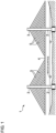
- FIG. 1 illustrates one example of a cable-stayed bridge 1 as an inspection target of a cable inspection device 10 according to the present invention.
- the cable-stayed bridge 1 includes a pier 2 and a bridge girder 4 supported by the pier 2.
- the cable-stayed bridge 1 is supported by a plurality of cables 5.
- each cable 5 is stretched between a tower 3 provided on the pier 2 and the bridge girder 4, and supports the bridge girder 4.
- the bridge girder 4 is supported by the tower 3 via the cables 5.
- respective both end portions of each cable 5 are coupled to the tower 3 and the bridge girder 4.
- the one end portion of each cable 5 may be coupled to the bridge girder 4 via a reinforcement member (e.g., a truss) of the bridge girder 4.
- a reinforcement member e.g., a truss
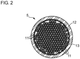
- FIG. 2 is a cross-sectional view of one cable 5.
- the cable 5 is configured so as to include a plurality (e.g., a large number) of metal wires 11 and a cover layer 12.
- Each of the metal wires 11 is, for example, a steel wire formed of steel whose main component is iron.
- the cover layer 12 covers an entire outer periphery of a bundle of a plurality of the metal wires 11.
- the cover layer 12 extends in a longitudinal direction of the cable 5.
- the cover layer 12 is formed of a highly weather-resistant material (e.g., synthetic resin such as polyethylene or fluororesin).
- the cover layer 12 may be a protective tube that accommodates the bundle of the metal wires 11 inside.
- the cable 5 may include a restriction portion 13 that bundles the metal wires 11 inside the cover layer 12, as illustrated in FIG. 2 .
- a diameter of the bundle of the metal wires 11 may be equal to or larger than 100 mm, for example, but is not limited to this.
- Each of cables that support other bridges such as a suspension bridge and an extradosed bridge also has the same configuration as that of the above-described cable 5. Accordingly, the cable 5 described below has the above-described configuration, and may be a cable that supports the cable-stayed bridge 1, or may be a cable that supports a different bridge such as a suspension bridge or an extradosed bridge.
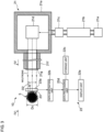
- FIG. 3 illustrates a configuration example of a cable inspection device 10 according to a first embodiment of the present invention.
- FIG. 4 is an illustration viewed in a direction of the arrows IV-IV in FIG. 3 .
- the cable inspection device 10 is a device for non-destructively inspecting the cable 5 that supports an existing bridge. More specifically, the cable inspection device 10 is used for inspecting whether water exists inside the cable 5.
- the cable inspection device 10 emits neutrons to the cable 5, and detects neutrons that are among neutrons released from the cable 5 included in the emitted neutrons and that each have energy equal to or lower than a predetermined value. The predetermined value is lower than energy of a fast neutron.
- the cable inspection device 10 includes a neutron source 21 and a neutron detection device 22.
- the neutron source 21 emits, from outside the cable 5, neutrons to the cable 5 as an inspection target.
- the neutron source 21 may be configured so as to emit a pulsed neutron beam having a minute pulse time width (e.g., approximately 0.1 millisecond), or may be configured so as to continuously emit neutrons.
- the neutron source 21 emits neutrons to the cable 5 in a direction intersecting with (e.g., perpendicular to) the longitudinal direction (hereinafter, simply referred to also as the cable longitudinal direction) of the cable 5.
- the neutron source 21 includes an ion source 21a, an acceleration device 21b, a beam adjuster 21c, a target 21d, a container 21e, and a tubular shielding member 21f.
- the ion source 21a generates hydrogen ions (protons), for example.
- the acceleration device 21b accelerates the protons generated by the ion source 21a.
- the beam adjuster 21c includes a plurality of magnetic field coils that adjust, to the target 21d, a direction and a spread of the proton beam accelerated by the acceleration device 21b. After passing the beam adjuster 21c, the proton beam is incident on the target 21d.
- neutrons are generated by reaction between the protons and the target 21d (e.g., beryllium).
- the target 21d is arranged in the container 21e formed of a material difficult for neutrons and gamma rays to pass through.
- a hole is formed so as to penetrate from an outer surface of the container 21e to its inside.
- the tubular shielding member 21f for neutron emission is attached to this hole.
- the tubular shielding member 21f is formed of a material difficult for neutrons to pass through.
- the neutrons generated from the target 21d pass through an inside of the tubular shielding member 21f, and are thus released as a neutron beam so as to be emitted to the cable 5.
- Such the neutron source 21 can be configured small in size to such an extent that the neutron source 21 can be transported.
- the neutron source 21 can be transported to a bridge as an inspection target, and can be arranged at a position for emitting neutrons to the cable 5.
- the neutron detection device 22 includes a detection surface 23 arranged outside the cable 5.
- the neutron detection device 22 detects neutrons (hereinafter, simply referred to also as target neutrons) that are among neutrons released from the cable 5 and then incident on the detection surface 23 and that each have energy equal to or lower than the predetermined value.
- This predetermined value is lower than energy (10 5 eV) of a fast neutron.
- the neutron detection device 22 measures the number of the detected target neutrons.
- the neutron detection device 22 includes a neutron detector 22a, a data generation unit 22b, a storage unit 22c, and a data processing unit 22d.
- the neutron detector 22a includes the two-dimensional detection surface 23 for detecting neutrons from the cable 5.
- the neutrons are moderated by the water, and thus reduce their own energies (e.g., become thermal neutrons).
- the neutron detector 22a is configured so as to detect target neutrons that are among neutrons incident on the detection surface 23 and that each have energy equal to or lower than the predetermined value.
- this predetermined value is a value equal to or higher than 1 meV and equal to or lower than 10 eV (e.g., this predetermined value is a value within a range from several milli-electron-volts to several electron-volts eV).
- the predetermined value may be a value equal to or higher than 1 eV and equal to or lower than 1 ⁇ 10 eV, or a value equal to or higher than 10 eV and equal to or lower than 1 ⁇ 10 2 eV, or a value equal to or higher than 1 ⁇ 10 2 eV and equal to or lower than 1 ⁇ 10 3 eV, or a value equal to or higher than 1 ⁇ 10 3 eV and equal to or lower than 1 ⁇ 10 4 eV, or a value within another range.
- An energy range of detectable neutrons varies depending on neutron detectors. Accordingly, a detector that detects neutrons each having energy within the above-described energy range may be selected as the neutron detector 22a. Alternatively, a measurement system of the neutron detector 22a may be designed so as to detect neutrons each having energy within the above-described energy range.
- the detection surface 23 may be planar. At the time of inspection, the detection surface 23 is arranged so as to face an outer peripheral surface of the cable 5. Each time the target neutron is incident on the detection surface 23, the neutron detector 22a detects the target neutron, and outputs a detection signal indicating an incident position that is on the detection surface 23 and on which the target neutron is incident.
- the data generation unit 22b generates and outputs detection data, based on the respective detection signals output from the neutron detector 22a.
- the detection data represent, for each position on the detection surface 23, the number (hereinafter, simply referred to also as the number of incident neutrons) of the target neutrons incident on this position.
- the data generation unit 22b may generate the detection data, based on the respective detection signals generated over a measurement period from a detection start time point to a detection end time point.
- the detection start time point may be a time point when the neutron source 21 starts to emit the pulsed neutrons.
- the detection end time point may be an expected time point when the total number of the target neutrons incident on the detection surface 23 of the neutron detector 22a in a short unit time becomes sufficiently smaller than that at the peak time, and may be predetermined by estimation.
- the detection data indicate, for each position on the detection surface 23, the total number of the target neutrons incident on this position in the measurement period.
- a length of the measurement period is, for example, approximately 10 minutes, but is not limited to this.
- the storage unit 22c stores reference data that correspond to the detection data and that are acquired for a sound cable having the same structure as that of the inspection-target cable 5.
- the above-described detection data are acquired by the cable inspection device 10 for a cable that has the same structure (materials, dimensions, and the like) as that of the inspection-target cable 5 and that does not contain a defective portion such as water inside, and the thus-acquired detection data are used as the reference data.
- the reference data and the detection data detected at the time of actual inspection are preferably acquired by the same cable inspection device 10, for cables having the same structure under the same conditions
- the data processing unit 22d generates and outputs difference data (processed data) that represent, for each position on the detection surface 23, a difference between the number of incident neutrons in the reference data and the number of the incident neutrons in the detection data.
- a display unit 22e displays, on its screen, the difference data output from the data processing unit 22d.
- the display unit 22e displays, as the difference data, the two-dimensional detection surface 23 and an indication (e.g., a color, shade, or a numerical value) that represents, at each position on the detection surface 23, the above-described difference of this position.
- the difference data are output to the display unit 22e in this example, but may be output to another part (e.g., an appropriate storage device).
- the energy of the neutron that is resonantly scattered due to the metal wire 11 when the neutron is made incident on the metal wire 11 is referred to as the resonance scattering energy.
- the neutron source 21 emits, to the cable 5, neutrons including neutrons that each have the resonance scattering energy.
- neutrons that constitute a predetermined proportion of the neutrons emitted to the cable 5 by the neutron source 21 each have the resonance scattering energy.
- the predetermined proportion may be at least 15%, at least 30%, at least 50%, at least 70%, or at least 80%, but may be other values.
- the metal wire 11 may be a steel wire made of steel.
- a main constituent of the steel is iron ( 56 Fe).
- the resonance scattering energy with respect to iron ( 56 Fe) is equal to or higher than approximately 10 keV and equal to or lower than approximately 8 MeV (this range is based on data from Non-Patent Literature 1, for example). Accordingly, when the metal wire 11 is a steel wire, the resonance scattering energy is an energy within this range.
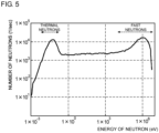
- FIG. 5 illustrates one example of an energy spectrum of neutrons that are emitted from the above-described neutron source 21 and that are not moderated by a moderator (moderating member).
- the horizontal axis indicates an energy (kinetic energy) of the neutron
- the vertical axis indicates the number of neutrons passing through a unit sectional area (cm 2 ) per unit time (second).
- neutrons are classified into fast neutrons, thermal neutrons, and the like, depending on their energies.
- energy ranges of the fast neutron and the thermal neutron are not strictly defined.
- the fast neutron may be a neutron having an energy equal to or higher than 1 ⁇ 10 5 (100 keV) in practice (e.g., in an embodied example), but is not limited to this.
- the thermal neutron may be a neutron having an energy equal to or lower than several tens of milli-electron-volts (e.g., 0.05 eV), but is not limited to this.
- a neutron having an energy equal to or lower than 0.01 eV may belong to the thermal neutrons, or may belong to cold neutrons instead of belonging to the thermal neutrons.
- the resonance scattering energy with respect to 56 Fe belongs to the fast neutrons.
- the neutron source 21 is configured so as to emit, to the cable 5, neutrons including a large number of the fast neutrons.
- the neutron source 21 may be configured so as to emit, to the cable 5, neutrons substantially including only the fast neutrons out of the thermal neutrons and the fast neutrons.
- the emitted neutrons may include epithermal neutrons.
- the fast neutrons constituting the emitted neutrons preferably include a large number of neutrons each having the resonance scattering energy (e.g., the above-described resonance scattering energy with respect to 56 Fe).
- the neutron source 21 may include a thermal neutron shielding member 21g arranged on a path through which neutrons travel from the target 21d to the cable 5.
- the neutron source 21 may emit the neutrons to the cable 5 via the thermal neutron shielding member 21g.
- the neutrons immediately before passing through the thermal neutron shielding member 21g may have the energy spectrum illustrated in FIG. 5 , for example.
- the sectional area (hereinafter, simply referred to also as the neutron beam sectional area) of the neutron beam immediately before being made incident on the cable 5 may have a dimension D1 in the cable longitudinal direction (the vertical direction in FIG. 4 ) and a dimension D2 in a direction (the vertical direction in FIG. 3 ) perpendicular to the cable longitudinal direction, such that the dimension D1 is larger than the dimension D2.
- a shape of the neutron beam sectional area may be, for example, substantially rectangular or substantially elliptical (substantially rectangular in FIG. 4 ).
- the dimension D2 may be equal to or smaller than an outer diameter Dc of the cable 5 (e.g., may be equal to the outer diameter of the cable 5 or equal to an outer diameter of a bundle of the metal wires 11).
- the neutron beam sectional area is preferably within an area of the cable 5 when viewed in a traveling direction of the neutron beam.
- the hatched part is an irradiation region R that is on the outer peripheral surface of the cable 5 and that is irradiated with the neutron beam.
- the neutron detector 22a may be arranged such that in the cable longitudinal direction, a part of the detection surface 23 is positioned within the irradiation region R, and a remaining part of the detection surface 23 is positioned outside the irradiation region R.
- the neutron detector 22a may be arranged such that in the cable longitudinal direction, the entire detection surface 23 is positioned outside the irradiation region R.
- L denotes a length of the part (hereinafter, referred to a non-incident part) that is included in the detection surface 23 and that extends, outside the irradiation region R, continuously in the cable longitudinal direction from a boundary between an outside of the irradiation region R and an inside of the irradiation region R.
- the length L may be equal to or larger than the outer diameter Dc of the cable 5 or be equal to or larger than the outer diameter of the bundle of the metal wires 11 (e.g., L may be equal to or larger than two times, three times, five times, or seven times either of these outer diameters).
- the detection surface 23 includes the non-incident parts positioned on both sides in the cable longitudinal direction and having respective lengths L1 and L2 as the lengths L.
- the following describes an arrangement of the neutron detector 22a in a peripheral direction of the cable 5.
- the neutron detector 22a detects a large number of the target neutrons from this water region. As a result, it is possible to more reliably detect that water exists inside the cable 5.
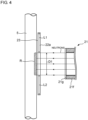
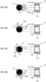
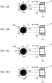
- FIG. 6A corresponds to a part of FIG. 3
- FIG. 6B to FIG. 6D illustrates the cases where a position of the neutron detector 22a is changed from the case of FIG. 6A while positions of the neutron source 21 and the cable 5 are not changed.
- X1 to X4 denote assumed water regions where water exists.
- Arrangement positions for the neutron detector 22a include the following front position, opposite position, and intermediate position.
- the peripheral direction of the cable 5 is referred to simply as the peripheral direction
- a radial direction of the cable 5 is referred to simply as the radial direction.
- the front position is a position that faces the irradiation region R (e.g., a center of the irradiation region R in the peripheral direction) in the radial direction.
- the opposite position is a position that faces, in the radial direction, a part (hereinafter, referred to as an opposite side part) that is on the outer peripheral surface of the cable 5 and that is positioned on an opposite side of the irradiation region R (e.g., the center of the irradiation region R in the peripheral direction).
- the intermediate position is an intermediate position between the front position and the opposite position in the peripheral direction.
- the two intermediate positions are on mutually opposite sides with respect to the cable 5.
- the neutron detector 22a when the neutron detector 22a is arranged at the front position near the water region X1 as illustrated in this drawing, the neutron detector 22a can detect the target neutrons that are derived from the water region X1 and of which number is significantly larger than that in the case where the neutron detector 22a is arranged at either of the opposite position and the intermediate position. Also in each case of the water regions X2 to X4 in FIG. 6B to FIG. 6D , when the neutron detector 22a is arranged at the opposite position or the intermediate position near this water region, the neutron detector 22a can detect the target neutrons that are derived from this water region and of which number is significantly larger than that in each of the other arrangements.
- an arrangement of the neutron detectors 22a may be changed to arrangements such as the respective arrangements in FIG. 6A to FIG. 6D in the peripheral direction, and the inspection may be performed for each of the arrangements.
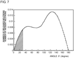
- FIG. 7 illustrates a result of simulation concerning the case where a neutron beam is emitted to a solid cylindrical iron block from a side surface of the iron block, and illustrates the number of the neutrons scattered inside the iron block and released to an outside of the iron block.
- the horizontal axis indicates an angle ⁇ of viewing from a center point in the iron block. This center point is a center point of a part where an extension of the incident neutron beam intersects with an axis of the above-mentioned solid cylinder block.
- the angle ⁇ is the angle made between the incident direction of the neutron beam to the iron block and a direction of the viewing.
- the vertical axis indicates, as a ratio to the number of the incident neutrons, the number of the neutrons scattered inside the iron block so as to be released to an outside of the iron block. More specifically, the vertical axis in FIG. 7 indicates, for the corresponding angle ⁇ , the ratio of the number of the neutrons passing through a minute region existing in the direction of this angle ⁇ when viewed from the center point. This minute region is a part of a surface of a sphere whose center is the center point and whose radius r is the same as a radius of the above-mentioned solid cylinder block. The minute region has an area of 2 ⁇ r 2 sin ⁇ d ⁇ . Concerning FIG. 7 , the number of the released neutrons is normalized by the number of the incident neutrons, and numerical values indicated by the vertical axis are values as an example.
- a significant number of neutrons are scattered inside the iron block so as to be released to a side opposite to an irradiation region of the neutron beam.
- the number of the neutrons released at an angle within 30 degrees from the incident direction is 7.6% of the total number of the scattered and released neutrons.
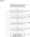
- FIG. 8 is a flowchart illustrating a cable inspection method according to the first embodiment of the present invention.
- This cable inspection method is a method for inspecting the cable 5 for supporting a bridge, and is performed using the above-described cable inspection device 10.
- the cable inspection method includes steps S1 to S4.
- the neutron source 21 and the neutron detector 22a are arranged in relation to the cable 5 (that is in a state of supporting the bridge).
- the neutron source 21 is arranged at a position for emitting neutrons to a desired region (irradiation region) on an outer peripheral surface of the cable 5.
- the neutron detector 22a is arranged, for example, at the above-described front position, the above-described opposite position, or the above-described intermediate position. At this time, the neutron source 21 and the neutron detector 22a may be supported by an unillustrated appropriate support structure or support device.
- the neutron source 21 emits neutrons (e.g., a pulsed neutron beam) to the irradiation region on the outer peripheral surface of the cable 5.
- neutrons e.g., a pulsed neutron beam
- the neutron detection device 22 detects target neutrons released from the cable 5 to an outside of the cable 5 as a result of the step S2, and measures the number of the detected target neutrons.
- the neutron detection device 22 detects the target neutrons released from the cable 5 and incident on the detection surface 23 as a result of the step S2, and measures the number of the detected target neutrons.
- the step S3 may include steps S31 to S33.
- the neutron detector 22a outputs the above-described detection signals for each position on the detection surface 23, and the data generation device 22b generates and outputs detection data that represent, for each position on the detection surface 23, the number of the target neutrons incident on this position.
- the data processing unit 22d generates and outputs difference data that represent, for each position on the detection surface 23, a difference between the number of the incident neutrons in the reference data and the number of the incident neutrons in the detection data output at the step S31.
- the display unit 22e displays, on its screen, the difference data output at the step S32.
- the display unit 22e displays, as the difference data, data such as those illustrated in FIG. 16 described below.
- a position of the neutron detector 22a is changed in the peripheral direction while the position of the neutron source 21 in relation to the cable 5 is kept constant (i.e., the irradiation region is kept constant). Then, the steps S2 and S3 are performed again. The steps S2 to S4 are repeated in this manner so that the steps S2 and S3 are performed for each peripheral-direction position of the neutron detector 22a.
- These peripheral-direction positions may be, for example, the above-described front position, the above-described opposite position, and the above-described two intermediate positions opposite each other with respect to the cable 5.
- Such repeating of the steps S2 to S4 can implement the inspection in which a position of the neutron detector 22a is changed. Thereby, it can be found that water exists near the position of the neutron detector 22a corresponding to the difference data that most strongly indicate existence of water.
- a position of the neutron source 21 in relation to the cable 5 is constant, a position of the neutron source 21 (irradiation region) may be changed in the cable longitudinal direction, and the steps S2 to S4 may be repeated for each of the irradiation regions as described above.
- inspection is preferably performed with a longitudinal end portion of the cable 5 being preferentially set as an irradiation region. This is because a possibility of water existence tends to be higher in the longitudinal end portion of the cable 5 than that in the remaining portions of the cable 5.
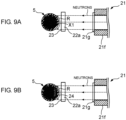
- FIG. 9A and FIG. 9B each illustrate an arrangement of the neutron source 21, the neutron detector 22a, and the cable 5 in inspection of the cable 5 by the cable inspection device 10.
- a position of the neutron detector 22a in each of FIG. 9A and FIG. 9B corresponds to the above-described front position.
- the sound cable 5 containing no water inside is arranged.
- an acrylic plate is arranged inside the cable 5.
- a hydrogen density in acryl is almost the same as that in water, and neutrons easily react with hydrogen. Accordingly, the acrylic plate 24 can be regarded as water.
- Each of the metal wires 11 of the cable 5 used in the experiment example 1 is a steel wire, an outer diameter of a bundle of the steel wires 11 is 100 mm, and this bundle is arranged inside a protective tube 12 made of polyethylene.
- the acrylic plate 24 used in the experiment example 1 has a rectangular parallelepiped shape, a thickness of 5 mm, a dimension (a dimension in a direction perpendicular to the paper surface of the drawing) of 300 mm in the cable longitudinal direction, and a dimension of 50 mm in its width direction.
- the inspection was performed using the cable inspection device 10.
- a neutron beam was emitted to the cable 5 by the neutron source 21, and target neutrons from the cable 5 were detected by the neutron detector 22a.
- the neutron beam was emitted to the cable 5 such that when viewed in an emission direction of the neutron beam to the cable 5, the irradiation region was included in an existence range of the acrylic plate 24 in the longitudinal direction of the cable 5.
- the inspection for each of FIG. 9A and FIG. 9B was performed under the same conditions, except that the acrylic plate 24 was arranged inside the cable 5 in FIG. 9B instead of some of the metal wires 11.
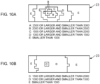
- FIG. 10A and FIG. 10B illustrate results of the inspection for the cases of FIG. 9B and FIG. 9A , respectively.
- the large rectangle represents the two-dimensional detection surface 23 when viewed in the left-right direction in FIG. 9A or 9B .
- the detection surface 23 is a part of the actual detection surface 23 in the longitudinal direction, and a longitudinal-direction range of this part is the same as that of the acrylic plate 24.
- the data in FIG. 10A and FIG. 10B represent the number of the target neutrons incident on the detection surface 23 over a measurement period of 10 minutes, and the measurement start time point is the time when the pulsed neutron beam was emitted to the cable 5.
- the regions A to E on the detection surface 23 are regions that differ from each other in the number of the incident target neutrons per unit area.
- the region A is a region where the number of the incident target neutrons per unit area is approximately equal to or larger than 2500 and smaller than 3000.
- the region B is a region where the number of the incident target neutrons per unit area is approximately equal to or larger than 2000 and smaller than 2500.
- the region C is a region where the number of the incident target neutrons per unit area is approximately equal to or larger than 1500 and smaller than 2000.
- the region D is a region where the number of the incident target neutrons per unit area is approximately equal to or larger than 1000 and smaller than 1500.
- the region E is a region where the number of the incident target neutrons per unit area is approximately smaller than 1000.
- the number of the detected incident target neutrons is substantially larger than that in the case of FIG. 10B where the cable 5 is sound. Accordingly, based on the number of detected incident target neutrons, it can be detected whether water exists inside the cable 5.
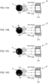
- FIG. 11A to FIG. 11D each illustrate an arrangement of the neutron source 21, the neutron detector 22a, and the cable 5 in inspection of the cable 5 by the cable inspection device 10.
- a position of the neutron detector 22a in each of FIG. 11A to FIG. 11D corresponds to the above-described front position.
- four acrylic plates 24 are stacked inside the cable 5. The position of the four acrylic plates 24 differ among FIG. 11A to FIG. 11D , but positions of the neutron source 21 and the neutron detector 22a are the same for FIG. 11A to FIG. 11D .
- a structure (materials, dimensions, and the like) of the cable 5 used in the experiment example 2 is the same as that of the cable 5 used in the experiment example 1.
- a structure (dimensions, a shape, and the like) of each acrylic plate 24 used in the experiment example 2 is the same as that of the acrylic plate 24 used in the experiment example 1.
- the inspection was performed using the cable inspection device 10.
- a neutron beam was emitted to the cable 5 by the neutron source 21, and target neutrons from the cable 5 were detected by the neutron detector 22a.
- the neutron beam was emitted to the cable 5 such that when viewed in an emission direction of the neutron beam to the cable 5, an irradiation region was included in an existence range of the acrylic plates 24 in the cable longitudinal direction.
- the inspection for each of FIG. 11A to FIG. 11D was performed under the same conditions, except that a position of the four acrylic plates 24 differs among FIG. 11A to FIG. 11D .
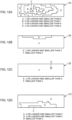
- FIG. 12A to FIG. 12D illustrate results of the inspection for the cases of FIG. 11A to FIG. 11D , respectively.
- the large rectangle represents the two-dimensional detection surface 23 when viewed in the left-right direction in FIG. 11A to FIG. 11D .
- the detection surface 23 is a part of the actual detection surface 23 in the longitudinal direction, and a longitudinal-direction range of this part is the same as that of the acrylic plates 24.
- the data in FIG. 12A to FIG. 12D represent the number of the target neutrons incident on the detection surface 23 over a measurement period of 10 minutes, and the measurement start time point is the time when the pulsed neutron beam was emitted to the cable 5.
- FIG. 12A to FIG. 12D each illustrate a ratio of the number of the incident target neutrons per unit area at each position on the detection surface 23, to a reference value at this position.
- the reference value is the number of the incident target neutrons when the four acrylic plates 24 are not arranged inside the cable 5.
- the reference value is the number of the incident target neutrons at each position on the detection surface 23 in FIG. 9A described above.
- the region A is a region where the ratio is approximately equal to or larger than 7 and smaller than 8
- the region B is a region where the ratio is approximately equal to or larger than 6 and smaller than 7
- the region C is a region where the ratio is approximately equal to or larger than 4 and smaller than 6
- the region D is a region where the ratio is approximately equal to or larger than 2 and smaller than 4.
- the region E is a region where the ratio is approximately equal to or larger than 2 and smaller than 3
- the region F is a region where the ratio is approximately smaller than 2.
- the region C is a region where the ratio is approximately equal to or larger than 4 and smaller than 6
- the region G is a region where the ratio is approximately equal to or larger than 3 and smaller than 4
- the region H is a region where the ratio is approximately smaller than 3.
- FIG. 13A to FIG. 13D each illustrate an arrangement of the neutron source 21, the neutron detector 22a, and the cable 5 in inspection of the cable 5 by the cable inspection device 10.
- a position of the neutron detector 22a in each of FIG. 13A to FIG. 13D corresponds to the above-described opposite position.
- one acrylic plate 24 is arranged inside the cable 5.
- a position of the acrylic plate 24 differs among FIG. 13A to FIG. 13D , but positions of the neutron source 21 and the neutron detector 22a are the same for FIG. 13A to FIG. 13D .
- a structure of the cable 5 used in the experiment example 3 is the same as that of the cable 5 used in the experiment example 1.
- a structure of each acrylic plate 24 used in the experiment example 3 is the same as that of the acrylic plate 24 used in the experiment example 1.
- the inspection was performed using the cable inspection device 10.
- a neutron beam was emitted to the cable 5 by the neutron source 21, and target neutrons from the cable 5 were detected by the neutron detector 22a.
- the neutron beam was emitted to the cable 5 such that when viewed in an emission direction of the neutron beam to the cable 5, an irradiation region was included in an existence range of the acrylic plate 24 in the cable longitudinal direction.
- the inspection for FIG. 13A to FIG. 13D was performed under the same conditions, except that a position of the acrylic plate 24 differs among FIG. 13A to FIG. 13D .
- FIG. 14A to FIG. 14D illustrate results of the inspection for the cases of FIG. 13A to FIG. 13D , respectively.
- the large rectangle represents the two-dimensional detection surface 23 when viewed in the left-right direction in FIG. 13A to FIG. 13D .
- the detection surface 23 is a part of the actual detection surface 23 in the longitudinal direction, and a longitudinal-direction range of this part is the same as that of the acrylic plate 24.
- the data in FIG. 14A to FIG. 14D represent the number of the target neutrons incident on the detection surface 23 over a measurement period of 10 minutes, and the measurement start time point is the time when the pulsed neutron beam was emitted to the cable 5.
- FIG. 14A to FIG. 14D each illustrate a ratio of the number of the incident target neutrons per unit area at each position on the detection surface 23, to a reference value at this position.
- the reference value is the number of target neutrons incident at each position on the detection surface 23 when a plurality of the steel wires 11 are arranged instead of the acrylic plate 24 in FIG. 13A .
- the region A is a region where the ratio is approximately equal to or larger than 1.6 and smaller than 2.0
- the region B is a region where the ratio is approximately equal to or larger than 1.4 and smaller than 1.6
- the region C is a region where the ratio is approximately equal to or larger than 1.0 and smaller than 1.4
- the region D is a region where the ratio is approximately equal to or larger than 1.2 and smaller than 1.4
- the region E is a region where the ratio is approximately equal to or larger than 1.
- the region F is a region where the ratio is approximately equal to or larger than 1.2 and smaller than 1.3
- the region G is a region where the ratio is approximately equal to or larger than 1.1 and smaller than 1.2
- the region H is a region where the ratio is approximately equal to or larger than 1.0 and smaller than 1.1.
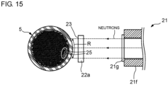
- FIG. 15 illustrates an arrangement of the neutron source 21, the neutron detector 22a, and the cable 5 in the inspection of the cable 5 by the cable inspection device 10.
- a position of the neutron detector 22a in FIG. 15 corresponds to the above-described front position.
- Each of the metal wires 11 of the cable 5 used in the experiment example 4 is a steel wire, an outer diameter of a bundle of the steel wires 11 is 185 mm, and this bundle is arranged inside the protective tube 12 made of polyethylene.
- eight acrylic rods 25 having a diameter of 6 mm and five acrylic rods 25 having a diameter of 1 mm were arranged inside the cable 5 in a region enclosed by the white ellipse as illustrated in FIG. 15 .
- These acrylic rods 25 each have a length of 500 mm, and are arranged at the same longitudinal-direction position inside the cable 5.
- the inspection was performed using the cable inspection device 10.
- a neutron beam was emitted to the cable 5 by the neutron source 21, and target neutrons from the cable 5 were detected by the neutron detector 22a.
- the neutron beam was emitted to the cable 5 such that when viewed in an emission direction of the neutron beam to the cable 5, an irradiation region was included in an existence range of the acrylic rods 25 in the cable longitudinal direction.
- FIG. 16 illustrate a result of the inspection for FIG. 15 .
- the large rectangle represents the two-dimensional detection surface 23 when viewed in the left-right direction in FIG. 15 .
- the detection surface 23 is a part of the actual detection surface 23 in the longitudinal direction, and a longitudinal-direction range of this part is the same as that of the acrylic rods 25.
- the data in FIG. 16 represent the number of thermal neutrons incident on the detection surface 23 over a measurement period of 10 minutes, and the measurement start time point is the time when the pulsed neutron beam was emitted to the cable 5.
- FIG. 16 represents difference data.
- FIG. 16 illustrates a difference between the number of the incident thermal neutrons per unit area at each position on the detection surface 23 and a reference value at this position.
- the reference value is the number of incident thermal neutrons per unit area at each position on the detection surface 23 when no acrylic rods 25 are arranged inside the cable 5.
- the reference value is the number of the incident thermal neutrons when a region of the acrylic rods 25 are filled with a plurality of steel rods in FIG. 15 .
- Concerning the other matters, inspection in the case of determining the reference values was performed under the same conditions as those in the inspection for FIG. 15 .
- the difference at each position is expressed as a ratio to the minimum value of the difference.
- the region A is a region where the ratio is approximately equal to or larger than 1.4 and smaller than 1.7
- the region B is a region where the ratio is approximately equal to or larger than 1.2 and smaller than 1.4
- the region C is a region where the ratio is approximately equal to or larger than 1.0 and smaller than 1.2.
- the neutrons react with the water, and thus, reduce their own energies. For this reason, based on the number of the detected target neutrons corresponding to the neutrons having the reduced energies, it can be determined whether water exists inside the cable 5.
- the neutron source 21 emits, to the cable 5, the neutrons including neutrons each of which has the resonance scattering energy. Thereby, a probability that the neutrons are scattered within the cable 5 becomes higher. Accordingly, a distance by which the neutrons travel inside the cable 5 becomes longer. As a result, the neutrons after being scattered are released from the outer peripheral surface of the cable 5 over a wide range in the peripheral direction and the longitudinal direction of the cable 5. Thus, over a range wider than the irradiation range, it can be inspected whether water exists inside the cable 5.
- a dimension of the detection surface 23 in the cable longitudinal direction may be larger than a dimension of the irradiation area in the cable longitudinal direction.
- a predetermined threshold value it can be determined that water exists at a position inside the cable 5 and near this area (e.g., facing this area).
- FIG. 17 illustrates a configuration example of the cable inspection device 10 according to the second embodiment of the present invention.
- the detection surface 23 of the neutron detector 22a is formed so as to surround an inner space in a peripheral direction of the inner space in which the cable 5 can be arranged.
- the detection surface 23 surrounds the cable 5 in the peripheral direction of the cable 5, in a state where the neutron detector 22a is arranged such that the cable 5 is positioned in the inner space as in FIG. 17 .
- Such a neutron detector 22a may extend so as to make one complete circle in the peripheral direction of the inner space.
- the neutron detector 22a including the detection surface 23 may include a plurality of division portions (two division portions 22a1 and 22a2 in the example of FIG. 17 ) that are divided in the peripheral direction of the inner space. With this configuration, a plurality of the division portions can be arranged so as to surround the cable 5 in the peripheral direction. In this state, a plurality of the division portions may be joined to each other by appropriate coupling means.
- the appropriate coupling means may be, for example, a rope or tape wound on an entire outer periphery of the neutron detector 22 in the peripheral direction, or bolts coupling, to each other, flange portions provided on outer peripheral surfaces of the respective division portions, but are not limited to these.
- each of the division portions 22a1 and 22a2 may be supported by an unillustrated support structure or support device.
- the data generation unit 22b Based on respective detection signals output from the neutron detector 22a, the data generation unit 22b generates detection data that represent, for each position on the detection surface 23 (particularly for each position in the peripheral direction of the cable 5), the number of neutrons incident on this position. The data generation unit 22b outputs the generated detection data.
- the cable inspection method according to the second embodiment of the present invention is performed using the cable inspection device 10 according to the second embodiment, and differs in the below-described matters from the cable inspection method of the first embodiment.
- the neutron source 21 and the neutron detector 22a are arranged in relation to the cable 5.
- the neutron detector 22a is arranged so as to surround the cable 5 as described above with reference to FIG. 17 .
- the step S2 is the same as that in the case of the first embodiment.
- the neutron detector 22a outputs the above-described detection signals for each position on the detection surface 23, and the data generation unit 22b outputs the detection data that represent, for each position on the detection surface 23, the number of the target neutrons incident on this position.
- the data processing unit 22d generates and outputs the difference data that represent, for each position on the detection surface 23, a difference between the number of the incident target neutrons in the reference data and the number of the incident target neutrons in the detection data output at the step S31.
- the step S33 is the same as that in the case of the first embodiment.
- step S4 is omitted, and the steps S2 to S4 are not repeated.
- the neutron detector 22a can be arranged so as to surround the cable 4. Thus, differently from the first embodiment, it becomes unnecessary to change a position of the neutron detector 22a in the peripheral direction at the step S4.
- the present invention is not limited to the above-described embodiments, and can be variously modified within the scope of the technical idea of the present invention.
- the cable inspection device 10 and the cable inspection method do not need to include all of a plurality of the above-described matters, and may include only a part of a plurality of the above-described matters.
- the cable inspection device 10 and the cable inspection method do not need to achieve all of the above-described advantageous effects, and may achieve only a part of the above-described advantageous effects.
- any one of the following modified examples 1 to 3 may be adopted, or two or all of the modified examples 1 to 3 may be adopted in any combination.
- the matters that are not described below may be the same as those in the first embodiment or the second embodiment described above.
- the data processing unit 22d generates and outputs ratio data (processed data) that represent, for each position on the detection surface 23, a ratio between the number of the incident target neutrons in the reference data and the number of the incident target neutrons in the detection data (e.g., a ratio of the number of the incident target neutrons in the detection data to the number of the incident target neutrons in the reference data).
- the data generation unit 22b may generate and output detection data that represent the total number of the target neutrons incident on the entire detection surface 23.
- the reference data may be data concerning the sound cable and representing the total number of the target neutrons incident on the entire detection surface 23, and the data processing unit 22d may generate and output processed data that represent a difference or ratio between the total number in the reference data and the total number in the detection data.
- the neutron source 21 includes the ion source 21a, the acceleration device 21b, the target 21d, and the like in the above description, but does not need to include these constituents.
- the neutron source that emits neutrons to the cable 5 may be a radioisotope (RI) neutron source.
- This RI neutron source may be 252 Cf, for example, but is not limited to this.
Landscapes
- Chemical & Material Sciences (AREA)
- Health & Medical Sciences (AREA)
- Life Sciences & Earth Sciences (AREA)
- General Physics & Mathematics (AREA)
- Physics & Mathematics (AREA)
- Analytical Chemistry (AREA)
- Biochemistry (AREA)
- General Health & Medical Sciences (AREA)
- Immunology (AREA)
- Pathology (AREA)
- Crystallography & Structural Chemistry (AREA)
- Engineering & Computer Science (AREA)
- Food Science & Technology (AREA)
- Medicinal Chemistry (AREA)
- Toxicology (AREA)
- Analysing Materials By The Use Of Radiation (AREA)
Applications Claiming Priority (2)
| Application Number | Priority Date | Filing Date | Title |
|---|---|---|---|
| JP2020106799A JP7560046B2 (ja) | 2020-06-22 | 2020-06-22 | ケーブル検査装置とケーブル検査方法 |
| PCT/JP2021/023242 WO2021261405A1 (fr) | 2020-06-22 | 2021-06-18 | Dispositif d'inspection de câble et procédé d'inspection de câble |
Publications (2)
| Publication Number | Publication Date |
|---|---|
| EP4170330A1 true EP4170330A1 (fr) | 2023-04-26 |
| EP4170330A4 EP4170330A4 (fr) | 2023-12-20 |
Family
ID=79244326
Family Applications (1)
| Application Number | Title | Priority Date | Filing Date |
|---|---|---|---|
| EP21829123.5A Pending EP4170330A4 (fr) | 2020-06-22 | 2021-06-18 | Dispositif d'inspection de câble et procédé d'inspection de câble |
Country Status (4)
| Country | Link |
|---|---|
| US (1) | US12372484B2 (fr) |
| EP (1) | EP4170330A4 (fr) |
| JP (1) | JP7560046B2 (fr) |
| WO (1) | WO2021261405A1 (fr) |
Cited By (1)
| Publication number | Priority date | Publication date | Assignee | Title |
|---|---|---|---|---|
| EP4439056A4 (fr) * | 2021-11-24 | 2025-04-09 | Riken | Dispositif d'observation et procédé d'acquisition d'image de coupe transversale |
Family Cites Families (10)
| Publication number | Priority date | Publication date | Assignee | Title |
|---|---|---|---|---|
| JP2736955B2 (ja) * | 1994-05-13 | 1998-04-08 | 非破壊検査株式会社 | 金属材料中の水素量測定方法及び測定装置 |
| JP4649580B2 (ja) | 2006-09-26 | 2011-03-09 | 独立行政法人 日本原子力研究開発機構 | 複合型廃棄体確認システム |
| JP2010151646A (ja) | 2008-12-25 | 2010-07-08 | Shinko Engineering & Maintenance Co Ltd | 光ファイバケーブル内の水分検出方法および中性子水分計 |
| JP5955101B2 (ja) | 2012-05-28 | 2016-07-20 | 地方独立行政法人北海道立総合研究機構 | ケーブル検査装置 |
| JP5994002B1 (ja) | 2015-09-03 | 2016-09-21 | 新日鉄住金エンジニアリング株式会社 | ケーブル被覆損傷位置検出方法、およびケーブル被覆損傷位置検出装置 |
| JP6712418B2 (ja) * | 2015-09-09 | 2020-06-24 | 国立研究開発法人理化学研究所 | 非破壊検査装置と方法 |
| US11385364B2 (en) * | 2016-10-28 | 2022-07-12 | University Of Florida Research Foundation, Inc. | Portable neutron imaging based non-destructive evaluation |
| NL2017769B1 (en) | 2016-11-11 | 2018-05-24 | Scrapscanner B V | Process and apparatus for scrap metal scanning |
| JP6474070B2 (ja) | 2018-02-19 | 2019-02-27 | 中日本高速道路株式会社 | 斜張橋の斜材点検方法 |
| CN112997102B (zh) * | 2018-06-25 | 2024-09-10 | Kth控股公司 | 辐射检测系统和方法 |
-
2020
- 2020-06-22 JP JP2020106799A patent/JP7560046B2/ja active Active
-
2021
- 2021-06-18 WO PCT/JP2021/023242 patent/WO2021261405A1/fr not_active Ceased
- 2021-06-18 US US18/008,747 patent/US12372484B2/en active Active
- 2021-06-18 EP EP21829123.5A patent/EP4170330A4/fr active Pending
Cited By (1)
| Publication number | Priority date | Publication date | Assignee | Title |
|---|---|---|---|---|
| EP4439056A4 (fr) * | 2021-11-24 | 2025-04-09 | Riken | Dispositif d'observation et procédé d'acquisition d'image de coupe transversale |
Also Published As
| Publication number | Publication date |
|---|---|
| EP4170330A4 (fr) | 2023-12-20 |
| WO2021261405A1 (fr) | 2021-12-30 |
| US20230213462A1 (en) | 2023-07-06 |
| JP2022001849A (ja) | 2022-01-06 |
| JP7560046B2 (ja) | 2024-10-02 |
| US12372484B2 (en) | 2025-07-29 |
Similar Documents
| Publication | Publication Date | Title |
|---|---|---|
| US20100061500A1 (en) | Compact neutron source and moderator | |
| JP7735001B2 (ja) | 非破壊検査方法と装置 | |
| CN103597376B (zh) | 利用射线和中子的安全检查装置 | |
| US20100284504A1 (en) | Device and apparatus for measuring the enrichment profile of a nuclear fuel rod | |
| US10096391B2 (en) | Gamma-ray sensing probe using Cerenkov effect and system for identifying burnup of spent nuclear fuel assembly using the same | |
| US12372484B2 (en) | Cable inspection device and cable inspection method | |
| KR102308130B1 (ko) | 입자가속기를 구비한 중성자투과검사 장치 | |
| US6724852B1 (en) | Fissile interrogation using gamma rays from oxygen | |
| JP5038158B2 (ja) | 中性子束測定システム及び方法 | |
| RU2447520C1 (ru) | Способ измерения интенсивности нейтронного потока | |
| US12259340B2 (en) | Nondestructive inspecting device, and nondestructive inspecting method | |
| CN119395061B (zh) | 夹杂物位置的获取方法及设备 | |
| JP6875265B2 (ja) | 中性子線検出装置 | |
| JP6638065B2 (ja) | 原子炉出力監視装置 | |
| CN111751396A (zh) | 一种机械结构件微结构损伤失效检测分析方法 | |
| US20250027890A1 (en) | Observation device, and cross-sectional image acquisition method | |
| JP2002341045A (ja) | 中性子検出器ユニット | |
| JP2019152497A (ja) | ミュオグラフィを用いる構造物の非破壊検査方法及び装置 | |
| CN117949489A (zh) | 一种核共振荧光检测方法 | |
| Shillington | Sensitivity Study of the Charged Lepton Flavour Violating Mode B+→ K+ τ+ e-At Belle II | |
| Atetalla | The First Harmonic Anisotropy of Charmed Mesons In 200 GeV Au+ Au Collisions | |
| JP2008014816A (ja) | 複合構造物の表層内部に位置する異質物同士の存在状態を精度よく短時間で測定できる非破壊検査方法および装置 | |
| Doll | Measurement of the rare transition b to s-gamma using the complete BABAR data set | |
| Rescigno | The neutrino interaction analysis chain in OPERA | |
| CN110927809A (zh) | 特殊核材料检测装置 |
Legal Events
| Date | Code | Title | Description |
|---|---|---|---|
| STAA | Information on the status of an ep patent application or granted ep patent |
Free format text: STATUS: THE INTERNATIONAL PUBLICATION HAS BEEN MADE |
|
| PUAI | Public reference made under article 153(3) epc to a published international application that has entered the european phase |
Free format text: ORIGINAL CODE: 0009012 |
|
| STAA | Information on the status of an ep patent application or granted ep patent |
Free format text: STATUS: REQUEST FOR EXAMINATION WAS MADE |
|
| 17P | Request for examination filed |
Effective date: 20221212 |
|
| AK | Designated contracting states |
Kind code of ref document: A1 Designated state(s): AL AT BE BG CH CY CZ DE DK EE ES FI FR GB GR HR HU IE IS IT LI LT LU LV MC MK MT NL NO PL PT RO RS SE SI SK SM TR |
|
| P01 | Opt-out of the competence of the unified patent court (upc) registered |
Effective date: 20230523 |
|
| DAV | Request for validation of the european patent (deleted) | ||
| DAX | Request for extension of the european patent (deleted) | ||
| A4 | Supplementary search report drawn up and despatched |
Effective date: 20231117 |
|
| RIC1 | Information provided on ipc code assigned before grant |
Ipc: G01N 33/2045 20190101ALI20231113BHEP Ipc: G01N 23/22 20180101ALI20231113BHEP Ipc: G01N 23/09 20180101AFI20231113BHEP |
|
| STAA | Information on the status of an ep patent application or granted ep patent |
Free format text: STATUS: EXAMINATION IS IN PROGRESS |
|
| 17Q | First examination report despatched |
Effective date: 20250811 |