EP4170536B1 - Datenverarbeitungsverfahren und -vorrichtung sowie speichermedium - Google Patents
Datenverarbeitungsverfahren und -vorrichtung sowie speichermedium Download PDFInfo
- Publication number
- EP4170536B1 EP4170536B1 EP20943904.1A EP20943904A EP4170536B1 EP 4170536 B1 EP4170536 B1 EP 4170536B1 EP 20943904 A EP20943904 A EP 20943904A EP 4170536 B1 EP4170536 B1 EP 4170536B1
- Authority
- EP
- European Patent Office
- Prior art keywords
- child node
- node
- processor
- memory
- data
- Prior art date
- Legal status (The legal status is an assumption and is not a legal conclusion. Google has not performed a legal analysis and makes no representation as to the accuracy of the status listed.)
- Active
Links
Images


Classifications
-
- G—PHYSICS
- G06—COMPUTING OR CALCULATING; COUNTING
- G06F—ELECTRIC DIGITAL DATA PROCESSING
- G06F21/00—Security arrangements for protecting computers, components thereof, programs or data against unauthorised activity
- G06F21/60—Protecting data
- G06F21/64—Protecting data integrity, e.g. using checksums, certificates or signatures
-
- G—PHYSICS
- G06—COMPUTING OR CALCULATING; COUNTING
- G06F—ELECTRIC DIGITAL DATA PROCESSING
- G06F12/00—Accessing, addressing or allocating within memory systems or architectures
- G06F12/02—Addressing or allocation; Relocation
- G06F12/0223—User address space allocation, e.g. contiguous or non contiguous base addressing
- G06F12/023—Free address space management
-
- G—PHYSICS
- G06—COMPUTING OR CALCULATING; COUNTING
- G06F—ELECTRIC DIGITAL DATA PROCESSING
- G06F21/00—Security arrangements for protecting computers, components thereof, programs or data against unauthorised activity
- G06F21/70—Protecting specific internal or peripheral components, in which the protection of a component leads to protection of the entire computer
- G06F21/78—Protecting specific internal or peripheral components, in which the protection of a component leads to protection of the entire computer to assure secure storage of data
-
- G—PHYSICS
- G06—COMPUTING OR CALCULATING; COUNTING
- G06F—ELECTRIC DIGITAL DATA PROCESSING
- G06F2212/00—Indexing scheme relating to accessing, addressing or allocation within memory systems or architectures
- G06F2212/10—Providing a specific technical effect
- G06F2212/1052—Security improvement
Definitions
- This application relates to the field of computer security technologies, and in particular, to a data processing method and device and a storage medium.
- Data integrity is one of three essential points of information security, which means ensuring that information or data is not subjected to tampering without authorization or tampering can be found quickly during information or data transmission, storage, and processing.
- an integrity tree Integrity Tree
- Intel Intel
- SGX software guard extensions
- the integrity tree is used to protect integrity of internal memory data and protect data in an internal memory from replay attacks.
- the integrity tree is stored in a main memory (Main Memory).
- Main Memory main memory
- the integrity tree is loaded into a cache (Cache).
- cache For example, when the processor reads data from the internal memory, the processor reads ciphertext data from the internal memory, and decrypts the ciphertext data.
- the processor reads the integrity tree from the internal memory and verifies integrity of the data by using the integrity tree.
- Embodiments of this application provide a data processing method and device and a storage medium. to resolve problems of high time overheads, slow verification, and excessive storage resources being occupied in a current data integrity verification process. This problem is solved by the subject matter of the independent claims. Further implementation forms are provided in the dependent claims.
- an embodiment of this application provides a data processing method, applied to a data processing device.
- the data processing device includes a processor and a memory
- the processor includes a cache and a register.
- An integrity tree for data integrity verification includes a plurality of root nodes and a plurality of child nodes, the plurality of root nodes are stored in a form of a decompressed state in the register of the processor, and the plurality of child nodes are stored in a form of a compressed state in the memory.
- the cache of the processor caches child nodes that are previously read from the memory, and the read child nodes are stored in the form of the decompressed state in the cache of the processor.
- a data processing process in this embodiment of this application specifically includes: obtaining a first child node in the compressed state from the memory in response to a read request for target data when the first child node is not detected in the processor, for example, when the first child node is not detected in the cache of the processor, where the first child node is a child node that is in the integrity tree and that is related to the target data; and decompressing the first child node in the compressed state, and caching the decompressed first child node into the processor, where the first child node is used for integrity verification on the target data.
- the root nodes of the integrity tree and the child nodes cached in the processor are stored in the form of the decompressed state in the processor, which makes it convenient for the processor to perform data integrity verification by using the integrity tree nodes in the decompressed state.
- the child nodes of the integrity tree are stored in the form of the compressed state in the memory, so that storage space of the memory can be saved, storage space overheads of the memory can be reduced, and sizes of the child nodes can be effectively reduced.
- the processor obtains a first child node in a compressed state from the memory in response to a read request for target data when the first child node is not verified in the processor, decompresses the first child node in the compressed state, and caches the decompressed first child node into the processor, so that the processor performs integrity verification on the target data by using the first child node. Because a data amount of the first child node in the compressed state is small, the processor can quickly read the first child node in the compressed state from the memory for integrity verification on the target data, thereby reducing time overheads of data integrity verification, and improving an integrity verification speed.
- a process of removing a cached child node includes: obtaining a to-be-removed second child node in the processor when it is detected that a quantity of child nodes in the processor reaches a preset value; and compressing the to-be-removed second child node when it is detected that the to-be-removed second child node is changed, and replacing a second child node in the memory with the compressed second child node.
- the compressing the to-be-removed second child node includes the following two cases:
- a MAC of the second child node is related to the values of the counters of the second child node, in Case 2, when the values of the counters of the to-be-removed second child node are changed, the MAC of the second child node is also changed. Therefore, the MAC of the second child node needs to be re-determined based on reset values of the counters in the second child node, and the re-determined MAC is written into the memory.
- a branching factor of the integrity tree in this embodiment of this application is a preset parameter, and the preset parameter is a positive integer greater than 8 in exponential multiples of 2.
- a current common branching factor of the integrity tree is 8, while the branching factor of the integrity tree in this embodiment of this application is greater than 8, for example, 16 or 32, so that a quantity of layers of the integrity tree can be reduced, and a quantity of times of accessing the integrity tree by the processor can be reduced, thereby improving a data integrity verification speed.
- the integrity tree maintains 16 GB storage space.
- the memory needs to be accessed 12 times, which results in high time overheads of integrity verification and a slow verification speed.
- the memory needs to be accessed only seven times, which effectively reduces a quantity of times of accessing the integrity tree by the processor, thereby reducing time overheads of integrity verification, and improving an integrity verification speed.
- At least two threads may be used to perform parallel decompression on the first child node; and/or when the second child node is compressed, at least two threads may be used to perform parallel compression on the second child node.
- an embodiment of this application provides a data processing device, including a memory and a processor.
- the memory is configured to store data.
- the processor is configured to perform read/write access on the data stored in the memory.
- the processor is specifically configured to: obtain a first child node in a compressed state from the memory in response to a read request for target data when the first child node is not detected in the processor, where the first child node is a child node that is in an integrity tree and that is related to the target data, the integrity tree includes a plurality of root nodes and a plurality of child nodes, the plurality of child nodes are stored in the compressed state in the memory, and the plurality of root nodes are stored in a decompressed state in the processor; and decompress the first child node in the compressed state, and cache the decompressed first child node into the processor, where the first child node is used for integrity verification on the target data.
- the root nodes of the integrity tree and child nodes cached in the processor are stored in a form of the decompressed state in the processor, which makes it convenient for the processor to perform data integrity verification by using the integrity tree nodes in the decompressed state.
- the child nodes of the integrity tree are stored in the compressed state in the memory, so that storage space of the memory can be saved, storage space overheads of the memory can be reduced, and sizes of the child nodes can be effectively reduced.
- the processor obtains a first child node in a compressed state from the memory in response to a read request for target data when the first child node is not verified in the processor, decompresses the first child node in the compressed state, and caches the decompressed first child node into the processor, so that the processor performs integrity verification on the target data by using the first child node. Because a data amount of the first child node in the compressed state is small, the processor can quickly read the first child node in the compressed state from the memory for integrity verification on the target data, thereby reducing time overheads of data integrity verification, and improving an integrity verification speed.
- the processor is specifically configured to: obtain a to-be-removed second child node in the processor when it is detected that a quantity of child nodes in the processor reaches a preset value; and compress the to-be-removed second child node when it is detected that the to-be-removed second child node is changed, and replace a second child node in the memory with the compressed second child node.
- the processor is specifically configured to: pre-compress the to-be-removed second child node, and when a size of the pre-compressed second child node is greater than a size of a minimum storage unit of the memory, add a first value to a value of an overflow counter of the second child node, set a value of each sub-counter of the second child node to a second value, and re-compress the reset second child node.
- the first value is a positive number greater than 0, and the second value is a positive number. For example, the first value is 1, and/or the second value is 0.
- the processor is specifically configured to: when the value of each sub-counter of the second child node is set to the second value, re-determine a message authentication code MAC of the second child node; and write the re-determined MAC into the memory.
- a branching factor of the integrity tree is a preset parameter
- the preset parameter is a positive integer greater than 8 in exponential multiples of 2.
- the preset parameter is 16 or 32.
- the processor is specifically configured to: perform parallel decompression on the first child node by using at least two threads; and/or perform parallel compression on the to-be-removed second child node by using at least two threads.
- an embodiment of this application provides a computer program product.
- the program product includes a computer program, the computer program is stored in a readable storage medium, at least one processor of a communications device may read the computer program from the readable storage medium, and the at least one processor executes the computer program, to enable the communications device to perform the data processing method according to the first aspect.
- the processor decompresses the first child node in the compressed state, and caches the decompressed first child node into the processor for integrity verification on the target data.
- the root nodes of the integrity tree are stored in a form of the decompressed state in the processor, which makes it convenient for the processor to perform data integrity verification by using the root nodes in the decompressed state.
- the child nodes of the integrity tree are stored in a form of the compressed state in the memory, so that storage space of the memory can be saved, storage space overheads of the memory can be reduced, and sizes of the child nodes can be effectively reduced, so that the processor can quickly read the child nodes in the compressed state from the memory for data integrity verification, thereby reducing time overheads of data integrity verification, and improving an integrity verification speed.
- B corresponding to A indicates that B is associated with A.
- B may be determined based on A.
- determining B based on A does not mean that B is determined based on only A.
- B may alternatively be determined based on A and/or other information.
- the term "a plurality of” as used herein means two or more than two.
- the term “and/or” in this specification describes only an association relationship for describing associated objects and represents that three relationships may exist. For example, A and/or B may represent the following three cases: Only A exists, both A and B exist, and only B exists.
- the character "/" as used herein indicates an "or” relationship between associated objects. In a formula, the character "/” indicates a "divide” relationship between associated objects.
- a replay attack means that an attacker records data and a MAC value at a time point T1, and then replays, at a time point T2, the data and the MAC value that are recorded at the time point T1, to attempt to modify data at the time point T2 into the data at the time point T1.
- An integrity tree is a data structure for protecting integrity of a memory, which is a tree structure and includes a plurality of integrity tree nodes.
- the integrity tree is characterized in that integrity of local data can be quickly verified, and is widely applied to scenarios including Bitcoin, Android phone system partitions, and the like.
- a branching factor is a quantity of child nodes included by each node in an integrity tree. For example, if each node in an integrity tree includes eight child nodes, a branching factor of the integrity tree is 8.
- the integrity tree has various variations. The following describes a common integrity tree, as shown in FIG. 1 .
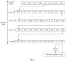
- FIG. 1 is a schematic diagram of a structure of an integrity tree according to an embodiment of this application.
- the integrity tree includes five layers, layers are connected by specific dependencies, and a branching factor is 8, that is, each node includes eight child nodes.
- n37, n36, ..., and n30 are root nodes.
- n20, n21, ..., and n27 are eight child nodes of the root node n33, and are located at a layer 3.
- n10, n11, ..., and n17 are child nodes of the node n20, and are located at a layer 2.
- n00, n01, ..., and n07 are child nodes of the node n10, and are located at a layer 1.
- v0, v1, ..., and v7 are leaf nodes of the child node n00, and are located at a layer 0.
- a storage area of a memory is divided into a plurality of data blocks, and one leaf node corresponds to one data block, and is used to maintain integrity of data in the data block.
- each node in FIG. 1 includes eight counters and one tag (Tag, T for short).
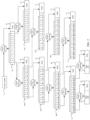
- FIG. 2 is a schematic diagram of a data structure of a counter integrity tree according to an embodiment of this application.
- the tag of each node is a message authentication code (MAC).
- MAC message authentication code
- the root node n33 is used as an example.
- a root counter corresponding to the root node n33 is a counter 11, the root node n33 includes eight counters and a MAC 10, the eight counters are respectively C0 to C7, and the MAC 10 is calculated by using a MAC function based on the root counter 11 and the eight counters C0 to C7 of the root node n33.
- the eight counters of the root node n33 respectively correspond to the eight child nodes n20 to n27 of the root node n33 one by one.
- the node n20 corresponds to the counter C0 of the root node n33
- the node n21 corresponds to the counter C1 of the root node n33
- the node n27 corresponds to the counter C7 of the root node n33.
- Each of the child nodes n20 to n27 includes eight counters and one MAC.
- the child node n20 includes eight counters C00 to C07 and a MAC 20.
- the MAC 20 is calculated by using the MAC function based on the counter C0 of the root node n33 and the eight counters C00 to C07 of the child node n20.
- a MAC 27 of the child node n27 is calculated by using the MAC function based on the counter C7 of the root node n33 and eight counters C70 to C77 of the child node n27.
- a MAC 30 of the child node n10 is calculated by using the MAC function based on the counter C00 of the node n20 and eight counters C000 to C007 of the node n10
- a MAC 37 of the child node n17 is calculated by using the MAC function based on the counter C07 of the node n20 and eight counters C070 to C077 of the node n17
- a MAC 40 of the child node n00 is calculated by using the MAC function based on the counter C000 of the node n10 and eight counters C0000 to C0007 of the node n00
- a MAC 47 of the child node n07 is calculated by using the MAC function based on the counter C007 of the node
- each leaf node includes eight counters and one MAC.
- the leaf node v0 is used as an example.
- the leaf node v0 includes eight counters C00000 to C00007 and a MAC 50.
- the MAC 50 is calculated by using the MAC function based on the counter C0000 of the child node n00 and the eight counters C00000 to C00007 of the leaf node v0.
- the eight counters of the leaf node v0 respectively correspond to eight data blocks in the memory, and each data block corresponds to one MAC.
- a MAC 60 of a data block 70 is calculated by using the MAC function based on the counter C00000 and data 000 in the data block 70
- a MAC 67 of a data block 77 is calculated by using the MAC function based on the counter C00007 and data 007 in the data block 77.
- a MAC for verifying integrity of data in a data block is maintained by a leaf node corresponding to the data block
- a MAC for verifying integrity of the leaf node is maintained by a parent node of the leaf node
- integrity of the parent node may be maintained by using another parent node in the tree, and the same goes on until a root node.
- the data 000 in the data block 70 is read.
- verification is performed on the MAC 60 of the data block 70.
- the counter C00000 in the leaf node v0 is read, a MAC 1 is calculated by using the MAC function based on the counter C00000 and the data 000, and matching is performed between the calculated MAC 1 and the MAC 60 stored in the data block 70. If the stored MAC 60 does not match the calculated MAC 1, it indicates that the data 000 is tampered with. If the stored MAC 60 matches the calculated MAC 1, verification is further performed on integrity of the leaf node v0.
- a parent node (that is, the node n00) of the leaf node v0 is read, a calculated MAC of the leaf node v0 is calculated by using the MAC function based on a counter (that is, the counter C0000) corresponding to the leaf node v0 in the node n00 and the eight counters of the leaf node v0, and matching is performed between the calculated MAC of the leaf node v0 and the stored MAC of the leaf node v0. If the stored MAC of the leaf node v0 does not match the calculated MAC of the leaf node v0, it indicates that the leaf node v0 is tampered with, and integrity verification on the data 000 fails.
- the storage MAC of the leaf node v0 matches the calculated MAC of the leaf node v0, verification is further performed on integrity of the parent node (that is, the node n00) of the leaf node v0. The same goes on until verification on the root node n33. If it is verified that the stored MAC of the root node n33 matches a calculated MAC of the root node n33, it indicates that the data 000 is not tampered with.
- each time data is written into a data block a corresponding counter in the integrity tree is incremented or updated. For example, when data is written into the data block 70, and the data in the data block 70 is updated, the counter C00000 in the leaf node v0 corresponding to the data block 70 is incremented, for example, + 1.
- the increment of the counter C00000 in the leaf node v0 triggers the MAC of the leaf node v0 to be recalculated, the recalculation of the MAC of the leaf node v0 triggers the counter (that is, the counter C0000) in the parent node n00 of the leaf node v0 to be incremented, and the same goes on until the MAC of the root node is updated.
- a MAC of a data block and corresponding data are stored in a same cache line.
- the MAC of the data block and the corresponding data may be stored separately.
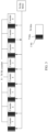
- FIG. 3 is a schematic diagram of a data structure of a node in an integrity tree.
- the MAC of the node may be divided into a plurality of parts to be stored separately.
- the MAC of the node is divided into eight equal parts, respectively stored together with eight counters of the node in a one-to-one correspondence. Each counter occupies 56 bits.
- FIG. 3 shows a MAC with a size of 56 bits
- the 56-bit MAC is divided into eight equal parts, each part is 7 bits and stored in storage space of 8 bits.
- the size of the MAC includes but is not limited to 56 bits.
- the MAC may not be divided into equal parts for storage.
- the MAC function in FIG. 2 may be a unidirectional cryptographic function such as AES-GCM or SHA-256.
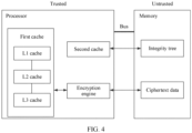
- FIG. 4 is a schematic diagram of an application scenario according to an embodiment of this application.
- the application scenario includes a processor and a memory.
- the processor is trusted, and the memory is untrusted, that is, data in the processor cannot be attacked or tampered with by an attacker, while data in the memory may be arbitrarily attacked or tampered with by an attacker. Therefore, to prevent an attacker from reading the data in the memory, the processor needs to encrypt the data in the memory, so that the attacker cannot read the data in the memory.
- the processor needs to perform integrity verification on the data.
- the processor first queries, in the first cache, whether to-be-read target data is cached, and directly reads the target data from the first cache if the first cache caches the target data. If the target data is not found in the first cache, the target data is read from the memory. Specifically, ciphertext data of the target data is read from the memory, and is stored in the first cache after decrypted.
- the processor queries, in the second cache, whether an integrity tree node corresponding to the target data exists. If the integrity tree node exists, the processor verifies integrity of the target data by using the integrity tree node. If the processor does not find, in the second cache, the integrity tree node corresponding to the target data, the processor reads, from the memory, the integrity tree node corresponding to the target data, for example, a node 1, and calculates a MAC of the target data by using the node 1. If the calculated MAC matches a stored MAC of the target data, verification is further performed on integrity of the node 1, and the same goes on until verification on a corresponding root node.
- integrity tree nodes need to be read from the memory a plurality of times. For example, as shown in FIG. 1 and FIG. 2 , when verification is performed on integrity of target data, integrity of a leaf node corresponding to the target data needs to be verified. When verification is performed on integrity of the leaf node, integrity of a node that is at the layer 1 and that corresponds to the leaf node needs to be verified. When verification is performed on integrity of the node at the layer 1, integrity of a corresponding node at the layer 2 needs to be verified, and so on. A quantity of times of verification that needs to be performed is equal to a quantity of layers of the integrity tree.
- an integrity tree is stored in a form of a compressed state in a memory, so that storage space of the memory can be effectively saved, and storage space overheads of the memory can be reduced.
- a processor reads the integrity tree in the compressed state from the memory. Because a data amount of the integrity tree in the compressed state is small, a speed at which the processor reads the integrity tree from the memory is improved, thereby reducing time overheads of data integrity verification, and improving an integrity verification speed.
- FIG. 5 is a schematic diagram of a system architecture according to an embodiment of this application.
- the system architecture includes a processor and a memory.
- the processor is trusted, and the memory is untrusted. That is, data in the processor is difficult to be tampered with by an attacker. Therefore, an edge of the processor may be used as a trust boundary. Any data that crosses the trust boundary may be tampered with. For example, data in the memory or data on a physical channel between the memory and the processor may be intercepted or tampered with.
- the processor is in communications connection to the memory by using a bus, for example, in communications connection by using a Bus
- the processor stores a root node of an integrity tree.
- the processor may include one or more registers, and the root node of the integrity tree may be stored in any one of the one or more registers.
- the root node of the integrity tree is stored in a form of a decompressed state in the processor, so that the processor can quickly read the root node for integrity verification.
- the root nodes n30 to n37 of the integrity tree shown in FIG. 1 are kept stored in the form of the decompressed state in the processor, and are not lost when powered off.
- the root node may be used to perform integrity verification on a child node of the root node.
- the root node n33 is used to perform integrity verification on the child nodes n20 to n27 of the root node. Integrity verification on the child node n20 is used as an example.
- the processor reads the counters and the MAC of the node n20 from the memory.
- the node n20 corresponds to a counter in the node n33, for example, a counter 1.
- a MAC of the node n20 may be calculated by using a MAC function based on the counter 1 and the counters of the node n20, and matching is performed between the calculated MAC and the MAC read from the memory. If they match, it is determined that integrity verification on the node n20 succeeds. If they do not match, it indicates that integrity verification on the node n20 fails.
- the root node of the integrity tree is stored in the form of the decompressed state in the processor, so that the processor can quickly read the root node for data integrity verification.
- the processor is trusted, storing the root node into the processor can prevent an attacker from reading or tampering with the root node, thereby ensuring reliability and accuracy of data integrity verification.
- the processor further includes a first cache.
- the first cache may include a plurality of levels of caches, for example, including an L1 cache, an L2 cache, and an L3 cache.
- the first cache is configured to cache data, for example, configured to cache data read from the memory.
- the data in the first cache is data on which integrity verification succeeds.
- the processor first queries the first cache for the target data. Specifically, the processor queries the L1 cache for the target data, queries the L2 cache for the target data if the target data is not found in the L1 cache, and queries the L3 cache for the target data if the target data is not found in the L2 cache. After finding the target data in the first cache, the processor directly returns the found target data.
- the processor does not find the target data in the first cache, the processor reads the target data from the memory, and performs integrity verification on the target data.
- the processor further includes a second cache.
- the second cache is configured to cache a child node, read from the memory, of the integrity tree. Specifically, the processor reads a child node, in a compressed state, of the integrity tree from the memory, decompresses the child node in the compressed state, and then caches the child node into the second cache for data integrity verification. That is, the second cache caches one or more child nodes of the integrity tree that are read during last integrity verification. Therefore, during current integrity verification, to improve an integrity verification speed, the processor first queries the second cache for a required child node, for example, a node 1. If the node 1 is found in the second cache, the node 1 is directly used to perform integrity verification without reading from the memory, thereby improving the integrity verification speed.
- the second cache caches the leaf node v0, the node n16, and the node n22.
- the processor reads the data 000 in the data block 70 and the MAC 60 corresponding to the data 000 from the memory, and then performs integrity verification on the data 000.
- the processor determines, based on a correspondence between a data block and a leaf node, that the data block 70 corresponds to the leaf node v00.
- the processor queries, in the second cache, whether the leaf node v00 exists. If the leaf node v00 is found in the second cache, the processor calculates, by using the MAC function based on the counters C00000 to C00007 of the leaf node v00 and the read data 000, a MAC corresponding to the data 000, denoted as a MAC 6. The processor performs matching between the calculated MAC 6 and the MAC 60 read from the memory. If the MAC 6 matches the MAC 60, it indicates that the data 000 is not tampered with, and integrity verification succeeds, and integrity verification does not need to be further performed on the leaf node v00.
- the processor If the processor does not find the leaf node v00 in the second cache, the processor reads the leaf node v00 from the memory. According to the foregoing method, it is determined whether a calculated MAC 6 matches the MAC 60 read from the memory, and if they match, a parent node of the leaf node v00 is read from the memory to verify integrity of the leaf node v00, and the same goes on until a root node.
- the processor further includes a memory encryption engine (memory encryption engine, MEE).
- MEE memory encryption engine
- the MEE is configured to encrypt a plaintext based on a counter, and further configured to decrypt a ciphertext read from the memory. This can prevent a malicious observer from reading data in the memory.
- An encryption key for encryption and decryption may be stored in the processor, for example, stored in a register in the processor.
- An encryption or decryption method used by the memory encryption engine is not limited in this embodiment of this application.
- the processor further includes a compression algorithm.
- the processor compresses an integrity tree node by using the compression algorithm, and stores a compressed integrity tree node into the memory.
- the processor decompresses the integrity tree node in the compressed state by using the compression algorithm, and caches the decompressed integrity tree node into the second cache.
- the memory includes ciphertext data.
- the ciphertext data is data encrypted by the memory encryption engine.
- the processor controls the memory encryption engine to encrypt plaintext data to obtain ciphertext data, and stores the ciphertext data into the memory.
- the ciphertext data cannot be decrypted after read by an attacker, thereby preventing a malicious observer from reading data in the memory.
- the memory further includes plaintext data.
- the plaintext data is data unencrypted, and may be arbitrarily read by an attacker.
- the memory further includes all nodes except the root node in the integrity tree.
- the nodes except the root node in the integrity tree are collectively referred to as child nodes.
- the child nodes in the integrity tree are stored in a form of the compressed state. In this way, a size of the integrity tree can be reduced, to save storage space of the memory.
- the processor can quickly read the child nodes in the compressed state for integrity verification, thereby reducing time overheads of integrity verification, and improving an integrity verification speed.
- the processor in this embodiment of this application may be one processor element, or may be a general term of a plurality of processor elements.
- the processor may be a central processing unit (central processing unit, CPU), or an application specific integrated circuit (application specific integrated circuit, ASIC), or may be configured as one or more integrated circuits implementing this embodiment of this application, for example, one or more microprocessors (digital signal processor, DSP), or one or more field programmable gate array (field programmable gate array, FPGA).
- the memory in this embodiment of this application may be an internal memory, or any usable medium that can be accessed by a computer, or a data storage device such as a server or a data center that integrates one or more usable mediums.
- the usable medium may be a magnetic medium (for example, a floppy disk, a hard disk, or a magnetic tape), an optical medium (for example, a DVD), a semiconductor medium (for example, a solid state disk solid state disk (SSD)), or the like.
- FIG. 6 is a schematic flowchart of a data processing method according to an embodiment of this application. As shown in FIG. 6 , the method in this embodiment of this application includes the following steps.
- the first child node is a child node that is in an integrity tree and that is related to the target data.
- the first child node may be a leaf node corresponding to the target data.
- the target data is the data 000.
- the data 000 is stored in the data block 70.
- the data block 70 corresponds to the leaf node v0 in the integrity tree. Therefore, the first child node corresponding to the data 000 may be the leaf node v0.
- the first child node may alternatively be a parent node of the leaf node corresponding to the target data. Still referring to FIG. 2 , it is assumed that the target data is the data 000.
- a leaf node corresponding to the data 000 is the node v0, and a parent node corresponding to the leaf node v0 is the node n00. Therefore, the first child node corresponding to the data 000 may alternatively be the node n00.
- the first child node corresponding to the target data may alternatively be a parent node of the parent node of the leaf node corresponding to the target data. Still referring to FIG. 2 , it is assumed that the target data is the data 000.
- the parent node of the leaf node corresponding to the data 000 is the node n00, and a parent node corresponding to the node n00 is n10.
- the first child node corresponding to the target data may alternatively be the node n10, and so on. That is, the first child node in this embodiment of this application is any child node that is in the integrity tree and that is related to an integrity verification process of the target data.
- the child node of the integrity tree is a node in the integrity tree other than a root node.
- the integrity tree includes a plurality of root nodes and a plurality of child nodes.
- the integrity tree shown in FIG. 1 includes a total of eight root nodes n30 to n37, and includes four layers of child nodes. Each node includes eight child nodes. Therefore, the layer 3 includes 64 child nodes, the layer 2 includes 512 child nodes, the layer 1 includes 4096 child nodes, and the layer 0 includes 32768 leaf nodes.
- the integrity tree in this embodiment of this application includes but is not limited to that shown in FIG. 1
- a branching factor of the integrity tree in this embodiment of this application includes but is not limited to 8
- a quantity of layers of the integrity tree includes but is not limited to 5, and bits occupied by nodes may be the same or different.
- the branching factor of the integrity tree in this embodiment of this application is a preset parameter, and the preset parameter is a positive integer greater than 8 in exponential multiples of 2.
- the preset parameter is b
- a current common branching factor of the integrity tree is 8, while the branching factor of the integrity tree in this embodiment of this application is greater than 8, for example, 16 or 32, so that a quantity of layers of the integrity tree can be reduced, and a quantity of times of accessing the integrity tree by the processor can be reduced, thereby improving a data integrity verification speed.
- the integrity tree maintains 16 GB storage space.
- the memory needs to be accessed 12 times, which results in high time overheads of integrity verification and a slow verification speed.
- the memory needs to be accessed only seven times, which effectively reduces a quantity of times of accessing the integrity tree by the processor, thereby reducing high time overheads of integrity verification, and improving an integrity verification speed.
- the processor may determine the branching factor of the integrity tree based on a size of the memory and/or access of the processor to the memory. For example, when storage space of the memory is relatively small, or the processor accesses the storage space of the memory unevenly, the processor selects a relatively small branching factor of the integrity tree, for example, selects 16 as the branching factor of the integrity tree. For another example, if the storage space of the memory is relatively large, and the processor accesses the storage space of the memory relatively evenly, the processor selects a relatively large branching factor of the integrity tree, for example, selects 32 or 54 as the branching factor of the integrity tree.
- the root nodes of the integrity tree are stored in a form of a decompressed state in the processor, to ensure security of the root nodes, and prevent an attacker from tampering with the root nodes, because data integrity verification cannot be performed by using the integrity tree if the root nodes are tampered with.
- the MEE can quickly read the root nodes for integrity verification, thereby improving an integrity verification speed. Because storage space of the processor is limited, and the entire integrity tree cannot be stored, the child nodes in the integrity tree other than the root nodes are stored in the memory.
- the plurality of child nodes of the integrity tree are stored in a form of the compressed state in the memory.
- the processor reads child nodes of the integrity tree from the memory a plurality of times.
- the child nodes of the integrity tree are stored in the form of the compressed state in the memory, sizes of the child nodes of the integrity tree are effectively reduced, so that the processor can quickly read the child nodes in the compressed state for integrity verification, thereby reducing time overheads of integrity verification, and improving an integrity verification speed.
- each node includes 16 child nodes.
- Each node includes one overflow counter (overflow counter), 16 sub-counters (sub-counter), and one MAC.
- Each sub-counter occupies 40 bits
- the MAC and the overflow counter each occupy 56 bits
- Each node has a same size, and therefore has a same compression manner.
- one node for example, a node 1, is used as an example to describe a node compression process, to which reference may be made for another node.
- a data structure of the node 1 is shown in Table 1: Table 1 Size (bits) 56 56 40 40 40 ... 40 Name MAC Overflow counter Sub-counter 1 Sub-counter 2 Sub-counter 3 ... Sub-counter 16 Value D1 B1 A1 A2 A3 ... A16
- one node includes one overflow counter and 16 sub-counters
- the overflow counter occupies 56 bits, indicating that the overflow counter may represent an integer from 0 to 2 56 -1
- one sub-counter occupies 40 bits, indicating that one sub-counter may represent an integer from 0 to 2 40 -1. If 0 is represented by 40 bits, its actual stored value is 0000000000 0000000000 0000000000 0000000000. If 1 is represented by 40 bits, its actual stored value is 0000000000 0000000000 0000000000 000001. However, because values of most sub-counters are relatively small, there are a large quantity of 0s, and storage space is wasted. In addition, because a node length of 40 bits is relatively long, it is time-consuming for the processor to read a node from the memory, thereby affecting data integrity verification efficiency.
- the node 1 shown in Table 1 is compressed.
- a method for compressing the node 1 includes but is not limited to the following several manners:
- Manner 1 The node 1 shown in Table 1 is compressed in an equal-length compression manner, that is, a length of each sub-counter in the node 1 is compressed from 40 bits to a first preset value.
- the first preset value is any even number less than 40 bits and greater than 0.
- the first preset value is 16 bits
- a decimal value of the value A1 of the sub-counter 1 is 1, and a binary value of corresponding 40 bits is 0000000000 0000000000 0000000000 0000000001.
- the value A1 of the sub-counter 1 is compressed from the 40 bits to 16 bits, and a binary value of the 16 bits corresponding to A1 is 000000 0000000001.
- a decimal value of the value A2 of the sub-counter 2 is 555, and a binary value of corresponding 40 bits is 00000000000 0000000000 0000000000 0000110111.
- the value A2 of the sub-counter 2 is compressed from the 40 bits to 16 bits, and a binary value of the 16 bits corresponding to A2 is 000000 0000110111.
- each sub-counter of the node 1 in Table 1 may be compressed from 40 bits to 16 bits, as shown in Table 2: Table 2 Size (bits) 56 56 16 16 16 ... 16 Name MAC Overflow counter Sub-counter 1 Sub-counter 2 Sub-counter 3 ... Sub-counter 16 Value D1 B1 A1 A2 A3 ... A16
- the sub-counters of the node 1 are compressed, while the MAC and the overflow counter of the node 1 are not compressed. In this way, the MAC or the overflow counter of the node 1 can be prevented from overflowing.
- the MAC and/or the overflow counter of the node 1 is compressed, that is, a value of the MAC and/or the overflow counter of the node 1 is compressed from 56 bits to 16 bits, as shown in Table 3: Table 3 Size (bits) 16 16 16 16 16 ... 16 Name MAC Overflow counter Sub-counter 1 Sub-counter 2 Sub-counter 3 ... Sub-counter 16 Value D1 B1 A1 A2 A3 ... A16
- the MAC and the overflow counter of the node 1 are compressed from 56 bits to 16 bits, to further reduce the data amount of the node 1, so that when the processor reads the node 1 in the compressed state from the memory, a reading speed of the processor is further improved, thereby further increases the data integrity verification speed.
- a minimum storage unit of the internal memory is a cache line (cache line).
- a size of one cache line is usually 512 bits or 64 bytes. That is, when a compressed second child node is stored in the internal memory, a size of the compressed second child node cannot be greater than 512 bits or 64 bytes.
- a minimum storage unit of the hard disk is a sector (sector) or a block (block). One sector or block is usually 4096 bytes. That is, when a compressed second child node is stored in the hard disk, a size of the compressed second child node cannot be greater than 4096 bytes.
- the value of each sub-counter of the node 1 is set to a second value. For example, the second value is 0.
- Table 4 Size (bits) 56 56 16 16 16 ... 16 Name MAC Overflow counter
- Sub-counter 1 Sub-counter 2
- Sub-counter 3 ...
- Sub-counter 16 Value D2 B2 C C C ... C
- C is the second value
- D2 is a re-determined MAC value of the node 1.
- the MAC value D2 of the node 1 is recalculated by using a MAC function based on a value of a counter of a parent node corresponding to the node 1, and the value B2 of the overflow counter and the values C of the sub-counter 1 to the sub-counter 16 in Table 4.
- the first preset value may be specified by a user, or may be determined by the processor.
- a manner in which the processor determines the first preset value includes but is not limited to the following several examples:
- Example 1 The processor determines the first preset value based on the size of the minimum storage unit of the memory and the data structure of the child node in the decompressed state.
- the memory is an internal memory.
- a minimum storage unit of the internal memory is a cache line (cache line), a size of the cache line is 512 bits or 64 bytes, and a size of a child node stored in the memory cannot exceed a size of one cache line.
- the node 1 in Table 1 is used as an example.
- the node 1 includes one overflow counter (overflow counter), 16 sub-counters (sub-counter), and one MAC, and the MAC and the overflow counter each occupy 56 bits.
- the MAC and the overflow counter of the node 1 are not compressed, each still occupies 56 bits in one cache line. In this way, remaining 400 bits of the one cache line are allocated to the 16 sub-counters (sub-counter), and then it is determined that the first preset value cannot exceed 25 bits. If the MAC and the overflow counter of the node 1 are also compressed, the 512 bits are equally divided into 18 parts, and each part occupies 28 bits. Therefore, the first preset value cannot exceed 28 bits.
- Example 2 The processor determines the first preset value based on values of a preset quantity of sub-counters in the child node. For example, it is assumed that the preset quantity is 80%.
- the node 1 shown in Table 1 is used as an example. It is assumed that values of 80% of the 16 sub-counters of the node 1 are less than a decimal number 100.
- the decimal number 100 may be represented by using 7 bits. Therefore, it may be determined that the first preset value is greater than or equal to 7 bits and less than 28 bits.
- the first preset value may alternatively be determined in another manner.
- a specific manner of determining the first preset value is not limited in this embodiment of this application.
- each child node of the integrity tree is compressed to the first preset value in the equal-length compression manner, and a data amount of the child node is significantly reduced after compression. Then, each compressed child node is stored in the memory.
- the processor After reading a child node in the compressed state from the memory, the processor decompresses the child node in the compressed state. Specifically, a length of the child node in the compressed state is decompressed to a length before compression.
- the node 1 is used as an example.
- the processor decompresses the node 1 in the compressed state shown in Table 2 to Table 4 into one in the decompressed state shown in Table 1. Specifically, the length of each counter in the node 1 in the compressed state shown in Table 2 to Table 4 is decompressed from 16 bits to 40 bits.
- Manner 2 The node 1 shown in Table 1 is compressed in a variable-length compression manner. Specifically, the sub-counters in the node 1 are compressed from 40 bits to different lengths based on the values of the sub-counters in the node 1.
- the counters may be respectively compressed to four different compression lengths: 16 bits, 24 bits, 32 bits, and 40 bits, and the four different compression lengths may be identified by using 2 bits.
- a correspondence between the four compression lengths and respective identifiers are shown in Table 5.
- 16 bits may represent an integer from 0 to 2 16 -1, and when a value of a counter is 0 to 2 16 -1, the counter may be compressed from 40 bits to 16 bits.
- 24 bits may represent an integer from 0 to 2 24 -1, and when a value of a counter is 0 to 2 24 -1, the counter may be compressed from 40 bits to 24 bits.
- 32 bits may represent an integer from 0 to 2 32 -1, and when a value of a counter is 0 to 2 32 -1, the counter may be compressed from 40 bits to 32 bits.
- 32 bits may represent an integer from 0 to 2 32 -1, and when a value of a counter is 0 to 2 32 -1, the counter may be compressed from 40 bits to 32 bits. It can be learned from above that when a value of a counter is an integer less than or equal to 2 16 -1, the counter may be compressed from 40 bits to 16 bits, 24 bits, or 32 bits, which is specifically selected based on an actual requirement. For example, if a maximum compression effect is expected, the counter may be compressed from 40 bits to 16 bits.
- the counter may be compressed from 40 bits to 32 bits. This is not limited in this embodiment of this application. Similarly, when the value of the counter is an integer greater than 2 16 -1 and less than or equal to 2 24 -1, the counter may be compressed from 40 bits to 24 bits or 32 bits. When the value of the counter is an integer greater than 2 24 -1 and less than or equal to 2 32 -1, the counter may be compressed from 40 bits to 32 bits. Table 5 2-bit identifier Length 00 16 01 24 10 32 11 40
- Table 5 is used as an example to show four compression lengths in this embodiment of this application.
- the compression lengths in this embodiment of this application include but are not limited to those in Table 5.
- the sub-counters in the node 1 are compressed from 40 bits to different lengths by using the compression lengths shown in Table 5.
- a decimal value of the value A1 of the sub-counter 1 is 1, and a binary value of corresponding 40 bits is 0000000000 0000000000 0000000000 0000000001.
- the value A1 of the sub-counter 1 is compressed from 40 bits to 16 bits, a binary value corresponding to A1 is 00 000000 0000000001, and the most significant bits 00 are used to indicate that a length of a compressed sub-counter 1 is 16 bits.
- a decimal value of the value A2 of the sub-counter 2 is 555, and a binary value of corresponding 40 bits is 00000000000 0000000000 0000000000 0000110111.
- the sub-counters of the node 1 shown in Table 1 may be compressed from 40 bits to different lengths, as shown in Table 6: Table 6 Size (bits) 56 56 2 16 2 16 2 32 ... 2 16 Name MAC Overflow counter Length identifier Sub-counter 1 Length identifier Sub-counter 2 Length identifier Sub-counter 3 ... Length identifier Sub-counter 16 Value D1 B1 00 A1 00 A2 10 A3 ... 00 A16
- a size of a compressed node 1 is less than 752 bits, so that a data amount of the node 1 is effectively reduced.
- the node 1 with a smaller data amount is stored i the memory, storage space of the memory can be saved, and the processor can quickly read the node 1 in the compressed state, thereby improving a data integrity verification speed, and reducing time overheads of integrity verification.
- the MAC and/or the overflow counter of the node 1 is compressed, that is, a value of the MAC and/or the overflow counter of the node 1 is compressed from 56 bits to a length shown in Table 5.
- the MAC and the overflow counter of the node 1 are compressed from 56 bits to 32 bit as shown in Table 7: Table 7 Size (bits) 2 32 2 32 2 16 2 16 2 32 ... 2 16 Name Length identifier MAC Length identifier Overflow counter Length identifier Sub-counter 1 Length identifier Sub-counter 2 Length identifier Sub-counter 3 ... Length identifier Sub-counter 16 Value 10 D2 10 B1 00 A1 00 A2 10 A3 ... 00 A16
- the MAC and the overflow counter of the node 1 are compressed from 56 bits to 32 bits, to further reduce the data amount of the node 1, so that when the processor reads the node 1 in the compressed state from the memory, a reading speed of the processor is further improved, thereby further increases the data integrity verification speed.
- a first value may be added to the value of the overflow counter of the node 1, and values of other sub-counters are all set to a second value.
- the first preset value may be added to the value B1 of the overflow counter of the node 1 to obtain B2.
- B2 B1+1.
- the value of each sub-counter of the node 1 is set to the second value.
- the second value is 0.
- C is the second value
- D3 is a re-determined MAC value of the node 1.
- the MAC value D3 of the node 1 is recalculated by using the MAC function based on the value of the counter of the parent node corresponding to the node 1, and the value B2 of the overflow counter and the values C of the sub-counter 1 to the sub-counter 16 in Table 8.
- each child node of the integrity tree is compressed in the variable-length compression manner, and a data amount of the child node is significantly reduced after compression. Then, each compressed child node is stored in the memory.
- the processor After reading a child node in the compressed state from the memory, the processor decompresses the child node in the compressed state. Specifically, a length of the node in the compressed state is decompressed to a length before compression. For example, the lengths of the counters in the node 1 shown in Table 6 to Table 8 are decompressed to the lengths shown in Table 1.
- an appropriate compression length is selected based on a value of a counter in a node for compression, so that compression flexibility is high.
- the child nodes of the integrity tree are stored in the memory after compressed, which not only saves storage space of the memory, but also improves a speed at which the processor reads the child nodes in the compressed state, thereby improving integrity verification efficiency.
- the processor first queries the first cache for target data in response to a read request for the target data.
- the first cache includes a plurality of levels of caches: an L1 cache, an L2 cache, and an L3 cache.
- the processor queries the L1 cache for the target data, queries the L2 cache for the target data if the target data is not found in the L 1 cache, and queries the L3 cache for the target data if the target data is not found in the L2 cache. If the target data is still not found in the L3 cache, the processor reads the target data from the memory.
- the processor caches, into the second cache, a child node that is used for integrity verification last time, which may be reused. Therefore, after reading the target data from the memory, the processor may query the second cache for a first child node corresponding to the target data, to verify integrity of the target data. Specifically, the processor queries the second cache for the first child node corresponding to the target data, and verifies integrity of the target data by using the first child node if the first child node corresponding to the target data is found in the second cache, and the entire integrity verification ends. If the first child node is not found in the processor, the processor reads the first child node in the compressed state from the memory.
- the first child node is used for integrity verification on the target data.
- the processor decompresses the first child node in the compressed state. For example, the processor decompresses the first child node by using the compression algorithm shown in FIG. 5 , and caches the decompressed first child node into the processor. For example, the decompressed first child node is cached in the second cache for integrity verification on the target data.
- the integrity tree in this embodiment of this application is shown in FIG. 1
- a data structure of each node is shown in FIG. 2
- the target data is the data 000
- the second cache caches the leaf node v1, the node n00, and the node n20.
- the processor first queries, in the first cache shown in FIG. 5 , whether the target data (that is, the data 000) is cached. If the data 000 is not found in the first cache, the processor reads ciphertext data of the data 000 from the memory. The ciphertext data of the data 000 is encrypted data.
- the memory encryption engine decrypts the ciphertext data of the data 000 to obtain decrypted data 000 and a MAC corresponding to the data 000.
- the MAC is denoted as a stored MAC of the data 000. Because the memory is untrusted, and an attacker may tamper with the ciphertext data of the data 000 in the memory, integrity verification further needs to be performed on the read data 000.
- the processor stores a correspondence between nodes in the integrity tree and a correspondence between leaf nodes in the integrity tree and data blocks in the memory.
- the processor obtains, from the memory, the correspondence between nodes in the integrity tree and the correspondence between leaf nodes in the integrity tree and data blocks in the memory. Therefore, when integrity verification is performed on the data 000, the processor determines, based on the correspondence between leaf nodes in the integrity tree and data blocks in the memory, the leaf node v0 corresponding to the data 000. Then, the processor queries, in the second cache, whether the leaf node v0 is cached.
- the processor reads the leaf node v0 in the compressed state from the memory, and decompresses the leaf node v0 in the compressed state by using the compression algorithm.
- a data structure of the leaf node v0 in the compressed state is shown in Table 2.
- the leaf node v0 shown in Table 2 is decompressed, a data structure of the decompressed leaf node v0 is shown in Table 1, and the decompressed leaf node v0 is cached in the second cache.
- the processor calculates, by using the MAC function based on the value of the sub-counter 1 and the data 000, a MAC corresponding to the data 000.
- the MAC is denoted as a calculated MAC of the data 000. Matching is performed between the calculated MAC of the data 000 and the stored MAC of the data 000. If the calculated MAC of the data 000 does not match the stored MAC of the data 000, it indicates that the data 000 is tampered with, and integrity verification fails.
- the processor determines, based on the correspondence between nodes in the integrity tree, that a parent node of the leaf node v0 is the node n00.
- the processor finds the node n00 in the second cache, and verifies integrity of the leaf node v0 by using the node n00. Specifically, the leaf node v0 corresponds to the sub-counter 1 in the node n00.
- the processor calculates, by using the MAC function based on the value of the sub-counter 1 of the node n00 and the value of each counter in the leaf node v0, a MAC corresponding to the leaf node v0.
- the MAC is denoted as a calculated MAC of the leaf node v0. Matching is performed between the calculated MAC of the leaf node v0 and a stored MAC of the leaf node v0.
- the stored MAC of the leaf node v0 is a MAC read by the processor from the memory.
- the calculated MAC address of the leaf node v0 does not match the stored MAC address of the leaf node v0, it indicates that the leaf node v0 is tampered with, and integrity verification on the data 000 fails. If the calculated MAC address of the leaf node v0 matches the stored MAC address of the leaf node v0, it indicates that leaf node v0 is not tampered with, and integrity verification on the data 000 succeeds.
- At least two threads may be used to perform parallel decompression on the first child node.
- the first child node is shown in Table 7, which includes 16 sub-counters and has a size of 512 bits.
- the processor uses two threads to start decompression from two ends of the first child node, so that a decompression speed can be improved, thereby reducing time overheads caused by decompressing the first child node by the processor, and ensuring an integrity verification speed.
- a processor obtains a first child node in a compressed state from a memory in response to a read request for target data when the first child node is not verified in the processor.
- the first child node is a child node that is in an integrity tree and that is related to the target data
- the integrity tree includes a plurality of root nodes and a plurality of child nodes
- the plurality of child nodes are stored in the compressed state in the memory
- the plurality of root nodes are stored in a decompressed state in the processor.
- the processor decompresses the first child node in the compressed state, and caches the decompressed first child node into the processor for integrity verification on the target data.
- the root nodes of the integrity tree are stored in a form of the decompressed state in the processor, which makes it convenient for the processor to perform data integrity verification by using the root nodes in the decompressed state.
- the child nodes of the integrity tree are stored in a form of the compressed state in the memory, so that storage space of the memory can be saved, storage space overheads of the memory can be reduced, and sizes of the child nodes can be effectively reduced, so that the processor can quickly read the child nodes in the compressed state from the memory for data integrity verification, thereby reducing time overheads of data integrity verification, and improving an integrity verification speed.
- the processor may cache, into the processor, for example, into the second cache of the processor, a child node that is of the integrity tree and that is read from the memory last time.
- the processor may directly read a corresponding child node from the second cache, to improve the integrity verification speed.
- storage space of the processor is limited.
- a cached child node needs to be removed.
- the preset value is a positive integer greater than or equal to 1.
- a specific value range of the preset value is not limited in this embodiment of this application, and is specifically determined based on an actual situation, for example, a positive integer greater than or equal to 1, such as 3, 4, or 5.
- the preset value may be configured by a user by using a configuration file.
- the preset value may alternatively be determined by the processor based on a space size of a cache, for example, a space size of the second cache, and a size of each child node of the integrity tree in the decompressed state.
- a space size of a cache for example, a space size of the second cache
- a size of each child node of the integrity tree in the decompressed state For example, it is assumed that the space size of the second cache is 2500 bits, and the data structure of the child node of the integrity tree in the decompressed state is shown in Table 1, which has a size of 752 bits. Therefore, a maximum of three child nodes may be cached in the second cache, that is, the preset value does not exceed 3.
- the processor When detecting that a quantity of child nodes cached in the second cache reaches the preset value, the processor obtains a to-be-removed second child node in the second cache.
- a manner in which the processor obtains a to-be-removed second child node includes but is not limited to the following several manners:
- a child node cached in the second cache may be changed, for example, values of one or more counters of a child node are changed, so that the child node is inconsistent with a child node stored in the memory.
- the changed child node in the processor is directly removed, and the original unchanged child node in the memory is used to perform integrity verification, a problem of inaccurate integrity verification is caused.
- the processor before removing the to-be-removed second child node, the processor needs to verify whether the to-be-removed second child node is changed. If the to-be-removed second child node is changed, the processor compresses the to-be-removed second child node, and replaces the original second child node in the memory with the compressed second child node, thereby ensuring timeliness of the integrity tree child node stored in the memory, and ensuring reliability of data integrity verification.
- a manner in which the processor detects whether the second child node is changed may be as follows: The processor records an original value of each sub-counter in the second child node. The original value is a value stored in the memory. Therefore, the processor may compare a value of each sub-counter in the second child node at a current moment with the respective original value. When it is detected that a value of one or more sub-counters is changed, it indicates that the second child node is changed.
- a manner in which the processor detects whether the second child node is changed may alternatively be as follows:
- the processor records an original MAC value of the second child node.
- the original MAC value is a MAC value stored in the memory.
- the processor may compare a MAC value of the second child node at a current moment with the original MAC value. When it is detected that the MAC value of the second child node at the current moment is inconsistent with the original MAC value, it indicates that the second child node is changed.
- a manner in which the processor compresses the to-be-removed second child node may be Manner 1 in S101, that is, the equal-length compression manner is used.
- Manner 1 for a compression process thereof, refer to the description of Manner 1. Details are not described herein again.
- a manner in which the processor compresses the to-be-removed second child node may alternatively be Manner 2 in S101, that is, the variable-length compression manner is used.
- the following describes, by using the prefix code algorithm, a process in which the processor compresses the second child node in the variable-length compression manner.
- a compression algorithm such as Hoffman encoding, an LZ algorithm, or arithmetic encoding may be used, in addition to the prefix code compression algorithm.
- the branching factor of the integrity tree is 32, that is, a data structure of the second child node is shown in Table 9.
- the second child node includes one overflow counter (overflow counter), 32 sub-counters (sub-counter), and one MAC.
- Each sub-counter occupies 24 bits
- the MAC and the overflow counter each occupy 56 bits
- the overflow counter of the second child node occupies 56 bits, indicating that the overflow counter may represent an integer from 0 to 2 56 -1, and one sub-counter occupies 24 bits, indicating that one sub-counter may represent an integer from 0 to 2 24 -1.
- Example 1 It is assumed that compression lengths used in the variable-length compression manner used in this embodiment of this application are respectively 8 bits, 16 bits, and 24 bits, and 2 bits are used to identify the different compression lengths. A correspondence between the three different compression lengths and respective identifiers is shown in Table 10: Table 10 2-bit identifier Length 00 8 10 16 11 24
- Table 11 Counter name Decimal 24-bit fixed-length binary Variable-length binary Sub-counter 1 0 0000 0000000000 0000000000 00 00000000 Sub-counter 2 12345678 1011 110001100 00101001110 11 1011 1100011000 0101001110 Sub-counter 3 1 0000 0000000000 0000000001 ... ... ... ... Sub-counter 32 0 0000 0000000000 0000000000 00 00000000
- the most significant 2 bits of the variable-length binary are used to identify a length of a compressed sub-counter. For example, 00 indicate that a length of a compressed sub-counter is 8 bits, and 11 indicate that a length of a compressed sub-counter is 24 bits.
- the second child node shown in Table 9 is compressed by using the three compression lengths shown in Table 10, and a data structure of an obtained compressed second child node is shown in Table 12:
- Table 12 Size (bits) 56 56 2 8 2 24 2 8 ... 2 8 Name MAC Overflow counter
- Sub-counter 3 ... Length identifier
- a maximum length of a sub-counter is 24 bits. Therefore, a length of the second child node in the compressed state shown in Table 12 is shorter than the length of the second child node in the decompressed state shown in Table 9, and storage space of the memory can be saved by storing, into the memory, the second child node in the compressed state shown in Table 12.
- the processor when reading data in the memory, uses the minimum storage unit of the memory as a reading unit. Therefore, sizes of the integrity tree child nodes stored in the memory cannot be greater than that of the minimum storage unit of the memory.
- the process of compressing the to-be-removed second child node in S202 further includes step A1 and step A2:
- the first value is a positive number greater than 0, and the second value is a positive number.
- the value of the sub-counter 2 is 12345678, which has 24 bits before pre-compression and 26 bits after pre-compression. That is, after pre-compression, because 2 bits for identification are added, pre-compressed data is longer.
- the compressed second child node is greater than the minimum storage unit of the memory, for example, greater than 512 bits.
- the processor when detecting that the size of the pre-compressed second child node is greater than the size of the minimum storage unit of the memory, adds the first value to the value of the overflow counter of the second child node, and sets the value of each sub-counter of the second child node to the second value. Assuming that the first value is 1 and the second value is 0, a reset data structure of the second child node shown in Table 9 is shown in Table 13: Table 13 Size (bits) 56 56 24 24 24 ... 24 Name MAC Overflow counter Sub-counter 1 Sub-counter 2 Sub-counter 3 ... Sub-counter 32 Value 5001 0 0 0 ... 0
- a value of each sub-counter of the second child node shown in Table 13 is 0, and when the second child node is compressed, a compression speed of the second child node is fast.
- the second child node shown in Table 13 is compressed by using different compression lengths shown in Table 10.
- the compressed second child node is shown in Table 14: Table 14 Size (bits) 56 56 2 8 2 8 2 8 ... 2 8 Name MAC Overflow counter Length identifier Sub-counter 1 Length identifier Sub-counter 2 Length identifier Sub-counter 3 ... Length identifier Sub-counter 32 Value D 5001 00 0 00 0 00 0 00 0 ... 00 0
- a MAC value, for example, D, of the second child node is recalculated by using the MAC function based on a value of a counter of a parent node corresponding to the second child node, and the value 5001 of the overflow counter of the second child node and the values 0 of the sub-counter 1 to the sub-counter 32 in Table 14, and the re-determined MAC of the second child node is written into the memory together with the second child node in the compressed state shown in Table 14.
- At least two threads may be used to compress the second child node. As shown in FIG. 9 , assuming that a size of the second child node in the decompressed state is 880 bits and includes 32 sub-counters, two threads may be used to compress the second child node from two ends of the second child node, thereby improving a compression speed of the second child node.
- the processor When determining, according to the method in S202, that the second child node is changed, the processor writes the changed second child node into the memory after compressing the changed second child node, and replaces the original second child node stored in the memory. Then, the processor removes the changed second child node from the processor, to release storage space of the processor, to store a new child node read from the memory.
- a to-be-removed second child node is determined from the cached child nodes, and it is detected whether the to-be-removed second child node is changed. If the to-be-removed second child node is not changed, the second child node is removed from the processor. If it is detected that the to-be-removed second child node is changed, the second child node is compressed, and a second child node in the memory is replaced with the compressed second child node, and the second child node is removed from the processor. This ensures timeliness of the integrity tree child node stored in the memory while releasing storage space of the processor, thereby ensuring reliability of data integrity detection.
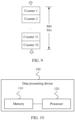
- FIG. 10 is a schematic diagram of a structure of a data processing device according to an embodiment of this application.
- the data processing device 100 includes a processor 120 and a memory 110.
- the memory 110 is configured to store data.
- the processor 120 is configured to perform read/write access on the data stored in the memory 110.
- the processor 120 is specifically configured to: obtain a first child node in a compressed state from the memory 110 in response to a read request for target data when the first child node is not detected in the processor 120, where the first child node is a child node that is in an integrity tree and that is related to the target data, the integrity tree includes a plurality of root nodes and a plurality of child nodes, the plurality of child nodes are stored in the compressed state in the memory 110, and the plurality of root nodes are stored in a decompressed state in the processor 120; and decompress the first child node in the compressed state, and cache the decompressed first child node into the processor 120, where the first child node is used for integrity verification on the target data.
- the processor 120 is specifically configured to: obtain a to-be-removed second child node in the processor 120 when it is detected that a quantity of child nodes in the processor 120 reaches a preset value; and compress the to-be-removed second child node when it is detected that the to-be-removed second child node is changed, and replace a second child node in the memory 110 with the compressed second child node.
- the processor 120 is specifically configured to: pre-compress the to-be-removed second child node, and when a size of the pre-compressed second child node is greater than a size of a minimum storage unit of the memory 110, add a first value to a value of an overflow counter of the second child node, set a value of each sub-counter of the second child node to a second value, and re-compress the reset second child node.
- the first value is a positive number greater than 0, and the second value is a positive number.
- the first value is 1, and/or the second value is 0.
- the processor 120 is specifically configured to: when the value of each sub-counter of the second child node is set to the second value, re-determine a message authentication code MAC of the second child node; and write the re-determined MAC into the memory 110.
- a branching factor of the integrity tree is a preset parameter
- the preset parameter is a positive integer greater than 8 in exponential multiples of 2.
- the preset parameter is 16 or 32.
- the processor 120 is specifically configured to: perform parallel decompression on the first child node by using at least two threads; and/or perform parallel compression on the to-be-removed second child node by using at least two threads.
- the data processing device in this embodiment of this application may be configured to perform the technical solutions of the foregoing methods. Implementation principles and technical effects thereof are similar, and details are not described herein again.
- All or some of the foregoing embodiments may be implemented by using software, hardware, firmware, or any combination thereof.
- software is used to implement the embodiments, all or a part of the embodiments may be implemented in a form of a computer program product.
- the computer program product includes one or more computer instructions.
- the computer may be a general-purpose computer, a dedicated computer, a computer network, or another programmable apparatus.
- the computer instructions may be stored in a computer-readable storage medium or may be transmitted from a computer-readable storage medium to another computer-readable storage medium.
- the computer instructions may be transmitted from a website, computer, server, or data center to another website, computer, server, or data center in a wired (for example, a coaxial cable, an optical fiber, or a digital subscriber line (DSL)) or wireless (for example, infrared, radio, or microwave) manner.
- the computer-readable storage medium may be any usable medium accessible by the computer, or a data storage device, for example, a server or a data center, integrating one or more usable media.
- the usable medium may be a magnetic medium (for example, a floppy disk, a hard disk, or a magnetic tape), an optical medium (for example, a DVD), a semiconductor medium (for example, a solid state disk Solid State Disk (SSD)), or the like.
- a magnetic medium for example, a floppy disk, a hard disk, or a magnetic tape
- an optical medium for example, a DVD
- a semiconductor medium for example, a solid state disk Solid State Disk (SSD)
Landscapes
- Engineering & Computer Science (AREA)
- Theoretical Computer Science (AREA)
- Computer Security & Cryptography (AREA)
- Physics & Mathematics (AREA)
- General Engineering & Computer Science (AREA)
- General Physics & Mathematics (AREA)
- Computer Hardware Design (AREA)
- Software Systems (AREA)
- Health & Medical Sciences (AREA)
- Bioethics (AREA)
- General Health & Medical Sciences (AREA)
- Storage Device Security (AREA)
Claims (8)
- Datenverarbeitungsverfahren, das durch einen Prozessor einer Datenverarbeitungsvorrichtung durchgeführt wird, wobei die Datenverarbeitungsvorrichtung den Prozessor und einen Speicher umfasst, wobei der Prozessor vertrauenswürdig ist und der Speicher nicht vertrauenswürdig ist und der Prozessor ein Register und einen Cache umfasst, wobei das Verfahren die folgenden Schritte umfasst:• Erlangen (S 101) eines ersten untergeordneten Knotens in einem komprimierten Zustand aus dem Speicher als Reaktion auf eine Leseanforderung für Zieldaten, wenn der erste untergeordnete Knoten nicht in dem Cache des Prozessors detektiert wird,• wobei der erste untergeordnete Knoten ein untergeordneter Knoten ist, der sich in einem Integritätsbaum befindet und der mit den Zieldaten in Beziehung steht, wobei der Integritätsbaum eine hierarchische Datenstruktur ist, die eine Vielzahl von Stammknoten und eine Vielzahl von untergeordneten Knoten umfasst, wobei die Vielzahl von untergeordneten Knoten im komprimierten Zustand in dem Speicher gespeichert ist und die Vielzahl von Stammknoten in einem nicht komprimierten Zustand in dem Register des Prozessors gespeichert ist, wobei jeder Knoten unter der Vielzahl von Stammknoten und der Vielzahl von untergeordneten Knoten einen Nachrichtenauthentifizierungscode, MAC, als Tag des Knotens, einen Überlaufzähler und mehrere Unterzähler enthält;• Dekomprimieren (S 102) des ersten untergeordneten Knotens im komprimierten Zustand und Zwischenspeichern des dekomprimierten ersten untergeordneten Knotens in dem Cache des Prozessors und• Durchführen einer Verifizierung der Integrität des dekomprimierten ersten untergeordneten Knotens durch Vergleichen des MAC des ersten untergeordneten Knotens mit einem MAC, der durch den Prozessor anhand der mehreren Unterzähler des ersten untergeordneten Knotens und eines Teils der Unterzähler eines dem untergeordneten Knoten entsprechenden übergeordneten Knotens berechnet wird, wodurch der erste untergeordnete Knoten auch für eine Integritätsverifizierung der Zieldaten verwendet wird, und hierarchisches Durchführen dieser Verifizierung an dem übergeordneten und den nachfolgenden übergeordneten Knoten, bis ein Stammknoten erreicht wird,wobei das Verfahren ferner die folgenden Schritte umfasst:• Erlangen (S 201) eines zu entfernenden zweiten untergeordneten Knotens, der in dem Cache des Prozessors zwischengespeichert ist, wenn detektiert wird, dass eine Menge an untergeordneten Knoten, die in dem Cache des Prozessors zwischengespeichert sind, einen zuvor festgelegten Wert erreicht; und• Bestimmen, ob der zu entfernende zweite untergeordnete Knoten von einem ursprünglichen, in dem Speicher gespeicherten zweiten untergeordneten Knoten in den zu entfernenden zweiten untergeordneten Knoten geändert wird;∘ wenn der zu entfernende zweite untergeordnete Knoten nicht geändert wird, Entfernen des zu entfernenden zweiten untergeordneten Knotens von dem Prozessor;∘ wenn der zu entfernende zweite untergeordnete Knoten von dem ursprünglichen zweiten untergeordneten Knoten in den zu entfernenden zweiten untergeordneten Knoten geändert wird:• Komprimieren (S 202) des zu entfernenden zweiten untergeordneten Knotens, Ersetzen (S 202) des ursprünglichen zweiten untergeordneten Knotens in dem Speicher mit dem komprimierten zweiten untergeordneten Knoten und Entfernen (S 203) des zu entfernenden zweiten untergeordneten Knotens von dem Prozessor,• wobei das Komprimieren des zu entfernenden zweiten untergeordneten Knotens Folgendes umfasst:Vorkomprimieren (Schritt A1) des zu entfernenden zweiten untergeordneten Knotens; undwenn die Größe des vorkomprimierten zweiten untergeordneten Knotens nicht größer als eine Größe einer Mindestspeichereinheit des Speichers ist, Verwenden des vorkomprimierten zu entfernenden zweiten untergeordneten Knotens als den komprimierten zweiten untergeordneten Knoten,wenn die Größe des vorkomprimierten zweiten untergeordneten Knotens größer als die Größe der Mindestspeichereinheit des Speichers ist, Hinzufügen (Schritt A2) eines ersten Wertes zu einem Wert des Überlaufzählers des zweiten untergeordneten Knotens, Festlegen (Schritt A2) eines Wertes jedes Unterzählers des zweiten untergeordneten Knotens auf einen zweiten Wert, erneutes Komprimieren (Schritt A2) des zurückgesetzten zweiten untergeordneten Knotens und Verwenden des erneut komprimierten zurückgesetzten zweiten untergeordneten Knotens als den komprimierten zweiten untergeordneten Knoten, wobei der erste Wert eine positive Zahl größer als 0 ist und der zweite Wert eine positive Zahl ist.
- Verfahren nach Anspruch 1, wobei das Verfahren ferner Folgendes umfasst:∘ wenn der Wert jedes Unterzählers des zweiten untergeordneten Knotens auf den zweiten Wert festgelegt ist, Neubestimmen des MAC des zweiten untergeordneten Knotens; und∘ Schreiben des neu bestimmten MAC in den Speicher.
- Verfahren nach einem der Ansprüche 1 bis 2, wobei ein Verzweigungsfaktor des Integritätsbaums ein zuvor festgelegter Parameter ist, wobei der zuvor festgelegte Parameter eine positive ganze Zahl größer als 8 in Exponentialvielfachen von 2 ist.
- Verfahren nach Anspruch 3, wobei der zuvor festgelegte Parameter 16 oder 32 ist.
- Verfahren nach einem der Ansprüche 1 bis 2, wobei:∘ das Dekomprimieren des ersten untergeordneten Knotens im komprimierten Zustand Folgendes umfasst: Durchführen einer parallelen Dekomprimierung an dem ersten untergeordneten Knoten unter Verwendung von mindestens zwei Threads; und/oder∘ das Komprimieren des zweiten untergeordneten Knotens Folgendes umfasst: Durchführen einer parallelen Komprimierung an dem zweiten untergeordneten Knoten unter Verwendung von mindestens zwei Threads.
- Verfahren nach Anspruch 1 oder 2, wobei der erste Wert 1 ist und der zweite Wert 0 ist.
- Datenverarbeitungsvorrichtung, umfassend einen Speicher und einen Prozessor, wobei der Prozessor vertrauenswürdig ist und der Speicher nicht vertrauenswürdig ist, wobei der Prozessor ein Register und einen Cache umfasst und die Datenverarbeitungsvorrichtung dazu konfiguriert ist, ein beliebiges der Verfahren nach Anspruch 1-6 durchzuführen.
- Computerspeichermedium, das ein computerlesbares Programm speichert, wobei, wenn das computerlesbare Programm durch die Datenverarbeitungsvorrichtung nach Anspruch 7 ausgeführt wird, die Datenverarbeitungsvorrichtung dazu veranlasst wird, ein beliebiges der Verfahren nach Anspruch 1-6 durchzuführen.
Applications Claiming Priority (1)
| Application Number | Priority Date | Filing Date | Title |
|---|---|---|---|
| PCT/CN2020/101415 WO2022006880A1 (zh) | 2020-07-10 | 2020-07-10 | 数据处理方法、设备与存储介质 |
Publications (3)
| Publication Number | Publication Date |
|---|---|
| EP4170536A1 EP4170536A1 (de) | 2023-04-26 |
| EP4170536A4 EP4170536A4 (de) | 2023-08-02 |
| EP4170536B1 true EP4170536B1 (de) | 2024-09-25 |
Family
ID=79552250
Family Applications (1)
| Application Number | Title | Priority Date | Filing Date |
|---|---|---|---|
| EP20943904.1A Active EP4170536B1 (de) | 2020-07-10 | 2020-07-10 | Datenverarbeitungsverfahren und -vorrichtung sowie speichermedium |
Country Status (4)
| Country | Link |
|---|---|
| US (1) | US12406097B2 (de) |
| EP (1) | EP4170536B1 (de) |
| CN (1) | CN114270353B (de) |
| WO (1) | WO2022006880A1 (de) |
Families Citing this family (3)
| Publication number | Priority date | Publication date | Assignee | Title |
|---|---|---|---|---|
| CN115065636B (zh) * | 2022-04-29 | 2024-09-20 | 北京达佳互联信息技术有限公司 | 数据分发方法、装置、电子设备及存储介质 |
| CN119210461B (zh) * | 2023-11-09 | 2025-06-24 | 华为云计算技术有限公司 | 一种数据压缩方法、数据解压方法及装置 |
| CN118212322A (zh) * | 2024-04-09 | 2024-06-18 | 北京火山引擎科技有限公司 | 一种适用于流程编辑的有向图布局方法及装置 |
Family Cites Families (12)
| Publication number | Priority date | Publication date | Assignee | Title |
|---|---|---|---|---|
| US6956507B2 (en) * | 2002-12-12 | 2005-10-18 | International Business Machines Corporation | Method and apparatus for morphing memory compressed machines |
| WO2012001208A1 (en) * | 2010-06-28 | 2012-01-05 | Nokia Corporation | Haptic surface compression |
| US9798900B2 (en) | 2015-03-26 | 2017-10-24 | Intel Corporation | Flexible counter system for memory protection |
| CN105069379B (zh) * | 2015-07-29 | 2017-11-21 | 哈尔滨工程大学 | 一种基于写计数器的存储器完整性保护方法 |
| US10243990B1 (en) * | 2016-09-23 | 2019-03-26 | Apple Inc. | Systems and methods for detecting replay attacks on security space |
| US10402574B2 (en) * | 2016-12-30 | 2019-09-03 | Intel Corporation | Techniques for multi-domain memory encryption |
| US10528486B2 (en) * | 2017-06-30 | 2020-01-07 | Intel Corporation | Techniques for crypto-aware cache partitioning |
| EP3662404B1 (de) * | 2017-08-03 | 2021-09-01 | ARM Limited | Zählerintegritätsbaum für speichersicherheit |
| US10846437B2 (en) * | 2018-06-28 | 2020-11-24 | Intel Corporation | Compressed integrity check counters in memory |
| CN109379397B (zh) * | 2018-08-31 | 2019-12-06 | 阿里巴巴集团控股有限公司 | 基于区块链的交易共识处理方法及装置、电子设备 |
| US20200175074A1 (en) * | 2018-12-04 | 2020-06-04 | Vmware, Inc. | Tree structure aware cache eviction policy |
| GB2579849B (en) * | 2018-12-18 | 2021-08-25 | Advanced Risc Mach Ltd | Integrity tree for memory integrity checking |
-
2020
- 2020-07-10 WO PCT/CN2020/101415 patent/WO2022006880A1/zh not_active Ceased
- 2020-07-10 EP EP20943904.1A patent/EP4170536B1/de active Active
- 2020-07-10 CN CN202080058013.8A patent/CN114270353B/zh active Active
-
2023
- 2023-01-09 US US18/151,890 patent/US12406097B2/en active Active
Also Published As
| Publication number | Publication date |
|---|---|
| CN114270353B (zh) | 2025-10-31 |
| US20230161916A1 (en) | 2023-05-25 |
| WO2022006880A1 (zh) | 2022-01-13 |
| US12406097B2 (en) | 2025-09-02 |
| CN114270353A (zh) | 2022-04-01 |
| EP4170536A4 (de) | 2023-08-02 |
| EP4170536A1 (de) | 2023-04-26 |
Similar Documents
| Publication | Publication Date | Title |
|---|---|---|
| US12406097B2 (en) | Data processing method and device and storage medium | |
| US11494499B1 (en) | Searching encrypted data stores | |
| US11977518B2 (en) | Method and system for data deduplication and compression in untrusted storage system | |
| CN106022155A (zh) | 用于数据库安全管理的方法及服务器 | |
| US12519653B2 (en) | Resource allocation method and apparatus, and storage medium | |
| US10846373B2 (en) | Method and system for securing a client's access to a DRM agent's services for a video player | |
| US20250245383A1 (en) | Method for data protection, electronic device and computer-readable storage medium | |
| WO2020044095A1 (zh) | 文件加密方法、装置、设备/终端/服务器及计算机可读存储介质 | |
| US12450365B2 (en) | Method and system for differential deduplication in untrusted storage | |
| WO2020000491A1 (zh) | 一种文件存储方法、装置及存储介质 | |
| GB2604903A (en) | Detection of Ransomware | |
| WO2016173267A1 (zh) | 一种完整性校验方法和装置 | |
| CN110516457B (zh) | 一种数据存储方法及读取方法、存储设备 | |
| CN112395613B (zh) | 静态特征库的加载方法、装置及设备 | |
| CN120012139B (zh) | 文件加密存储方法、存储介质及设备 | |
| CN113935056B (zh) | 数据处理方法、装置、设备、可读存储介质及程序产品 | |
| CN118573388A (zh) | 一种基于逻辑运算文件块的加解密方法及设备 | |
| CN116975904A (zh) | 一种数据处理方法、设备及系统 | |
| CN116490869A (zh) | 用于对不可信存储器中的已加密数据块进行密钥更新的方法和系统 | |
| CN119226282A (zh) | 一种加密数据的数据销毁方法 | |
| CN117375818A (zh) | 密钥存储和读取方法及装置 | |
| CN120811635A (zh) | 低成本嵌入产品输出文件的高效加密方法、系统及终端 |
Legal Events
| Date | Code | Title | Description |
|---|---|---|---|
| STAA | Information on the status of an ep patent application or granted ep patent |
Free format text: STATUS: THE INTERNATIONAL PUBLICATION HAS BEEN MADE |
|
| PUAI | Public reference made under article 153(3) epc to a published international application that has entered the european phase |
Free format text: ORIGINAL CODE: 0009012 |
|
| STAA | Information on the status of an ep patent application or granted ep patent |
Free format text: STATUS: REQUEST FOR EXAMINATION WAS MADE |
|
| 17P | Request for examination filed |
Effective date: 20230123 |
|
| AK | Designated contracting states |
Kind code of ref document: A1 Designated state(s): AL AT BE BG CH CY CZ DE DK EE ES FI FR GB GR HR HU IE IS IT LI LT LU LV MC MK MT NL NO PL PT RO RS SE SI SK SM TR |
|
| REG | Reference to a national code |
Ref country code: DE Ref legal event code: R079 Free format text: PREVIOUS MAIN CLASS: G06F0021780000 Ipc: G06F0021640000 Ref document number: 602020038533 Country of ref document: DE |
|
| A4 | Supplementary search report drawn up and despatched |
Effective date: 20230629 |
|
| RIC1 | Information provided on ipc code assigned before grant |
Ipc: G06F 21/78 20130101ALI20230623BHEP Ipc: G06F 21/64 20130101AFI20230623BHEP |
|
| DAV | Request for validation of the european patent (deleted) | ||
| DAX | Request for extension of the european patent (deleted) | ||
| GRAP | Despatch of communication of intention to grant a patent |
Free format text: ORIGINAL CODE: EPIDOSNIGR1 |
|
| STAA | Information on the status of an ep patent application or granted ep patent |
Free format text: STATUS: GRANT OF PATENT IS INTENDED |
|
| INTG | Intention to grant announced |
Effective date: 20240515 |
|
| GRAS | Grant fee paid |
Free format text: ORIGINAL CODE: EPIDOSNIGR3 |
|
| GRAA | (expected) grant |
Free format text: ORIGINAL CODE: 0009210 |
|
| STAA | Information on the status of an ep patent application or granted ep patent |
Free format text: STATUS: THE PATENT HAS BEEN GRANTED |
|
| AK | Designated contracting states |
Kind code of ref document: B1 Designated state(s): AL AT BE BG CH CY CZ DE DK EE ES FI FR GB GR HR HU IE IS IT LI LT LU LV MC MK MT NL NO PL PT RO RS SE SI SK SM TR |
|
| REG | Reference to a national code |
Ref country code: GB Ref legal event code: FG4D |
|
| REG | Reference to a national code |
Ref country code: CH Ref legal event code: EP |
|
| REG | Reference to a national code |
Ref country code: DE Ref legal event code: R096 Ref document number: 602020038533 Country of ref document: DE |
|
| REG | Reference to a national code |
Ref country code: IE Ref legal event code: FG4D |
|
| REG | Reference to a national code |
Ref country code: LT Ref legal event code: MG9D |
|
| PG25 | Lapsed in a contracting state [announced via postgrant information from national office to epo] |
Ref country code: NO Free format text: LAPSE BECAUSE OF FAILURE TO SUBMIT A TRANSLATION OF THE DESCRIPTION OR TO PAY THE FEE WITHIN THE PRESCRIBED TIME-LIMIT Effective date: 20241225 |
|
| PG25 | Lapsed in a contracting state [announced via postgrant information from national office to epo] |
Ref country code: GR Free format text: LAPSE BECAUSE OF FAILURE TO SUBMIT A TRANSLATION OF THE DESCRIPTION OR TO PAY THE FEE WITHIN THE PRESCRIBED TIME-LIMIT Effective date: 20241226 Ref country code: FI Free format text: LAPSE BECAUSE OF FAILURE TO SUBMIT A TRANSLATION OF THE DESCRIPTION OR TO PAY THE FEE WITHIN THE PRESCRIBED TIME-LIMIT Effective date: 20240925 |
|
| PG25 | Lapsed in a contracting state [announced via postgrant information from national office to epo] |
Ref country code: BG Free format text: LAPSE BECAUSE OF FAILURE TO SUBMIT A TRANSLATION OF THE DESCRIPTION OR TO PAY THE FEE WITHIN THE PRESCRIBED TIME-LIMIT Effective date: 20240925 |
|
| PG25 | Lapsed in a contracting state [announced via postgrant information from national office to epo] |
Ref country code: LV Free format text: LAPSE BECAUSE OF FAILURE TO SUBMIT A TRANSLATION OF THE DESCRIPTION OR TO PAY THE FEE WITHIN THE PRESCRIBED TIME-LIMIT Effective date: 20240925 |
|
| PG25 | Lapsed in a contracting state [announced via postgrant information from national office to epo] |
Ref country code: RS Free format text: LAPSE BECAUSE OF FAILURE TO SUBMIT A TRANSLATION OF THE DESCRIPTION OR TO PAY THE FEE WITHIN THE PRESCRIBED TIME-LIMIT Effective date: 20241225 |
|
| REG | Reference to a national code |
Ref country code: NL Ref legal event code: MP Effective date: 20240925 |
|
| PG25 | Lapsed in a contracting state [announced via postgrant information from national office to epo] |
Ref country code: RS Free format text: LAPSE BECAUSE OF FAILURE TO SUBMIT A TRANSLATION OF THE DESCRIPTION OR TO PAY THE FEE WITHIN THE PRESCRIBED TIME-LIMIT Effective date: 20241225 Ref country code: NO Free format text: LAPSE BECAUSE OF FAILURE TO SUBMIT A TRANSLATION OF THE DESCRIPTION OR TO PAY THE FEE WITHIN THE PRESCRIBED TIME-LIMIT Effective date: 20241225 Ref country code: LV Free format text: LAPSE BECAUSE OF FAILURE TO SUBMIT A TRANSLATION OF THE DESCRIPTION OR TO PAY THE FEE WITHIN THE PRESCRIBED TIME-LIMIT Effective date: 20240925 Ref country code: GR Free format text: LAPSE BECAUSE OF FAILURE TO SUBMIT A TRANSLATION OF THE DESCRIPTION OR TO PAY THE FEE WITHIN THE PRESCRIBED TIME-LIMIT Effective date: 20241226 Ref country code: FI Free format text: LAPSE BECAUSE OF FAILURE TO SUBMIT A TRANSLATION OF THE DESCRIPTION OR TO PAY THE FEE WITHIN THE PRESCRIBED TIME-LIMIT Effective date: 20240925 Ref country code: BG Free format text: LAPSE BECAUSE OF FAILURE TO SUBMIT A TRANSLATION OF THE DESCRIPTION OR TO PAY THE FEE WITHIN THE PRESCRIBED TIME-LIMIT Effective date: 20240925 |
|
| REG | Reference to a national code |
Ref country code: AT Ref legal event code: MK05 Ref document number: 1727265 Country of ref document: AT Kind code of ref document: T Effective date: 20240925 |
|
| PG25 | Lapsed in a contracting state [announced via postgrant information from national office to epo] |
Ref country code: NL Free format text: LAPSE BECAUSE OF FAILURE TO SUBMIT A TRANSLATION OF THE DESCRIPTION OR TO PAY THE FEE WITHIN THE PRESCRIBED TIME-LIMIT Effective date: 20240925 |
|
| PG25 | Lapsed in a contracting state [announced via postgrant information from national office to epo] |
Ref country code: IS Free format text: LAPSE BECAUSE OF FAILURE TO SUBMIT A TRANSLATION OF THE DESCRIPTION OR TO PAY THE FEE WITHIN THE PRESCRIBED TIME-LIMIT Effective date: 20250125 Ref country code: PT Free format text: LAPSE BECAUSE OF FAILURE TO SUBMIT A TRANSLATION OF THE DESCRIPTION OR TO PAY THE FEE WITHIN THE PRESCRIBED TIME-LIMIT Effective date: 20250127 |
|
| PG25 | Lapsed in a contracting state [announced via postgrant information from national office to epo] |
Ref country code: RO Free format text: LAPSE BECAUSE OF FAILURE TO SUBMIT A TRANSLATION OF THE DESCRIPTION OR TO PAY THE FEE WITHIN THE PRESCRIBED TIME-LIMIT Effective date: 20240925 Ref country code: SM Free format text: LAPSE BECAUSE OF FAILURE TO SUBMIT A TRANSLATION OF THE DESCRIPTION OR TO PAY THE FEE WITHIN THE PRESCRIBED TIME-LIMIT Effective date: 20240925 |
|
| PG25 | Lapsed in a contracting state [announced via postgrant information from national office to epo] |
Ref country code: ES Free format text: LAPSE BECAUSE OF FAILURE TO SUBMIT A TRANSLATION OF THE DESCRIPTION OR TO PAY THE FEE WITHIN THE PRESCRIBED TIME-LIMIT Effective date: 20240925 |
|
| PG25 | Lapsed in a contracting state [announced via postgrant information from national office to epo] |
Ref country code: EE Free format text: LAPSE BECAUSE OF FAILURE TO SUBMIT A TRANSLATION OF THE DESCRIPTION OR TO PAY THE FEE WITHIN THE PRESCRIBED TIME-LIMIT Effective date: 20240925 Ref country code: AT Free format text: LAPSE BECAUSE OF FAILURE TO SUBMIT A TRANSLATION OF THE DESCRIPTION OR TO PAY THE FEE WITHIN THE PRESCRIBED TIME-LIMIT Effective date: 20240925 |
|
| PG25 | Lapsed in a contracting state [announced via postgrant information from national office to epo] |
Ref country code: CZ Free format text: LAPSE BECAUSE OF FAILURE TO SUBMIT A TRANSLATION OF THE DESCRIPTION OR TO PAY THE FEE WITHIN THE PRESCRIBED TIME-LIMIT Effective date: 20240925 Ref country code: PL Free format text: LAPSE BECAUSE OF FAILURE TO SUBMIT A TRANSLATION OF THE DESCRIPTION OR TO PAY THE FEE WITHIN THE PRESCRIBED TIME-LIMIT Effective date: 20240925 |
|
| PG25 | Lapsed in a contracting state [announced via postgrant information from national office to epo] |
Ref country code: SK Free format text: LAPSE BECAUSE OF FAILURE TO SUBMIT A TRANSLATION OF THE DESCRIPTION OR TO PAY THE FEE WITHIN THE PRESCRIBED TIME-LIMIT Effective date: 20240925 Ref country code: IT Free format text: LAPSE BECAUSE OF FAILURE TO SUBMIT A TRANSLATION OF THE DESCRIPTION OR TO PAY THE FEE WITHIN THE PRESCRIBED TIME-LIMIT Effective date: 20240925 |
|
| REG | Reference to a national code |
Ref country code: DE Ref legal event code: R097 Ref document number: 602020038533 Country of ref document: DE |
|
| PG25 | Lapsed in a contracting state [announced via postgrant information from national office to epo] |
Ref country code: DK Free format text: LAPSE BECAUSE OF FAILURE TO SUBMIT A TRANSLATION OF THE DESCRIPTION OR TO PAY THE FEE WITHIN THE PRESCRIBED TIME-LIMIT Effective date: 20240925 |
|
| PLBE | No opposition filed within time limit |
Free format text: ORIGINAL CODE: 0009261 |
|
| STAA | Information on the status of an ep patent application or granted ep patent |
Free format text: STATUS: NO OPPOSITION FILED WITHIN TIME LIMIT |
|
| 26N | No opposition filed |
Effective date: 20250626 |
|
| PG25 | Lapsed in a contracting state [announced via postgrant information from national office to epo] |
Ref country code: SE Free format text: LAPSE BECAUSE OF FAILURE TO SUBMIT A TRANSLATION OF THE DESCRIPTION OR TO PAY THE FEE WITHIN THE PRESCRIBED TIME-LIMIT Effective date: 20240925 |
|
| PGFP | Annual fee paid to national office [announced via postgrant information from national office to epo] |
Ref country code: DE Payment date: 20250604 Year of fee payment: 6 |
|
| PG25 | Lapsed in a contracting state [announced via postgrant information from national office to epo] |
Ref country code: HR Free format text: LAPSE BECAUSE OF FAILURE TO SUBMIT A TRANSLATION OF THE DESCRIPTION OR TO PAY THE FEE WITHIN THE PRESCRIBED TIME-LIMIT Effective date: 20240925 |
|
| REG | Reference to a national code |
Ref country code: CH Ref legal event code: H13 Free format text: ST27 STATUS EVENT CODE: U-0-0-H10-H13 (AS PROVIDED BY THE NATIONAL OFFICE) Effective date: 20260224 |
|
| PG25 | Lapsed in a contracting state [announced via postgrant information from national office to epo] |
Ref country code: LU Free format text: LAPSE BECAUSE OF NON-PAYMENT OF DUE FEES Effective date: 20250710 |
|
| GBPC | Gb: european patent ceased through non-payment of renewal fee |
Effective date: 20250710 |
|
| REG | Reference to a national code |
Ref country code: BE Ref legal event code: MM Effective date: 20250731 |
|
| PG25 | Lapsed in a contracting state [announced via postgrant information from national office to epo] |
Ref country code: GB Free format text: LAPSE BECAUSE OF NON-PAYMENT OF DUE FEES Effective date: 20250710 |
|
| PG25 | Lapsed in a contracting state [announced via postgrant information from national office to epo] |
Ref country code: BE Free format text: LAPSE BECAUSE OF NON-PAYMENT OF DUE FEES Effective date: 20250731 |
|
| PG25 | Lapsed in a contracting state [announced via postgrant information from national office to epo] |
Ref country code: FR Free format text: LAPSE BECAUSE OF NON-PAYMENT OF DUE FEES Effective date: 20250731 |