EP4170629A1 - System zur berechnung der mission eines luftfahrzeugs, das zur berechnung eines umgebungsbenutzungsindex geeignet ist, und verfahren dafür - Google Patents
System zur berechnung der mission eines luftfahrzeugs, das zur berechnung eines umgebungsbenutzungsindex geeignet ist, und verfahren dafür Download PDFInfo
- Publication number
- EP4170629A1 EP4170629A1 EP22202202.2A EP22202202A EP4170629A1 EP 4170629 A1 EP4170629 A1 EP 4170629A1 EP 22202202 A EP22202202 A EP 22202202A EP 4170629 A1 EP4170629 A1 EP 4170629A1
- Authority
- EP
- European Patent Office
- Prior art keywords
- trajectory
- mission
- environmental benefit
- calculation
- potential
- Prior art date
- Legal status (The legal status is an assumption and is not a legal conclusion. Google has not performed a legal analysis and makes no representation as to the accuracy of the status listed.)
- Granted
Links
Images


Classifications
-
- G—PHYSICS
- G01—MEASURING; TESTING
- G01C—MEASURING DISTANCES, LEVELS OR BEARINGS; SURVEYING; NAVIGATION; GYROSCOPIC INSTRUMENTS; PHOTOGRAMMETRY OR VIDEOGRAMMETRY
- G01C21/00—Navigation; Navigational instruments not provided for in groups G01C1/00 - G01C19/00
- G01C21/20—Instruments for performing navigational calculations
-
- G—PHYSICS
- G05—CONTROLLING; REGULATING
- G05D—SYSTEMS FOR CONTROLLING OR REGULATING NON-ELECTRIC VARIABLES
- G05D1/00—Control of position, course, altitude or attitude of land, water, air or space vehicles, e.g. using automatic pilots
- G05D1/0005—Control of position, course, altitude or attitude of land, water, air or space vehicles, e.g. using automatic pilots with arrangements to save energy
-
- G—PHYSICS
- G08—SIGNALLING
- G08G—TRAFFIC CONTROL SYSTEMS
- G08G5/00—Traffic control systems for aircraft
- G08G5/20—Arrangements for acquiring, generating, sharing or displaying traffic information
- G08G5/21—Arrangements for acquiring, generating, sharing or displaying traffic information located onboard the aircraft
-
- G—PHYSICS
- G08—SIGNALLING
- G08G—TRAFFIC CONTROL SYSTEMS
- G08G5/00—Traffic control systems for aircraft
- G08G5/30—Flight plan management
- G08G5/32—Flight plan management for flight plan preparation
-
- G—PHYSICS
- G08—SIGNALLING
- G08G—TRAFFIC CONTROL SYSTEMS
- G08G5/00—Traffic control systems for aircraft
- G08G5/50—Navigation or guidance aids
- G08G5/55—Navigation or guidance aids for a single aircraft
-
- G—PHYSICS
- G08—SIGNALLING
- G08G—TRAFFIC CONTROL SYSTEMS
- G08G5/00—Traffic control systems for aircraft
- G08G5/50—Navigation or guidance aids
- G08G5/59—Navigation or guidance aids in accordance with predefined flight zones, e.g. to avoid prohibited zones
-
- G—PHYSICS
- G08—SIGNALLING
- G08G—TRAFFIC CONTROL SYSTEMS
- G08G5/00—Traffic control systems for aircraft
- G08G5/70—Arrangements for monitoring traffic-related situations or conditions
- G08G5/76—Arrangements for monitoring traffic-related situations or conditions for monitoring atmospheric conditions
Definitions
- the invention applies to aircraft used in civil aviation, in particular in business aviation.
- Such a calculation system is in particular intended to be integrated into a cockpit, in parallel with a flight control system (“Flight Management System” or “FMS” in English), to allow the crew to determine trajectories of assignment.
- FMS Flight Management System
- the calculation system is suitable for being integrated into an off-board mission planning system, for example into an airport infrastructure for establishing aircraft trajectory, into an electronic flight bag (“Electronic Flight Bag” or “EFB”,), and/or in a portable electronic device (for example a tablet), or in a computer of the PC or server type on the ground.
- an off-board mission planning system for example into an airport infrastructure for establishing aircraft trajectory, into an electronic flight bag (“Electronic Flight Bag” or “EFB”,), and/or in a portable electronic device (for example a tablet), or in a computer of the PC or server type on the ground.
- EFB Electronic Flight Bag
- the calculation system is adapted to determine a complete trajectory of the aircraft between a first geographical point of origin and a second geographical point of destination.
- the mission includes one or more steps.
- the preparation and definition of an aircraft mission between a first geographical point and a second geographical point is a time-consuming task. It requires in particular to determine the route that the aircraft will follow, the associated flight profile, the loading of passengers, freight and fuel and the calculation of low-speed performance, as well as the verification of the flight envelope of the aircraft. .
- This definition is made according to a mission context including the meteorology, the air routes to be taken, the connectivity with satellite communication systems and an aircraft context which includes the configuration and the type of aircraft used, as well as than its working condition.
- the airlines and/or external suppliers have calculation systems making it possible to provide a flight plan and the expected aircraft performance, for example a quantity of fuel required.
- mission conditions including take-off times, are subject to change and the destination may change quickly depending on the passengers' own needs.
- these systems are designed to operate on a sum of input criteria (speed, flight level, number of passengers, etc.) to which a single navigation solution will correspond. It is therefore frequently necessary to perform several iterations to adjust the mission hypotheses.
- trajectory solutions proposed by the supplier are not satisfactory for the customer and/or result in a non-optimal flight time and/or in increased fuel consumption.
- EP 3 489 931 describes a mission calculation system of the aforementioned type, in which a user can choose operational specifications of the mission, and determine at least one optimal trajectory of the mission, which takes account of the operational specifications defined by the user, by offering different options to the user.
- Aircraft manufacturers aim to reduce the emissions produced by aircraft, by improving the design of aircraft, for example by modifying their aerodynamics and/or by making them lighter.
- the impact on the environment of an optimized trajectory compared to a basic trajectory provided by an external supplier, or in absolute terms, is not easily controlled or quantified by a user of the aircraft.
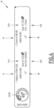
- a first mission calculation system 10 according to the invention which, in this example, is present in the cockpit 12 of an aircraft, is illustrated by the figure 1 .
- the aircraft is preferably a civil aircraft, in particular a business aircraft.
- the cockpit 12 of the aircraft is intended to control all the systems of the aircraft during its use.
- the cockpit 12 comprises in particular, in addition to the mission calculation system 10, a flight control system 14 of the cockpit of the aircraft (“Flight Management System” in English or “FMS”), and a system 16 for management and monitoring of the various aircraft systems.
- the flight control system 14 is intended to assist the pilot of the aircraft to control the navigation of the aircraft during a mission. It is suitable for providing information in particular on the route followed by the aircraft, and on parameters of evolution of the aircraft such as fuel consumption.
- the system 16 for managing and monitoring the various aircraft systems is in particular intended to enable the crew to monitor and possibly to pilot all of the aircraft systems. It is suitable in particular for determining an operating state of the aircraft, in particular the presence of faults and breakdowns present on the aircraft on the ground and/or in flight.
- the mission calculation system 10 is connected to the management system 16 to take into account the state of the airplane in the mission calculations.
- the mission carried out by the aircraft comprises at least one step 22 (or "leg"), represented schematically on the figure 5 , between a first geographic point 18 of origin and a second geographic point 20 of destination.
- the mission carried out by the aircraft comprises a plurality of successive stages 22, the second geographical point 20 of destination of a first stage constituting the first geographical point 18 of origin of a second stage .
- the mission is carried out by following operational specifications which include in particular a mission context, an aircraft context, a passenger context and possibly a path optimization mode.
- the mission context comprises, for example, at least one operating constraint, in particular a number of passengers to be transported, a maximum take-off weight linked in particular to an available runway length, a navigation fuel load, a reserve fuel load , an imposed departure time and/or arrival time, a maximum distance to be covered, and/or a distance to an alternative ground en route.
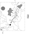
- the mission context advantageously includes navigation constraints, such as for example prohibited zones 24 or flight levels, air routes 26 or imposed flight levels, or more generally free flight zones and/or flight imposed by the airways.
- the mission context advantageously includes meteorological constraints such as zones 28 of dangerous meteorological phenomena, in particular formation of frost or cumulonimbus clouds.
- the mission context possibly also includes passenger comfort constraints, in particular areas of turbulence to be avoided, in particular according to a desired level of turbulence, chosen for example from a low level, a medium level, and a high level.
- the different zones 24, 28, 30, 32 are preferably defined by horizontal coordinates (for example latitude and longitude) and by vertical coordinates in altitude.
- the position of these zones changes advantageously over time.
- the aforementioned coordinates change over time, defining a four-dimensional (or 4D) zone of avoidance or, on the contrary, a four-dimensional zone of desired or constrained passage.
- Zones 24, 28, 30, 32 therefore define horizontal sections of avoidance or, on the contrary, horizontal sections of desired or constrained passage. They also define, in the vertical plane, vertical sections of avoidance or, on the contrary, vertical sections of desired or constrained passage. The position of zones 24, 28, 30, 32 advantageously evolves over time.
- the aircraft context may include usage constraints linked to departure authorizations (or "dispatch") and/or constraints linked to a particular state of the aircraft in terms of faults and/or breakdowns on one or more equipment of the aircraft.
- a departure authorization linked to certain faults in the aircraft can impose a maximum flight level and/or a maximum speed. Failure to retract the landing gear or a flap can also impose an increased fuel consumption constraint.
- the trajectory optimization mode includes for example a minimization of the amount of fuel carried by the aircraft, a reduced Mach of the aircraft, an exact calculation of the weight and the balance of the aircraft, a vertical optimization of trajectory authorizing flight at several flight levels, and/or route optimization involving a trajectory in free flight or constrained by air routes, this being able to be optimized piecemeal and therefore having different optimization criteria on the same flight depending on the areas crossed.
- Obtaining the trajectory in free flight is optionally followed by an optimization of the trajectory around the trajectory in free flight to respect the imposed waypoints, and the imposed trajectories between the imposed waypoints.
- the mission calculation system 10 is intended to establish at least one potential trajectory of the aircraft to perform step 22 between at least one first geographical point 18 of origin and at least one second geographical point 20 of destination, taking account of the operational specifications, in particular the mission context, the aircraft context and the optimization mode.
- the mission calculation system 10 is intended to establish, prior to the mission, a plurality of potential trajectories of the aircraft according to different operational specifications, to allow the user to have several trajectory opportunities.
- the mission calculation system 10 is intended to establish, upon selection by the user, at least one potential trajectory from a base trajectory by modifying the operational specifications on at least one optimization zone and/or one avoidance zone.
- the mission calculation system 10 is able to determine, for the or for each potential trajectory, an environmental benefit index associated with the potential trajectory.
- the trajectory obtained via the mission calculation system 10 includes the route of the aircraft in latitude and longitude, possibly with a vertical flight profile, defined by one or more altitudes and transit times.
- the mission calculation system 10 is also capable of establishing flight plan parameters, in particular the weight and balance of the aircraft, the take-off and landing card (that is to say the flight data for the pilot relating to the guidance such as the speeds V1, V2, VR on the runway, the acceleration on releasing the brakes, the engine speed at takeoff, and/or the attitude at takeoff), the calculation of the take-off and landing weight limits, low-speed (i.e. surface) and high-speed (i.e.
- the mission calculation system 10 comprises a trajectory calculation engine 40 and advantageously, a user interface 42 for parameterization and restitution forming a mission plate. It includes a module 43 for calculating the environmental benefit index associated with each trajectory established by the calculation engine 40.
- the user interface 42 comprises for example at least one display 44, associated with a display manager 44A on the display 44 and at least one member 46 for selecting and entering information by the user, which can be a real or virtual keyboard, a mouse and/or a touch system.
- the user interface 42 is capable of authorizing the user to enter at least part of the operational specifications, in particular the geographical points 18, 20 of origin and destination, waypoints, desired times, desired loads, maximum wind on the trajectory, etc.
- the user interface 42 is also suitable for displaying at least one window 45 for presenting environmental benefit indicators according to the trajectories established according to predefined operational specifications (see figure 4 ), and if applicable, a window 47 for selection, by the user, of a trajectory optimization mode, when the user wishes to determine the environmental benefit of a particular trajectory option.
- interface 42 An example of interface 42 is described in the French patent application entitled “Mission calculation system for an aircraft, comprising a mission plate and associated method” filed under number 17 01234 by the Applicant.
- the calculation engine 40 is connected to the interface 42. It is advantageously also connected to the flight control system 14, to the management and monitoring system 16.
- the weather database 50 contains current and predictive weather data in the navigation area of the aircraft in a mission volume extending between the origin point 18 and the destination point 20.
- the mission volume has preferably a significant width, for example at least 700 nautical miles, on either side of the orthodromic trajectory between the point of origin 18 and the point of destination 20.
- meteorological data are provided at several flight levels, for example every 304 m (1000 feet), at an altitude comprised for example between 0 m and 15545 m (51000 feet).
- Meteorological data is provided in altitude but also by providing a weather component that evolves over time.
- This evolving component is obtained using meteorological forecast data, which may include a plurality of meteorological maps at successive instants in time (for example every hour).
- meteorological data include wind speed and direction, temperature, pressure, precipitation, hazardous phenomena (frost, thunderstorms / cumulonimbus), turbulence, level of the tropopause, ash clouds volcano, dust / sand clouds, visibility, as well as aeronautical observations in the area or en route (METAR, PIREPS) and area forecasts (TAF)... They may include the definition and evolution over time and in space the geographical coordinates of zones 28 of dangerous meteorological phenomena and/or zones of turbulence 30.
- meteorological data define a meteorological context, preferably changing, in the mission volume extending between the geographical point of origin 18 and the geographical point of destination 20.
- the navigation information database 52 contains terrain information data at the origin point 18 and the destination point 20, and between these points 18, 20.
- the navigation information database 52 advantageously comprises an airport sub-database (runway lengths, runway orientation, slopes, etc.) and a navigation sub-database.
- the navigation data includes in particular a network of waypoints 53A (or “waypoints”) and the trajectories 53B imposed between the waypoints, as defined by the air authorities in each country (see figure 9 ).
- SATCOM satellite telecommunications coverage
- Calculation engine 40 comprises at least one computer comprising at least one processor 54 and one memory 56.
- Memory 56 contains software modules specific to being executed by processor 54.
- the modules are produced at least partially in the form of programmable logic components, or in the form of dedicated integrated circuits.
- the memory 56 contains a software module 58 for initializing mission specifications, suitable for acquiring operational specifications of the mission from in particular the interface 42, and comprising a software module 60 for recovering a context meteorological from the database 50, and a software module 62 for determining aircraft performance, depending on the mission specifications, the meteorological context and the aircraft context.
- a software module 58 for initializing mission specifications suitable for acquiring operational specifications of the mission from in particular the interface 42
- a software module 60 for recovering a context meteorological from the database 50
- a software module 62 for determining aircraft performance, depending on the mission specifications, the meteorological context and the aircraft context.
- the memory 56 also contains at least one software module 64, 65 for trajectory calculation according to the aircraft performance determined, the meteorological context and the mission specifications.
- the memory 56 contains a first software module 64 for calculating a first optimal mission trajectory 64A, as a function of the aircraft performance determined, the meteorological context and the mission specifications, the first calculation module 64 being able to calculate the first optimal mission trajectory 64A in an unconstrained manner by a network of waypoints 53A and/or trajectories 53B imposed between the waypoints 53A.
- the memory 56 also contains a module 63 for defining, around the first optimal mission trajectory 64A, a region to be optimized 63A of the optimal trajectory 64A and a second module 65 for calculating an optimized trajectory 65A of the aircraft in the region to be optimized 63A, in a constrained manner by a network of waypoints 53A and/or trajectories 53B imposed between the waypoints 53A.
- the initialization module 58 is able to acquire the operational specifications of the mission from the interface 42, and/or from the management and monitoring system 16.
- the determination module 62 includes a software application 66 for determining the weight and balance of the aircraft, intended to determine the center of gravity of the aircraft, a software application 68 for determining high speed performance, and advantageously a software application 70 for determining low speed performance.
- the application 66 for determining the weight and balance of the aircraft is suitable for determining the position of the center of gravity of the aircraft in the absence of fuel in the aircraft (or "Zero Fuel Weight Center of Gravity ”) and the weight of the aircraft in the absence of fuel in the aircraft (or “Zero Fuel Weight”), depending on the empty weight of the aircraft, the equipment on board the aircraft, the passengers and/or on-board freight, and their position in the aircraft, as well as monitoring of the aircraft's flight envelope (mass-centering diagram).
- the high-speed performance determination application 68 is capable of determining the mass of fuel to be loaded into the aircraft on a given trajectory, for example an orthodromic trajectory between the point of origin 18 and the point of destination 20, by using the position of the center of gravity and the weight of the aircraft in the absence of fuel in the aircraft (or “Zero Fuel Weight”) determined by the application 66, a predetermined air speed, for example entered or calculated from the data entered by the user interface 42, the meteorological context retrieved from the module 60, in particular wind speeds and temperatures and possibly the aircraft context , for example the type and age of the engines, retrieved from the initialization module 58.
- the high-speed performance determination application 68 further comprises functions for calculating instantaneous fuel consumption and instantaneous aircraft weight variation during a trajectory, advantageously using the position of the center of gravity and the weight of the aircraft.
- a predetermined air speed for example entered or calculated from the data entered by the user interface 42, the meteorological context retrieved from the module 60, in particular wind speeds and temperatures and possibly the aircraft context, for example the type and age of the engines, retrieved from the initialization module 58.
- the high-speed performance determination application 68 also includes a function for determining the flight levels that can be reached as a function of the predetermined airspeed, the meteorological context, and possibly the aircraft context.
- the low-speed performance determination application 70 is suitable for determining in particular the maximum weight of the aircraft (and the take-off card) allowing the aircraft to take off and/or land on a terrain, according to data track lengths retrieved from the database 52, and the meteorological context retrieved from the module 60.
- the first calculation module 64 is as described in the patent application EP3715786 of the Applicant.
- It is configured to calculate, from at least one chosen point accessible to the aircraft, a plurality of iso-displacement curves 78, in particular isochronous curves, fuel iso-consumption curves or curves of iso-cost, and possibly extended iso-displacement curves, to one or more flight levels.
- the first calculation module 64 is configured to choose an optimal trajectory 64A based on the iso-displacement curves 78 calculated.
- the first calculation module 64 is able to determine each point of the optimal trajectory 64A in an unconstrained manner by a network of passage points 53A and/or of trajectories 53B imposed between the passage points 53A.
- the determination of the optimal trajectory 64A by the first calculation module 64 is implemented as if the aircraft were able to perform a free flight taking into account the mission specifications, but without taking into account the network of waypoints 53A and/or 53B trajectories imposed between the 53A waypoints which are defined by the air traffic control authorities.
- the first calculation module 64 is able to thus define an optimal trajectory 64A not only in the horizontal plane, but advantageously also in the vertical plane.
- an isochronous curve is a curve connecting the points accessible to the aircraft from a given point (which may be the point of origin 18 or a point on an isochronous curve) in a given time which corresponds to a or more time increments.
- Each time increment is for example between 1 minute and 1 hour, in particular between 2 minutes and 10 minutes, for example 5 minutes.
- a fuel iso-consumption curve is a curve connecting the points accessible to the aircraft from a given point with a given fuel consumption which corresponds to one or more increments of fuel consumed.
- Each time increment consumed is chosen at a constant value, for example between 22.7 kg (50 lbs) and 453.6 kg (1000 lbs), in particular between 36.3 kg (80 lbs) and 54.4 kg (120 lbs). books).
- Each move increment is a cost increment of a given constant value.
- each iso-displacement curve is determined from a given point by calculating from the given point all the points accessible to the aircraft, at a given airspeed, taking into account the meteorological context, in particular the direction and the intensity of the wind, as provided by the recovery module 60 and the aircraft performance, as determined by the calculation functions of the application 68.
- the definition module 63 when present, is advantageously capable of defining the region to be optimized 63A of the trajectory as a function of a predetermined lateral distance at each point of the optimal trajectory 64A defined by the first calculation module 64 and according to the operational mission specifications, in particular the mission context, in particular the navigation constraints, the meteorological constraints, and the passenger comfort constraints.
- the definition module 63 is capable of laterally delimiting the region to be optimized 63A of the trajectory 64A by lateral limits extending laterally at a distance chosen according to the density of the aerial network of each point of the optimal trajectory 64A.
- the region 63A to be optimized is generally defined by a band encompassing the trajectory 64A.
- the band is also potentially constrained by prohibited flight zones 24, by zones 28 of dangerous meteorological phenomena and/or by turbulence zones 30. It encompasses, as the case may be, satellite coverage zones 32.
- the second module 65 for calculating trajectories 65A when present, includes an application for defining a network of nodes between the geographical point of origin 18 and the geographical point of destination 20 from the network of waypoints 53A and/or trajectories 53B imposed between the crossing points 53A, and an application for defining a cost associated with the passage from one node to an adjacent node among the nodes of the network.
- the second calculation module 65 also comprises an application for determining the optimized trajectory 65A in the network of nodes on the basis of a minimization of the total cumulative cost between the geographical point of origin 18 and the geographical point of destination 20.
- the algorithm is for example a Dijkstra algorithm and/or an A* algorithm.
- Dijkstra's algorithm takes as input the weighted network defined above between the geographical point of origin 18 and the geographical point of destination 20.
- a description of the A* algorithm is for example given in the article downloadable at the following address: https://fr.wikipedia.org/wiki/Algorithme_A*.
- the calculation engine 40 is advantageously able to determine at least one mission parameter of the aircraft corresponding to the optimal trajectory 64A or the optimized trajectory 65A, if applicable.
- the mission parameter is for example a total takeoff weight of the aircraft.
- This take-off weight is calculated at each iteration by the calculation module 64 then by the calculation module 65, on the basis of the estimated consumption on the trajectory between the point of origin 18 and the point of destination 20, calculated at the using functions for calculating instantaneous fuel consumption and variation in instantaneous aircraft weight, and on the basis of a passenger and freight load predefined in the operational specifications.
- the calculation engine 40 provides a trajectory data file defining the geographical coordinates of the trajectory as a function of time.
- This data file is suitable for being retrieved by the crew and/or for being loaded by manual entry or by transfer of data into the flight control system 14, with a view to being used during the flight.
- the environmental benefit index calculation module 43 is able to calculate, for the or each potential trajectory T obtained by the calculation module 40, an environmental benefit index GI(T), specific to this path.
- It comprises at least one computer comprising at least one processor and one memory, which are optionally common with the processor 54 and the memory 56 of the calculation engine 40.
- the memory contains software modules specific to being executed by the processor. As a variant, the modules are made at least partially in the form of programmable logic components, or else in the form of dedicated integrated circuits.
- the calculation module 43 is advantageously suitable for calculating the environmental benefit index of each potential trajectory established by the calculation engine 40, from at least two predefined reference trajectories TR1, TR2, and a correlation function established from the reference trajectories.
- the calculation module 43 is capable of activating the mission calculation engine 40 to define a first reference trajectory TR1 corresponding to a predefined mission minimizing the flight time between the point of origin 18 and the point of destination 20, and a second reference trajectory TR2 corresponding to a mission having a minimum environmental impact, in particular a minimum production of carbon dioxide.
- the calculation module 43 is able to initialize the calculation engine 40, to determine the mission which presents the shortest flight time between the point of origin 18 and the point of destination 20, by using the maximum acceptable speed high for the aircraft, using the airplane context and the meteorological context of the mission and the fastest trajectory in projection in the horizontal plane and in the vertical plane.
- the maximum acceptable speed is for example defined by a maximum acceptable (flyable) Mach, for a given aircraft model, for example greater than 0.85 and for example equal to 0.86.
- the first trajectory calculation module 64 and the second trajectory calculation engine 65 are able to be activated to minimize the flight time between the first geographical point of origin 18 and the geographical point of destination 20 with a trajectory in flight constrained by a network of waypoints and trajectories imposed between the waypoints, the waypoints and the trajectories imposed being defined by the air traffic control authorities.
- the calculation engine 40 is therefore capable of obtaining, for the first reference trajectory TR1, a first quantity of fuel C1(TR1) consumed by the aircraft between the geographical point of origin 18 and the geographical point of destination 20, thus only a first estimated time of arrival (ETA1) at the destination point 20.
- an optimal mission profile is chosen by using a profile adapted to cruising at maximum speed, obtained by the modules 64, 65 and a minimum Mach, lower than 0.82, in particular equal to 0.80 is chosen.
- the first trajectory calculation module 60 is capable of being activated to calculate the second reference trajectory TR2 between the first geographical point of origin 18 and the geographical point of destination 20 with a trajectory in free flight, without activating the second module 65 of calculation. No flight time constraint is fixed.
- the calculation engine 40 is therefore capable of obtaining, for the second reference trajectory TR2, a second quantity of fuel C2(TR2) consumed by the aircraft between the geographical point of origin 18 and the geographical point of destination 20, thus only a second estimated time of arrival (ETA2) at the destination point 20.
- the calculation module 43 is then able to calculate the quantities Q1(TR1), Q2(TR2) of carbon dioxide likely to be produced by respectively implementing the first reference trajectory TR1 and by implementing the second trajectory reference TR2.
- These quantities Q1(TR1), Q2(TR2) are calculated respectively from the first quantity of fuel consumed C1(TR1) on the first reference trajectory TR1 and from the second quantity of fuel consumed C2(TR2) on the second trajectory of reference TR2, obtained by the calculation engine 40, then by converting the quantity of fuel consumed into a quantity of carbon dioxide produced, for example by a proportionality coefficient, for example equal to 3.163 since a tonne of fuel consumed produces typically 3.163 tons of carbon dioxide.
- the calculation module 43 is then able to determine the parameters of the correlation function F, from the quantities Q1(TR1), Q2(TR2) of carbon dioxide produced by implementing the first reference trajectory TR1, and by implementing the second reference trajectory TR2.
- the calculation module 43 is capable of assigning to the first quantity of carbon dioxide Q1(TR1) corresponding to the first reference trajectory TR1, a minimum value GIR1 of environmental benefit index.
- This value GIR1 is preferably non-zero and is for example equal to 50%.
- the calculation module 43 is capable of assigning to the second quantity of carbon dioxide Q2(TR2) corresponding to the second reference trajectory TR2, a maximum value GIR2 of environmental benefit index, for example equal to 100%.
- the correlation function F thus links a quantity of carbon dioxide Q(T) produced on a potential trajectory T, to an index of environmental benefit GI(T).
- the correlation function F is an affine function between the first point P1 defined by the quantity Q1(TR1) of carbon dioxide produced corresponding to the first reference trajectory TR1 and the minimum value GIR1 of the environmental benefit index and the second point P2 defined by the quantity Q2(TR2) of carbon dioxide produced corresponding to the second reference trajectory, and the maximum value GIR2 of the environmental benefit index.
- the function has a profile which passes under the affine function in the vicinity of the maximum quantities Q1(TR1) of carbon dioxide produced corresponding to the first reference trajectory TR1. This makes it possible to penalize the environmental benefit index GI(T) more for trajectories producing a large quantity of carbon dioxide.
- the calculation module 43 is able to calculate an environmental benefit index GI(T) of this trajectory from the correlation function F and the quantity Q(T) of carbon dioxide produced on this potential trajectory T, as determined by the calculation engine 40.
- the calculation module 43 is able to determine a plurality of environmental benefit indices corresponding to various trajectory opportunities, predefined on the basis of different operational specifications in particular of different optimization modes.
- This determination is preferably carried out after the supply of a base trajectory TB by an external supplier or by the calculation engine 40 before the implementation of the mission.
- the predefined trajectories are, for example, a trajectory T1 minimizing the quantity of fuel transported in the aircraft, a trajectory T2 authorizing a maximum speed reduction of the aircraft, a trajectory T3 involving a precise calculation of the weight and the balance of the the aircraft, for example using the software application 66 for determination, a trajectory T4 in which the vertical movement of the aircraft is free, and a trajectory T5 in which the route of the aircraft is optimized.
- An optimized trajectory is obtained using the first calculation engine 60, by taking into account the winds in the calculation of the trajectory and that the trajectory is advantageously determined in free flight. The optimization is performed at least in projection in a horizontal plane.
- the environmental benefit index GI(Ti) for each trajectory Ti is calculated from the quantity Q(Ti) of carbon dioxide likely to be generated by the implementation of each trajectory Ti from among the basic trajectory TB and each predefined trajectory.
- the calculation module 43 is then able to determine a difference D(Ti) of environmental benefit index GI(Ti) between each optimized trajectory, and the environmental index GI(TB) of the base trajectory.
- the display manager 44A is able to display on the display 44 the window 45A illustrating an indicator 90 of environmental benefit which in this example is the value of the difference in index of environmental benefit between the base trajectory TB and the optimized trajectory.
- This display is associated with an indication 91 of the type of optimization envisaged (here “Reduce XTRA Fuel” or “Reduce extra fuel”, for the trajectory T1 minimizing the quantity of fuel transported in the aircraft and “Cruise at M0. 80” i.e. “Cruise at Mach 0.8”, for trajectory T2 authorizing a maximum speed reduction of the aircraft) and a quantity of carbon dioxide saved 91A (“save 2t CO2” for “save 2t of CO2”).
- the impact 91B on the estimated time of arrival is also displayed, to allow the user to be aware of it (“No ETA change” for "No change in theoretical time of arrival” or “ETA +10 min” for “theoretical time of arrival + 10 min”.
- the display manager 45 is able to display the window 45A for example on a screen of the flight management system 16, in the form of a pop-up window.
- the calculation module 43 is able to be activated on selection by the user, from a basic trajectory TB obtained which can be a basic trajectory provided by a supplier, or a basic trajectory provided by an optimization according to the first embodiment.
- the user is able to activate the interface 42, to select, on a map representing the base trajectory TRB, at least one zone to be optimized 92, and/or at least one zone to be avoided 94.
- the selection is for example made by manual delimitation of the manual zone of the zone 92, 94 by the user, or by choosing one or more countries or regions constituting the zone 92, 94, using a window or d a predefined selection on display 44 of interface 42.
- the display manager 45 on the display 44 is also capable of displaying, as illustrated in the figure 6 , a window 47 for selecting an optimization mode.
- the optimization mode is for example a mode of manual choice of a defined Mach (“manual Mach”), a flight mode with a trajectory allowing a maximum reduction in the speed of the aircraft (“Mach green”), d a flight mode in which the vertical movement of the aircraft is free (“Free level”), a flight mode following existing routes (“Airways”) or a free flight mode (“Free flight”).
- the calculation module 43 is able to activate the calculation engine 40 to generate a modified trajectory TM in the area to be optimized 92 (see figure 6 And 7 ), or to avoid the area to be avoided (see figure 8 ).
- the calculation module 43 is able to recover the quantity of fuel likely to be used to implement this trajectory TM, as calculated by the calculation engine 40, then to convert it into a quantity of carbon dioxide produced Q(TM).
- the calculation module 43 is able to then determine the environmental benefit index GI(TM) associated with the modified trajectory from the quantity of carbon dioxide produced Q(TM) and the correlation function F, as described more high.
- the calculation module 43 is also able to determine the environmental benefit index GI(TB) of the base trajectory, and to calculate for example a difference in environmental benefit index between the base trajectory TB and the optimized trajectory TM.
- the display manager 44A is then able to display, before the optimization of the trajectory, the value of the environmental benefit index GI(TB) corresponding to the base trajectory TB, and after the selection, by the user of an optimization mode with the aid of the window 47 and the calculation by the calculation engine 40 of the modified trajectory TM, an environmental benefit indicator which can be the new corresponding environmental benefit index GI(TM) to this modified trajectory or/and a difference in environmental benefit index between the base trajectory and the optimized trajectory. It is capable of possibly displaying a difference in fuel consumed DC between the modified trajectory TM and the base trajectory TB.
- the user is thus able to select zones to be optimized 92 or zones to be avoided 94 in a very simple manner, in order to refine the base trajectory TB and obtain a modified trajectory. He can easily determine if the changes made are likely to improve the environmental benefit, and to what extent this improvement is occurring.
- the user is thus able to implement this optimization with selection of the optimization mode before the flight, or directly during the flight, to take account of the evolution of the flight.
- the user enters at least part of the operational specifications using the configuration interface 42.
- the user defines, for example, for each stage of the mission, the geographical point of origin 18, the geographical point of destination 20 and possibly a number of passengers to be transported, a desired air speed, a departure time and/or an imposed arrival time, a maximum distance to be covered.
- the mission calculation system 10 retrieves a base trajectory TB from a trajectory provider to which the aforementioned operational specifications have been provided.
- the calculation module 43 then activates the calculation engine 40 to determine, from the operational specifications defined above, the first reference trajectory TR1 and the second reference trajectory TR2, and the first quantity of fuel C1(TR1) and the second quantity of fuel C2(TR2) corresponding to the respective implementation of these trajectories TR1, TR2.
- the calculation module 43 then calculates the quantities Q1(TR1), Q2(TR2) of carbon dioxide likely to be produced by respectively implementing the first reference trajectory TR1 and by implementing the second reference trajectory TR2, for example by using a proportionality coefficient as described above.
- the calculation module 43 determines the parameters of the correlation function F, for example by considering that this function is an affine function, from the quantities Q1(TR1), Q2(TR2) of carbon dioxide. For this purpose, it assigns to each quantity Q1(TR1), Q2(TR2) a respective value GIR1, GIR2 of environmental benefit index.
- the calculation module 43 determines a plurality of environmental benefit indices GI(Ti) corresponding to various trajectory opportunities Ti, predefined on the basis of different operational specifications, in particular optimization modes different.
- the calculation module 43 activates the calculation engine 40 to calculate each trajectory Ti, according to the operational specifications and in particular the mode to be optimized corresponding to this trajectory Ti to obtain the respective quantities Q(Ti) of carbon dioxide likely to be generated by the implementation of each trajectory Ti and by the basic trajectory TB.
- the calculation module 43 obtains the environmental benefit index GI(Ti) for each trajectory Ti from the quantity Q(Ti) of carbon dioxide liable to be generated by the implementation of each trajectory Ti among the base trajectory TB and each predefined trajectory Ti using the correlation function F.
- the calculation module 43 determines a difference D(Ti) between the environmental benefit index GI(Ti) of each potential trajectory and the environmental index GI(TB) of the base trajectory.
- the display manager 44A displays on the display 44 the window 45 illustrating an indicator 90 of environmental benefit.
- the indicator 90 is the value of the difference D(Ti) of environmental benefit index between the potential trajectory Ti and the base trajectory TB.
- This display is associated with a visualization of the type of optimization envisaged 91 and with a quantity of carbon dioxide saved 91A.
- the impact 91B on the estimated time of arrival is also displayed, to allow the user to become aware of it.
- the calculation module 43 is activated on selection by the user, from a basic trajectory TRB obtained which can be a basic trajectory provided by a supplier, or a basic trajectory provided by an optimization according to the first embodiment.
- the user activates the interface 42, to select, on a map representing the base trajectory TRB, at least one zone to be optimized 92, and/or at least one zone to be avoided 94.
- the display manager 45 on the display 44 displays, as illustrated in the figure 6 , a selection window 47 of an optimization mode.
- the calculation module 43 activates the calculation engine 40 to generate a modified trajectory TM in the area to be optimized 92 (see figure 6 And 7 ), or/and to avoid the area to avoid 94 (see figure 8 ).
- the calculation module 43 recovers the quantity of fuel C(TM) likely to be used to implement this trajectory, as calculated by the calculation engine 40, then converts it into a quantity of carbon dioxide produced Q(TM).
- the calculation module 43 determines the environmental benefit index GI(TM) associated with the trajectory from the quantity of carbon dioxide produced Q(TM) and the correlation function F.
- the calculation module 43 also determines the environmental benefit index GI(TB) of the base trajectory, and calculates for example a difference in environmental benefit index between the base trajectory and the optimized trajectory.
- the display manager 44A then displays, before the optimization of the trajectory, the value of the environmental benefit index GI(TB) corresponding to the basic trajectory, and after the selection by the user of a mode optimization and the calculation by the calculation engine 40 of the modified trajectory TM, the new index of environmental benefit GI(TM) corresponding to the modified trajectory TM or/and the difference in environmental benefit index between the modified trajectory and the basic trajectory TB.
- a user can determine trajectory opportunities a priori, and can evaluate in an absolute and relative manner the environmental benefit which is produced by the trajectory opportunities, with respect to a first trajectory of reference minimizing the time of flight, and with respect to a second reference trajectory minimizing the impact on the environment.
- the user is also able, in a second mode of use, to select a zone to be optimized 92 on a base trajectory TB and/or a zone to be avoided 94 on the base trajectory, and to determine in the absolute and in relation to a base trajectory TB, what would be the possible environmental benefit of the modification of trajectory carried out.
- This determination can be made before the flight or during it. The user can then visualize very easily if the modified trajectory is adequate, and to what extent it produces a positive or negative environmental impact compared to the basic trajectory TB.
- the calculation system 10 is integrated within an electronic flight bag (“Electronic Flight Bag” or “EFB” in English), or a portable electronic device 100.
- EFB Electronic Flight Bag
- the portable electronic device 100 is for example connected to the databases 50, 52 by a wireless data link according to a wireless transmission protocol, for example of the Wifi type (for example according to the IEEE 802.11 standard), or Bluetooth (for example according to IEEE Standard 802.15-1-2005).
- a wireless transmission protocol for example of the Wifi type (for example according to the IEEE 802.11 standard), or Bluetooth (for example according to IEEE Standard 802.15-1-2005).
Landscapes
- Engineering & Computer Science (AREA)
- Physics & Mathematics (AREA)
- General Physics & Mathematics (AREA)
- Aviation & Aerospace Engineering (AREA)
- Radar, Positioning & Navigation (AREA)
- Remote Sensing (AREA)
- Automation & Control Theory (AREA)
- Traffic Control Systems (AREA)
- Life Sciences & Earth Sciences (AREA)
- Atmospheric Sciences (AREA)
- Navigation (AREA)
Applications Claiming Priority (1)
| Application Number | Priority Date | Filing Date | Title |
|---|---|---|---|
| FR2111077A FR3128306A1 (fr) | 2021-10-19 | 2021-10-19 | Système de calcul de mission d'un aéronef, propre à calculer un indice de bénéfice environnemental et procédé associé |
Publications (2)
| Publication Number | Publication Date |
|---|---|
| EP4170629A1 true EP4170629A1 (de) | 2023-04-26 |
| EP4170629B1 EP4170629B1 (de) | 2025-09-17 |
Family
ID=80786409
Family Applications (1)
| Application Number | Title | Priority Date | Filing Date |
|---|---|---|---|
| EP22202202.2A Active EP4170629B1 (de) | 2021-10-19 | 2022-10-18 | System zur berechnung der mission eines luftfahrzeugs, das zur berechnung eines umgebungsbenutzungsindex geeignet ist, und verfahren dafür |
Country Status (5)
| Country | Link |
|---|---|
| US (1) | US12170027B2 (de) |
| EP (1) | EP4170629B1 (de) |
| BR (1) | BR102022020743A2 (de) |
| CA (1) | CA3179073A1 (de) |
| FR (1) | FR3128306A1 (de) |
Families Citing this family (11)
| Publication number | Priority date | Publication date | Assignee | Title |
|---|---|---|---|---|
| USD1033458S1 (en) * | 2022-05-13 | 2024-07-02 | Honeywell International Inc. | Display screen with graphical user interface |
| USD1038968S1 (en) * | 2022-05-13 | 2024-08-13 | Honeywell International Inc. | Display screen with graphical user interface |
| CN118311979A (zh) * | 2023-01-09 | 2024-07-09 | 庞巴迪公司 | 用于在巡航飞行阶段中控制飞行器的可变弯度飞行控制系统的系统和方法 |
| USD1123965S1 (en) * | 2024-06-05 | 2026-04-28 | The Boeing Company | Display screen or portion thereof with animated graphical user interface |
| USD1120981S1 (en) * | 2024-06-05 | 2026-03-31 | Jeppesen Foreflight, Inc. | Display screen or portion thereof with animated graphical user interface |
| USD1120979S1 (en) * | 2024-06-05 | 2026-03-31 | Jeppesen Foreflight, Inc. | Display screen or portion thereof with graphical user interface |
| USD1120980S1 (en) * | 2024-06-05 | 2026-03-31 | Jeppesen Foreflight, Inc. | Display screen or portion thereof with graphical user interface |
| USD1120978S1 (en) * | 2024-06-05 | 2026-03-31 | Jeppesen Foreflight, Inc. | Display screen or portion thereof with animated graphical user interface |
| USD1122949S1 (en) * | 2024-06-05 | 2026-04-21 | The Boeing Company | Display screen or portion thereof with animated graphical user interface |
| US20260004662A1 (en) * | 2024-06-27 | 2026-01-01 | Honeywell International Inc. | Updating enhanced flight plan variants |
| US20260048854A1 (en) * | 2024-08-15 | 2026-02-19 | The Boeing Company | Systems and methods for reducing emissions of an aircraft |
Citations (4)
| Publication number | Priority date | Publication date | Assignee | Title |
|---|---|---|---|---|
| US20140244077A1 (en) * | 2013-02-22 | 2014-08-28 | Thales | Method for creating a vertical trajectory profile comprising multiple altitude levels |
| US20160163201A1 (en) * | 2014-12-03 | 2016-06-09 | Thales | Method of computing aircraft trajectory subject to lateral and vertical constraints |
| EP3489931A1 (de) | 2017-11-24 | 2019-05-29 | Dassault Aviation | Berechnungssystem der mission eines luftfahrzeugs, das eine missions-platine umfasst |
| EP3715786A1 (de) | 2019-03-18 | 2020-09-30 | Dassault Aviation | Berechnungssystem der mission eines luftfahrzeugs, das mindestens eine erweiterte iso-verschiebungskurve verwendet, und entsprechendes verfahren |
Family Cites Families (25)
| Publication number | Priority date | Publication date | Assignee | Title |
|---|---|---|---|---|
| JP4491586B2 (ja) * | 2004-08-06 | 2010-06-30 | 独立行政法人 宇宙航空研究開発機構 | 低騒音飛行支援システム |
| JP4954173B2 (ja) * | 2008-09-30 | 2012-06-13 | 本田技研工業株式会社 | 燃費向上のための運転操作を運転者に指導するための装置 |
| US20130027226A1 (en) * | 2010-04-12 | 2013-01-31 | Flight Focus Pte. Ltd. | Moving map display |
| US8744747B1 (en) * | 2010-08-20 | 2014-06-03 | The Boeing Company | Environmental waypoint insertion |
| JP5724689B2 (ja) * | 2011-07-05 | 2015-05-27 | アイシン・エィ・ダブリュ株式会社 | ナビゲーションシステム、ナビゲーション方法、及びナビゲーションプログラム |
| US9098997B2 (en) * | 2011-09-30 | 2015-08-04 | The Boeing Company | Flight trajectory prediction with application of environmental conditions |
| US8781651B2 (en) * | 2012-09-21 | 2014-07-15 | Georgia Tech Research Corporation | Systems and methods providing a fuel-efficient RTA implementation with uncertain winds |
| US12159543B2 (en) * | 2012-12-31 | 2024-12-03 | Dtn, Llc | Dynamic aircraft threat controller manager apparatuses, methods and systems |
| FR3026177B1 (fr) * | 2014-09-22 | 2019-11-01 | Thales | Procede d'adaptation d'un segment de trajectoire d'aeronef a pente sol constante selon au moins un critere de performance |
| US9697737B2 (en) * | 2014-09-30 | 2017-07-04 | The Boeing Company | Automatic real-time flight plan updates |
| US10121384B2 (en) * | 2014-09-30 | 2018-11-06 | The Boeing Company | Aircraft performance predictions |
| US9269205B1 (en) * | 2014-10-01 | 2016-02-23 | Honeywell International Inc. | Aircraft environmental impact measurement system |
| JP6194872B2 (ja) * | 2014-11-18 | 2017-09-13 | トヨタ自動車株式会社 | 車両用情報処理装置 |
| JP6304104B2 (ja) * | 2015-04-01 | 2018-04-04 | トヨタ自動車株式会社 | 走行環境評価システム |
| EP3211621A1 (de) * | 2016-02-29 | 2017-08-30 | The Boeing Company | Verfahren und elektronische vorrichtung zur optimierung einer flugbahn eines flugzeugs mit ankunftszeitsteuerungsbeschränkungen |
| US10026325B2 (en) * | 2016-09-16 | 2018-07-17 | The Boeing Company | Graphical user interface for optimization of flight plan schedule, ride quality, and efficiency |
| FR3074349B1 (fr) * | 2017-11-24 | 2020-11-13 | Dassault Aviat | Systeme de calcul de mission d'un aeronef, comportant un moteur de calcul de trajectoire de l'aeronef lors de la mission et procede associe |
| FR3079336B1 (fr) * | 2018-03-20 | 2022-06-17 | Dassault Aviat | Systeme d'etablissement de plan de vol operationnel d'aeronef et procede associe |
| US11042150B2 (en) * | 2018-04-17 | 2021-06-22 | Massachusetts Institute Of Technology | Aircraft fuel efficiency tunnel display for pilots and dispatchers |
| FR3083909B1 (fr) * | 2018-07-11 | 2020-10-02 | Dassault Aviat | Systeme de calcul de mission d'un aeronef par combinaison d'algorithmes et procede associe |
| US11816996B1 (en) * | 2019-12-13 | 2023-11-14 | Rockwell Collins, Inc. | Pilot decision space for sonic boom impact resolution |
| US12140675B2 (en) * | 2020-08-10 | 2024-11-12 | Google Llc | Sensor based map generation and routing |
| US20230015284A1 (en) * | 2021-07-18 | 2023-01-19 | Peter G. Khoury | Multi-Transportation-Type Comparison of Carbon Footprints |
| FR3128284B1 (fr) * | 2021-10-18 | 2024-04-05 | Dassault Aviat | Système de calcul de mission d'un aéronef indiquant un risque de perte d'optimalité de la trajectoire réellement suivie par l'aéronef et procédé associé |
| GB2617577B (en) * | 2022-04-12 | 2024-11-27 | Durant Adam | Method and system for determining improved flight trajectory |
-
2021
- 2021-10-19 FR FR2111077A patent/FR3128306A1/fr active Pending
-
2022
- 2022-10-12 CA CA3179073A patent/CA3179073A1/fr active Pending
- 2022-10-13 BR BR102022020743-7A patent/BR102022020743A2/pt unknown
- 2022-10-17 US US17/967,587 patent/US12170027B2/en active Active
- 2022-10-18 EP EP22202202.2A patent/EP4170629B1/de active Active
Patent Citations (4)
| Publication number | Priority date | Publication date | Assignee | Title |
|---|---|---|---|---|
| US20140244077A1 (en) * | 2013-02-22 | 2014-08-28 | Thales | Method for creating a vertical trajectory profile comprising multiple altitude levels |
| US20160163201A1 (en) * | 2014-12-03 | 2016-06-09 | Thales | Method of computing aircraft trajectory subject to lateral and vertical constraints |
| EP3489931A1 (de) | 2017-11-24 | 2019-05-29 | Dassault Aviation | Berechnungssystem der mission eines luftfahrzeugs, das eine missions-platine umfasst |
| EP3715786A1 (de) | 2019-03-18 | 2020-09-30 | Dassault Aviation | Berechnungssystem der mission eines luftfahrzeugs, das mindestens eine erweiterte iso-verschiebungskurve verwendet, und entsprechendes verfahren |
Non-Patent Citations (1)
| Title |
|---|
| RAMASAMY SUBRAMANIAN ET AL: "Novel flight management system for improved safety and sustainability in the CNS+A context", 2015 INTEGRATED COMMUNICATION, NAVIGATION AND SURVEILLANCE CONFERENCE (ICNS), IEEE, 21 April 2015 (2015-04-21), XP032784054, DOI: 10.1109/ICNSURV.2015.7121225 * |
Also Published As
| Publication number | Publication date |
|---|---|
| CA3179073A1 (fr) | 2023-04-19 |
| EP4170629B1 (de) | 2025-09-17 |
| US20230122408A1 (en) | 2023-04-20 |
| BR102022020743A2 (pt) | 2023-10-31 |
| US12170027B2 (en) | 2024-12-17 |
| FR3128306A1 (fr) | 2023-04-21 |
Similar Documents
| Publication | Publication Date | Title |
|---|---|---|
| EP4170629B1 (de) | System zur berechnung der mission eines luftfahrzeugs, das zur berechnung eines umgebungsbenutzungsindex geeignet ist, und verfahren dafür | |
| EP3594870B1 (de) | Berechnungssystem der mission eines luftfahrzeugs durch algorithmenkombination und entsprechendes verfahren | |
| EP3715786B1 (de) | Berechnungssystem der mission eines luftfahrzeugs, das mindestens eine erweiterte iso-verschiebungskurve verwendet, und entsprechendes verfahren | |
| EP3489931B1 (de) | Berechnungssystem der mission eines luftfahrzeugs, das eine missions-platine umfasst | |
| EP3489930B1 (de) | Berechnungssystem der mission eines luftfahrzeugs, das einen motor zur berechnung der flugbahn des luftfahrzeugs bei seiner mission umfasst, und entsprechendes verfahren | |
| CA2101024C (fr) | Procede et dispositif d'assistance a la navigation | |
| AU2008236516B2 (en) | Method and apparatus for planning air refueling for aircraft | |
| FR3079336A1 (fr) | Systeme d'etablissement de plan de vol operationnel d'aeronef et procede associe | |
| US20090204453A1 (en) | Aircraft flight plan optimization for minimizing emissions | |
| FR2939558A1 (fr) | Procede de modelisation meteorologique pour le calcul d'un plan de vol d'aeronef | |
| CN102915351A (zh) | 沿飞行器轨迹的天气数据选择 | |
| FR3038750A1 (fr) | Procede d'integration d'un nouveau service de navigation dans un systeme avionique embarque a architecture ouverte de type client-serveur, en particulier d'un service de manoeuvre fim | |
| FR3038751A1 (fr) | Procede d'integration d'une application d'optimisation de route (s) sous contraintes dans un systeme embarque avionique a architecture ouverte de type client serveur | |
| FR2954490A1 (fr) | Procede et systeme de gestion dynamique d'une procedure de vol d'un plan de vol d'un aeronef | |
| EP4166907A1 (de) | System zur berechnung der mission eines flugzeugs, das ein risiko eines optimalen verlusts der realen und von dem flugzeug gefolgten flugbahn anzeigt, und verfahren dafür | |
| EP1626251B1 (de) | Verfahren zur Anzeige von Karteninformationen und von Aeronautikzonen auf einer Flugzeuganzeige | |
| FR3035997A1 (fr) | Optimisation de la trajectoire d'un aeronef | |
| FR3094083A1 (fr) | Determination d'une trajectoire raccourcie d'un mobile evoluant dans un corridor | |
| FR3135323A1 (fr) | Procédure et système pour un décollage en régime de moindre bruit |
Legal Events
| Date | Code | Title | Description |
|---|---|---|---|
| PUAI | Public reference made under article 153(3) epc to a published international application that has entered the european phase |
Free format text: ORIGINAL CODE: 0009012 |
|
| STAA | Information on the status of an ep patent application or granted ep patent |
Free format text: STATUS: THE APPLICATION HAS BEEN PUBLISHED |
|
| AK | Designated contracting states |
Kind code of ref document: A1 Designated state(s): AL AT BE BG CH CY CZ DE DK EE ES FI FR GB GR HR HU IE IS IT LI LT LU LV MC ME MK MT NL NO PL PT RO RS SE SI SK SM TR |
|
| STAA | Information on the status of an ep patent application or granted ep patent |
Free format text: STATUS: REQUEST FOR EXAMINATION WAS MADE |
|
| 17P | Request for examination filed |
Effective date: 20230928 |
|
| RBV | Designated contracting states (corrected) |
Designated state(s): AL AT BE BG CH CY CZ DE DK EE ES FI FR GB GR HR HU IE IS IT LI LT LU LV MC ME MK MT NL NO PL PT RO RS SE SI SK SM TR |
|
| REG | Reference to a national code |
Ref country code: DE Ref legal event code: R079 Free format text: PREVIOUS MAIN CLASS: G08G0005000000 Ipc: G05D0001000000 Ref country code: DE Ref legal event code: R079 Ref document number: 602022021511 Country of ref document: DE Free format text: PREVIOUS MAIN CLASS: G08G0005000000 Ipc: G05D0001000000 |
|
| GRAP | Despatch of communication of intention to grant a patent |
Free format text: ORIGINAL CODE: EPIDOSNIGR1 |
|
| STAA | Information on the status of an ep patent application or granted ep patent |
Free format text: STATUS: GRANT OF PATENT IS INTENDED |
|
| GRAJ | Information related to disapproval of communication of intention to grant by the applicant or resumption of examination proceedings by the epo deleted |
Free format text: ORIGINAL CODE: EPIDOSDIGR1 |
|
| STAA | Information on the status of an ep patent application or granted ep patent |
Free format text: STATUS: REQUEST FOR EXAMINATION WAS MADE |
|
| RIC1 | Information provided on ipc code assigned before grant |
Ipc: G08G 5/76 20250101ALI20250513BHEP Ipc: G08G 5/32 20250101ALI20250513BHEP Ipc: G08G 5/21 20250101ALI20250513BHEP Ipc: G01C 21/20 20060101ALI20250513BHEP Ipc: G05D 1/00 20060101AFI20250513BHEP |
|
| GRAP | Despatch of communication of intention to grant a patent |
Free format text: ORIGINAL CODE: EPIDOSNIGR1 |
|
| STAA | Information on the status of an ep patent application or granted ep patent |
Free format text: STATUS: GRANT OF PATENT IS INTENDED |
|
| INTG | Intention to grant announced |
Effective date: 20250611 |
|
| INTC | Intention to grant announced (deleted) | ||
| INTG | Intention to grant announced |
Effective date: 20250708 |
|
| GRAS | Grant fee paid |
Free format text: ORIGINAL CODE: EPIDOSNIGR3 |
|
| GRAA | (expected) grant |
Free format text: ORIGINAL CODE: 0009210 |
|
| STAA | Information on the status of an ep patent application or granted ep patent |
Free format text: STATUS: THE PATENT HAS BEEN GRANTED |
|
| AK | Designated contracting states |
Kind code of ref document: B1 Designated state(s): AL AT BE BG CH CY CZ DE DK EE ES FI FR GB GR HR HU IE IS IT LI LT LU LV MC ME MK MT NL NO PL PT RO RS SE SI SK SM TR |
|
| REG | Reference to a national code |
Ref country code: GB Ref legal event code: FG4D Free format text: NOT ENGLISH |
|
| REG | Reference to a national code |
Ref country code: CH Ref legal event code: EP |
|
| REG | Reference to a national code |
Ref country code: IE Ref legal event code: FG4D Free format text: LANGUAGE OF EP DOCUMENT: FRENCH |
|
| REG | Reference to a national code |
Ref country code: DE Ref legal event code: R096 Ref document number: 602022021511 Country of ref document: DE |
|
| PGFP | Annual fee paid to national office [announced via postgrant information from national office to epo] |
Ref country code: FR Payment date: 20250909 Year of fee payment: 4 |
|
| PG25 | Lapsed in a contracting state [announced via postgrant information from national office to epo] |
Ref country code: NO Free format text: LAPSE BECAUSE OF FAILURE TO SUBMIT A TRANSLATION OF THE DESCRIPTION OR TO PAY THE FEE WITHIN THE PRESCRIBED TIME-LIMIT Effective date: 20251217 |
|
| REG | Reference to a national code |
Ref country code: LT Ref legal event code: MG9D |
|
| PGFP | Annual fee paid to national office [announced via postgrant information from national office to epo] |
Ref country code: AT Payment date: 20260113 Year of fee payment: 4 |
|
| PG25 | Lapsed in a contracting state [announced via postgrant information from national office to epo] |
Ref country code: FI Free format text: LAPSE BECAUSE OF FAILURE TO SUBMIT A TRANSLATION OF THE DESCRIPTION OR TO PAY THE FEE WITHIN THE PRESCRIBED TIME-LIMIT Effective date: 20250917 |
|
| PG25 | Lapsed in a contracting state [announced via postgrant information from national office to epo] |
Ref country code: HR Free format text: LAPSE BECAUSE OF FAILURE TO SUBMIT A TRANSLATION OF THE DESCRIPTION OR TO PAY THE FEE WITHIN THE PRESCRIBED TIME-LIMIT Effective date: 20250917 |
|
| PG25 | Lapsed in a contracting state [announced via postgrant information from national office to epo] |
Ref country code: GR Free format text: LAPSE BECAUSE OF FAILURE TO SUBMIT A TRANSLATION OF THE DESCRIPTION OR TO PAY THE FEE WITHIN THE PRESCRIBED TIME-LIMIT Effective date: 20251218 |
|
| PG25 | Lapsed in a contracting state [announced via postgrant information from national office to epo] |
Ref country code: SE Free format text: LAPSE BECAUSE OF FAILURE TO SUBMIT A TRANSLATION OF THE DESCRIPTION OR TO PAY THE FEE WITHIN THE PRESCRIBED TIME-LIMIT Effective date: 20250917 |
|
| PGFP | Annual fee paid to national office [announced via postgrant information from national office to epo] |
Ref country code: CZ Payment date: 20251017 Year of fee payment: 4 |
|
| REG | Reference to a national code |
Ref country code: NL Ref legal event code: MP Effective date: 20250917 |
|
| PG25 | Lapsed in a contracting state [announced via postgrant information from national office to epo] |
Ref country code: LV Free format text: LAPSE BECAUSE OF FAILURE TO SUBMIT A TRANSLATION OF THE DESCRIPTION OR TO PAY THE FEE WITHIN THE PRESCRIBED TIME-LIMIT Effective date: 20250917 |
|
| PG25 | Lapsed in a contracting state [announced via postgrant information from national office to epo] |
Ref country code: BG Free format text: LAPSE BECAUSE OF FAILURE TO SUBMIT A TRANSLATION OF THE DESCRIPTION OR TO PAY THE FEE WITHIN THE PRESCRIBED TIME-LIMIT Effective date: 20250917 |
|
| PG25 | Lapsed in a contracting state [announced via postgrant information from national office to epo] |
Ref country code: RS Free format text: LAPSE BECAUSE OF FAILURE TO SUBMIT A TRANSLATION OF THE DESCRIPTION OR TO PAY THE FEE WITHIN THE PRESCRIBED TIME-LIMIT Effective date: 20251217 |
|
| PG25 | Lapsed in a contracting state [announced via postgrant information from national office to epo] |
Ref country code: NL Free format text: LAPSE BECAUSE OF FAILURE TO SUBMIT A TRANSLATION OF THE DESCRIPTION OR TO PAY THE FEE WITHIN THE PRESCRIBED TIME-LIMIT Effective date: 20250917 |
|
| REG | Reference to a national code |
Ref country code: AT Ref legal event code: MK05 Ref document number: 1838811 Country of ref document: AT Kind code of ref document: T Effective date: 20250917 |
|
| PG25 | Lapsed in a contracting state [announced via postgrant information from national office to epo] |
Ref country code: SM Free format text: LAPSE BECAUSE OF FAILURE TO SUBMIT A TRANSLATION OF THE DESCRIPTION OR TO PAY THE FEE WITHIN THE PRESCRIBED TIME-LIMIT Effective date: 20250917 |
|
| PG25 | Lapsed in a contracting state [announced via postgrant information from national office to epo] |
Ref country code: ES Free format text: LAPSE BECAUSE OF FAILURE TO SUBMIT A TRANSLATION OF THE DESCRIPTION OR TO PAY THE FEE WITHIN THE PRESCRIBED TIME-LIMIT Effective date: 20250917 |
|
| PG25 | Lapsed in a contracting state [announced via postgrant information from national office to epo] |
Ref country code: AT Free format text: LAPSE BECAUSE OF FAILURE TO SUBMIT A TRANSLATION OF THE DESCRIPTION OR TO PAY THE FEE WITHIN THE PRESCRIBED TIME-LIMIT Effective date: 20250917 |
|
| PG25 | Lapsed in a contracting state [announced via postgrant information from national office to epo] |
Ref country code: RO Free format text: LAPSE BECAUSE OF FAILURE TO SUBMIT A TRANSLATION OF THE DESCRIPTION OR TO PAY THE FEE WITHIN THE PRESCRIBED TIME-LIMIT Effective date: 20250917 Ref country code: IT Free format text: LAPSE BECAUSE OF FAILURE TO SUBMIT A TRANSLATION OF THE DESCRIPTION OR TO PAY THE FEE WITHIN THE PRESCRIBED TIME-LIMIT Effective date: 20250917 |
|
| PG25 | Lapsed in a contracting state [announced via postgrant information from national office to epo] |
Ref country code: IS Free format text: LAPSE BECAUSE OF FAILURE TO SUBMIT A TRANSLATION OF THE DESCRIPTION OR TO PAY THE FEE WITHIN THE PRESCRIBED TIME-LIMIT Effective date: 20260117 |
|
| PG25 | Lapsed in a contracting state [announced via postgrant information from national office to epo] |
Ref country code: PT Free format text: LAPSE BECAUSE OF FAILURE TO SUBMIT A TRANSLATION OF THE DESCRIPTION OR TO PAY THE FEE WITHIN THE PRESCRIBED TIME-LIMIT Effective date: 20260119 |
|
| PG25 | Lapsed in a contracting state [announced via postgrant information from national office to epo] |
Ref country code: PL Free format text: LAPSE BECAUSE OF FAILURE TO SUBMIT A TRANSLATION OF THE DESCRIPTION OR TO PAY THE FEE WITHIN THE PRESCRIBED TIME-LIMIT Effective date: 20250917 |
|
| PG25 | Lapsed in a contracting state [announced via postgrant information from national office to epo] |
Ref country code: EE Free format text: LAPSE BECAUSE OF FAILURE TO SUBMIT A TRANSLATION OF THE DESCRIPTION OR TO PAY THE FEE WITHIN THE PRESCRIBED TIME-LIMIT Effective date: 20250917 Ref country code: SK Free format text: LAPSE BECAUSE OF FAILURE TO SUBMIT A TRANSLATION OF THE DESCRIPTION OR TO PAY THE FEE WITHIN THE PRESCRIBED TIME-LIMIT Effective date: 20250917 |