EP4170798A1 - Batteriemodul und batteriepack damit - Google Patents
Batteriemodul und batteriepack damit Download PDFInfo
- Publication number
- EP4170798A1 EP4170798A1 EP22736876.8A EP22736876A EP4170798A1 EP 4170798 A1 EP4170798 A1 EP 4170798A1 EP 22736876 A EP22736876 A EP 22736876A EP 4170798 A1 EP4170798 A1 EP 4170798A1
- Authority
- EP
- European Patent Office
- Prior art keywords
- battery
- battery cell
- cell stack
- exterior member
- module
- Prior art date
- Legal status (The legal status is an assumption and is not a legal conclusion. Google has not performed a legal analysis and makes no representation as to the accuracy of the status listed.)
- Granted
Links
Images




Classifications
-
- H—ELECTRICITY
- H01—ELECTRIC ELEMENTS
- H01M—PROCESSES OR MEANS, e.g. BATTERIES, FOR THE DIRECT CONVERSION OF CHEMICAL ENERGY INTO ELECTRICAL ENERGY
- H01M10/00—Secondary cells; Manufacture thereof
- H01M10/60—Heating or cooling; Temperature control
- H01M10/61—Types of temperature control
- H01M10/613—Cooling or keeping cold
-
- B—PERFORMING OPERATIONS; TRANSPORTING
- B60—VEHICLES IN GENERAL
- B60L—PROPULSION OF ELECTRICALLY-PROPELLED VEHICLES; SUPPLYING ELECTRIC POWER FOR AUXILIARY EQUIPMENT OF ELECTRICALLY-PROPELLED VEHICLES; ELECTRODYNAMIC BRAKE SYSTEMS FOR VEHICLES IN GENERAL; MAGNETIC SUSPENSION OR LEVITATION FOR VEHICLES; MONITORING OPERATING VARIABLES OF ELECTRICALLY-PROPELLED VEHICLES; ELECTRIC SAFETY DEVICES FOR ELECTRICALLY-PROPELLED VEHICLES
- B60L50/00—Electric propulsion with power supplied within the vehicle
- B60L50/50—Electric propulsion with power supplied within the vehicle using propulsion power supplied by batteries or fuel cells
- B60L50/60—Electric propulsion with power supplied within the vehicle using propulsion power supplied by batteries or fuel cells using power supplied by batteries
- B60L50/64—Constructional details of batteries specially adapted for electric vehicles
-
- B—PERFORMING OPERATIONS; TRANSPORTING
- B60—VEHICLES IN GENERAL
- B60L—PROPULSION OF ELECTRICALLY-PROPELLED VEHICLES; SUPPLYING ELECTRIC POWER FOR AUXILIARY EQUIPMENT OF ELECTRICALLY-PROPELLED VEHICLES; ELECTRODYNAMIC BRAKE SYSTEMS FOR VEHICLES IN GENERAL; MAGNETIC SUSPENSION OR LEVITATION FOR VEHICLES; MONITORING OPERATING VARIABLES OF ELECTRICALLY-PROPELLED VEHICLES; ELECTRIC SAFETY DEVICES FOR ELECTRICALLY-PROPELLED VEHICLES
- B60L50/00—Electric propulsion with power supplied within the vehicle
- B60L50/50—Electric propulsion with power supplied within the vehicle using propulsion power supplied by batteries or fuel cells
- B60L50/60—Electric propulsion with power supplied within the vehicle using propulsion power supplied by batteries or fuel cells using power supplied by batteries
- B60L50/66—Arrangements of batteries
-
- H—ELECTRICITY
- H01—ELECTRIC ELEMENTS
- H01M—PROCESSES OR MEANS, e.g. BATTERIES, FOR THE DIRECT CONVERSION OF CHEMICAL ENERGY INTO ELECTRICAL ENERGY
- H01M10/00—Secondary cells; Manufacture thereof
- H01M10/04—Construction or manufacture in general
- H01M10/0481—Compression means other than compression means for stacks of electrodes and separators
-
- H—ELECTRICITY
- H01—ELECTRIC ELEMENTS
- H01M—PROCESSES OR MEANS, e.g. BATTERIES, FOR THE DIRECT CONVERSION OF CHEMICAL ENERGY INTO ELECTRICAL ENERGY
- H01M10/00—Secondary cells; Manufacture thereof
- H01M10/42—Methods or arrangements for servicing or maintenance of secondary cells or secondary half-cells
- H01M10/48—Accumulators combined with arrangements for measuring, testing or indicating the condition of cells, e.g. the level or density of the electrolyte
-
- H—ELECTRICITY
- H01—ELECTRIC ELEMENTS
- H01M—PROCESSES OR MEANS, e.g. BATTERIES, FOR THE DIRECT CONVERSION OF CHEMICAL ENERGY INTO ELECTRICAL ENERGY
- H01M10/00—Secondary cells; Manufacture thereof
- H01M10/42—Methods or arrangements for servicing or maintenance of secondary cells or secondary half-cells
- H01M10/48—Accumulators combined with arrangements for measuring, testing or indicating the condition of cells, e.g. the level or density of the electrolyte
- H01M10/482—Accumulators combined with arrangements for measuring, testing or indicating the condition of cells, e.g. the level or density of the electrolyte for several batteries or cells simultaneously or sequentially
-
- H—ELECTRICITY
- H01—ELECTRIC ELEMENTS
- H01M—PROCESSES OR MEANS, e.g. BATTERIES, FOR THE DIRECT CONVERSION OF CHEMICAL ENERGY INTO ELECTRICAL ENERGY
- H01M10/00—Secondary cells; Manufacture thereof
- H01M10/42—Methods or arrangements for servicing or maintenance of secondary cells or secondary half-cells
- H01M10/48—Accumulators combined with arrangements for measuring, testing or indicating the condition of cells, e.g. the level or density of the electrolyte
- H01M10/486—Accumulators combined with arrangements for measuring, testing or indicating the condition of cells, e.g. the level or density of the electrolyte for measuring temperature
-
- H—ELECTRICITY
- H01—ELECTRIC ELEMENTS
- H01M—PROCESSES OR MEANS, e.g. BATTERIES, FOR THE DIRECT CONVERSION OF CHEMICAL ENERGY INTO ELECTRICAL ENERGY
- H01M10/00—Secondary cells; Manufacture thereof
- H01M10/60—Heating or cooling; Temperature control
- H01M10/62—Heating or cooling; Temperature control specially adapted for specific applications
- H01M10/625—Vehicles
-
- H—ELECTRICITY
- H01—ELECTRIC ELEMENTS
- H01M—PROCESSES OR MEANS, e.g. BATTERIES, FOR THE DIRECT CONVERSION OF CHEMICAL ENERGY INTO ELECTRICAL ENERGY
- H01M10/00—Secondary cells; Manufacture thereof
- H01M10/60—Heating or cooling; Temperature control
- H01M10/65—Means for temperature control structurally associated with the cells
- H01M10/653—Means for temperature control structurally associated with the cells characterised by electrically insulating or thermally conductive materials
-
- H—ELECTRICITY
- H01—ELECTRIC ELEMENTS
- H01M—PROCESSES OR MEANS, e.g. BATTERIES, FOR THE DIRECT CONVERSION OF CHEMICAL ENERGY INTO ELECTRICAL ENERGY
- H01M50/00—Constructional details or processes of manufacture of the non-active parts of electrochemical cells other than fuel cells, e.g. hybrid cells
- H01M50/20—Mountings; Secondary casings or frames; Racks, modules or packs; Suspension devices; Shock absorbers; Transport or carrying devices; Holders
- H01M50/204—Racks, modules or packs for multiple batteries or multiple cells
- H01M50/207—Racks, modules or packs for multiple batteries or multiple cells characterised by their shape
- H01M50/209—Racks, modules or packs for multiple batteries or multiple cells characterised by their shape adapted for prismatic or rectangular cells
-
- H—ELECTRICITY
- H01—ELECTRIC ELEMENTS
- H01M—PROCESSES OR MEANS, e.g. BATTERIES, FOR THE DIRECT CONVERSION OF CHEMICAL ENERGY INTO ELECTRICAL ENERGY
- H01M50/00—Constructional details or processes of manufacture of the non-active parts of electrochemical cells other than fuel cells, e.g. hybrid cells
- H01M50/20—Mountings; Secondary casings or frames; Racks, modules or packs; Suspension devices; Shock absorbers; Transport or carrying devices; Holders
- H01M50/204—Racks, modules or packs for multiple batteries or multiple cells
- H01M50/207—Racks, modules or packs for multiple batteries or multiple cells characterised by their shape
- H01M50/211—Racks, modules or packs for multiple batteries or multiple cells characterised by their shape adapted for pouch cells
-
- H—ELECTRICITY
- H01—ELECTRIC ELEMENTS
- H01M—PROCESSES OR MEANS, e.g. BATTERIES, FOR THE DIRECT CONVERSION OF CHEMICAL ENERGY INTO ELECTRICAL ENERGY
- H01M50/00—Constructional details or processes of manufacture of the non-active parts of electrochemical cells other than fuel cells, e.g. hybrid cells
- H01M50/20—Mountings; Secondary casings or frames; Racks, modules or packs; Suspension devices; Shock absorbers; Transport or carrying devices; Holders
- H01M50/233—Mountings; Secondary casings or frames; Racks, modules or packs; Suspension devices; Shock absorbers; Transport or carrying devices; Holders characterised by physical properties of casings or racks, e.g. dimensions
- H01M50/242—Mountings; Secondary casings or frames; Racks, modules or packs; Suspension devices; Shock absorbers; Transport or carrying devices; Holders characterised by physical properties of casings or racks, e.g. dimensions adapted for protecting batteries against vibrations, collision impact or swelling
-
- H—ELECTRICITY
- H01—ELECTRIC ELEMENTS
- H01M—PROCESSES OR MEANS, e.g. BATTERIES, FOR THE DIRECT CONVERSION OF CHEMICAL ENERGY INTO ELECTRICAL ENERGY
- H01M50/00—Constructional details or processes of manufacture of the non-active parts of electrochemical cells other than fuel cells, e.g. hybrid cells
- H01M50/20—Mountings; Secondary casings or frames; Racks, modules or packs; Suspension devices; Shock absorbers; Transport or carrying devices; Holders
- H01M50/249—Mountings; Secondary casings or frames; Racks, modules or packs; Suspension devices; Shock absorbers; Transport or carrying devices; Holders specially adapted for aircraft or vehicles, e.g. cars or trains
-
- H—ELECTRICITY
- H01—ELECTRIC ELEMENTS
- H01M—PROCESSES OR MEANS, e.g. BATTERIES, FOR THE DIRECT CONVERSION OF CHEMICAL ENERGY INTO ELECTRICAL ENERGY
- H01M50/00—Constructional details or processes of manufacture of the non-active parts of electrochemical cells other than fuel cells, e.g. hybrid cells
- H01M50/20—Mountings; Secondary casings or frames; Racks, modules or packs; Suspension devices; Shock absorbers; Transport or carrying devices; Holders
- H01M50/289—Mountings; Secondary casings or frames; Racks, modules or packs; Suspension devices; Shock absorbers; Transport or carrying devices; Holders characterised by spacing elements or positioning means within frames, racks or packs
- H01M50/291—Mountings; Secondary casings or frames; Racks, modules or packs; Suspension devices; Shock absorbers; Transport or carrying devices; Holders characterised by spacing elements or positioning means within frames, racks or packs characterised by their shape
-
- H—ELECTRICITY
- H01—ELECTRIC ELEMENTS
- H01M—PROCESSES OR MEANS, e.g. BATTERIES, FOR THE DIRECT CONVERSION OF CHEMICAL ENERGY INTO ELECTRICAL ENERGY
- H01M50/00—Constructional details or processes of manufacture of the non-active parts of electrochemical cells other than fuel cells, e.g. hybrid cells
- H01M50/20—Mountings; Secondary casings or frames; Racks, modules or packs; Suspension devices; Shock absorbers; Transport or carrying devices; Holders
- H01M50/289—Mountings; Secondary casings or frames; Racks, modules or packs; Suspension devices; Shock absorbers; Transport or carrying devices; Holders characterised by spacing elements or positioning means within frames, racks or packs
- H01M50/293—Mountings; Secondary casings or frames; Racks, modules or packs; Suspension devices; Shock absorbers; Transport or carrying devices; Holders characterised by spacing elements or positioning means within frames, racks or packs characterised by the material
-
- H—ELECTRICITY
- H01—ELECTRIC ELEMENTS
- H01M—PROCESSES OR MEANS, e.g. BATTERIES, FOR THE DIRECT CONVERSION OF CHEMICAL ENERGY INTO ELECTRICAL ENERGY
- H01M50/00—Constructional details or processes of manufacture of the non-active parts of electrochemical cells other than fuel cells, e.g. hybrid cells
- H01M50/50—Current conducting connections for cells or batteries
- H01M50/569—Constructional details of current conducting connections for detecting conditions inside cells or batteries, e.g. details of voltage sensing terminals
-
- H—ELECTRICITY
- H01—ELECTRIC ELEMENTS
- H01M—PROCESSES OR MEANS, e.g. BATTERIES, FOR THE DIRECT CONVERSION OF CHEMICAL ENERGY INTO ELECTRICAL ENERGY
- H01M10/00—Secondary cells; Manufacture thereof
- H01M10/60—Heating or cooling; Temperature control
- H01M10/64—Heating or cooling; Temperature control characterised by the shape of the cells
- H01M10/647—Prismatic or flat cells, e.g. pouch cells
-
- H—ELECTRICITY
- H01—ELECTRIC ELEMENTS
- H01M—PROCESSES OR MEANS, e.g. BATTERIES, FOR THE DIRECT CONVERSION OF CHEMICAL ENERGY INTO ELECTRICAL ENERGY
- H01M2220/00—Batteries for particular applications
- H01M2220/20—Batteries in motive systems, e.g. vehicle, ship, plane
-
- Y—GENERAL TAGGING OF NEW TECHNOLOGICAL DEVELOPMENTS; GENERAL TAGGING OF CROSS-SECTIONAL TECHNOLOGIES SPANNING OVER SEVERAL SECTIONS OF THE IPC; TECHNICAL SUBJECTS COVERED BY FORMER USPC CROSS-REFERENCE ART COLLECTIONS [XRACs] AND DIGESTS
- Y02—TECHNOLOGIES OR APPLICATIONS FOR MITIGATION OR ADAPTATION AGAINST CLIMATE CHANGE
- Y02E—REDUCTION OF GREENHOUSE GAS [GHG] EMISSIONS, RELATED TO ENERGY GENERATION, TRANSMISSION OR DISTRIBUTION
- Y02E60/00—Enabling technologies; Technologies with a potential or indirect contribution to GHG emissions mitigation
- Y02E60/10—Energy storage using batteries
Definitions
- the present invention relates to a battery module and a battery pack including the same, and more particularly, to a battery module and a battery pack including the same, which have improved cooling performance and prevent a battery cell from swelling.
- the rechargeable battery is attracting lots of interest as an energy source for a power device such as an electric bicycle, an electric vehicle, and a hybrid electric vehicle as well as a mobile device such as a mobile phone, a digital camera, a notebook computer, and a wearable device.
- One or two or more battery cells are used for one small-scale mobile device, whereas a high-output, high-capacity battery module is required for a middle-scale or large-scale device such as a vehicle. Therefore, a middle-scale or large-scale battery module made by electrically connecting a plurality of battery cells is used.
- the middle-scale or large-scale battery module needs to be manufactured to be small in size and light in weight if possible. Therefore, an angular battery or a pouch-type battery is mainly used as a battery cell for the middle-scale or large-scale battery module.
- the angular battery or the pouch-type battery may be stacked with a high degree of integration and have a small weight despite a large capacity.
- the battery module may include a module frame having an internal space that accommodates a battery cell stack to protect the battery cell stack from external impact, heat, or vibration. The module frame is opened at front and rear sides thereof.
- FIG. 1 is a perspective view of a battery module in the related art.
- FIG. 2 is a view illustrating a cross-section taken along cutting line A-A in FIG. 1 .
- FIG. 3 is an enlarged view of a part of FIG. 3 .
- a battery module 10 in the related art includes a battery cell stack 12 made by stacking a plurality of battery cells 11 in one direction, module frames 30 and 40 configured to accommodate the battery cell stack 12, endplates 50 configured to cover front and rear sides of the battery cell stack 12, and busbar frames (not illustrated) provided between the endplates 50 and the front and rear sides of the battery cell stack 12.
- the module frames 30 and 40 may include an upper plate 40 and a lower frame 30 opened at front and rear sides and an upper side thereof.
- Mounting parts 35 may be provided at two opposite lateral sides of the lower frame 30.
- the battery module 10 is fixed to a pack frame of a battery pack by means of mounting bolts inserted into the mounting parts 35.
- this configuration requires separate fixing members, there is a problem in that this configuration is disadvantageous in terms of costs, and a battery density is decreased by a space occupied by the fixing member.
- the battery module 10 is configured such that compressive pads 15 are attached to two opposite lateral sides of the battery cell stack 12, and then the battery cell stack 12 is mounted on the lower frame 30 in a state in which the two opposite lateral sides of the battery cell stack 12 are pressed. Therefore, a separate pressing process of pressing the battery cell stack 12 is required to manufacture the battery module 10 in the related art, which complicates a process and a production line.
- the battery cell 11 swells by being deformed (11A) in a width direction during the process of charging or discharging the battery cell 11.
- the compressive pad 15 has a limitation in absorbing deformation in a width direction of the battery module 10.
- the battery cell 11 is repeatedly expanded and contracted during the process of charging or discharging the battery cell 11. If the deformation of the battery module 10 in the width direction is not sufficiently absorbed during this process, the battery module also swells, and the module frame is also deformed.
- a battery module which is manufactured by a comparatively simple process, cooled with improved cooling performance, and configured to sufficiently absorb deformation of the battery cell caused by the expansion and contraction of the battery cell.
- the present invention has been made in an effort to provide a battery module and a battery pack including the same, which have improved cooling performance and prevent a battery cell from swelling.
- An exemplary embodiment of the present invention provides a battery module including: a battery cell stack including a plurality of battery cells stacked in a first direction; an exterior member configured to surround front and rear sides and two opposite lateral sides of the battery cell stack; and sensing blocks positioned at front and rear sides of the battery cell stack, in which the sensing blocks are positioned between the exterior member and the front and rear sides of the battery cell stack, and in which upper and lower sides of the battery cell stack are exposed.
- An outer surface of the exterior member of the battery module may be exposed.
- the exterior member may be equal in width to the battery cell or have a smaller width than the battery cell.
- the exterior member may be positioned adjacent to a lower portion of the battery cell stack.
- the exterior member may be made of an elastic material.
- the exterior member may be formed by wrapping the front and rear sides and the two opposite lateral sides of the battery cell stack with a film made of an elastic material.
- the exterior member may be configured as a thermal contraction tube, and the thermal contraction tube may be opened at upper and lower sides thereof.
- Compressive pads may be positioned between the exterior member and the two opposite lateral sides of the battery cell stack.
- the compressive pad may extend along the lateral side of the battery cell stack.
- a battery pack including: a pack frame on which the battery module is mounted, in which the pack frame includes: a lower pack frame on which at least two battery modules are mounted; and an upper pack frame configured to cover upper portions of at least two battery modules.
- the lower pack frame may include a plurality of module regions in which the battery modules are mounted, and the plurality of module regions may be defined by a plurality of beams extending from one side toward the other side of the lower pack frame.
- An outer surface of the exterior member, which surrounds the two opposite lateral sides of the battery cell stack, may contact with the beam.
- Thermally conductive resin layers may be respectively formed in the module regions.
- a lower surface of the battery cell stack may contact with the thermally conductive resin layer.
- the battery module and the battery pack including the same, in which the exterior member surrounds the front and rear sides and the two opposite lateral sides of the battery cell stack, thereby improving the cooling performance and preventing the battery cell from swelling.
- the word “in a plan view” means when an object is viewed from above, and the word “in a cross-sectional view” means when a cross section made by vertically cutting an object is viewed from a lateral side.
- a battery module according to an embodiment of the present invention will be described.
- the battery module will be described, focusing on a front side of the battery module between the front and rear sides of the battery module.
- the present invention is not necessarily limited thereto. The same or similar contents may be applied to the rear side of the battery module.
- FIG. 4 is a perspective view of the battery module according to the embodiment of the present invention.
- FIG. 5 is an exploded perspective view of the battery module in FIG. 4 .
- FIG. 6 is a view illustrating a cross-section taken along cutting line B-B in FIG. 4 .
- a battery module 100 includes: a battery cell stack 120 including a plurality of battery cells 110 stacked in a first direction; an exterior member 150 configured to surround front and rear sides and two opposite lateral sides of the battery cell stack 120; and sensing blocks 170 positioned at the front and rear sides of the battery cell stack 120.
- the battery cell stack 120 surrounded by the exterior member 150 is configured by stacking the plurality of battery cells 110.
- the battery cell 110 may be a pouch-type battery cell.
- the battery cell 110 may be manufactured by accommodating an electrode assembly in a pouch casing of a laminated sheet including a resin layer and a metal layer, and then thermally bonding a sealing part of the pouch casing.
- the battery cell 110 may be provided in plural, and the plurality of battery cells 110 are stacked to be electrically connected to one another, thereby constituting the battery cell stack 120.
- the sensing blocks 170 may be positioned between the exterior member 150 and the front and rear sides of the battery cell stack 120.
- the sensing blocks 170 respectively cover the front and rear sides of the battery cell stack 120 from which electrode leads (not illustrated) protrude.
- the sensing block 170 may be provided in the form of a basket.
- the sensing blocks 170 may respectively cover the front and rear sides of the battery cell stack 200.
- one or more slits may be formed in the sensing block 170.
- the electrode leads (not illustrated) of the battery cells 110 pass through the slits, thereby constituting an electrode lead assembly.
- the exterior member 150 may surround the sensing blocks 170 positioned at the front and rear sides of the battery cell stack 120. Therefore, the battery module 100 according to the present embodiment may ensure the performance in insulating the electrode lead assembly formed by passing through the slits of the sensing blocks 170.
- the sensing block 170 may be made of an electrically insulating material, e.g., a plastic material, a polymer material, or a composite material.
- an electrically insulating material e.g., a plastic material, a polymer material, or a composite material.
- the present invention is not limited thereto. Any material may be applied without limitation as long as the material has rigidity capable of forming the one or more slits and has electrical insulation.
- the exterior member 150 may surround an outer surface of the battery cell stack 120.
- the exterior member 150 may be a member having two opposite lateral sides and front and rear sides and be opened at upper and lower sides thereof. That is, the two opposite lateral sides and the front and rear sides of the battery cell stack 120 may be surrounded by the exterior member 150 and opened at upper and lower sides thereof. In other words, the upper and lower sides of the battery cell stack 120 may be exposed.
- the exterior member 150 may be made of an elastic material.
- the elastic material may be made of at least any one of the materials such as polyethylene (PE) or polytetrafluoroethylene (PTFE).
- the exterior member 150 may be formed by wrapping the outer surface of the battery cell stack with a film or thermal contraction tube made of an elastic material. In this case, the thermal contraction tube may be opened at upper and lower sides thereof.
- the present invention is not limited thereto. Any material may be applied without limitation as long as the material may have elasticity capable of effectively absorbing external impact and sufficiently pressing the battery cells 110 included in the battery cell stack 120.
- the exterior member 150 may prevent swelling of the battery cell and improve the dimensional stability of the battery module.
- the exterior member 150 has elasticity, it is possible to minimize the deformation of the exterior member 150 caused by a change in volume of the battery cell 110.
- the two opposite lateral sides and the front and rear sides of the exterior member 150 may correspond in size to the outer surface of the battery cell stack before the exterior member 150 surrounds the battery cell stack 120.
- the two opposite lateral sides of the exterior member 150 may each be equal in size to the lateral side of the battery cell stack 120 or have a smaller size than the lateral side of the battery cell stack 120.
- the front and rear sides of the exterior member 150 may each be equal in size to each of the upper and lower sides of the battery cell stack 120 or have a smaller size than each of the upper and lower sides of the battery cell stack 120.
- the exterior member 150 may surround the battery cell stack 120 while pressing the battery cell stack 120 in a predetermined direction. That is, the exterior member 150 may press the battery cells 110 included in the battery cell stack 120 in the predetermined direction, which makes it possible to prevent swelling of the battery cell and improve the dimension stability of the battery module.
- the battery cell stack 120 may be pressed during the process in which the battery cell stack 120 is surrounded by the exterior member 150. Therefore, a separate process of pressing the battery cell stack 120 is not required, which makes it possible to simplify the process and production line.
- the exterior member 150 may be equal in width to the battery cell 120 or have a smaller width than the battery cell 120.
- the exterior member 150 may be positioned adjacent to a lower portion of the battery cell stack 120. Therefore, in the present embodiment, it is possible to minimize an area of the exterior member 150, prevent swelling of the battery cell, and improve the dimensional stability of the battery module.
- an outer surface of the exterior member 150 may be exposed in the state in which the exterior member 150 surrounds the battery cell stack 120. That is, the exterior member 150 may be in contact with pack frames 1200 and 1300 when the battery module 100 is mounted on the pack frames 1200 and 1300 of the battery pack 1000 during a process to be described below.
- the exterior member 150 may replace the module frames 30 and 40 of the battery module 10 in the related art, which makes it possible to improve efficiency in process and costs.
- the outer surface of the battery cell stack 120 may be attached to an inner surface of the exterior member 150.
- the elastic material contained in the exterior member 150 may have a bonding force itself.
- the exterior member 150 and the battery cell stack 120 may be fixed to each other by means of a frictional force between the inner surface of the exterior member 150 and the outer surface of the battery cell stack 120.
- a separate bonding layer may be provided between the exterior member 150 and the battery cell stack 120.
- the bonding layer may be provided in the form of a tape or coated with a bondable binder. More particularly, the bonding layer may be coated with a bondable binder or provided in the form of a double-sided tape, such that the battery cell stack 120 and the exterior member 150 may be easily fixed.
- the present invention is not limited thereto. Any material may be applied without limitation as long as the material has bondability capable of fixing the battery cells 110 or fixing the battery cell 110 and the exterior member 150.
- the battery cell stack 120 may be stably accommodated in the exterior member 150.
- a compressive pad 115 may be positioned between the exterior member 150 and the outer surface of the battery cell stack 120.
- the compressive pad 115 may extend along the outer surface of the battery cell stack 120.
- the compressive pad 115 may be equal in size to the outer surface of the battery cell stack 120 or have a smaller size than the outer surface of the battery cell stack 120.
- the compressive pad 115 may be a pad made of polyurethane.
- the present invention is not limited thereto. Any material may be applied as long as the material may absorb a change in volume when the battery cell 110 expands.
- the compressive pad 115 may easily absorb the expansion of the battery cell 110 included in the battery cell stack 120 and assist the exterior member 150 in pressing the outer surface of the battery cell stack 120.
- the compressive pads 115 and the battery cells 110 may be fixed to one another by a surface pressure applied from the exterior member 150. Therefore, the compressive pads 115 and the battery cells 110 may be stably fixed to one another without a separate bonding layer.
- a bonding layer may be positioned between the compressive pad 115 and the battery cell 110.
- the bonding layer may be configured as a bonding member such as a double-sided tape or a bonding agent.
- the bonding layer is not limited thereto, and any material may be applied as long as the material has bondability capable of fixing the battery cell 110 and the compressive pad 115.
- the battery cell 110 and the compressive pad 115 may be bonded to each other, which makes it possible to further improve the rigidity and energy density of the battery cell stack 120 in the first direction (stacking direction).
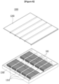
- FIG. 7 is a perspective view of a battery pack according to another embodiment of the present invention.
- FIG. 8 is an exploded perspective view of an upper pack frame of the battery pack in FIG. 7 .
- FIG. 9 is an exploded perspective view of components of the battery pack in FIG. 7 .
- a battery pack 1000 includes the above-mentioned battery modules 100. Meanwhile, one or more battery modules 100 are packaged in the pack frames 1200 and 1300, thereby constituting the battery pack 1000.
- the lower pack frame 1300 includes a plurality of module regions in which the battery modules 100 are mounted.
- the plurality of module regions may be defined by a plurality of beams 1310 extending from one side of the lower pack frame 1300 toward the other side of the lower pack frame 1300.
- the plurality of beams 1310 may extend in a vertical or horizontal direction based on a proceeding direction of a device on which the battery pack 1000 is mounted.
- the device may be a vehicle.
- the plurality of beams 1310 may extend in the vertical or horizontal direction based on a proceeding direction of the vehicle on which the battery pack 1000 is mounted.
- thermally conductive resin layers 1340 may be respectively formed in the module regions defined by the plurality of beams 1310.
- the thermally conductive resin layers 1340 may be respectively formed at positions corresponding to the battery modules 100 mounted in the module regions defined by the plurality of beams 1310.
- the thermally conductive resin layer 1340 may be formed by applying thermally conductive resin onto the lower pack frame 1300. That is, the thermally conductive resin layer 1340 may be formed by curing the thermally conductive resin applied in advance before the battery modules 100 are mounted in the module regions. Therefore, as the thermally conductive resin is cured, the lower surface of the battery module 100 and the lower pack frame 1300 may be stably fixed to each other. In addition, because a separate fixing member is not required, which makes it possible to improve the price competitiveness and increase the battery density.
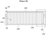
- FIG. 10 is a view illustrating a part of a cross-section taken along cutting line C-C in FIG. 7 .
- FIG. 11 is an enlarged view of a part of FIG. 10 .
- the lower surface of the battery cell stack 120 of the battery module 100 may be exposed, such that the lower surface of the battery cell stack 120 and the thermally conductive resin layer 1340 may be in contact with each other. Therefore, the heat generated in the battery cell stack 120 may be transferred directly to the thermally conductive resin layer 1340. Therefore, it is possible to further improve the performance in cooling the battery module 100 and improve the lifespan of the battery cell 110.
- an outer surface of the exterior member 150 of the battery module 100 may be in contact with the beam 1310. More specifically, the outer surface of the exterior member 150, which surrounds the two opposite lateral sides of the battery cell stack 120, may be in contact with the beams 1310. In this case, the beams 1310 may press the outer surface of the exterior member 150, which contacts with the beam 1310, against the deformation 110A in the width direction caused during the process of charging and discharging the battery pack 1000.
- the beam 1310 may be made of an elastic material.
- the elastic material may be at least any one of a steel material, such as a flat spring and a plastic injection-molded product material.
- the present invention is not limited thereto. Any material may be applied without limitation as long as the material may have elasticity capable of effectively absorbing external impact and sufficiently pressing the outer surface of the exterior member 150 of the battery module 100.
- the beams 1310 provide the elastic force to the two opposite lateral sides of the battery module 100 in the width direction of the battery module 100, i.e., the stacking direction of the battery cell stack 120. Therefore, it is possible to prevent swelling of the battery cell caused by the battery module 100 and improve the dimensional stability of the battery module.
- the above-mentioned battery module and the battery pack including the battery module may be applied to various devices.
- Examples of such devices may include transportation means such as an electric bicycle, an electric vehicle, and a hybrid vehicle, but the present invention is not limited thereto, and may be applied to various devices that may use the battery module and the battery pack including the battery module. These configurations may also belong to the scope of the present invention.
Landscapes
- Chemical & Material Sciences (AREA)
- Chemical Kinetics & Catalysis (AREA)
- Electrochemistry (AREA)
- General Chemical & Material Sciences (AREA)
- Engineering & Computer Science (AREA)
- Manufacturing & Machinery (AREA)
- Life Sciences & Earth Sciences (AREA)
- Sustainable Development (AREA)
- Sustainable Energy (AREA)
- Power Engineering (AREA)
- Transportation (AREA)
- Mechanical Engineering (AREA)
- Aviation & Aerospace Engineering (AREA)
- Battery Mounting, Suspending (AREA)
- Secondary Cells (AREA)
Applications Claiming Priority (2)
| Application Number | Priority Date | Filing Date | Title |
|---|---|---|---|
| KR1020210003182A KR102807493B1 (ko) | 2021-01-11 | 2021-01-11 | 전지 모듈 및 이를 포함하는 전지팩 |
| PCT/KR2022/000283 WO2022149899A1 (ko) | 2021-01-11 | 2022-01-07 | 전지 모듈 및 이를 포함하는 전지팩 |
Publications (3)
| Publication Number | Publication Date |
|---|---|
| EP4170798A1 true EP4170798A1 (de) | 2023-04-26 |
| EP4170798A4 EP4170798A4 (de) | 2024-08-21 |
| EP4170798B1 EP4170798B1 (de) | 2026-03-25 |
Family
ID=82358228
Family Applications (1)
| Application Number | Title | Priority Date | Filing Date |
|---|---|---|---|
| EP22736876.8A Active EP4170798B1 (de) | 2021-01-11 | 2022-01-07 | Batteriemodul und batteriepack damit |
Country Status (6)
| Country | Link |
|---|---|
| US (1) | US12586837B2 (de) |
| EP (1) | EP4170798B1 (de) |
| JP (1) | JP7531977B2 (de) |
| KR (1) | KR102807493B1 (de) |
| CN (1) | CN115885423A (de) |
| WO (1) | WO2022149899A1 (de) |
Cited By (1)
| Publication number | Priority date | Publication date | Assignee | Title |
|---|---|---|---|---|
| EP4474943A4 (de) * | 2023-04-27 | 2026-02-18 | Samsung Electronics Co Ltd | Tragbare elektronische vorrichtung mit batterie |
Families Citing this family (2)
| Publication number | Priority date | Publication date | Assignee | Title |
|---|---|---|---|---|
| US20250105427A1 (en) * | 2022-07-20 | 2025-03-27 | LG Energy Solution, LTD | Battery Pack, Cell Block Included Therein, and Vehicle Including the Same |
| KR20240028583A (ko) * | 2022-08-24 | 2024-03-05 | 주식회사 엘지에너지솔루션 | 전지 모듈 및 이를 포함하는 전지팩 |
Family Cites Families (29)
| Publication number | Priority date | Publication date | Assignee | Title |
|---|---|---|---|---|
| JP3913013B2 (ja) * | 2001-08-10 | 2007-05-09 | 松下電器産業株式会社 | 積層形マンガン乾電池 |
| KR101075283B1 (ko) * | 2009-02-26 | 2011-10-19 | 에스비리모티브 주식회사 | 이차 전지 모듈 및 그 제조 방법 |
| JP5485578B2 (ja) | 2009-04-07 | 2014-05-07 | 川崎重工業株式会社 | 密閉式角形電池を用いた電池モジュール |
| DE102011013618A1 (de) * | 2011-03-11 | 2012-09-13 | Li-Tec Battery Gmbh | Energiespeichervorrichtung |
| JP5418536B2 (ja) | 2011-04-22 | 2014-02-19 | 三菱自動車工業株式会社 | 電気機器ケース |
| CN202721242U (zh) * | 2012-06-19 | 2013-02-06 | 深圳市格瑞普电池有限公司 | 一种具有良好散热效果的锂离子电池组 |
| KR101587312B1 (ko) * | 2012-11-16 | 2016-01-21 | 주식회사 엘지화학 | 간극 충진용 스웰링 테이프 |
| KR101826861B1 (ko) | 2013-05-31 | 2018-02-08 | 주식회사 엘지화학 | 이차전지 및 이를 포함하는 전지모듈 |
| US9496588B2 (en) * | 2013-07-30 | 2016-11-15 | Johnson Controls Technology Company | Battery module with cooling features |
| KR101722183B1 (ko) | 2014-10-28 | 2017-03-31 | 주식회사 엘지화학 | 센싱블록을 이용한 배터리 모듈 고정구조 |
| KR101929529B1 (ko) | 2015-04-22 | 2018-12-14 | 주식회사 엘지화학 | 고정 프레임을 포함하는 전지모듈 및 고정 프레임을 전지모듈 상에 형성하는 방법 |
| KR102032356B1 (ko) * | 2015-12-07 | 2019-11-08 | 주식회사 엘지화학 | 전지모듈용 전압 센싱 블록 |
| KR102063938B1 (ko) * | 2016-08-12 | 2020-01-08 | 주식회사 엘지화학 | 스트랩 타입의 프레임을 구비한 배터리 모듈 및 이를 위한 프레임 어셈블리 |
| KR20180068379A (ko) | 2016-12-13 | 2018-06-22 | 현대자동차주식회사 | 전기자동차의 배터리 케이스 |
| KR20180085664A (ko) | 2017-01-19 | 2018-07-27 | 타이코에이엠피 주식회사 | 배터리 셀 센싱 장치 및 이를 포함하는 배터리 패키지 |
| KR102159347B1 (ko) | 2017-11-14 | 2020-09-23 | 주식회사 엘지화학 | 배터리 셀 가압형 엔드 플레이트와 확장형 센싱 하우징 구조가 적용된 배터리 모듈 |
| JP6948564B2 (ja) | 2017-12-12 | 2021-10-13 | トヨタ自動車株式会社 | 電池モジュール |
| KR102580847B1 (ko) * | 2018-04-26 | 2023-09-19 | 에스케이온 주식회사 | 배터리 랙 |
| KR102382382B1 (ko) | 2018-07-03 | 2022-04-01 | 주식회사 엘지에너지솔루션 | 열수축성 튜브를 포함하는 배터리 모듈 |
| KR102703855B1 (ko) | 2018-08-21 | 2024-09-05 | 에스케이온 주식회사 | 배터리 모듈 및 이의 제조방법 |
| KR102298105B1 (ko) | 2019-01-08 | 2021-09-03 | 주식회사 엘지에너지솔루션 | 스웰링 게이지를 구비한 배터리 모듈 및 이를 포함하는 배터리 팩 |
| US12230820B2 (en) | 2019-01-09 | 2025-02-18 | Byd Company Limited | Power battery pack and electric vehicle |
| CN209401761U (zh) * | 2019-04-18 | 2019-09-17 | 宁德时代新能源科技股份有限公司 | 电池模块 |
| KR102396437B1 (ko) * | 2019-06-25 | 2022-05-09 | 주식회사 엘지에너지솔루션 | 전지 모듈 및 이를 포함하는 전지팩 |
| KR20210000551A (ko) | 2019-06-25 | 2021-01-05 | 주식회사 엘지화학 | 전지 팩 및 이를 포함하는 디바이스 |
| KR102917125B1 (ko) | 2021-01-11 | 2026-01-22 | 주식회사 엘지에너지솔루션 | 전지 모듈 및 이를 포함하는 전지팩 |
| KR20220101308A (ko) | 2021-01-11 | 2022-07-19 | 주식회사 엘지에너지솔루션 | 전지 모듈, 이를 포함하는 전지팩 및 이의 제조 방법 |
| KR102813934B1 (ko) | 2021-01-11 | 2025-05-27 | 주식회사 엘지에너지솔루션 | 전지 모듈 및 이를 포함하는 전지팩 |
| KR102892922B1 (ko) | 2021-02-16 | 2025-11-27 | 주식회사 엘지에너지솔루션 | 전지 모듈 및 이를 포함하는 전지팩 |
-
2021
- 2021-01-11 KR KR1020210003182A patent/KR102807493B1/ko active Active
-
2022
- 2022-01-07 CN CN202280005622.6A patent/CN115885423A/zh active Pending
- 2022-01-07 WO PCT/KR2022/000283 patent/WO2022149899A1/ko not_active Ceased
- 2022-01-07 US US18/019,643 patent/US12586837B2/en active Active
- 2022-01-07 JP JP2023506324A patent/JP7531977B2/ja active Active
- 2022-01-07 EP EP22736876.8A patent/EP4170798B1/de active Active
Cited By (1)
| Publication number | Priority date | Publication date | Assignee | Title |
|---|---|---|---|---|
| EP4474943A4 (de) * | 2023-04-27 | 2026-02-18 | Samsung Electronics Co Ltd | Tragbare elektronische vorrichtung mit batterie |
Also Published As
| Publication number | Publication date |
|---|---|
| JP7531977B2 (ja) | 2024-08-13 |
| JP2023536870A (ja) | 2023-08-30 |
| KR20220101311A (ko) | 2022-07-19 |
| US20230291025A1 (en) | 2023-09-14 |
| US12586837B2 (en) | 2026-03-24 |
| KR102807493B1 (ko) | 2025-05-13 |
| EP4170798B1 (de) | 2026-03-25 |
| EP4170798A4 (de) | 2024-08-21 |
| CN115885423A (zh) | 2023-03-31 |
| WO2022149899A1 (ko) | 2022-07-14 |
Similar Documents
| Publication | Publication Date | Title |
|---|---|---|
| EP4199191B1 (de) | Batteriemodul und batteriepack damit | |
| EP4170798A1 (de) | Batteriemodul und batteriepack damit | |
| CN114450840B (zh) | 电池组和制造该电池组的方法 | |
| US20230299431A1 (en) | Battery cell, battery module, and battery pack including the same | |
| EP4170796A1 (de) | Batteriemodul und batteriepack damit | |
| JP2022548169A (ja) | 電池パックおよびこれを含むデバイス | |
| JP7584847B2 (ja) | 電池モジュールおよびこれを含む電池パック | |
| KR102842444B1 (ko) | 전지 모듈 및 이를 포함하는 전지 팩 | |
| EP4199216A1 (de) | Batteriemodul und batteriepack damit | |
| KR20230097684A (ko) | 전지 모듈 및 이를 포함하는 전지 팩 | |
| KR102917132B1 (ko) | 전지 모듈 및 이를 포함하는 전지 팩 | |
| CN115104218B (zh) | 电池模块以及包括该电池模块的电池组 | |
| CN220172264U (zh) | 电池模块和包括该电池模块的电池组 | |
| EP4220831A1 (de) | Batteriemodul und batteriepack damit |
Legal Events
| Date | Code | Title | Description |
|---|---|---|---|
| STAA | Information on the status of an ep patent application or granted ep patent |
Free format text: STATUS: THE INTERNATIONAL PUBLICATION HAS BEEN MADE |
|
| PUAI | Public reference made under article 153(3) epc to a published international application that has entered the european phase |
Free format text: ORIGINAL CODE: 0009012 |
|
| STAA | Information on the status of an ep patent application or granted ep patent |
Free format text: STATUS: REQUEST FOR EXAMINATION WAS MADE |
|
| 17P | Request for examination filed |
Effective date: 20230119 |
|
| AK | Designated contracting states |
Kind code of ref document: A1 Designated state(s): AL AT BE BG CH CY CZ DE DK EE ES FI FR GB GR HR HU IE IS IT LI LT LU LV MC MK MT NL NO PL PT RO RS SE SI SK SM TR |
|
| DAV | Request for validation of the european patent (deleted) | ||
| DAX | Request for extension of the european patent (deleted) | ||
| A4 | Supplementary search report drawn up and despatched |
Effective date: 20240722 |
|
| RIC1 | Information provided on ipc code assigned before grant |
Ipc: B60L 50/60 20190101ALI20240716BHEP Ipc: B60L 50/64 20190101ALI20240716BHEP Ipc: H01M 10/647 20140101ALI20240716BHEP Ipc: H01M 10/653 20140101ALI20240716BHEP Ipc: H01M 50/211 20210101ALI20240716BHEP Ipc: H01M 50/569 20210101ALI20240716BHEP Ipc: H01M 50/242 20210101AFI20240716BHEP |
|
| STAA | Information on the status of an ep patent application or granted ep patent |
Free format text: STATUS: EXAMINATION IS IN PROGRESS |
|
| 17Q | First examination report despatched |
Effective date: 20250610 |
|
| GRAP | Despatch of communication of intention to grant a patent |
Free format text: ORIGINAL CODE: EPIDOSNIGR1 |
|
| STAA | Information on the status of an ep patent application or granted ep patent |
Free format text: STATUS: GRANT OF PATENT IS INTENDED |
|
| INTG | Intention to grant announced |
Effective date: 20251112 |
|
| GRAS | Grant fee paid |
Free format text: ORIGINAL CODE: EPIDOSNIGR3 |
|
| GRAA | (expected) grant |
Free format text: ORIGINAL CODE: 0009210 |
|
| STAA | Information on the status of an ep patent application or granted ep patent |
Free format text: STATUS: THE PATENT HAS BEEN GRANTED |
|
| P01 | Opt-out of the competence of the unified patent court (upc) registered |
Free format text: CASE NUMBER: UPC_APP_0004940_4170798/2026 Effective date: 20260211 |
|
| AK | Designated contracting states |
Kind code of ref document: B1 Designated state(s): AL AT BE BG CH CY CZ DE DK EE ES FI FR GB GR HR HU IE IS IT LI LT LU LV MC MK MT NL NO PL PT RO RS SE SI SK SM TR |
|
| REG | Reference to a national code |
Ref country code: CH Ref legal event code: F10 Free format text: ST27 STATUS EVENT CODE: U-0-0-F10-F00 (AS PROVIDED BY THE NATIONAL OFFICE) Effective date: 20260325 Ref country code: GB Ref legal event code: FG4D |
|
| REG | Reference to a national code |
Ref country code: DE Ref legal event code: R096 Ref document number: 602022032987 Country of ref document: DE |
|
| REG | Reference to a national code |
Ref country code: IE Ref legal event code: FG4D |