EP4170846A2 - Système d'alimentation électrique, procédé d'alimentation électrique, appareil de commande et support de stockage informatique - Google Patents
Système d'alimentation électrique, procédé d'alimentation électrique, appareil de commande et support de stockage informatique Download PDFInfo
- Publication number
- EP4170846A2 EP4170846A2 EP22202658.5A EP22202658A EP4170846A2 EP 4170846 A2 EP4170846 A2 EP 4170846A2 EP 22202658 A EP22202658 A EP 22202658A EP 4170846 A2 EP4170846 A2 EP 4170846A2
- Authority
- EP
- European Patent Office
- Prior art keywords
- current
- switch
- module
- duration
- output
- Prior art date
- Legal status (The legal status is an assumption and is not a legal conclusion. Google has not performed a legal analysis and makes no representation as to the accuracy of the status listed.)
- Granted
Links
Images




Classifications
-
- H—ELECTRICITY
- H02—GENERATION; CONVERSION OR DISTRIBUTION OF ELECTRIC POWER
- H02J—ELECTRIC POWER NETWORKS; CIRCUIT ARRANGEMENTS OR SYSTEMS FOR SUPPLYING OR DISTRIBUTING ELECTRIC POWER; SYSTEMS FOR STORING ELECTRIC ENERGY
- H02J9/00—Circuit arrangements for emergency or stand-by power supply, e.g. for emergency lighting
- H02J9/04—Circuit arrangements for emergency or stand-by power supply, e.g. for emergency lighting in which the distribution system is disconnected from the normal source and connected to a standby source
- H02J9/06—Circuit arrangements for emergency or stand-by power supply, e.g. for emergency lighting in which the distribution system is disconnected from the normal source and connected to a standby source with automatic change-over, e.g. UPS systems
- H02J9/062—Circuit arrangements for emergency or stand-by power supply, e.g. for emergency lighting in which the distribution system is disconnected from the normal source and connected to a standby source with automatic change-over, e.g. UPS systems for AC powered loads
-
- H—ELECTRICITY
- H02—GENERATION; CONVERSION OR DISTRIBUTION OF ELECTRIC POWER
- H02J—ELECTRIC POWER NETWORKS; CIRCUIT ARRANGEMENTS OR SYSTEMS FOR SUPPLYING OR DISTRIBUTING ELECTRIC POWER; SYSTEMS FOR STORING ELECTRIC ENERGY
- H02J3/00—Circuit arrangements for AC mains or AC distribution networks
- H02J3/01—Arrangements for reducing harmonics or ripples
-
- H—ELECTRICITY
- H02—GENERATION; CONVERSION OR DISTRIBUTION OF ELECTRIC POWER
- H02J—ELECTRIC POWER NETWORKS; CIRCUIT ARRANGEMENTS OR SYSTEMS FOR SUPPLYING OR DISTRIBUTING ELECTRIC POWER; SYSTEMS FOR STORING ELECTRIC ENERGY
- H02J3/00—Circuit arrangements for AC mains or AC distribution networks
- H02J3/18—Arrangements for adjusting, eliminating or compensating reactive power in networks
-
- H—ELECTRICITY
- H02—GENERATION; CONVERSION OR DISTRIBUTION OF ELECTRIC POWER
- H02J—ELECTRIC POWER NETWORKS; CIRCUIT ARRANGEMENTS OR SYSTEMS FOR SUPPLYING OR DISTRIBUTING ELECTRIC POWER; SYSTEMS FOR STORING ELECTRIC ENERGY
- H02J3/00—Circuit arrangements for AC mains or AC distribution networks
- H02J3/28—Arrangements for balancing of the load in networks by storage of energy
- H02J3/32—Arrangements for balancing of the load in networks by storage of energy using batteries or super capacitors with converting means
-
- H—ELECTRICITY
- H02—GENERATION; CONVERSION OR DISTRIBUTION OF ELECTRIC POWER
- H02J—ELECTRIC POWER NETWORKS; CIRCUIT ARRANGEMENTS OR SYSTEMS FOR SUPPLYING OR DISTRIBUTING ELECTRIC POWER; SYSTEMS FOR STORING ELECTRIC ENERGY
- H02J3/00—Circuit arrangements for AC mains or AC distribution networks
- H02J3/38—Arrangements for feeding a single network from two or more generators or sources in parallel; Arrangements for feeding already energised networks from additional generators or sources in parallel
- H02J3/381—Dispersed generators
Definitions
- This application relates to the field of energy technologies, and in particular, to a power supply system, a power supply method, a control apparatus, and a computer storage medium.
- UPS uninterruptible power supply
- the UPS can run in an economical mode (ECO mode).
- ECO mode an economical mode
- a UPS runs in the ECO mode. If a power grid side is normal, electric energy on the power grid side is directly provided to the load by using a bypass switch module in the UPS. If the power grid side is abnormal, electric energy stored in a battery in the UPS may be provided to the load after being processed by a direct current to direct current conversion module and a direct current to alternating current conversion module.
- ECO mode power supply efficiency is high, and loss of functions of a power supply link is low.
- a power supply system may include a plurality of parallelly-connected UPSs. Because the UPSs run in the ECO mode, a large harmonic current or reactive current may be injected into the power grid at the load. As a result, the power grid may be polluted.
- the UPS in the power supply system can use the direct current to alternating current conversion module to compensate a current harmonic or reactive current in the power grid, to minimize the pollution to the power grid.
- current equalization adjustment is performed on currents provided by the plurality of UPSs in the power supply system to the load. In this process, when the UPSs use the direct current to alternating current conversion module to compensate the current harmonic or reactive current in the power grid, the pollution to the power grid is not significantly improved, and even the pollution to the power grid becomes more serious.
- This application provides a power supply system, an uninterruptible power supply, a power supply method, and a medium, which have high power supply efficiency and a high loading capability, minimize pollution to a harmonic current and a reactive current of a power grid, and do not require another component.
- this application provides a power supply system.
- the system includes: a plurality of uninterruptible power supplies UPSs.
- Each UPS in the plurality of UPSs includes at least an input terminal, a control module, a bypass switch module, a direct current to alternating current conversion module, a collection module, and an output terminal.
- An input terminal of each UPS is connected to a power grid by using a first node
- an output terminal of each UPS is connected to a load by using a second node
- the power grid is configured to provide an alternating current to each UPS.
- One terminal of the bypass switch module is connected to the input terminal, and the other terminal of the bypass switch module is connected to the output terminal.
- the bypass switch module is configured to connect the power grid to the load under control of the control module.
- the collection module is connected to a collection point, and configured to collect a current at the collection point under the control of the control module.
- the collection point is disposed between the first node and the second node.
- the collection point may be an input terminal or an output terminal of a UPS to which the control module belongs, any point between the input terminal and the first node, any point between the output terminal and the second node, or any point on a branch in which the bypass switch module is disposed between the input terminal and the output terminal.
- the direct current to alternating current conversion module is connected to the output terminal, and configured to output a current to the output terminal under the control of the control module.
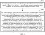
- the control module is configured to: control, in the collection period in a first duration, the control module to collect a first current at the collection point, and determine a harmonic component and/or a reactive current component of the first current; and control, in a current equalization period in the first duration, the direct current to alternating current conversion module to output a first compensation current.
- the first compensation current includes a first compensation reactive current component and/or a first quantity of first compensation harmonic components.
- the first quantity is less than or equal to a quantity of harmonic components of the first current, one first compensation reactive current component in the first quantity of first compensation harmonic components and one harmonic component of the first current have a same frequency and opposite amplitudes, and the first compensation reactive current component and the reactive current component have a same frequency and opposite amplitudes. Therefore, a reactive current component in the power grid may be compensated, and/or some or all harmonic components in the power grid may be compensated.
- the control module is further configured to adjust, in the current equalization period, duration in which the bypass switch module connects the power grid to the load, to balance currents output by output terminals of different UPSs in the plurality of UPSs, or balance currents output by bypass switch modules of the different UPSs.
- the current equalization period does not completely overlap the collection period.
- a waveform of a current in a cable in an ideal state is a sine periodic wave, and the current may be referred to as a fundamental current.
- the waveform of the current in the cable may be distorted.
- the waveform of the current in the cable is a non-sine periodic wave
- a Fourier series expansion form of the current in the cable may include a sine periodic wave (that is, a fundamental wave) and one or more harmonics in an ideal state, a waveform of each harmonic is also a sine periodic wave, and frequency is an integer multiple of the fundamental frequency.
- the harmonic may be referred to as a harmonic component in the current, a harmonic current, a current harmonic, or the like.
- the fundamental current includes an active current component and a reactive current component.
- the active current component may refer to a current generated when a load is running, and the reactive current may refer to a current generated when power is consumed by a non-load component.
- a current output by the UPS may be doped with a harmonic component.
- a harmonic component or a reactive current component determined based on a current between the output terminal and the load may not reflect a harmonic component or a reactive current component caused by the load to the power grid.
- the power supply system provided in this application collects, in the collection period in the first duration, a current output by each UPS or an output current, and determines a harmonic component and/or a reactive current component that enters each UPS and that is caused by the load.
- the power supply system performs current equalization adjustment in the current equalization period in the first duration.
- the current equalization period may not completely overlap the collection period.
- the current collected in the collection period may reflect the harmonic component or the reactive current component caused by the load to the power grid. This improves compensation effect on the harmonic component or the reactive current component in the power grid in the current equalization period.
- Each UPS outputs an equalization current in the current equalization period, and this improves the reliability of the power supply system and improves a loading capability.
- Each UPS may output compensation current to the load in the current equalization period, to compensate the harmonic component and/or the reactive current component that enters the UPS and that is caused by the load. Compensation currents output by all UPSs may compensate the harmonic component or the reactive current component caused by the load to the power grid, minimize pollution to a harmonic current and a reactive current caused by the load to the power grid, and improve quality of the power grid.
- the UPS usually includes a bypass switch module, a direct current to alternating current conversion module, a collection module, and the like.
- the control module may control the bypass switch module to output, to the load by using the output terminal, a current provided by the power grid. This enables the UPS to work in ECO mode. In the ECO mode, the control module may also control the direct current to alternating current conversion module to output the compensation current. That is, both the bypass switch module and the direct current to alternating current conversion module inside the UPS may output currents, and no additional component is required to compensate the power grid.
- control module is further configured to: control, in the collection period based on a predetermined harmonic component and/or reactive current component, the direct current to alternating current conversion module to output a second compensation current.
- the second compensation current includes a second compensation reactive current component and/or a second quantity of second compensation harmonic components.
- the second quantity is less than or equal to a quantity of predetermined harmonic components, and one second compensation reactive current component in the second quantity of second compensation harmonic components and one harmonic component of the predetermined harmonic components have a same frequency and opposite amplitudes; and the second compensation reactive current component and the predetermined reactive current component have a same frequency and opposite amplitudes.
- the predetermined harmonic component and/or reactive current component are/is determined based on a current at the collection point in a collection period in a second duration, and an end moment of the second duration is a start moment of the first duration.
- each UPS may run in a plurality of first durations
- the control module may control, in a collection period in current first duration, based on a harmonic component or a reactive current component that is determined in a first duration preceding the current first duration, the direct current to alternating current conversion module to output a compensation current that is used to compensate a harmonic component or a reactive current component determined in a previous first duration.
- the direct current to alternating current conversion module may output the compensation current in both the collection period and the current equalization period. This improves the quality of the power grid.
- each UPS in the power supply system performs the current equalization adjustment in the current equalization period.
- This application provides at least two current equalization adjustment manners. In an application process, different current equalization adjustment manners may be used depending on an actual application scenario.
- the current equalization adjustment in the power supply system may be implemented by the control module to control the duration in which the bypass switch module connects the power grid to the load, without additional component.
- the control module adjusts, based on currents output by output terminals of all the UPSs and a second current output by the output terminals of the UPSs, the duration in which the bypass switch module connects the power grid to the load. It can be learned that each UPS in the power supply system may perform the current equalization adjustment based on the currents output by the output terminals of all the UPSs, so that the currents output by the output terminals of the different UPSs are equalized.
- the control module controls the duration in which the bypass switch module connects the power grid to the load to be equal to a duration of the current equalization period. If the second current is greater than the minimum value, the control module reduces, based on duration of the current equalization period, the duration in which the bypass switch module connects the power grid to the load.
- the control module adjusts, based on currents output by bypass switch modules of all the UPSs and a third current output by the bypass switch modules, the duration in which the bypass switch module connects the power grid to the load. It can be learned that each UPS in the power supply system may perform the current equalization adjustment based on the currents output by the bypass switch modules of all the UPSs, so that the currents output by bypass switch modules of the different UPSs are equalized.
- the control module controls the duration in which the bypass switch module connects the power grid to the load to be equal to a duration of the current equalization period. If the third current is greater than the minimum value, the control module reduces, based on a duration of the current equalization period, the duration in which the bypass switch module connects the power grid to the load.
- the bypass switch module includes a first switch and a second switch. One terminal of the first switch is connected to the input terminal, and the other terminal is connected to the output terminal. The second switch is connected in parallel to the first switch.
- the control module is separately connected to control terminals of the first switch and the second switch. A current transmission direction when the first switch is turned on is opposite to a current transmission direction when the second switch is turned on.
- the collection period includes a plurality of alternating current cycles, and each alternating current cycle includes a positive half cycle and a negative half cycle. Each UPS may also supply power to the load in the collection period.
- the control module is further configured to provide, in the collection period based on a preset first conduction angle, a first control signal to the first switch, where the first conduction angle is an electrical angle between a start moment at which a level of the first control signal in the positive half cycle is a first level and an end moment of the positive half cycle; the first level is a level that is used to drive the first switch to be in an on state; the first control signal is used to drive, in a period corresponding to the first conduction angle in each positive half cycle, the first switch to connect the power grid to the load, and drive, in each negative half cycle, the first switch to be in an off state; or provide, based on a preset second conduction angle, a second control signal to the second switch, where the second conduction angle is an electrical angle between a start moment at which a level of the second control signal in the negative half cycle is a first level and an end moment of the negative half cycle; the first level is a level used to drive the second switch to be in an on state; and the second control
- the current equalization period includes a plurality of alternating current cycles.
- the control module controls, in the current equalization period, the duration in which the bypass switch module connects the power grid to the load to be equal to a duration of the current equalization period, the control module is specifically configured to: provide the first control signal to the first switch; and provide the second control signal to the second switch.
- a control mode in which the control module controls the bypass switch module in the current equalization period may maintain a control mode in which the control module controls the bypass switch module in the collection period.
- Other UPSs in the power supply system change a current output to the load.
- the current equalization period includes the plurality of alternating current cycles.
- the control module reduces, in the current equalization period based on the duration of the current equalization period, the duration in which the bypass switch module connects the power grid to the load, the control module is specifically configured to: provide, based on a third conduction angle, a third control signal to the first switch, where the third conduction angle is less than the first conduction angle, and the third conduction angle is an electrical angle between a start moment at which a level of the third control signal in the positive half cycle is the first level and the end moment of the positive half cycle; and the third control signal is used to drive, in a period corresponding to the third conduction angle in each positive half cycle, the first switch to connect the power grid to the load, and drive, in each negative half cycle, the first switch to be in the off state; or provide, based on a fourth conduction angle, a fourth control signal to the second switch, where the fourth conduction angle is less than the second conduction angle, and the fourth conduction angle
- the control module may reduce the conduction angle based on the first conduction angle, generate the third control signal by using the reduced conduction angle, and control the first switch. Therefore, a conduction moment of the first switch at the positive half cycle of each alternating current may be delayed.
- the output current may be decreased by reducing the conduction duration.
- the control module may reduce the conduction angle based on the second conduction angle, generate the fourth control signal by using the reduced conduction angle, and control the second switch. Therefore, a conduction moment of the second switch at each negative half cycle of the alternating current may be delayed.
- the output current may be decreased by reducing the conduction duration.
- the control module may change, by adjusting a conduction angle of a control signal of the first switch or the second switch, a current output by the bypass switch module to the load. It can be learned that the UPS in the power supply system may perform the current equalization adjustment without an additional component.
- the bypass switch module includes a first switch and a second switch.
- One terminal of the first switch is connected to the input terminal, and the other terminal is connected to the output terminal.
- the second switch is connected in parallel to the first switch, and the control module is separately connected to control terminals of the first switch and the second switch.
- a current transmission direction when the first switch is turned on is opposite to a current transmission direction when the second switch is turned on.
- the collection period includes a plurality of alternating current cycles. Each alternating current cycle includes a positive half cycle and a negative half cycle.
- the control module is further configured to: in the collection period, adjust, by providing a fifth control signal to the first switch, an on/off state of the first switch, to enable the first switch to connect the power grid to the load in positive half cycles of all the alternating currents, and enable the first switch to be in the off state in each negative half cycle of each alternating current; or adjust, by inputting a sixth control signal to the second switch, an on/off state of the second switch, to enable the second switch to connect the power grid to the load in all the negative half cycles, and enable the second switch to be in the off state in each positive half cycle.
- the control module controls the first switch to transmit, in all positive half cycles of the alternating current, electric energy provided by the power grid to the output terminal, controls, in each negative half cycle of the alternating current, the first switch to be in the off state; and controls the second switch to transmit, in all negative half cycles of the alternating current, the electric energy provided by the power grid to the output terminal, and controls, in each negative half cycle of the alternating current, the second switch to be in the off state in each positive half cycle.
- This design ensures that a waveform of the current output by the bypass switch control module is a sine wave in the collection period.
- the current equalization period includes a plurality of alternating current cycles.
- the control module controls, in the current equalization period, the duration in which the bypass switch module connects the power grid to the load to be equal to the duration of the current equalization period, the control module is specifically configured to: provide the fifth control signal to the first switch; and provide the sixth control signal to the second switch.
- the control mode in which the control module controls the bypass switch module in the current equalization period may maintain the control mode in which the control module controls the bypass switch module in the collection period.
- Other UPSs in the power supply system change the current output to the load.
- the current equalization period includes the plurality of alternating current cycles.
- the control module reduces, in the current equalization period based on the duration of the current equalization period, the duration in which the bypass switch module connects the power grid to the load, the control module is specifically configured to: adjust, by providing a seventh control signal to the first switch, the on/off state of the first switch, to enable the first switch to transmit, in a part of the positive half cycles of the alternating currents, electric energy provided by the power grid to the output terminal, and enable the first switch to be in the off state in each negative half cycle of the alternating current; or adjust, by providing an eighth control signal to the second switch, the on/off state of the second switch, to enable the second switch to transmit, in a part of the negative half cycles, electric energy provided by the power grid to the output terminal, and enable the second switch to be in the off state in each positive half cycle.
- control module may control, in all or a part of alternating current cycles in the current equalization period, the first switch to be in the on state in the positive half cycle and to be in the off state in the negative half cycle, and control the second switch to be in the off state in the positive half cycle and to be in the on state in the negative half cycle.
- This may enable the bypass switch module to output a current to the load in this part of alternating current cycles.
- the first switch and the second switch are in the off state. This decreases the current output by the bypass switch module in the current equalization period. It can be learned that the UPS in the power supply system may perform the current equalization adjustment without an additional component.
- this application provides a power supply method.
- the method is applied to an uninterruptible power supply UPS in a power supply system.
- the power supply system includes a plurality of uninterruptible power supplies UPSs.
- Each UPS in the plurality of UPSs includes at least an input terminal, a control module, a bypass switch module, a direct current to alternating current conversion module, a collection module, and an output terminal.
- An input terminal of each UPS is connected to a power grid by using a first node
- an output terminal of each UPS is connected to a load by using a second node
- the power grid is configured to provide an alternating current to each UPS.
- One terminal of the bypass switch module is connected to the input terminal, and the other terminal of the bypass switch module is connected to the output terminal.
- the bypass switch module is configured to connect the power grid to the load under control of the control module.
- the collection module is connected to a collection point, and configured to collect a current at the collection point under the control of the control module.
- the collection point is disposed between the first node and the second node.
- the direct current to alternating current conversion module is connected to the output terminal, and configured to output a current to the output terminal.
- the method includes: controlling, in a collection period in a first duration, the collection module to collect a first current at the collection point, and determining a harmonic component and/or a reactive current component of the first current; and controlling, in a current equalization period in the first duration, the direct current to alternating current conversion module to output a first compensation current, where the first compensation current includes a first compensation reactive current component and/or a first quantity of first compensation harmonic components, where the first quantity is less than or equal to a quantity of harmonic components of the first current, one first compensation reactive current component in the first quantity of first compensation harmonic components and one harmonic component of the first current have a same frequency and opposite amplitudes, and the first compensation reactive current component and the reactive current component have a same frequency and opposite amplitudes; and adjusting a duration in which the bypass switch module connects the power grid to the load, to balance currents output by output terminals of different UPSs in the plurality of UPSs, or balance currents output by bypass switch modules of the different UPSs, where the current equalization period does not
- the method before the controlling the direct current to alternating current conversion module to output a first compensation current, the method further includes: controlling, in the collection period based on a predetermined harmonic component and/or reactive current component, the direct current to alternating current conversion module to output a second compensation current, where the second compensation current includes a second compensation reactive current component and/or a second quantity of second compensation harmonic components, where the second quantity is less than or equal to a quantity of predetermined harmonic components, and one second compensation reactive current component in the second quantity of second compensation harmonic components and one harmonic component of the predetermined harmonic components have a same frequency and opposite amplitudes; the second compensation reactive current component and the predetermined reactive current component have a same frequency and opposite amplitudes; the predetermined harmonic component and/or reactive current component are/is determined based on a current at the collection point in a collection period in a second duration, and an end moment of the second duration is a start moment of the first duration.
- the adjusting a duration in which the bypass switch module connects the power grid to the load includes: adjusting, based on currents output by output terminals of all UPSs and a second current output by the output terminals of the UPSs, the duration in which the bypass switch module connects the power grid to the load; or adjusting, based on currents output by bypass switch modules of all the UPSs and a third current output by the bypass switch modules, the duration in which the bypass switch module connects the power grid to the load.
- the adjusting, based on currents output by output terminals of all the UPSs and a second current output by the output terminals of the UPSs, the duration in which the bypass switch module connects the power grid to the load includes: if the second current is a minimum value of the currents output by the output terminals of all the UPSs, controlling the duration in which the bypass switch module connects the power grid to the load to be equal to a duration of the current equalization period; or if the second current is greater than the minimum value, reducing, based on a duration of the current equalization period, the duration in which the bypass switch module connects the power grid to the load.
- the adjusting, based on currents output by bypass switch modules of all the UPSs and a third current output by the bypass switch modules, the duration in which the bypass switch module connects the power grid to the load includes: if the third current is a minimum value of the currents output by the bypass switch modules of all the UPSs, controlling the duration in which the bypass switch module connects the power grid to the load to be equal to a duration of the current equalization period; or if the third current is greater than the minimum value, reducing, based on a duration of the current equalization period, the duration in which the bypass switch module connects the power grid to the load.
- the bypass switch module includes a first switch and a second switch.
- One terminal of the first switch is connected to the input terminal, and the other terminal is connected to the output terminal.
- the second switch is connected in parallel to the first switch.
- a current transmission direction when the first switch is turned on is opposite to a current transmission direction when the second switch is turned on.
- the collection period induces a plurality of alternating current cycles.
- Each alternating current cycle includes a positive half cycle and a negative half cycle.
- the alternating current cycle includes a positive half cycle and a negative half cycle.
- the method further includes: providing, in the collection period based on a preset first conduction angle, a first control signal to the first switch, where the first conduction angle is an electrical angle between a start moment at which a level of the first control signal in the positive half cycle is a first level and an end moment of the positive half cycle; the first level is a level that is used to drive the first switch to be in an on state; the first control signal is used to drive, in a period corresponding to the first conduction angle in each positive half cycle, the first switch to connect the power grid to the load, and drive, in each negative half cycle, the first switch to be in an off state; or providing, based on a preset second conduction angle, a second control signal to the second switch, where the second conduction angle is an electrical angle between a start moment at which a level of the second control signal in the negative half cycle is a first level and an end moment of the negative half cycle; the first level is a level used to drive the second switch to be in an on state; and the second control signal is
- the first conduction angle is equal to an electrical angle of the positive half cycle
- the second conduction angle is equal to an electrical angle of the negative half cycle
- the current equalization period includes the plurality of alternating current cycles
- the controlling, in the current equalization period, the duration in which the bypass switch module connects the power grid to the load to be equal to a duration of the current equalization period includes: providing the first control signal to the first switch; and providing the second control signal to the second switch.
- the current equalization period includes the plurality of alternating current cycles
- the reducing, based on a duration of the current equalization period, the duration in which the bypass switch module connects the power grid to the load includes: providing, based on a third conduction angle, a third control signal to the first switch, where the third conduction angle is less than the first conduction angle, and the third conduction angle is an electrical angle between a start moment at which a level of the third control signal in the positive half cycle is the first level and the end moment of the positive half cycle; and the third control signal is used to drive, in a period corresponding to the third conduction angle in each positive half cycle, the first switch to connect the power grid to the load, and drive, in each negative half cycle, the first switch to be in the off state; or providing, based on a fourth conduction angle, a fourth control signal to the second switch, where the fourth conduction angle is less than the second conduction angle, and the fourth conduction angle is an electrical angle between a start moment at which a level
- the bypass switch module includes a first switch and a second switch.
- One terminal of the first switch is connected to the input terminal, and the other terminal is connected to the output terminal.
- the second switch is connected in parallel to the first switch.
- the control module is separately connected to control terminals of the first switch and the second switch.
- a current transmission direction when the first switch is turned on is opposite to a current transmission direction when the second switch is turned on.
- the collection period includes a plurality of alternating current cycles. Each alternating current cycle includes a positive half cycle and a negative half cycle.
- the method further includes: in the collection period, adjusting, by providing a fifth control signal to the control terminal of the first switch, an on/off state of the first switch, to enable the first switch to connect the power grid to the load in positive half cycles of all the alternating currents, and enable the first switch to be in the off state in each negative half cycle of each alternating current; or adjusting, by inputting a sixth control signal to the control terminal of the second switch, an on/off state of the second switch, to enable the second switch to connect the power grid to the load in all the negative half cycles, and enable the second switch to be in the off state in each positive half cycle.
- the current equalization period includes the plurality of alternating current cycles
- the controlling, in the current equalization period, the duration in which the bypass switch module connects the power grid to the load to be equal to a duration of the current equalization period includes: providing, by the control module, the fifth control signal to the first switch; and providing, by the control module, the sixth control signal to the second switch.
- the current equalization period includes the plurality of alternating current cycles
- the reducing, based on a duration of the current equalization period, the duration in which the bypass switch module connects the power grid to the load includes: adjusting, by providing a seventh control signal to the first switch, an on/off state of the first switch, to enable the first switch to connect the power grid to the load in a part of the positive half cycles of the alternating currents, and enable the first switch to be in the off state in each negative half cycle of each alternating current; or adjusting, by the control module, by providing an eighth control signal to the second switch, an on/off state of the second switch, to enable the second switch to connect the power grid to the load in a part of the negative half cycle, and enable the second switch to be in the off state in each positive half cycle.
- this application provides a control apparatus.
- the control apparatus is applied to an uninterruptible power supply UPS.
- the UPS includes at least an input terminal, a control module, a bypass switch module, a direct current to alternating current conversion module, a collection module, and an output terminal.
- An input terminal of each UPS is connected to a power grid by using a first node
- an output terminal of each UPS is connected to a load by using a second node
- the power grid is configured to provide an alternating current to each UPS.
- One terminal of the bypass switch module is connected to the input terminal, and the other terminal of the bypass switch module is connected to the output terminal.
- the bypass switch module is configured to connect the power grid to the load under control of the control module.
- the collection module is connected to a collection point, and configured to collect a current at the collection point under the control of the control module.
- the collection point is disposed between the first node and the second node.
- the direct current to alternating current conversion module is connected to the output terminal, and configured to output a current to the output terminal.
- the control apparatus is connected to the bypass switch module, the collection module, and the direct current to alternating current conversion module, and is configured to perform the method in any design of the second aspect.
- this application provides a computer-readable storage medium.
- the computer-readable storage medium stores computer instructions.
- the control apparatus is enabled to perform the method in any design of the second aspect.
- this application provides a computer program product.
- the storage medium stores computer instructions.
- the control apparatus is enabled to perform the method in any design of the second aspect.
- the UPS may include a bypass switch module and a direct current to alternating current conversion module, or may include an alternating current to direct current conversion module, a direct current to direct current conversion module, and a battery.
- a power grid side such as mains
- the UPS may obtain electric energy from the power grid side. After the electric energy is processed by the alternating current to direct current conversion module and the direct current to direct current conversion module, a part of the processed electric energy may be provided to the load, and the other part of the processed electric energy may be stored in the battery.
- the UPS provides power to the load. For example, electric energy stored in the battery in the UPS may be provided to the load after being processed by the direct current to direct current conversion module and the direct current to alternating current conversion module.
- a power supply system that provides power to the load may include a plurality of parallelly-connected UPSs.
- the UPSs can run in ECO mode, and a large harmonic current or reactive current may be injected into the power grid at the load. As a result, the power grid may be polluted.
- FIG. 2A , FIG. 2B , and FIG. 2C Each UPS in the power supply system may compensate a current harmonic or a reactive current in the power grid by using the direct current to alternating current conversion module, to minimize pollution to the power grid.
- impedance in a circuit that provides the power to the load by using the bypass switch module is mainly determined by a quantity of connected inductors (or resistors).
- a current output by each UPS can be equalized by controlling a quantity of inductors in the adjustable inductor unit (or a quantity of resistors in the adjustable resistor unit) in each UPS. In this design, because the adjustable inductor unit or the adjustable resistor unit is added to each UPS, costs and occupied space are increased. During current equalization, the inductor or resistor may heat up.
- the current output by each UPS to the load may include a current harmonic or a reactive current.
- each UPS compensates the current harmonic or the reactive current in the power grid by using the direct current to alternating current conversion module, the pollution to the power grid is not significantly improved.
- this application provides a power supply system that has high power supply efficiency, a high loading capability, and a good capability of minimizing the pollution to the power grid without requiring another component.
- a plurality of uninterruptible power supplies UPSs in the power supply system are connected in parallel.
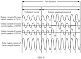
- Each UPS in the ECO mode provides an equalized load current to the load, and compensates a harmonic current and/or a reactive current of the load. For example, power is provided to the load in a collection period and a current equalization period in a first duration by using a bypass.
- Each UPS collects, in the collection period, information about a harmonic component and/or a reactive current component in an output current. The information is used as a reference value for compensating the harmonic current and/or the reactive current of the load.
- Bypass currents of each UPS may be adjusted in the current equalization period, so that an average value of the bypass currents of the UPSs in the first duration are basically the same.
- the SCR may be driven in the on state or the off state by providing a control signal to the SCR.
- a current of a control signal provided to the SCR is less than a latching current (that is, a minimum current required for maintaining the SCR to be in the on state)
- the SCR may be in the off state.
- the current of the control signal provided to the SCR is greater than or equal to the latching current
- the SCR may be in the on state.
- the SCR may be adjusted, by adjusting the control signal of the SCR, to be in the on state or the off state.
- a cycle of an alternating current signal includes a positive half cycle and a negative half cycle. Electrical angles of both the positive half cycle and the negative half cycle are 180°.
- Vk a voltage of a control signal that may drive the SCR to be in the on state.
- An electrical angle between a start moment of the positive half cycle (or the negative half cycle) and a moment at which the voltage of the control signal of the SCR is increased to Vk may be referred to as a trigger angle or a control angle ⁇
- an electrical angle between a moment at which the voltage of the control signal of the SCR reaches Vk and an end moment of the positive half cycle (or the negative half cycle) may be referred to as a conduction angle ⁇ .
- a conduction moment of the SCR in the positive half cycle may be adjusted by adjusting the control angle ⁇ or the conduction angle ⁇ of the SCR.
- the SCR1 In the positive half cycle, if a conduction angle of a control signal of the SCR1 is ⁇ 1 , the SCR1 may be driven to be in the on state in a period corresponding to ⁇ 1 .
- the conduction angle of the control signal of the SCR1 is 0, the SCR1 may be driven to be in the off state in the negative half cycle.
- an output current of the bypass switch module can be adjusted by adjusting the conduction angle of the SCR1 and the conduction angle of the SCR2.
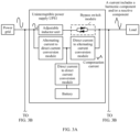
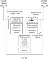
- a power supply system may include a plurality of UPSs.
- An input terminal M1 of each UPS is connected to the power grid by using a first node.
- an input terminal of each UPS is connected to the first node, and the first node is connected to the power grid.
- An output terminal M2 of each UPS is connected to the load by using a second node.
- an output terminal of each UPS is connected to the second node, and the second node is connected to the power grid. It can be learned that the first node and the second node are common terminals of a plurality of parallelly-connected UPSs.
- Each UPS may include a bypass switch module, a direct current to alternating current conversion module, and a collection module.
- Each UPS may also include an alternating current to direct current conversion module, a direct current to direct current conversion module, a battery, and a control module.
- the bypass switch module is connected between the input terminal M1 and the output terminal M2 of the UPS.
- One terminal of the alternating current to direct current conversion module is connected to the input terminal M1, and the other end is separately connected to the direct current to alternating current conversion module and the direct current to direct current conversion module. It can be seen that a branch formed by serially connecting the alternating current to direct current conversion module and the direct current to alternating current conversion module is connected in parallel to the bypass switch module.
- the bypass switch module may receive an alternating current flowing into the bypass switch module through the input terminal M1, and output the alternating current to the output terminal M2.
- the control module may control the bypass switch module, to adjust a voltage or a current of electric energy output by the bypass switch module.
- the bypass switch module may include a switch SCR1 and a switch SCR2.
- a current transmission direction when the switch SCR1 is in the on state is opposite to a current transmission direction when the switch SCR2 is in the on state.
- the switch SCR1 may be configured to connect the input terminal M1 to the output terminal M2 in the positive half cycle, to connect the power grid to the load.
- the switch SCR2 may be configured to connect the input terminal M1 to the output terminal M2 in the negative half cycle, to connect the power grid to the load.
- the control module may be connected to control terminals of the switch SCR1 and the switch SC2, and may apply the control signal to the switch SCR1, to drive the switch SCR1 to be in the on or off state. Alternatively, the control module may apply the control signal to the switch SCR2, to drive the switch SCR2 to be in the on or off state.
- the control module may adjust the conduction angle of the control signal provided to the switch SCR1 and/or the switch SCR2, to change a conduction moment of the switch SCR1 and/or the switch SCR2, and change a current output by the bypass switch module.
- the alternating current to direct current conversion module converts an alternating current input by using the input terminal M1 into the direct current, and then provides the converted current to the direct current to alternating current conversion module and the direct current to direct current conversion module.
- the control module is connected to the alternating current to direct current conversion module, to control a working status of the alternating current to direct current conversion module.
- the control module may control the alternating current to direct current conversion module to receive an alternating current flowing into the alternating current to direct current conversion module from the input terminal M1.
- the alternating current to direct current conversion module may include an alternating current to direct current conversion circuit.
- the direct current to alternating current conversion module may receive a direct current output by the alternating current to direct current conversion module or the direct current to direct current conversion module.
- the direct current to alternating current conversion module may include a direct current to alternating current conversion circuit, to convert the received direct current into an alternating current, and outputs the alternating current by using the output terminal M2.
- the direct current to alternating current conversion module may have a bidirectional processing capability, to be specific, the direct current to alternating current conversion module not only has a capability of converting a direct current into an alternating current, but also has a capability of converting an alternating current into a direct current.
- the direct current to alternating current conversion module may obtain electric energy from the output terminal M2, and the obtained electric energy may support the direct current to alternating current conversion module to convert a direct current into an alternating current.
- the control module is connected to the direct current to alternating current conversion module, to control a working state of the direct current to alternating current conversion module.
- the control module may control the direct current to alternating current conversion module to convert a direct current into an alternating current, or convert an alternating current into a direct current, or control a current for outputting a direct current.
- the direct current to alternating current conversion module may include a direct current to alternating current conversion circuit, an alternating current to direct current conversion circuit, a bidirectional conversion circuit, or the like.
- the direct current to direct current conversion module is separately connected to the alternating current to direct current conversion module and the direct current to alternating current conversion module, and the other terminal is connected to the battery.
- the direct current to alternating current conversion module has the bidirectional processing capability.
- the direct current to direct current conversion module converts the direct current output by the alternating current to direct current conversion module and transmits the processed electric energy to the battery.
- the battery stores the electric energy.
- the direct current to direct current conversion module may receive a direct current output by the battery, perform voltage conversion processing on the direct current, and output the processed direct current to the direct current to alternating current conversion module or the alternating current to direct current conversion module.
- the control module is connected to the direct current to alternating current conversion module, and may control a working mode of the direct current to direct current conversion module.
- the direct current to direct current conversion module may be controlled, by switching the working mode of the direct current to alternating current conversion module, to control the direct current to direct current conversion module to provide the electric energy to the battery or receive the electric energy provided by the battery.
- the direct current to direct current conversion module may include a direct current to direct current conversion circuit, for example, a transformer or a direct current to direct current converter.
- the collection module is connected to a collection point, and configured to collect a current at the collection point.
- the collection point may be disposed between the first node and the second node, for example, an input terminal or an output terminal of a UPS to which the control module belongs, any point between the input terminal and the first node, any point between the output terminal and the second node, or any point on a branch in which the bypass switch module is disposed between the input terminal and the output terminal.
- control module may control the bypass switch module, the alternating current to direct current conversion module, direct current to alternating current conversion module, the direct current to direct current conversion module, and the collection module, to enable the UPS to work in different modes.
- the control module may determine, based on an input voltage or current on the power grid side, whether an input on the power grid side is normal.
- the control module may adjust the UPS to be in a double conversion mode.
- the control module may control the alternating current to direct current conversion module and the direct current to alternating current conversion module, to enable the alternating current to direct current conversion module to convert all alternating currents in alternating currents that are input to the UPS into direct currents, and enable the direct current to alternating current conversion module to convert all or a part of the direct currents into alternating currents, and then provide the converted current to the load.
- the control module may also control the direct current to direct current conversion module, to enable the direct current to direct current conversion module to perform voltage conversion processing on a part of direct currents in the direct current, transmit electric energy obtained after the voltage conversion processing to the battery, and then charge a battery in the UPS when the power grid side is normal.
- the control module may control the direct current to direct current conversion module and the direct current to alternating current conversion module, to enable the direct current to direct current conversion module to perform the voltage conversion processing on a direct current provided by the battery, enable the direct current to alternating current conversion module to convert the direct current obtained after the voltage conversion processing into an alternating current, and then provide the converted current to the load after the voltage is stabilized.
- the control module may adjust the UPS to be in the ECO mode.
- the control module controls the bypass switch module, to provide, to the load by using the bypass switch module, all or a part of alternating currents in the alternating current that are input to the UPS.
- the control module may also control the alternating current to direct current conversion module and the direct current to alternating current conversion module, to enable the alternating current to direct current conversion module to convert a part of alternating current that is input to the UPS into a direct current, enable the direct current to direct current conversion module to perform the voltage conversion processing on the direct current, transmit the electric energy obtained after the voltage conversion processing the battery, and then charge the battery in the UPS when the power grid side is normal.
- control module may control the direct current to direct current conversion module and the direct current to alternating current conversion module, to enable the direct current to direct current conversion module to perform the voltage conversion processing on a direct current provided by the battery, enable the direct current to alternating current conversion module to convert the direct current obtained after the voltage conversion processing into an alternating current, and then provide the converted current to the load after the voltage is stabilized.
- Each UPS in the power supply system may be in the ECO mode.
- a control period of each UPS may be the same.
- One control period may include one or more first durations, each first duration includes a collection period and a current equalization period, and the current equalization period may not completely overlap the collection period.
- a start moment of the current equalization period may be the same as an end moment of the collection period, or a start moment of the collection period is the same as an end moment of the current equalization period, or the current equalization period does not overlap the collection period.
- a current collected by the collection module in the collection period can reflect a harmonic current and/or reactive current in the power grid. This facilitates the direct current to alternating current conversion module to output a compensation current, thereby improving quality of the power grid.
- the current equalization period and the collection period may partially overlap.
- a harmonic generated in a process of performing current equalization adjustment on output currents of different UPSs or output currents of bypass switch modules of different UPSs in the current equalization period has little impact on the harmonic current and/or reactive current in the power grid that is reflected by the current collected by the collection module in the collection period.
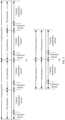
- the following uses an example in which a start moment of the current equalization period and an end moment of the collection period are a same moment. If the first duration is less than one control period, as shown in (a) in FIG. 5 , one control period may include a plurality of first durations.
- one control period may include a plurality of collection periods and a plurality of current equalization periods, and the collection periods and the current equalization periods are alternately distributed. If the first duration is equal to one control period, as shown in (b) in FIG. 5 , one control period includes one first duration. In this case, one control period includes one collection period and one current equalization period. Generally, each collection period includes a plurality of alternating current cycles, and each current equalization period includes a plurality of alternating current cycles. The current equalization period is longer than the collection period. The current equalization period is close to the first duration.
- each UPS may output a current to the load in the collection period and the current equalization period in the first duration.
- the current output to the load in the current equalization period includes an equalization current and a first compensation current.
- the first compensation current may be used to compensate a harmonic component or reactive current component, and the harmonic component or the reactive current component is determined based on the current collected at the collection point in the collection period.
- a first compensation current output by the direct current to alternating current conversion module of the UPS may include a first compensation reactive current component and/or a first quantity of first compensation harmonic components.
- the first compensation reactive current component and the reactive current component of the first current has a same frequency and opposite amplitudes. After the first compensation reactive current component is output, the first compensation reactive current component may conceal the reactive current component in the power grid, to improve the reactive current in the power grid.
- the first quantity of first compensation harmonic components in the first compensation current may be used to compensate some or all harmonic components in the power grid.
- the first quantity of first compensation harmonic components may compensate one or more harmonic components of the first current.
- the first current may include a plurality of harmonic components. Frequency of each harmonic component is an integer multiple of a fundamental frequency of the power grid, and quantities of times of harmonic components of the first current are different.
- the first quantity may be less than or equal to a quantity of harmonic components of the first current.
- one first compensation reactive current component may and one harmonic component of the first current have a same frequency and opposite amplitudes.
- harmonic components that are of the first current and that are determined by the control module are separately a harmonic component a, a harmonic component b, and a harmonic component c, the quantity of harmonic components of the first current is 3.
- the control module may control the direct current to alternating current conversion module to output the first compensation current.
- the first compensation current may include a first quantity of first harmonic components. The first quantity may be less than or equal to 3.
- the first compensation current may include one first compensation harmonic component, denoted as a first compensation harmonic component A.
- the first compensation harmonic component A and the harmonic component a may have a same frequency and opposite amplitudes. That is, the first compensation harmonic component A may compensate (or conceal) the harmonic component a, to eliminate the harmonic component a in the power grid.
- the first compensation current may include two first compensation harmonic components, denoted as a first compensation harmonic component A and a first compensation harmonic component B.
- the first compensation harmonic component A and the harmonic component a may have a same frequency and opposite amplitudes
- the first compensation harmonic component B and the harmonic component b may have a same frequency and opposite amplitudes.
- the first compensation current may include three first compensation harmonic components, denoted as a first compensation harmonic component A, a first compensation harmonic component B, and a first compensation harmonic component C.
- the first compensation harmonic component A and the harmonic component a may have a same frequency and opposite amplitudes
- the first compensation harmonic component B and the harmonic component b may have a same frequency and opposite amplitudes
- the first compensation harmonic component C and the harmonic component c may have a same frequency and opposite amplitudes.
- the collection point may be disposed between the input terminal of the UPS and the first node, or disposed between the output terminal of the UPS and the second node, to collect a harmonic component or reactive current component in a current transmitted to the power grid side by using the UPS.
- the equalization current is determined (or adjusted) based on a current output by the output terminal M2 of each UPS or a bypass output current of each UPS.
- the following uses an example in which the collection point is disposed between the output terminal of the UPS and the second node.
- the UPS may output a current (electric energy input by the power grid to the UPS) to the load in the collection period in the first duration, and determines, based on a current between the output terminal M2 and the second node, a harmonic component or reactive current component. For example, a current Ioutput between the output terminal M2 and the second node in FIG. 2A , FIG. 2B , and FIG. 2C is collected. Then, in the current equalization period in the first duration, the current output by the output terminal M2 to the load may include at least two parts.
- One part of the current is an equalization current determined based on a current between an output terminal M2 of another UPS and the second node, and the other part is a first compensation current determined based on the harmonic component or the reactive current component.
- the first compensation current may eliminate or reduce a harmonic component or reactive current component in a current between the output terminal M2 of the UPS and the second node.
- the equalization current output by each UPS may balance output currents of the UPSs in the power supply system, and therefore, power supply efficiency and a loading capability of the power supply system are improved.
- the control module may control, in the collection period, the collection module to collect the current at the collection point, that is, collect the current (may be denoted as the first current) between the output terminal M2 of the UPS and the second node.
- the control module determines a harmonic component or reactive current component of the first current, and controls the bypass switch module to transmit the electric energy provided by the power grid to the output terminal M2.
- the control module controls, in the current equalization period based on the harmonic component or the reactive current component of the first current, the direct current to alternating current conversion module to output the first compensation current, and determine, based on the current between the output terminal M2 of each UPS and the second node, whether to adjust the current output by the bypass switch module to the output terminal M2.
- control module may control, based on an on/off state of the switch SCR1 and the switch SCR2 in the bypass switch module, the bypass switch module to transmit the electric energy provided by the power grid to the output terminal M2, or control the bypass switch module to connect the power grid to the load.
- the switch SCR1 is in the off state in each negative half cycle of alternating current
- the switch SCR2 is in the off state in each positive half cycle of alternating current.
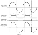
- the control module provides, in the collection period based on a preset first conduction angle ⁇ r1, a first control signal to the switch SCR1.
- the first conduction angle ⁇ r1 is an electrical angle between a start moment at which a level of a first control signal in the positive half cycle is a first level and an end moment of the positive half cycle.
- the first level may represent a level used to drive the switch SCR1 and the switch SCR2 to be in the on state.
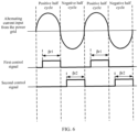
- the first control signal may drive the switch SCR1 to transmit, in a period corresponding to a first conduction angle in each positive half cycle, the electric energy provided by the power grid to the output terminal, and drive, in each negative half cycle, the switch SCR1 to be in the off state. As shown in FIG.
- the level of the first control signal in a period corresponding to a first conduction angle ⁇ r1 in a positive half cycle of each alternating current, the level of the first control signal is a first level; in a negative half cycle of each alternating current, the level of the first control signal is a second level.
- the second level is less than a minimum level that can drive the switch SCR1 and the switch SCR2 to be in the on state.
- the control module provides, in the collection period based on a preset second conduction angle ⁇ r2, the second control signal to the switch SCR2.
- the second conduction angle ⁇ r2 is an electrical angle between a start moment at which a level of a second control signal in the negative half cycle is the first level and an end moment of the negative half cycle.
- the second control signal may drive the switch SCR2 to transmit, in a period corresponding to a second conduction angle in each negative half cycle, the electric energy provided by the power grid to the output terminal, and drive, in each positive half cycle, the switch SCR2 to be in the off state. As shown in FIG.
- the level of the second control signal in the period corresponding to a second conduction angle ⁇ r2 in a negative half cycle of each alternating current, the level of the second control signal is the first level; in the positive half cycle of each alternating current, the level of the second control signal is the second level.
- the first conduction angle ⁇ r1 may be less than or equal to 180°
- the second conduction angle ⁇ r2 may be less than or equal to 180°.
- the preset first conduction angle ⁇ r1 and the preset second conduction angle ⁇ r2 may be equal to 180°, that is, equal to electrical angles of the positive half cycle and the negative half cycle.
- a level of a first control signal is the first level
- the level of the first control signal is the second level.
- a level of a second control signal in the positive half cycle of each alternating current is the second level
- a level of a second control signal in the negative half cycle of each alternating current is the first level.
- the control module performs the current equalization control on the bypass switch module in the current equalization period.
- Control modules in each UPS may communicate with each other, for example, in a wireless communication or wired communication manner.
- the control module may obtain, by communicating with another control module, information such as a current (collected in the collection period) between the output terminals of another UPS and the load.
- a manner in which the control module in the UPS obtains the information such as the current between the output terminal of the another UPS and the load includes but is not limited to a manner provided in this application, and the information may alternatively be obtained in another manner. This is not limited in this application.
- the control module performs the current equalization control on the bypass switch module in the current equalization period.
- the control module may determine, based on a current (collected by each UPS in the collection period) between the output terminal of each UPS and the second node, whether to adjust an equalization current output by the bypass switch module to the output terminal M2. This process may also be referred to as current equalization adjustment.
- Each UPS may perform the following current equalization adjustment method provided in this embodiment of this application.
- Each UPS may perform another current equalization adjustment method. This is not excessively limited in this application.
- each UPS in the power supply system may adjust, based on currents output by output terminals of all UPSs and a second current output by the output terminals of the UPSs, the duration in which the bypass switch module connects the power grid to the load.
- each UPS may control the duration in which the bypass switch module connects the power grid to the load to be equal to a duration of the current equalization period.
- the control module may control, by a control mode of the bypass switch module in the collection period, the bypass switch module in the current equalization period. That is, the control module does not change the control mode of the bypass switch module in the current equalization period.
- the control module may drive the switch SCR1 based on a first control signal provided to the switch SCR1 in the collection period, and drive the switch SCR2 based on a second control signal provided to the switch SCR2 in the collection period.
- control module may reduce, based on a duration of the current equalization period, the duration in which the bypass switch module connects the power grid to the load.
- each UPS in the power supply system may adjust, based on currents output by bypass switch modules of all UPSs and a third current output by the bypass switch modules, the duration in which the bypass switch module connects the power grid to the load.
- the control module may control the duration in which the bypass switch module connects the power grid to the load to be equal to a duration of the current equalization period. For example, the control module may control, by the control mode of the bypass switch module in the collection period, the bypass switch module in the current equalization period. That is, the control module does not change the control mode of the bypass switch module in the current equalization period.
- the control module may drive the switch SCR1 by based on the first control signal provided to the switch SCR1 in the collection period, and drive the switch SCR2 based on the second control signal provided to the switch SCR2 in the collection period.
- control module may reduce, based on a duration of the current equalization period, the duration in which the bypass switch module connects the power grid to the load.
- control module may reduce, in the duration of the current equalization period by changing a conduction angle of a control signal of each switch in the bypass switch module, the duration in which the bypass switch module connects the power grid to the load, to decrease the output current of the bypass switch module.
- the control module may provide, based on a third conduction angle ⁇ 3, the third control signal to the switch SCR1.
- the third conduction angle ⁇ 3 is less than the first conduction angle ⁇ r1, and the third conduction angle ⁇ r1 is an electrical angle between a start moment at which a level of the third control signal in the positive half cycle is the first level and an end moment of the positive half cycle.
- the third control signal may drive the switch SCR1 to transmit, in a period corresponding to a third conduction angle ⁇ 3 in each positive half cycle, the electric energy provided by the power grid to the output terminal M2, and drive, in each negative half cycle, the switch SCR1 to be in the off state.
- the control module may provide, based on a fourth conduction angle ⁇ 4, a fourth control signal to the switch SCR2.
- the fourth conduction angle ⁇ 4 is less than the second conduction angle ⁇ r2.
- the fourth conduction angle ⁇ 4 is an electrical angle between a start moment at which a level of a fourth control signal in the negative half cycle is the first level and an end moment of the negative half cycle.
- the fourth control signal is used to drive, in a period corresponding to a fourth conduction angle ⁇ 4 in each negative half cycle, the switch SCR2 to transmit the electric energy provided by the power grid to the output terminal, and drive, in each positive half cycle, the switch SCR2 to be in the off state.
- control module may change, in the current equalization period, control signals of the switch SCR1 and the switch SCR2, to decrease an equalization current output by the bypass switch module to the output terminal M2.
- the control module provides the third control signal to the switch SCR1, and provides the fourth control signal to the switch SCR2.
- the control module may determine, in a preset manner based on a difference between the second current and the minimum value of the output currents of the output terminals of the UPSs, a conduction angle in the current equalization period. For example, a smaller difference between the second current and the minimum value indicates a smaller difference between the determined third conduction angle (or the fourth conduction angle) and the determined first conduction angle (or the second conduction angle). A larger difference between the second current and the minimum value indicates a larger difference between the determined third conduction angle (or the fourth conduction angle) and the determined first conduction angle (or the second conduction angle).
- the at least one UPS may control, by the control mode of the bypass switch module in the collection period, the bypass switch module in the current equalization period.
- Other UPSs may adjust the control mode of the bypass switch module, to decrease a current output by the output terminal M2 of the UPS to the load.
- the control module may determine, in the preset manner based on a difference between the third current and the minimum value of the output currents of the bypass switch modules of all the UPSs, the conduction angle in the current equalization period. For example, a smaller difference between the third current and the minimum value indicates a smaller difference between the determined third conduction angle (or the fourth conduction angle) and the determined first conduction angle (or the second conduction angle). A larger difference between the third current and the minimum value indicates a larger difference between the determined third conduction angle (or the fourth conduction angle) and the determined first conduction angle (or the second conduction angle).
- the at least one UPS may control, by the control mode of the bypass switch module in the collection period, the bypass switch module in the current equalization period.
- Other UPSs may adjust the control mode of the bypass switch module, to decrease a current output by the bypass switch module of the UPS to the load.
- each UPS performs the current equalization adjustment in each current equalization period of the first duration.
- currents output by output terminals of UPSs in each first duration can be equalized, or the output currents of the bypass switch modules of the UPSs can be equalized.
- the power supply system includes three UPSs: a UPS1, a UPS2, and a UPS3.
- Conduction angles of control signals provided by the control module of each UPS to the switch SCR1 and the switch SCR2 in the collection period are 180°. Therefore, the waveform of the current output by the bypass switch module of each UPS to the load is a sine wave.
- Acurrent output by a bypass switch module of the UPS1 is the smallest current output by the output terminal of the bypass switch module of each UPS.
- the UPS2 changes, in the current equalization period, the conduction angles of the control signals provided to the switch SCR1 and the switch SCR2.
- a waveform of a current output by the UPS2 is not a sine wave, and a current is output only in a period corresponding to the conduction angle of the switch SCR1 and a period corresponding to the conduction angle of the switch SCR2.
- the UPS3 changes, in the current equalization period, the conduction angles of the control signals provided to the switch SCR1 and the switch SCR2.
- a waveform of a current output by the UPS3 is not a sine wave, and the current is output only in the period corresponding to the conduction angle of the switch SCR1 and the period corresponding to the conduction angle of the switch SCR2.
- the UPS1 in the current equalization period, maintains the control signals provided to the switch SCR1 and the switch SCR2 in the collection period. Because the currents output by the UPS2 and the UPS3 are changed, a waveform of a current output by the UPS1 is affected. However, a waveform of a current output by the power supply system to the load is a sine wave.
- the collection period may include a plurality of alternating current cycles
- the current equalization period may include a plurality of alternating current cycles.
- the control module controls, in all alternating current cycles in the alternating current cycles in the collection period, the bypass switch module to connect the power grid to the load.
- the control module may adjust, by providing a fifth control signal to the control terminal of the switch SCR1 in the collection period, an on/off state of the switch SCR1, to enable the switch SCR1 to transmit, in all the positive half cycles of the alternating current, the electric energy provided by the power grid to the output terminal, and enable the switch SCR1 to be in the off state in each negative half cycle of the alternating current.
- a level of the fifth control signal is the first level in the positive half cycle of each alternating current and the second level in the negative half cycle of each alternating current.
- a conduction angle of the fifth control signal may be 180°.
- the control module may adjust, by inputting a sixth control signal to the control terminal of the switch SCR2, an on/off state of the switch SCR2, to enable the switch SCR2 to transmit, in all the negative half cycles, the electric energy provided by the power grid to the output terminal, and enable the switch SCR2 to be in the off state in each positive half cycle.
- a level of the sixth control signal is the first level in the negative half cycle of each alternating current and the second level in the positive half cycle of each alternating current.
- a conduction angle of the sixth control signal may be 180°.
- each UPS in the power supply system may adjust, based on the currents output by the output terminals of all UPSs and the second current output by the output terminals of the UPSs, the duration in which the bypass switch module connects the power grid to the load.
- each UPS may control the duration in which the bypass switch module connects the power grid to the load to be equal to a duration of the current equalization period.
- the control module may control, by the control mode of the bypass switch module in the collection period, the bypass switch module in the current equalization period. That is, the control module does not change the control mode of the bypass switch module in the current equalization period.
- the control module may drive the switch SCR1 based on the fifth control signal provided to the switch SCR1 in the collection period, and drive the switch SCR2 based on the sixth control signal provided to the switch SCR2 in the collection period.
- control module may reduce, based on the duration of the current equalization period, the duration in which the bypass switch module connects the power grid to the load.
- each UPS in the power supply system may adjust, based on the currents output by bypass switch modules of all UPSs and the third current output by the bypass switch modules, the duration in which the bypass switch module connects the power grid to the load.
- the control module may control the duration in which the bypass switch module connects the power grid to the load to be equal to the duration of the current equalization period. For example, the control module may control, by the control mode of the bypass switch module in the collection period, the bypass switch module in the current equalization period. That is, the control module does not change the control mode of the bypass switch module in the current equalization period.
- the control module may drive the switch SCR1 based on the fifth control signal provided to the switch SCR1 in the collection period, and drive the switch SCR2 based on the sixth control signal provided to the switch SCR2 in the collection period.
- control module may reduce, based on the duration of the current equalization period, the duration in which the bypass switch module connects the power grid to the load.
- the control module controls, based on the duration of the current equalization period (also based on all alternating current cycles in the current equalization period), switches in a part of alternating current cycles to be in the on state, to reduce the duration in which the bypass switch module connects the power grid to the load, and decrease the current output by the bypass switch module.
- the control module may control, in a part of alternating current cycles in the alternating current cycles in the current equalization period, the bypass switch module to output the current, and control, in another part of alternating current cycles, the bypass switch module not to output the current, to decrease the duration in which the bypass switch module connects the power grid to the load, and decrease the current output by the bypass switch module to the output terminal.
- the control module may adjust, by providing a seventh control signal to the SCR1, the on/off state of the SCR1, to enable the SCR1 to transmit, in a part of the positive half cycles of the alternating current, electric energy provided by the power grid to the output terminal, and enable the SCR1 to be in the off state in each negative half cycle of the alternating current.
- the control module may control, in a positive half cycle of another alternating current cycle other than a positive half cycle of i alternating current cycles, the switch SCR1 to be in the on state, and control, in the positive half cycle of the i alternating current cycles, the switch SCR1 to be in the off state.
- the control module may adjust, by providing an eighth control signal to the SCR2, the on/off state of the SCR2, to enable the SCR2 to transmit, in a part of the negative half cycles, electric energy provided by the power grid to the output terminal, and enable the SCR2 to be in the off state in each positive half cycle.
- the control module may control, in a negative half cycle of another alternating current cycle other than a negative half cycle of j alternating current cycles, the switch SCR2 to be in the on state, and control, in the negative half cycle of the j alternating current cycles, the switch SCR2 to be in the off state.
- i is equal to j
- the j alternating current cycles are equal to the i alternating current cycles. That is, the control module may control, in a part of the alternating current cycles in the current equalization period, the switch SCR1 and the switch SCR2 are in the off state.
- each UPS performs the current equalization adjustment in each current equalization period of the first duration.
- the currents output by output terminals of UPSs in each first duration can be equalized, or the output currents of the bypass switch modules of the UPSs can be equalized.
- FIG. 8 it is assumed that the power supply system includes three UPSs: a UPS1, a UPS2, and a UPS3.
- the current output by the bypass switch module of the UPS1 is the smallest current output by the bypass switch module of each UPS.
- the current equalization period includes a plurality of alternating current cycles.
- the UPS2 controls, in a part of alternating current cycles in the current equalization period, the switch SCR1 and the switch SCR2 to be in the off state, to enable a current output by the UPS2 to the load in the part of alternating current cycles to be 0.
- the UPS2 controls, in a positive half cycle of the other part of alternating current cycles, the switch SCR1 to be in the on state, and controls, in a negative half cycle of the other part of alternating current cycles, the control switch SCR2 to be in the on state, to enable the UPS2 to input a sine current to the load in the other part of alternating current cycles.
- the UPS3 controls, in a part of alternating current cycles in the current equalization period, the switch SCR1 and the switch SCR2 to be in the off state, to enable a current output by the UPS3 to the load in the part of alternating current cycles is 0.
- the UPS3 controls, in the positive half cycle of the other part of alternating current cycles, the switch SCR1 to be in the on state, and controls, in the negative half cycle of the other part of alternating current cycles, the control switch SCR2 to be in the on state, to enable the UPS3 to input a sine current to the load in the other part of alternating current cycles.
- the UPS1, in the current equalization period maintains the control signals provided to the switch SCR1 and the switch SCR2 in the collection period.
- the waveform of the current output by the UPS1 is affected.
- the waveform of the current output by the power supply system to the load is a sine wave.
- different UPSs controls, in the alternating current cycle in the current equalization period, the control switch SCR1 and the switch SCR2 to be in the off state.
- each UPS may further control, in the current equalization period, the direct current to alternating current conversion module to output the first compensation current.
- a harmonic component and/or a reactive current component caused by the load enters each UPS.
- a harmonic component and/or a reactive current component caused by the load at each UPS may be different.
- each UPS compensates a harmonic component and/or a reactive current component that is caused by the load and enters the UPS, for example, outputs a compensation current. Compensation currents output by all the UPSs can compensate a harmonic component and/or a reactive current component caused by a load in the power grid. This minimizes the pollution to the power grid.
- the control module may determine, based on a current at a collection point in the collection period, a harmonic component and/or a reactive current component of a collected current.
- the collection point may be disposed between the first node and the second node, for example, an input terminal or an output terminal of a UPS to which the control module belongs, any point between the input terminal and the first node, any point between the output terminal and the second node, or any point on a branch in which the bypass switch module is disposed between the input terminal and the output terminal.
- the direct current to alternating current conversion module is controlled to output a first compensation current used to compensate the harmonic component and/or the reactive current component.
- the harmonic component or the reactive current component of the current collected at the collection point is mainly caused by the load, and the harmonic component or the reactive current component caused by the load enters each UPS. This design improves compensation effect of the first compensation current output by the direct current to alternating current conversion module under control of the control module on the harmonic component and/or the reactive current component, thereby minimizing the pollution to the power grid.
- the control module may control, in the collection period, the direct current to alternating current conversion module to output a second compensation current.
- the control module may control, in the collection period based on a predetermined harmonic component and/or reactive current component, the direct current to alternating current conversion module to output the second compensation current.
- the second compensation current includes a second compensation reactive current component and/or a second quantity of second compensation harmonic components.
- the second quantity may be less than or equal to a quantity of the predetermined harmonic components. Frequency of one second compensation reactive current component in the second quantity of second compensation harmonic components, and one harmonic component in the quantity of predetermined harmonic components have a same frequency and opposite amplitudes. It can be learned that each second compensation harmonic component in the second quantity may compensate some or all of the predetermined harmonic components.
- the second compensation reactive current component and the predetermined reactive current component have a same frequency and opposite amplitudes.
- the second compensation reactive current component may compensate the predetermined reactive current component.
- the predetermined harmonic component and/or reactive current component are/is determined based on a current collected at a collection point in a collection period in a second duration.
- An end moment of the second duration is a start moment of the first duration.
- an end moment of the first duration (may be referred as the second duration) in a control period 1 is a start moment of the first duration in a control period 2.
- the control module may determine the harmonic component and/or the reactive current component based on a current collected at a collection point in a collection period in the control period 1.
- the control module may control, in the collection period in the control period 2, the direct current to alternating current conversion module to output the second compensation current.
- the second compensation current may be used to compensate the harmonic component and/or the reactive current component determined based on the current collected at the collection point in the collection period in the control period 1.
- each UPS not only can output the compensation current in the current equalization period in the first duration, but also can output the compensation current in both the collection period and the current equalization period.
- this application further provides a power supply method.
- the method may be applied to a UPS in a power supply system.
- the power supply system includes a plurality of parallelly-connected UPSs.
- an input terminal of each UPS is connected to a power grid by using a first node
- an output terminal of each UPS is connected to a load by using a second node.
- the power grid is configured to provide an alternating current to each UPS. As shown in FIG. 2A , FIG. 2B , and FIG.
- the UPS includes at least a control module, a bypass switch module, a direct current to alternating current conversion module, and a collection module.
- One terminal of the bypass switch module is connected to the input terminal, and the other terminal of the bypass switch module is connected to the output terminal.
- the collection module is connected to a collection point, the collection point is disposed between the first node and the second node, and the direct current to alternating current conversion module is connected to the output terminal.
- This application further provides a control apparatus.
- the control apparatus may be disposed in a control module of the UPS.
- the power supply method may be performed by a control apparatus in each UPS in the power supply system.
- the control apparatus is connected to the bypass switch module, the collection module, and the direct current to alternating current conversion module, and is configured to perform the power supply method provided in this application. Refer to FIG. 9 .
- the power supply method may include the following steps.
- Step S101 A control apparatus controls, in a collection period in a first duration, a collection module to collect a first current at a collection point, and determines a harmonic component and/or a reactive current component of the first current.
- Step S102 The control apparatus controls, in a current equalization period in the first duration, the direct current to alternating current conversion module to output a first compensation current, where the first compensation current includes a first compensation reactive current component and/or a first quantity of first compensation harmonic components, where the first quantity is less than or equal to a quantity of harmonic components of the first current, one first compensation reactive current component in the first quantity of first compensation harmonic components and one harmonic component of the first current have a same frequency and opposite amplitudes, and the first compensation reactive current component and the reactive current component have a same frequency and opposite amplitudes; and adjusts a duration in which the bypass switch module connects the power grid to the load, to balance currents output by output terminals of different UPSs in the plurality of UPSs, or balance currents output by bypass switch modules of the different UPSs, where the current equalization period does not completely overlap the collection period.
- the bypass switch module connects the power grid to the load, to balance currents output by output terminals of different UPSs in the plurality of UPSs, or balance currents
- the control apparatus before the control apparatus controls the direct current to alternating current conversion module to output the first compensation current that is used for compensating the harmonic component and/or the reactive current component of the first current, the control apparatus further controls, in the collection period based on a predetermined harmonic component and/or reactive current component, the direct current to alternating current conversion module to output a second compensation current.
- the second compensation current includes a second compensation reactive current component and/or a second quantity of second compensation harmonic components.
- the second quantity is less than or equal to a quantity of predetermined harmonic components.
- One second compensation reactive current component in the second quantity of second compensation harmonic components and one harmonic component of the predetermined harmonic components have a same frequency and opposite amplitudes.
- the second compensation reactive current component and the predetermined reactive current component have a same frequency and opposite amplitudes. It can be learned that the second compensation current may be used to compensate for the predetermined harmonic component and/or reactive current component.
- the predetermined harmonic component and/or reactive current component are/is determined based on a current collected at a collection point in a collection period in a second duration. An end moment of the second duration is a start moment of the first duration.
- the control apparatus may perform the following processes: adjusting, based on currents output by output terminals of all UPSs and a second current output by the output terminals of the UPSs, the duration in which the bypass switch module connects the power grid to the load; or adjusting, based on currents output by bypass switch modules of all UPSs and a third current output by the bypass switch modules, the duration in which the bypass switch module connects the power grid to the load.
- control apparatus may perform the following processes:
- control apparatus may perform the following processes:
- the bypass switch module may include a first switch (for example, a switch SCR1) and a second switch (for example, a switch SCR2).
- One terminal of the first switch is connected to the input terminal, and the other terminal is connected to the output terminal.
- the second switch is connected in parallel to the first switch.
- a current transmission direction when the first switch is turned on is opposite to a current transmission direction when the second switch is turned.
- the collection period includes a plurality of alternating current cycles, and each alternating current cycle includes a positive half cycle and a negative half cycle. Generally, the alternating current cycle includes a positive half cycle and a negative half cycle.
- control apparatus may further perform the following process: providing, in the collection period based on a preset first conduction angle, a first control signal to the first switch, where the first conduction angle is an electrical angle between a start moment at which a level of the first control signal in the positive half cycle is a first level and an end moment of the positive half cycle; the first level is a level that is used to drive the first switch to be in an on state; the first control signal is used to drive, in a period corresponding to the first conduction angle in each positive half cycle, the first switch to connect the power grid to the load, and drive, in each negative half cycle, the first switch to be in an off state; or providing, based on a preset second conduction angle, a second control signal to the second switch, where the second conduction angle is an electrical angle between a start moment at which a level of the second control signal in the negative half cycle is a first level and an end moment of the negative half cycle; the first level is a level used to drive the second switch to be in
- the current equalization period includes a plurality of alternating current cycles.
- the control apparatus in the operation in which the control apparatus controls, in the current equalization period, the bypass switch module to connect the power grid to the load to be equal to a duration of the current equalization period, the control apparatus may perform the following processes: providing the first control signal to the first switch; and providing the second control signal to the second switch.
- control apparatus may perform the following processes:
- control apparatus may further be configured to: in the collection period, adjust, by providing a fifth control signal to the control terminal of the first switch, an on/off state of the first switch, to enable the first switch to connect the power grid to the load in positive half cycles of all the alternating currents, and enable the first switch to be in the off state in each negative half cycle of each alternating current; or adjust, by inputting a sixth control signal to the control terminal of the second switch, an on/off state of the second switch, to enable the second switch to connect the power grid to the load in all the negative half cycles, and enable the second switch to be in the off state in each positive half cycle.
- the current equalization period includes a plurality of alternating current cycles.
- the control apparatus may perform the following processes: The control module provides the fifth control signal to the first switch. The control module provides the sixth control signal to the second switch.
- control apparatus may perform the following processes:
- All or some of the foregoing embodiments may be implemented by using software, hardware, firmware, or any combination thereof.
- software is used to implement the embodiments, all or a part of the embodiments may be implemented in a form of a computer program product.
- the computer program product includes one or more computer instructions.
- the computer may be a general-purpose computer, a dedicated computer, a computer network, or other programmable apparatuses.
- the computer instructions may be stored in a computer-readable storage medium or may be transmitted from a computer-readable storage medium to another computer-readable storage medium.
- the computer instructions may be transmitted from a website, computer, server, or data center to another website, computer, server, or data center in a wired (for example, a coaxial cable, an optical fiber, or a digital subscriber line (DSL) or wireless (for example, infrared, radio, or microwave) manner.
- the computer-readable storage medium may be any usable medium accessible by a computer, or a data storage device, such as a server or a data center, integrating one or more usable media.
- the usable medium may be a magnetic medium (for example, a floppy disk, a hard disk, or a magnetic tape), a semiconductor medium (SSD), or the like.
- An embodiment of this application further provides a computer-readable storage medium, configured to store the method or algorithm provided in the foregoing embodiments.
- a random access memory RAM
- a flash memory a read-only memory (ROM), an EPROM memory, a non-volatile read-only memory (non-volatile ROM), a register, a hard disk, a removable magnetic disk, or a storage medium of any other form in the art.
- ROM read-only memory
- EPROM EPROM memory
- non-volatile read-only memory non-volatile read-only memory
- register a hard disk, a removable magnetic disk, or a storage medium of any other form in the art.
- the control apparatus may include a RAM memory, a flash memory, a ROM memory, an EPROM memory, a register, a hard disk, a removable magnetic disk, or a storage medium in any other form in the art, and is configured to store steps of methods or algorithms provided in embodiments of this application.
- the storage medium may be connected to a processor (or a controller) in the control apparatus, so that the processor (or the controller) may read information from the storage medium and write information to the storage medium.
- the storage medium may be further integrated into the processor (or the controller).
- These computer program instructions may also be loaded onto a computer or another programmable data processing device, so that a series of operations and steps are performed on the computer or the another programmable device, thereby generating computer-implemented processing. Therefore, the instructions executed on the computer or the another programmable device provide steps for implementing a specific function in one or more processes in the flowcharts and/or in one or more blocks in the block diagrams.
Landscapes
- Engineering & Computer Science (AREA)
- Power Engineering (AREA)
- Business, Economics & Management (AREA)
- Emergency Management (AREA)
- Supply And Distribution Of Alternating Current (AREA)
- Inverter Devices (AREA)
Applications Claiming Priority (1)
| Application Number | Priority Date | Filing Date | Title |
|---|---|---|---|
| CN202111220863.6A CN115995816A (zh) | 2021-10-20 | 2021-10-20 | 一种供电系统、供电方法、控制装置及计算机存储介质 |
Publications (3)
| Publication Number | Publication Date |
|---|---|
| EP4170846A2 true EP4170846A2 (fr) | 2023-04-26 |
| EP4170846A3 EP4170846A3 (fr) | 2023-05-03 |
| EP4170846B1 EP4170846B1 (fr) | 2025-09-03 |
Family
ID=85202090
Family Applications (1)
| Application Number | Title | Priority Date | Filing Date |
|---|---|---|---|
| EP22202658.5A Active EP4170846B1 (fr) | 2021-10-20 | 2022-10-20 | Système d'alimentation électrique, procédé d'alimentation électrique, appareil de commande et support de stockage informatique |
Country Status (3)
| Country | Link |
|---|---|
| US (1) | US12015304B2 (fr) |
| EP (1) | EP4170846B1 (fr) |
| CN (1) | CN115995816A (fr) |
Families Citing this family (2)
| Publication number | Priority date | Publication date | Assignee | Title |
|---|---|---|---|---|
| CN118630762A (zh) * | 2024-05-20 | 2024-09-10 | 华为数字能源技术有限公司 | 不间断电源系统、其供电方法和供电系统 |
| CN119966057B (zh) * | 2025-04-10 | 2025-06-06 | 浙江达航数据技术有限公司 | 异口结构下ups及电池的充放电控制方法 |
Family Cites Families (10)
| Publication number | Priority date | Publication date | Assignee | Title |
|---|---|---|---|---|
| EP1559179A4 (fr) | 2002-10-22 | 2006-07-12 | Youtility Inc | Generateur a vitesse variable hybride/convertisseur de courant d'alimentation a alimentation sans interruption |
| US8803361B2 (en) | 2011-01-19 | 2014-08-12 | Schneider Electric It Corporation | Apparatus and method for providing uninterruptible power |
| US11289940B2 (en) * | 2013-06-14 | 2022-03-29 | Abb Schweiz Ag | Systems and methods for multi-use multi-mode ups |
| CN104659899B (zh) | 2014-12-29 | 2018-08-21 | 西安华为技术有限公司 | 一种均流方法、装置及系统 |
| US10340732B2 (en) | 2015-12-04 | 2019-07-02 | Schneider Electric It Corporation | Automatic UPS bypass load sharing |
| CN107887968A (zh) | 2016-09-29 | 2018-04-06 | 易事特集团股份有限公司 | 不间断电源系统 |
| US10630104B2 (en) | 2017-04-13 | 2020-04-21 | Schneider Electric It Corporation | Automatic current balancing for power systems |
| GB201709695D0 (en) | 2017-06-19 | 2017-08-02 | Eaton Power Quality Oy | Multi-mode UPS system with an improved energy saver mode and method of operation |
| US10461577B2 (en) | 2017-08-23 | 2019-10-29 | Schneider Electric It Corporation | Inverter paralleling control system and method |
| CN109950966B (zh) | 2017-12-20 | 2023-03-14 | 台达电子工业股份有限公司 | 具均流功能的电源旁路装置及其控制方法 |
-
2021
- 2021-10-20 CN CN202111220863.6A patent/CN115995816A/zh active Pending
-
2022
- 2022-10-19 US US17/969,194 patent/US12015304B2/en active Active
- 2022-10-20 EP EP22202658.5A patent/EP4170846B1/fr active Active
Also Published As
| Publication number | Publication date |
|---|---|
| CN115995816A (zh) | 2023-04-21 |
| EP4170846A3 (fr) | 2023-05-03 |
| EP4170846B1 (fr) | 2025-09-03 |
| US20230122255A1 (en) | 2023-04-20 |
| US12015304B2 (en) | 2024-06-18 |
Similar Documents
| Publication | Publication Date | Title |
|---|---|---|
| US9385588B2 (en) | Reactive power management | |
| CN102007663B (zh) | 用于输电线控制的设备和方法 | |
| US9685887B2 (en) | Controlling power conversion systems | |
| EP4170846A2 (fr) | Système d'alimentation électrique, procédé d'alimentation électrique, appareil de commande et support de stockage informatique | |
| KR20180051432A (ko) | 충전 대기 기기 및 충전 방법 | |
| KR20180108555A (ko) | 균형 회로, 충전 대기 기기 및 충전 제어방법 | |
| CN103269117A (zh) | 多能源汇流协调控制系统及其控制方法 | |
| CN114846716A (zh) | 控制能量存储器的能量模块的接通时间 | |
| CN115693682A (zh) | 用于使用直流快速充电装置执行功率质量控制的控制器、装置和方法 | |
| CN116979608A (zh) | 一种光伏并网逆变器过压限功率控制方法及其系统 | |
| US11777337B2 (en) | Power supply system and control method thereof | |
| JP2018182872A (ja) | 電源システム、制御方法、及び制御プログラム | |
| CN116073399A (zh) | 一种并离网切换控制方法、变流装置和供电系统 | |
| CN117439031B (zh) | 射频电源保护电路及无线通信设备 | |
| US9525335B2 (en) | Controlling method and system for supporting active power factor correction loads | |
| WO2025060250A1 (fr) | Système de conversion de puissance et son procédé de commande | |
| US12119704B2 (en) | Uninterruptible power supply device | |
| CN115663898B (zh) | 一种孤网系统、储能电源控制方法、系统及存储介质 | |
| CN217692678U (zh) | 一种电网无功自动调节系统 | |
| Chen et al. | Bi-directional grid-tied inverter with predictive current control | |
| CN110838730B (zh) | 统一虚拟阻抗控制器、统一虚拟阻抗控制方法与并联系统 | |
| Raj et al. | Adaptive Power Control Topology Based PV-Battery Microgrid System | |
| CN119561350A (zh) | 一种两级功率变换器、母线电压的调节方法及相关装置 | |
| CN121923464A (zh) | 直流母线电压波动抑制方法、电力转换装置和相关设备 | |
| CN118282230A (zh) | 电压调节系统、方法和装置 |
Legal Events
| Date | Code | Title | Description |
|---|---|---|---|
| PUAI | Public reference made under article 153(3) epc to a published international application that has entered the european phase |
Free format text: ORIGINAL CODE: 0009012 |
|
| STAA | Information on the status of an ep patent application or granted ep patent |
Free format text: STATUS: THE APPLICATION HAS BEEN PUBLISHED |
|
| PUAL | Search report despatched |
Free format text: ORIGINAL CODE: 0009013 |
|
| AK | Designated contracting states |
Kind code of ref document: A2 Designated state(s): AL AT BE BG CH CY CZ DE DK EE ES FI FR GB GR HR HU IE IS IT LI LT LU LV MC ME MK MT NL NO PL PT RO RS SE SI SK SM TR |
|
| AK | Designated contracting states |
Kind code of ref document: A3 Designated state(s): AL AT BE BG CH CY CZ DE DK EE ES FI FR GB GR HR HU IE IS IT LI LT LU LV MC ME MK MT NL NO PL PT RO RS SE SI SK SM TR |
|
| RIC1 | Information provided on ipc code assigned before grant |
Ipc: H02J 9/06 20060101ALI20230329BHEP Ipc: H02J 3/38 20060101ALI20230329BHEP Ipc: H02J 3/18 20060101ALI20230329BHEP Ipc: H02J 3/01 20060101AFI20230329BHEP |
|
| STAA | Information on the status of an ep patent application or granted ep patent |
Free format text: STATUS: REQUEST FOR EXAMINATION WAS MADE |
|
| 17P | Request for examination filed |
Effective date: 20231017 |
|
| RBV | Designated contracting states (corrected) |
Designated state(s): AL AT BE BG CH CY CZ DE DK EE ES FI FR GB GR HR HU IE IS IT LI LT LU LV MC ME MK MT NL NO PL PT RO RS SE SI SK SM TR |
|
| GRAP | Despatch of communication of intention to grant a patent |
Free format text: ORIGINAL CODE: EPIDOSNIGR1 |
|
| STAA | Information on the status of an ep patent application or granted ep patent |
Free format text: STATUS: GRANT OF PATENT IS INTENDED |
|
| INTG | Intention to grant announced |
Effective date: 20250422 |
|
| GRAS | Grant fee paid |
Free format text: ORIGINAL CODE: EPIDOSNIGR3 |
|
| GRAA | (expected) grant |
Free format text: ORIGINAL CODE: 0009210 |
|
| STAA | Information on the status of an ep patent application or granted ep patent |
Free format text: STATUS: THE PATENT HAS BEEN GRANTED |
|
| AK | Designated contracting states |
Kind code of ref document: B1 Designated state(s): AL AT BE BG CH CY CZ DE DK EE ES FI FR GB GR HR HU IE IS IT LI LT LU LV MC ME MK MT NL NO PL PT RO RS SE SI SK SM TR |
|
| P01 | Opt-out of the competence of the unified patent court (upc) registered |
Free format text: CASE NUMBER: UPC_APP_1823_4170846/2025 Effective date: 20250731 |
|
| REG | Reference to a national code |
Ref country code: CH Ref legal event code: EP |
|
| REG | Reference to a national code |
Ref country code: DE Ref legal event code: R096 Ref document number: 602022020649 Country of ref document: DE |
|
| REG | Reference to a national code |
Ref country code: IE Ref legal event code: FG4D |
|
| PGFP | Annual fee paid to national office [announced via postgrant information from national office to epo] |
Ref country code: DE Payment date: 20250910 Year of fee payment: 4 |
|
| PG25 | Lapsed in a contracting state [announced via postgrant information from national office to epo] |
Ref country code: NO Free format text: LAPSE BECAUSE OF FAILURE TO SUBMIT A TRANSLATION OF THE DESCRIPTION OR TO PAY THE FEE WITHIN THE PRESCRIBED TIME-LIMIT Effective date: 20251203 |
|
| REG | Reference to a national code |
Ref country code: LT Ref legal event code: MG9D |
|
| PGFP | Annual fee paid to national office [announced via postgrant information from national office to epo] |
Ref country code: AT Payment date: 20260113 Year of fee payment: 4 |
|
| PG25 | Lapsed in a contracting state [announced via postgrant information from national office to epo] |
Ref country code: FI Free format text: LAPSE BECAUSE OF FAILURE TO SUBMIT A TRANSLATION OF THE DESCRIPTION OR TO PAY THE FEE WITHIN THE PRESCRIBED TIME-LIMIT Effective date: 20250903 |
|
| PG25 | Lapsed in a contracting state [announced via postgrant information from national office to epo] |
Ref country code: HR Free format text: LAPSE BECAUSE OF FAILURE TO SUBMIT A TRANSLATION OF THE DESCRIPTION OR TO PAY THE FEE WITHIN THE PRESCRIBED TIME-LIMIT Effective date: 20250903 |
|
| PG25 | Lapsed in a contracting state [announced via postgrant information from national office to epo] |
Ref country code: GR Free format text: LAPSE BECAUSE OF FAILURE TO SUBMIT A TRANSLATION OF THE DESCRIPTION OR TO PAY THE FEE WITHIN THE PRESCRIBED TIME-LIMIT Effective date: 20251204 |
|
| PG25 | Lapsed in a contracting state [announced via postgrant information from national office to epo] |
Ref country code: SE Free format text: LAPSE BECAUSE OF FAILURE TO SUBMIT A TRANSLATION OF THE DESCRIPTION OR TO PAY THE FEE WITHIN THE PRESCRIBED TIME-LIMIT Effective date: 20250903 |
|
| PG25 | Lapsed in a contracting state [announced via postgrant information from national office to epo] |
Ref country code: LV Free format text: LAPSE BECAUSE OF FAILURE TO SUBMIT A TRANSLATION OF THE DESCRIPTION OR TO PAY THE FEE WITHIN THE PRESCRIBED TIME-LIMIT Effective date: 20250903 |
|
| PG25 | Lapsed in a contracting state [announced via postgrant information from national office to epo] |
Ref country code: BG Free format text: LAPSE BECAUSE OF FAILURE TO SUBMIT A TRANSLATION OF THE DESCRIPTION OR TO PAY THE FEE WITHIN THE PRESCRIBED TIME-LIMIT Effective date: 20250903 Ref country code: PL Free format text: LAPSE BECAUSE OF FAILURE TO SUBMIT A TRANSLATION OF THE DESCRIPTION OR TO PAY THE FEE WITHIN THE PRESCRIBED TIME-LIMIT Effective date: 20250903 |
|
| PG25 | Lapsed in a contracting state [announced via postgrant information from national office to epo] |
Ref country code: RS Free format text: LAPSE BECAUSE OF FAILURE TO SUBMIT A TRANSLATION OF THE DESCRIPTION OR TO PAY THE FEE WITHIN THE PRESCRIBED TIME-LIMIT Effective date: 20251203 |
|
| PG25 | Lapsed in a contracting state [announced via postgrant information from national office to epo] |
Ref country code: ES Free format text: LAPSE BECAUSE OF FAILURE TO SUBMIT A TRANSLATION OF THE DESCRIPTION OR TO PAY THE FEE WITHIN THE PRESCRIBED TIME-LIMIT Effective date: 20250903 |
|
| REG | Reference to a national code |
Ref country code: AT Ref legal event code: MK05 Ref document number: 1834339 Country of ref document: AT Kind code of ref document: T Effective date: 20250903 |
|
| PG25 | Lapsed in a contracting state [announced via postgrant information from national office to epo] |
Ref country code: NL Free format text: LAPSE BECAUSE OF FAILURE TO SUBMIT A TRANSLATION OF THE DESCRIPTION OR TO PAY THE FEE WITHIN THE PRESCRIBED TIME-LIMIT Effective date: 20250903 |
|
| PG25 | Lapsed in a contracting state [announced via postgrant information from national office to epo] |
Ref country code: SM Free format text: LAPSE BECAUSE OF FAILURE TO SUBMIT A TRANSLATION OF THE DESCRIPTION OR TO PAY THE FEE WITHIN THE PRESCRIBED TIME-LIMIT Effective date: 20250903 |
|
| PG25 | Lapsed in a contracting state [announced via postgrant information from national office to epo] |
Ref country code: AT Free format text: LAPSE BECAUSE OF FAILURE TO SUBMIT A TRANSLATION OF THE DESCRIPTION OR TO PAY THE FEE WITHIN THE PRESCRIBED TIME-LIMIT Effective date: 20250903 |
|
| PG25 | Lapsed in a contracting state [announced via postgrant information from national office to epo] |
Ref country code: RO Free format text: LAPSE BECAUSE OF FAILURE TO SUBMIT A TRANSLATION OF THE DESCRIPTION OR TO PAY THE FEE WITHIN THE PRESCRIBED TIME-LIMIT Effective date: 20250903 Ref country code: IT Free format text: LAPSE BECAUSE OF FAILURE TO SUBMIT A TRANSLATION OF THE DESCRIPTION OR TO PAY THE FEE WITHIN THE PRESCRIBED TIME-LIMIT Effective date: 20250903 |
|
| PG25 | Lapsed in a contracting state [announced via postgrant information from national office to epo] |
Ref country code: IS Free format text: LAPSE BECAUSE OF FAILURE TO SUBMIT A TRANSLATION OF THE DESCRIPTION OR TO PAY THE FEE WITHIN THE PRESCRIBED TIME-LIMIT Effective date: 20260103 |
|
| PG25 | Lapsed in a contracting state [announced via postgrant information from national office to epo] |
Ref country code: PT Free format text: LAPSE BECAUSE OF FAILURE TO SUBMIT A TRANSLATION OF THE DESCRIPTION OR TO PAY THE FEE WITHIN THE PRESCRIBED TIME-LIMIT Effective date: 20260105 Ref country code: CZ Free format text: LAPSE BECAUSE OF FAILURE TO SUBMIT A TRANSLATION OF THE DESCRIPTION OR TO PAY THE FEE WITHIN THE PRESCRIBED TIME-LIMIT Effective date: 20250903 |
|
| PG25 | Lapsed in a contracting state [announced via postgrant information from national office to epo] |
Ref country code: SK Free format text: LAPSE BECAUSE OF FAILURE TO SUBMIT A TRANSLATION OF THE DESCRIPTION OR TO PAY THE FEE WITHIN THE PRESCRIBED TIME-LIMIT Effective date: 20250903 Ref country code: EE Free format text: LAPSE BECAUSE OF FAILURE TO SUBMIT A TRANSLATION OF THE DESCRIPTION OR TO PAY THE FEE WITHIN THE PRESCRIBED TIME-LIMIT Effective date: 20250903 |