EP4170884A1 - Wandler zur durchführung von gleichstromumwandlung und verfahren zur steuerung davon - Google Patents
Wandler zur durchführung von gleichstromumwandlung und verfahren zur steuerung davon Download PDFInfo
- Publication number
- EP4170884A1 EP4170884A1 EP22807647.7A EP22807647A EP4170884A1 EP 4170884 A1 EP4170884 A1 EP 4170884A1 EP 22807647 A EP22807647 A EP 22807647A EP 4170884 A1 EP4170884 A1 EP 4170884A1
- Authority
- EP
- European Patent Office
- Prior art keywords
- battery
- converter
- input switch
- sources
- battery sources
- Prior art date
- Legal status (The legal status is an assumption and is not a legal conclusion. Google has not performed a legal analysis and makes no representation as to the accuracy of the status listed.)
- Pending
Links
Images


Classifications
-
- H—ELECTRICITY
- H02—GENERATION; CONVERSION OR DISTRIBUTION OF ELECTRIC POWER
- H02M—APPARATUS FOR CONVERSION BETWEEN AC AND AC, BETWEEN AC AND DC, OR BETWEEN DC AND DC, AND FOR USE WITH MAINS OR SIMILAR POWER SUPPLY SYSTEMS; CONVERSION OF DC OR AC INPUT POWER INTO SURGE OUTPUT POWER; CONTROL OR REGULATION THEREOF
- H02M1/00—Details of apparatus for conversion
- H02M1/10—Arrangements incorporating converting means for enabling loads to be operated at will from different kinds of power supplies, e.g. from AC or DC
-
- H—ELECTRICITY
- H02—GENERATION; CONVERSION OR DISTRIBUTION OF ELECTRIC POWER
- H02J—ELECTRIC POWER NETWORKS; CIRCUIT ARRANGEMENTS OR SYSTEMS FOR SUPPLYING OR DISTRIBUTING ELECTRIC POWER; SYSTEMS FOR STORING ELECTRIC ENERGY
- H02J3/00—Circuit arrangements for AC mains or AC distribution networks
- H02J3/28—Arrangements for balancing of the load in networks by storage of energy
- H02J3/32—Arrangements for balancing of the load in networks by storage of energy using batteries or super capacitors with converting means
-
- H—ELECTRICITY
- H02—GENERATION; CONVERSION OR DISTRIBUTION OF ELECTRIC POWER
- H02J—ELECTRIC POWER NETWORKS; CIRCUIT ARRANGEMENTS OR SYSTEMS FOR SUPPLYING OR DISTRIBUTING ELECTRIC POWER; SYSTEMS FOR STORING ELECTRIC ENERGY
- H02J7/00—Circuit arrangements for charging or discharging batteries or for supplying loads from batteries
- H02J7/50—Circuit arrangements for charging or discharging batteries or for supplying loads from batteries acting upon multiple batteries simultaneously or sequentially
-
- H—ELECTRICITY
- H02—GENERATION; CONVERSION OR DISTRIBUTION OF ELECTRIC POWER
- H02J—ELECTRIC POWER NETWORKS; CIRCUIT ARRANGEMENTS OR SYSTEMS FOR SUPPLYING OR DISTRIBUTING ELECTRIC POWER; SYSTEMS FOR STORING ELECTRIC ENERGY
- H02J7/00—Circuit arrangements for charging or discharging batteries or for supplying loads from batteries
- H02J7/90—Regulation of charging or discharging current or voltage
-
- H—ELECTRICITY
- H02—GENERATION; CONVERSION OR DISTRIBUTION OF ELECTRIC POWER
- H02M—APPARATUS FOR CONVERSION BETWEEN AC AND AC, BETWEEN AC AND DC, OR BETWEEN DC AND DC, AND FOR USE WITH MAINS OR SIMILAR POWER SUPPLY SYSTEMS; CONVERSION OF DC OR AC INPUT POWER INTO SURGE OUTPUT POWER; CONTROL OR REGULATION THEREOF
- H02M3/00—Conversion of DC power input into DC power output
- H02M3/22—Conversion of DC power input into DC power output with intermediate conversion into AC
- H02M3/24—Conversion of DC power input into DC power output with intermediate conversion into AC by static converters
- H02M3/28—Conversion of DC power input into DC power output with intermediate conversion into AC by static converters using discharge tubes with control electrode or semiconductor devices with control electrode to produce the intermediate AC
- H02M3/325—Conversion of DC power input into DC power output with intermediate conversion into AC by static converters using discharge tubes with control electrode or semiconductor devices with control electrode to produce the intermediate AC using devices of a triode or a transistor type requiring continuous application of a control signal
- H02M3/335—Conversion of DC power input into DC power output with intermediate conversion into AC by static converters using discharge tubes with control electrode or semiconductor devices with control electrode to produce the intermediate AC using devices of a triode or a transistor type requiring continuous application of a control signal using semiconductor devices only
- H02M3/33569—Conversion of DC power input into DC power output with intermediate conversion into AC by static converters using discharge tubes with control electrode or semiconductor devices with control electrode to produce the intermediate AC using devices of a triode or a transistor type requiring continuous application of a control signal using semiconductor devices only having several active switching elements
- H02M3/33573—Full-bridge at primary side of an isolation transformer
-
- H—ELECTRICITY
- H02—GENERATION; CONVERSION OR DISTRIBUTION OF ELECTRIC POWER
- H02M—APPARATUS FOR CONVERSION BETWEEN AC AND AC, BETWEEN AC AND DC, OR BETWEEN DC AND DC, AND FOR USE WITH MAINS OR SIMILAR POWER SUPPLY SYSTEMS; CONVERSION OF DC OR AC INPUT POWER INTO SURGE OUTPUT POWER; CONTROL OR REGULATION THEREOF
- H02M3/00—Conversion of DC power input into DC power output
- H02M3/22—Conversion of DC power input into DC power output with intermediate conversion into AC
- H02M3/24—Conversion of DC power input into DC power output with intermediate conversion into AC by static converters
- H02M3/28—Conversion of DC power input into DC power output with intermediate conversion into AC by static converters using discharge tubes with control electrode or semiconductor devices with control electrode to produce the intermediate AC
- H02M3/325—Conversion of DC power input into DC power output with intermediate conversion into AC by static converters using discharge tubes with control electrode or semiconductor devices with control electrode to produce the intermediate AC using devices of a triode or a transistor type requiring continuous application of a control signal
- H02M3/335—Conversion of DC power input into DC power output with intermediate conversion into AC by static converters using discharge tubes with control electrode or semiconductor devices with control electrode to produce the intermediate AC using devices of a triode or a transistor type requiring continuous application of a control signal using semiconductor devices only
- H02M3/33569—Conversion of DC power input into DC power output with intermediate conversion into AC by static converters using discharge tubes with control electrode or semiconductor devices with control electrode to produce the intermediate AC using devices of a triode or a transistor type requiring continuous application of a control signal using semiconductor devices only having several active switching elements
- H02M3/33576—Conversion of DC power input into DC power output with intermediate conversion into AC by static converters using discharge tubes with control electrode or semiconductor devices with control electrode to produce the intermediate AC using devices of a triode or a transistor type requiring continuous application of a control signal using semiconductor devices only having several active switching elements having at least one active switching element at the secondary side of an isolation transformer
- H02M3/33584—Bidirectional converters
-
- H—ELECTRICITY
- H02—GENERATION; CONVERSION OR DISTRIBUTION OF ELECTRIC POWER
- H02J—ELECTRIC POWER NETWORKS; CIRCUIT ARRANGEMENTS OR SYSTEMS FOR SUPPLYING OR DISTRIBUTING ELECTRIC POWER; SYSTEMS FOR STORING ELECTRIC ENERGY
- H02J2207/00—Details of circuit arrangements for charging or discharging batteries or supplying loads from batteries
- H02J2207/20—Charging or discharging characterised by the power electronics converter
-
- H—ELECTRICITY
- H02—GENERATION; CONVERSION OR DISTRIBUTION OF ELECTRIC POWER
- H02M—APPARATUS FOR CONVERSION BETWEEN AC AND AC, BETWEEN AC AND DC, OR BETWEEN DC AND DC, AND FOR USE WITH MAINS OR SIMILAR POWER SUPPLY SYSTEMS; CONVERSION OF DC OR AC INPUT POWER INTO SURGE OUTPUT POWER; CONTROL OR REGULATION THEREOF
- H02M3/00—Conversion of DC power input into DC power output
- H02M3/22—Conversion of DC power input into DC power output with intermediate conversion into AC
- H02M3/24—Conversion of DC power input into DC power output with intermediate conversion into AC by static converters
- H02M3/28—Conversion of DC power input into DC power output with intermediate conversion into AC by static converters using discharge tubes with control electrode or semiconductor devices with control electrode to produce the intermediate AC
- H02M3/285—Single converters with a plurality of output stages connected in parallel
-
- H—ELECTRICITY
- H02—GENERATION; CONVERSION OR DISTRIBUTION OF ELECTRIC POWER
- H02M—APPARATUS FOR CONVERSION BETWEEN AC AND AC, BETWEEN AC AND DC, OR BETWEEN DC AND DC, AND FOR USE WITH MAINS OR SIMILAR POWER SUPPLY SYSTEMS; CONVERSION OF DC OR AC INPUT POWER INTO SURGE OUTPUT POWER; CONTROL OR REGULATION THEREOF
- H02M3/00—Conversion of DC power input into DC power output
- H02M3/22—Conversion of DC power input into DC power output with intermediate conversion into AC
- H02M3/24—Conversion of DC power input into DC power output with intermediate conversion into AC by static converters
- H02M3/28—Conversion of DC power input into DC power output with intermediate conversion into AC by static converters using discharge tubes with control electrode or semiconductor devices with control electrode to produce the intermediate AC
- H02M3/325—Conversion of DC power input into DC power output with intermediate conversion into AC by static converters using discharge tubes with control electrode or semiconductor devices with control electrode to produce the intermediate AC using devices of a triode or a transistor type requiring continuous application of a control signal
- H02M3/335—Conversion of DC power input into DC power output with intermediate conversion into AC by static converters using discharge tubes with control electrode or semiconductor devices with control electrode to produce the intermediate AC using devices of a triode or a transistor type requiring continuous application of a control signal using semiconductor devices only
- H02M3/337—Conversion of DC power input into DC power output with intermediate conversion into AC by static converters using discharge tubes with control electrode or semiconductor devices with control electrode to produce the intermediate AC using devices of a triode or a transistor type requiring continuous application of a control signal using semiconductor devices only in push-pull configuration
- H02M3/3372—Conversion of DC power input into DC power output with intermediate conversion into AC by static converters using discharge tubes with control electrode or semiconductor devices with control electrode to produce the intermediate AC using devices of a triode or a transistor type requiring continuous application of a control signal using semiconductor devices only in push-pull configuration of the parallel type
Definitions
- the present invention relates to a converter that performs DC-DC conversion, and more particularly, to a converter positioned between a series of batteries and a power conversion system to perform DC-DC conversion and a method for controlling the same.
- An energy storage system relates to renewable energy, a battery that stores electric power, and grid power. Recently, as the spread of smart grid and renewable energy is expanding and the efficiency and the stability of the power system are emphasized, a demand for energy storage systems for power supply and demand control and power quality improvement is increasing. Depending on a purpose of use, energy storage systems may have different output and capacity. In order to configure a large-capacity energy storage system, a plurality of battery systems may be connected.
- An energy storage system may include a battery section consisting of a plurality of batteries, a battery management system (BMS) for battery management, a power conversion system (PCS), an energy management system (EMS), and a DC-DC converter.
- BMS battery management system
- PCS power conversion system
- EMS energy management system
- DC-DC converter DC-DC converter
- a DC-DC converter that performs DC-DC conversion between a battery and a power conversion system
- the design of a transformer is closely related to cost, efficiency, and a size of the entire system.
- a DC-DC converter having a plurality of input sources has a structure in which a respective coil is allocated to each input source.
- each input terminal is insulated for safety reasons, which increases sizes and costs of the transformer and the converter.
- the structure of the transformer becomes a negative factor in the efficiency and the size, and thus, the converter design in a typical DC-DC converter needs to be improved.
- embodiments according to an object of the present disclosure provide a DC-DC converter having one primary coil for a plurality of battery sources.
- embodiments according to another object of the present disclosure provide a method for controlling the DC-DC converter having one primary coil for a plurality of battery sources.
- embodiments according to yet another object of the present disclosure provide an energy storage device.
- a DC-DC converter is located between a plurality of batteries and a power conversion system, and comprises a primary coil connected to a plurality of battery sources and a secondary coil connected to a load through an output switch set, wherein the primary coil may be connected to the plurality of battery sources through a plurality of input switch sets corresponding to the plurality of battery sources.
- operations of the plurality of input switch sets may be controlled by a controller connected to the converter so that only one output of the plurality of battery sources is transmitted to the primary coil.
- each battery source may be a battery pack, a battery rack, a battery unit, or a battery cell.
- the load may include the power conversion system.
- the converter may be configured to perform DC-DC conversion using one input switch set in operation among the plurality of input switch sets corresponding to the plurality of battery sources and the output switch set connected to the load during one period of time.
- the converter may be configured to convert output from the power conversion system to a voltage level required by the plurality of batteries in a charging mode, and may be configured to convert output from the plurality of batteries connected to one input switch set in operation into a DC link voltage which is a voltage level required by the power conversion system in a discharging mode.
- a method for controlling a converter by a controller interworking with the converter positioned between a plurality of batteries and a power conversion system may comprise determining a battery source to be operated in a certain period of time among a plurality of battery sources connected to the converter; activating one input switch set corresponding to the battery source in operation and deactivating the other input switch sets corresponding to the other battery sources; and controlling the converter to perform DC-DC conversion.
- the activating one input switch set corresponding to the battery source in operation and deactivating the other input switch sets corresponding to the other battery sources may comprise controlling a plurality of input switch sets connected to the plurality of battery sources so that only the output of input switch set corresponding to the battery source in operation is transmitted to the primary coil of the converter.
- each battery source may be a battery pack, a battery rack, a battery unit, or a battery cell.
- controlling the converter to perform DC-DC conversion may comprise controlling the converter to perform DC-DC conversion using one input switch set in operation among a plurality of input switch sets corresponding to the plurality of battery sources and an output switch set connected to a load during one period of time.
- controlling the converter to perform DC-DC conversion may comprise converting output from the power conversion system to a voltage level required by the plurality of batteries in a charging mode.
- controlling the converter to perform DC-DC conversion may comprise converting power output from the plurality of batteries connected to the input switch set in operation into a DC link voltage which is a voltage level required by the power conversion system in a discharging mode.
- an energy storage device may comprise a plurality of battery sources; a DC-DC converter including one primary coil connected to the plurality of battery sources and a secondary coil connected to a load; and a controller configured to control the DC-DC converter such that the primary coil transmits power from one of the plurality of battery sources to the load.
- the DC-DC converter may include a plurality of input switch sets respectively connected to the plurality of battery sources and one input switch set among the plurality of input switch sets may be activated during one period of time under the control of the controller.
- the safety function secured through insulation previously can be secured through switching among battery sources using operation control of the switch sets.
- first, second, A, B, and the like may be used herein to describe various elements, these elements should not be limited by these terms. These terms are only used to distinguish one element from another. For example, a first element could be termed a second element, and, similarly, a second element could be termed a first element, without departing from the scope of the present invention.
- the term "and/or" includes combinations of a plurality of associated listed items or any of the plurality of associated listed items.
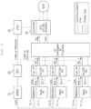
- FIG. 1 is a block diagram of a typical energy storage system having an individual DC-DC converter for each battery rack.
- a battery rack As to battery that serves to store energy in an energy storage system, typically a plurality of battery modules may form a battery rack and a plurality of battery racks 11-1, 11-2, 11-n may form a battery bank.
- a battery rack may be referred to as a battery pack.
- a battery management system may be installed in each of a battery module, a battery rack, and a battery bank.
- each RBMS (Rack BMS) 12-1, 12-2, ... , 12-n manages each battery rack
- BBMS Bank BMS (Bank BMS) (10) may control the entire battery bank including battery racks.
- the BBMS 10 may monitor a current, a voltage, and a temperature of the battery bank, calculate a state of charge (SOC) based on monitoring results, and control charging and discharging of the batteries.
- SOC state of charge
- each of the RBMS 12-1, 12-2, ... , 12-n monitors a current, a voltage and a temperature of each battery rack, calculates SOC based on the monitoring results, and controls charging and discharging of the batteries.
- a battery section controller (BSC) 20 is located in each battery section which includes a plurality of batteries and peripheral circuits, and devices to monitor and control objects such as a voltage, a current, a temperature, and a circuit breaker.
- the power conversion system (PCS) 40 installed in each battery section controls the power supplied from the outside and the power supplied from the battery section to the outside, therby controlling charging and discharging of the battery.
- the power convertion system may include a DC/AC inverter.
- An Energy Management System (EMS) 20 connected to the power conversion system may control the output of the power conversion system based on the monitoring and control results of the battery management system or the battery section controller.
- battery rack 1 (11-1) is connected to DC-DC converter #1 (12-1)
- battery rack 2 (11-2) is connected to DC-DC converter #2
- battery rack n(11-n) is connected to DC-DC converter #n(12-n).
- a respective DC-DC converter corresponding to each battery rack is used.
- the output of the DC-DC converter corresponding to each battery rack is collected through a DC Switchgear & Protector and is forwarded to the power conversion system 40.
- the DC-DC converter may convert the power stored in the battery into a voltage level required by the PCS 40 in a discharging mode, wherein the voltage level is a DC link voltage. Meanwhile, in a charging mode, the DC-DC converter may convert power output from the PCS 40 to a voltage level required by the battery which is a charging voltage.
- the RBMS 12-1, 12-2, ..., 12-n, the BBMS 10, the BSC 20, the EMS 30, and the PCS controller may communicate using CAN (Controller Area Network) or Ethernet.
- CAN Controller Area Network
- Ethernet Ethernet
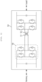
- FIG. 2 is a simplified circuit diagram of a typical DC-DC converter.
- the DC-DC converter may be a bidirectional converter, wherein, when conversion is performed from the battery to the load direction, the input of the DC-DC converter may be connected to the battery (battery unit, battery rack or battery pack) and the output of the DC-DC converter may be connected to the load.
- the converter in FIG. 2 shows an example of a full-bridge converter.
- the input terminal includes a capacitor, an input switching set 58 , and a primary coil 51
- the output terminal includes a secondary coil 52, an output switching set and a capacitor.
- FIG. 3 is a simplified circuit diagram of a typical DC-DC converter having multiple input sources.
- the converter in FIG. 3 shows an example of a full-bridge converter in which three battery sources are connected to the input terminal of the converter.
- the converter 60 shown in FIG. 3 includes a capacitor, input switch sets (switch set 1, switch set 2, ..., switch set n) and primary coils 51-1, 51-2, and 51-3 for battery sources. That is, for each of the batterries, a corresponding input switch set and a corresponding primary coil are arranged and used. In this case, it is common for each input terminal to be insulated for safety reasons.
- the output terminal of the converter includes a secondary coil 52, a common output switch set, and a capacitor.
- a separate converter is used for each individual battery source (a battery pack, a battery rack, or a battery cell) (as shown in FIG. 2 ) or a separate primary coil for each battery unit is used even though one converter for a multiple battery units is used (as shown in FIG. 3 ). That is, in both cases, a separate primary-coil is used for each battery source, so that a plurality of primary coils are used for a plurality of battery sources.
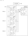
- FIG. 4 is a schematic configuration diagram of an energy storage device according to an embodiment of the present invention.
- An energy storage device comprises a plurality of battery sources; a DC-DC converter 300 including one primary coil connected to a plurality of battery sources and a secondary coil connected to a load; and a controller 400 configured to control the DC-DC converter such that the primary coil transmits power from one of the plurality of battery sources to the load.
- te DC-DC converter may include a plurality of switch sets respectively connected to the plurality of battery sources, and only one switch set among the plurality of switch sets may be activated during a period of time under the control of the controller.
- the DC-DC converter to which the present invention is applied may be a bidirectional converter, wherein, when conversion is performed from the battery to the load direction, the input of the DC-DC converter may be connected to the battery (battery unit, battery rack or battery pack) and the output of the DC-DC converter may be connected to the load.
- the left side of the converter in FIG. 4 which is a battery side
- the right side of the converter, which is a load side is referred to as an output or secondary side.
- the input and the output may be described in reverse compared to a case when discharging occurs from the battery to the load.
- Examples of the DC-DC converter to which the present invention can be applied include, in addition to a full-bridge converter, other types of converters such as a half-bridge converter or a flyback converter. Details of these converters may have different configurations in terms of internal circuits compared to a full-bridge converter. Somehow, a half-bridge converter or a flyback converter may include at least one of a primary coil, a secondary coil, and switch sets or circuits connected to each coil.
- FIG. 4 shows an embodiment in which the converter 300 according to the present invention is a full-bridge converter.
- the DC-DC converter is located between a plurality of batteries (battery 1, battery 2, ..., battery n) and a power conversion system.
- the coverter is configured to perform DC-DC convertion and to have a plurality of batteries as a plurality of inputs and have one output connected to a load.
- Each battery may be connected to an individual switch set, for example, battery 1 may be connected to switch set 1 (311), battery 2 may be connected to switch set 2 (312), and battery n may be connected to switch set n (313).
- switch set 1, switch set 2, and switch set n may be connected to one primary coil 330. That is, the DC-DC converter according to the present invention has a single primary coil for a plurality of battery sources as input. Accordingly, in a transformer structure as shown in FIG. 4 , one primary coil 330 on the primary side and one secondary coil 350 on the secondary side are arragned. The secondary coil 350 may be connected to a load through a common switch set of the output terminal.
- the DC-DC converter is configured to include a primary coil connected to a plurality of battery sources; and a secondary coil connected to a load through an output switch set.
- the primary coil is connected to the plurality of battery sources through a plurality of input switch sets corresponding to the plurality of battery sources.
- each battery source may be a battery pack, a battery rack, a battery unit, or a battery cell.
- the converter according to another embodiment of the present invention may include a primary coil connected to a plurality of battery sources; a plurality of switch sets connected to each of the plurality of battery sources and connected to the primary coil; and a secondary coil connected to a load through an output switch set.
- operation control is required for preventing power circulation between a plurality of battery sources.
- switching operation control by the controller 400 connected to the DC-DC converter 300 may be performed.
- the controller 400 interworking with the DC-DC converter controls switching for each battery source.
- the controller 400 is connected to input switch sets, each corresponding to respective battery source, to control switching operation of each input switch set.
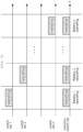
- FIG. 5 is a conceptual diagram of a switching operation of a DC-DC converter according to an embodiment of the present invention.
- the graph in FIG. 5 shows operations of each switch set in periods of time.
- One common switch set is arranged at the output terminal of the converter and operates accordingly when any of the battery sources at the input terminal operates, so that a corresponding battery source performs charge/discharge operation.
- a switch set in operation means that high-speed switching by the switch set for DC-DC conversion of power from a battery source is being performed.
- a DC-DC converter is configured to perform DC-DC conversion using one input switch set among a plurality of input switch sets corresponding to a plurality of battery sources and an output switch set connected to a load during one time period.
- the DC-DC converter may convert power output from a power conversion system to a voltage level required by the battery.
- the DC-DC converter may convert output from a battery connected to one input switch set in operation into a DC link voltage that is a voltage level required by the power conversion system.
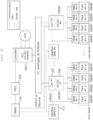
- FIG. 6 is a block diagram of an energy storage system to which a DC-DC converter according to an embodiment of the present invention is applied.
- FIG. 6 shows an energy storage system including a DC-DC converter with battery packs using reused batteries according to an embodiment of the present invention.
- the output of the DC-DC converter 300 is connected to the PCS 600, and the PCS is connected to the power grid.
- the examplary system in FIG. 6 shows a structure in which a mini-bank includes four battery packs and several mini-banks may be gathered to form one battery bank.
- Each pack BMS (PBMS #1-1, PBMS #1-2, PBMS #1-3, PBMS #1-4) may manage and control each pack (pack #1-1, pack #1-2, pack #1-3, pack #1-4).
- the interface-BMS 410 may manage and control a plurality of battery packs included in one minibank.
- a plurality of interface-BMSs for controlling mini-banks are connected to a Bank BMS (BBMS), and the BBMS may control the battery bank in overall and control output of each DC-DC converter.
- BBMS Bank BMS
- each of the PBMS, the interface-BMS 410 and the BBMS 100 may monitor a current, a voltage, and a temperature from the battery bank, the mini-bank, and the battery pack, thereby calculating SOC (State Of Charge) of the battery based on the monitoring result and controlling charging and discharging of the system.
- SOC State Of Charge
- the energy management system (EMS) 200 is configured control and manage the overall ESS by controlling output of the PCS 600 based on monitoring and control results of the BMS.
- the power conversion system(PCS) 600 may be a DC/AC inverter that controls charging and discharging of the battery by controlling power supplied from the outside to the battery section and power supplied from the battery section to the outside.
- the DC/AC inverter may be a bidirectional inverter, and converts a DC link voltage output from the battery into the AC voltage of the grid in a discharging mode.
- the DC/AC inverter may rectify the AC voltage of the grid and convert it into a DC link voltage to store the grid power in the battery in a charging mode.
- the DC/AC inverter may include a filter for removing harmonics from the AC voltage and a phase locked loop (PLL) circuit that synchronizes a phase of the output AC voltage with a phase of the AC voltage of the grid.
- PLL phase locked loop
- the DC/AC inverter may also perform functions such as limiting a voltage fluctuation range, improving a power factor, and removing a DC component.
- battery packs #1-1, #1-2, #1-3, and #1-4 are connected to DC-DC converter #1(300). That is, a plurality of battery packs are connected to one DC-DC converter, and the DC-DC converter transmits an output from only one battery pack to the PCS 600 through switching among the plurality of battery packs.
- battery packs #2-1, #2-2, #2-3, #2-4 are connected to DC-DC converter #2, and battery packs #n-1, #n-2, #n-3 , #n-4 are connected to DC-DC converter #n.
- a separate DC-DC converter is used for each 20kW battery pack, or a plurality of coils are required for a transformer in a DC-DC converter.
- the present invention it is possible to connect and use a plurality of battery packs with one DC-DC converter of 20 kW.
- the DC-DC converter according to the embodiment of the present invention may be configured to have one coil on the primary side and one coil on the secondary side.
- switching control for input switch circuits connected to each of the battery packs in the DC-DC converter 300 may be performed.
- the switching operation among battery packs may be performed by a controller 420 of the DC-DC converter, or an interface BMS 410 , or the controller 420 and the interface BMS 410 of the DC-DC converter.
- the controller 420 of the DC-DC converter and the interface BMS 410 are shown as separate components, but depending on implementation, they may be integrated into one software or hardware structure.
- the outputs of the DC-DC converters may be collected through a DC Switchgear & Protector and connected to the PCS 600.
- a plurality of DC-DC converters (DC-DC converter #1,..., DC-DC converter #n) can operate simultaneously. For example, when five converters can operate simultaneously, the total output is 100 kW, which may be a capacity of the PCS 600 connected with the converters.
- the DC-DC converter is configured to convert power stored in the battery into a voltage level required by the PCS 600 , that is, a DC link voltage, and outputs the converted power in a discharging mode. Meanwhile, in a charging mode, the DC-DC converter is configured to convert power output from the PCS 600 to a voltage level required by the battery, that is, a charging voltage.
- communication using CAN or Ethernet may be performed among the PBMS, the interface BMS 410, the BBMS 100, the EMS 200, and the PCS controller.
- FIG. 7 is a flowchart showing a method for controlling a DC-DC converter according to an embodiment of the present invention.
- the method of controlling the DC-DC converter according to the preferred embodiment of the present invention may be performed by the controller 400 interworking with the DC-DC converter.
- the controller 400 may be the DC-DC converter controller 420 described in the embodiment of FIG. 6 .
- the controller may include a part of the DC-DC converter controller and a part of the interface BMS, since the converter controller and the interface BMS may be implemented in one integrated structure.
- the controller may determine a battery to be operated in a specific time period among a plurality of battery sources S710, activate a switch set corresponding to the battery source to be operated, and deactivate the other switch sets corresponding to the other battery sources S720. That is, only the output of the switch set corresponding to the battery source operating needs to be transmitted to the primary coil.
- the controller controls the DC-DC converter to perform DC-DC conversion using the activated switch set, the primary coil and the secondary coil, and the common output switch set S730.
- the DC-DC conversion in a discharging mode may be performed such that the power stored in the battery is DC-DC converted into a voltage level required by the PCS, that is, a DC link voltage.
- DC-DC conversion in a charging mode may be performed such that power output from the PCS is DC-DC converted into a voltage level required by the battery, that is, a charging voltage.
- the controller may check whether DC-DC conversion should be terminated accordng to an end of charging or discharging S740, and may continue the proceess. If the battery in operation is changed S750, the process returns to S720 to activate a corresponding switch set according to a change of the battery in operation, to deactivate the other switch sets, and to perform DC-DC conversion.
- the present invention may implement a safety function, which is secured through insulation in the prior art, using switching among battery sources through operation control for input switch sets of a plurality of battery sources.
- the embodiments of the present disclosure may be implemented as program instructions executable by a variety of computers and recorded on a computer readable medium.
- the computer readable medium may include a program instruction, a data file, a data structure, or a combination thereof.
- the program instructions recorded on the computer readable medium may be designed and configured specifically for the present disclosure or can be publicly known and available to those who are skilled in the field of computer software.
- Examples of the computer readable medium may include a hardware device such as ROM, RAM, and flash memory, which are specifically configured to store and execute the program instructions.
- Examples of the program instructions include machine codes made by, for example, a compiler, as well as high-level language codes executable by a computer, using an interpreter.
- the above exemplary hardware device can be configured to operate as at least one software module in order to perform the embodiments of the present disclosure, and vice versa.
- blocks or the device corresponds to operations of the method or characteristics of the operations of the method.
- aspects of the present invention described above in the context of a method may be described using blocks or items corresponding thereto or characteristics of a device corresponding thereto.
- Some or all of the operations of the method may be performed, for example, by (or using) a hardware device such as a microprocessor, a programmable computer or an electronic circuit. In some embodiments, one or more of most important operations of the method may be performed by such a device.
Landscapes
- Engineering & Computer Science (AREA)
- Power Engineering (AREA)
- Charge And Discharge Circuits For Batteries Or The Like (AREA)
- Dc-Dc Converters (AREA)
Applications Claiming Priority (2)
| Application Number | Priority Date | Filing Date | Title |
|---|---|---|---|
| KR1020210062341A KR102799961B1 (ko) | 2021-05-14 | 2021-05-14 | Dc-dc 변환을 수행하는 컨버터 및 이를 제어하는 방법 |
| PCT/KR2022/005730 WO2022239999A1 (ko) | 2021-05-14 | 2022-04-21 | Dc-dc 변환을 수행하는 컨버터 및 이를 제어하는 방법 |
Publications (2)
| Publication Number | Publication Date |
|---|---|
| EP4170884A1 true EP4170884A1 (de) | 2023-04-26 |
| EP4170884A4 EP4170884A4 (de) | 2024-01-24 |
Family
ID=84028591
Family Applications (1)
| Application Number | Title | Priority Date | Filing Date |
|---|---|---|---|
| EP22807647.7A Pending EP4170884A4 (de) | 2021-05-14 | 2022-04-21 | Wandler zur durchführung von gleichstromumwandlung und verfahren zur steuerung davon |
Country Status (6)
| Country | Link |
|---|---|
| US (1) | US12609623B2 (de) |
| EP (1) | EP4170884A4 (de) |
| JP (1) | JP7648282B2 (de) |
| KR (1) | KR102799961B1 (de) |
| CN (1) | CN116097539A (de) |
| WO (1) | WO2022239999A1 (de) |
Families Citing this family (1)
| Publication number | Priority date | Publication date | Assignee | Title |
|---|---|---|---|---|
| KR102678879B1 (ko) * | 2021-09-08 | 2024-06-28 | 주식회사 엘지에너지솔루션 | 신규 설치 배터리 랙을 포함하는 에너지 저장 시스템 및 이를 제어하는 방법 |
Family Cites Families (26)
| Publication number | Priority date | Publication date | Assignee | Title |
|---|---|---|---|---|
| KR101174166B1 (ko) | 2006-06-15 | 2012-08-14 | 한국과학기술원 | 다중 변압기의 1차 권선을 병렬로 연결한 전하 균일 장치 |
| KR101188944B1 (ko) | 2006-06-15 | 2012-10-08 | 한국과학기술원 | 다중 변압기의 2차 권선을 병렬로 연결한 전하 균일 장치 |
| KR101122598B1 (ko) | 2009-02-15 | 2012-03-19 | 김래영 | 배터리 셀 균등 충전 장치 |
| JP5429050B2 (ja) * | 2010-05-27 | 2014-02-26 | 株式会社日本自動車部品総合研究所 | 電力変換装置 |
| US8970176B2 (en) * | 2010-11-15 | 2015-03-03 | Bloom Energy Corporation | DC micro-grid |
| JP2012120403A (ja) | 2010-12-03 | 2012-06-21 | Mitsubishi Heavy Ind Ltd | 二次電池システム及び電動車両 |
| KR101294378B1 (ko) | 2011-02-22 | 2013-08-23 | 주식회사 에너닉스 | 배터리 셀 밸런싱 제어장치 및 이의 방법 |
| JP2012253999A (ja) * | 2011-05-11 | 2012-12-20 | Shindengen Electric Mfg Co Ltd | 電力変換回路 |
| JP2013005677A (ja) * | 2011-06-21 | 2013-01-07 | Toyota Industries Corp | セルバランス装置 |
| JP5553061B2 (ja) * | 2011-06-30 | 2014-07-16 | 株式会社豊田自動織機 | セルバランス装置 |
| US8897726B2 (en) | 2012-06-19 | 2014-11-25 | Qualcomm Incorporated | Block sharing using three-way transformers in wireless circuits |
| FR2997583B1 (fr) * | 2012-10-31 | 2014-11-21 | Valeo Equip Electr Moteur | Systeme d'alimentation electrique a double stockeurs d'energie electrique d'un vehicule automobile ou hybride |
| JP5506966B1 (ja) | 2013-03-01 | 2014-05-28 | 三菱電機株式会社 | 絶縁型dc/dcコンバータ |
| KR101465179B1 (ko) | 2013-04-01 | 2014-11-25 | 공주대학교 산학협력단 | 양방향 pwm 인버터를 이용한 에너지 저장 장치 |
| FR3014253B1 (fr) | 2013-11-29 | 2017-05-19 | Commissariat Energie Atomique | Dispositif d'equilibrage de charge des elements d'une batterie de puissance |
| US20170025867A1 (en) * | 2014-07-17 | 2017-01-26 | Balanstring Technology, Llc | Balancing Series-Connected Electrical Energy Units |
| KR101686018B1 (ko) | 2015-06-17 | 2016-12-28 | 포항공과대학교 산학협력단 | 트랜스포머를 이용한 배터리셀 밸런싱 회로 |
| CN205911771U (zh) | 2016-06-21 | 2017-01-25 | 惠州市新斯贝克动力科技有限公司 | 多组电池均衡充电管理器 |
| KR102123048B1 (ko) | 2017-01-10 | 2020-06-15 | 주식회사 엘지화학 | 에너지 절약 및 빠른 셀 밸런싱이 가능한 충전 제어 장치 및 방법 |
| US11962172B2 (en) * | 2018-07-25 | 2024-04-16 | Sanyo Electric Co., Ltd. | Power supply system and management device |
| JP2021177672A (ja) * | 2018-07-30 | 2021-11-11 | 三洋電機株式会社 | 管理装置、及び電源システム |
| KR20200085075A (ko) | 2019-01-04 | 2020-07-14 | (주)엘탑 | 직렬접속된 2차전지 배터리군의 정파워 출력 회로 |
| WO2020171886A1 (en) * | 2019-02-22 | 2020-08-27 | The Trustees Of Princeton University | System and method for power converter interfacing with multiple series-stacked voltage domains |
| US10804809B1 (en) * | 2019-06-17 | 2020-10-13 | Uath State University | High frequency link coupled multi-port converter topology |
| EP3772657B1 (de) * | 2019-08-08 | 2023-10-04 | ABB Schweiz AG | Vorrichtung und verfahren zur durchführung der schätzung eines gesundheitszustands |
| KR20210062341A (ko) | 2019-11-21 | 2021-05-31 | 배윤수 | 사일런트 기타 |
-
2021
- 2021-05-14 KR KR1020210062341A patent/KR102799961B1/ko active Active
-
2022
- 2022-04-21 US US18/019,075 patent/US12609623B2/en active Active
- 2022-04-21 WO PCT/KR2022/005730 patent/WO2022239999A1/ko not_active Ceased
- 2022-04-21 CN CN202280006089.5A patent/CN116097539A/zh active Pending
- 2022-04-21 EP EP22807647.7A patent/EP4170884A4/de active Pending
- 2022-04-21 JP JP2023503231A patent/JP7648282B2/ja active Active
Also Published As
| Publication number | Publication date |
|---|---|
| JP2023535690A (ja) | 2023-08-21 |
| US20230283188A1 (en) | 2023-09-07 |
| JP7648282B2 (ja) | 2025-03-18 |
| US12609623B2 (en) | 2026-04-21 |
| WO2022239999A1 (ko) | 2022-11-17 |
| KR20220154865A (ko) | 2022-11-22 |
| CN116097539A (zh) | 2023-05-09 |
| KR102799961B1 (ko) | 2025-04-23 |
| EP4170884A4 (de) | 2024-01-24 |
Similar Documents
| Publication | Publication Date | Title |
|---|---|---|
| CN113270881B (zh) | 一种储能系统、储能系统的均衡控制方法及光伏发电系统 | |
| JP5676767B2 (ja) | エネルギー保存システム用の電力変換システム及びその制御方法 | |
| KR101397026B1 (ko) | 배터리 시스템 및 이를 포함하는 에너지 저장 시스템 | |
| CN106549486B (zh) | 用于操作不间断电源的系统和方法 | |
| JP5786330B2 (ja) | 放電制御装置及び放電制御方法 | |
| EP2720358B1 (de) | Temperaturregelungssystem und -Verfahren einer Batterie | |
| JP7550966B2 (ja) | 電力グリッド | |
| Errigo et al. | A submodule with integrated supercapacitors for HVDC-MMC providing fast frequency response | |
| EP4207550B1 (de) | Lade-/entladeleistungssteuerungsvorrichtung, energiespeichersystem und betriebsverfahren für ein energiespeichersystem | |
| EP2330726A2 (de) | Gitterverbundenes Energiespeichersystem und Verfahren zur Steuerung des gitterverbundenen Energiespeichersystems | |
| JP7548675B2 (ja) | 電力変換器中で使用するための冷却システム | |
| KR20230044311A (ko) | 전력 그리드 | |
| JP2024509135A (ja) | 電池ラック及び太陽光モジュールを含むエネルギー貯蔵システム並びにエネルギー貯蔵システムの運営方法 | |
| AU2022359312A1 (en) | Energy storage system associated with solar system and method for controlling energy storage system | |
| US12316120B2 (en) | Power distribution device and method using droop control | |
| Carvalho et al. | Analysis of holdup time for DC grid-forming isolated active front-end converters | |
| EP4170884A1 (de) | Wandler zur durchführung von gleichstromumwandlung und verfahren zur steuerung davon | |
| EP4203285A1 (de) | Leistungswandler | |
| WO2013031934A1 (ja) | 電力連系システム | |
| CN114977113A (zh) | Ac-dc变换器控制方法以及装置 | |
| EP4333247A1 (de) | Leistungsumwandlungsvorrichtung zur durchführung von gleichstromumwandlung und energiespeichersystem damit | |
| AU2023240741A1 (en) | Energy storage system for optimal operation of newly installed battery rack and control method therefor | |
| EP2727210B1 (de) | Ein energie-management-system | |
| EP4675880A1 (de) | Energiespeichersystem | |
| JP7754129B2 (ja) | 電源装置 |
Legal Events
| Date | Code | Title | Description |
|---|---|---|---|
| STAA | Information on the status of an ep patent application or granted ep patent |
Free format text: STATUS: THE INTERNATIONAL PUBLICATION HAS BEEN MADE |
|
| PUAI | Public reference made under article 153(3) epc to a published international application that has entered the european phase |
Free format text: ORIGINAL CODE: 0009012 |
|
| STAA | Information on the status of an ep patent application or granted ep patent |
Free format text: STATUS: REQUEST FOR EXAMINATION WAS MADE |
|
| 17P | Request for examination filed |
Effective date: 20230119 |
|
| AK | Designated contracting states |
Kind code of ref document: A1 Designated state(s): AL AT BE BG CH CY CZ DE DK EE ES FI FR GB GR HR HU IE IS IT LI LT LU LV MC MK MT NL NO PL PT RO RS SE SI SK SM TR |
|
| REG | Reference to a national code |
Ref country code: DE Ref legal event code: R079 Free format text: PREVIOUS MAIN CLASS: H02M0003337000 Ipc: H02M0001100000 |
|
| A4 | Supplementary search report drawn up and despatched |
Effective date: 20240103 |
|
| RIC1 | Information provided on ipc code assigned before grant |
Ipc: H02M 3/337 20060101ALN20231220BHEP Ipc: H02M 3/28 20060101ALN20231220BHEP Ipc: H02J 7/00 20060101ALI20231220BHEP Ipc: H02J 3/32 20060101ALI20231220BHEP Ipc: H02M 3/335 20060101ALI20231220BHEP Ipc: H02M 1/10 20060101AFI20231220BHEP |
|
| DAV | Request for validation of the european patent (deleted) | ||
| DAX | Request for extension of the european patent (deleted) | ||
| STAA | Information on the status of an ep patent application or granted ep patent |
Free format text: STATUS: EXAMINATION IS IN PROGRESS |
|
| 17Q | First examination report despatched |
Effective date: 20250422 |
|
| STAA | Information on the status of an ep patent application or granted ep patent |
Free format text: STATUS: THE APPLICATION HAS BEEN REFUSED |