EP4170948A1 - Verfahren und vorrichtung zur wiederherstellung von verbindungsfehlern - Google Patents
Verfahren und vorrichtung zur wiederherstellung von verbindungsfehlern Download PDFInfo
- Publication number
- EP4170948A1 EP4170948A1 EP21836884.3A EP21836884A EP4170948A1 EP 4170948 A1 EP4170948 A1 EP 4170948A1 EP 21836884 A EP21836884 A EP 21836884A EP 4170948 A1 EP4170948 A1 EP 4170948A1
- Authority
- EP
- European Patent Office
- Prior art keywords
- link
- mld
- ppdu
- transmitter
- moment
- Prior art date
- Legal status (The legal status is an assumption and is not a legal conclusion. Google has not performed a legal analysis and makes no representation as to the accuracy of the status listed.)
- Pending
Links
Images


Classifications
-
- H—ELECTRICITY
- H04—ELECTRIC COMMUNICATION TECHNIQUE
- H04L—TRANSMISSION OF DIGITAL INFORMATION, e.g. TELEGRAPHIC COMMUNICATION
- H04L1/00—Arrangements for detecting or preventing errors in the information received
- H04L1/12—Arrangements for detecting or preventing errors in the information received by using return channel
- H04L1/16—Arrangements for detecting or preventing errors in the information received by using return channel in which the return channel carries supervisory signals, e.g. repetition request signals
- H04L1/18—Automatic repetition systems, e.g. Van Duuren systems
-
- H—ELECTRICITY
- H04—ELECTRIC COMMUNICATION TECHNIQUE
- H04L—TRANSMISSION OF DIGITAL INFORMATION, e.g. TELEGRAPHIC COMMUNICATION
- H04L1/00—Arrangements for detecting or preventing errors in the information received
- H04L1/12—Arrangements for detecting or preventing errors in the information received by using return channel
- H04L1/16—Arrangements for detecting or preventing errors in the information received by using return channel in which the return channel carries supervisory signals, e.g. repetition request signals
- H04L1/1607—Details of the supervisory signal
- H04L1/1614—Details of the supervisory signal using bitmaps
-
- H—ELECTRICITY
- H04—ELECTRIC COMMUNICATION TECHNIQUE
- H04W—WIRELESS COMMUNICATION NETWORKS
- H04W76/00—Connection management
- H04W76/10—Connection setup
- H04W76/18—Management of setup rejection or failure
-
- H—ELECTRICITY
- H04—ELECTRIC COMMUNICATION TECHNIQUE
- H04L—TRANSMISSION OF DIGITAL INFORMATION, e.g. TELEGRAPHIC COMMUNICATION
- H04L1/00—Arrangements for detecting or preventing errors in the information received
- H04L1/12—Arrangements for detecting or preventing errors in the information received by using return channel
- H04L1/16—Arrangements for detecting or preventing errors in the information received by using return channel in which the return channel carries supervisory signals, e.g. repetition request signals
- H04L1/18—Automatic repetition systems, e.g. Van Duuren systems
- H04L1/1867—Arrangements specially adapted for the transmitter end
- H04L1/1887—Scheduling and prioritising arrangements
-
- H—ELECTRICITY
- H04—ELECTRIC COMMUNICATION TECHNIQUE
- H04W—WIRELESS COMMUNICATION NETWORKS
- H04W76/00—Connection management
- H04W76/10—Connection setup
- H04W76/15—Setup of multiple wireless link connections
-
- H—ELECTRICITY
- H04—ELECTRIC COMMUNICATION TECHNIQUE
- H04W—WIRELESS COMMUNICATION NETWORKS
- H04W76/00—Connection management
- H04W76/10—Connection setup
- H04W76/19—Connection re-establishment
Definitions
- This application relates to the field of communication technologies, and in particular, to a link error recovery method and apparatus.
- multi-link (multi-link, ML) communication is used as one of key technologies in the Institute of Electrical and Electronics Engineers (institute of electrical and electronics engineers, IEEE) 802.1 The standard.
- a multi-link device (multi-link device, MLD) supporting ML communication has a capability of transmitting and receiving on a plurality of frequency bands, so that the MLD can perform data transmission by using a larger bandwidth, thereby significantly increasing a throughput rate.
- the MLDs may be classified into STR MLDs and non-STR MLDs.
- One link may refer to a spatial path on which the MLD performs data transmission on one frequency band.
- the STR MLD has an STR capability, while the non-STR MLD does not have the STR capability.
- Embodiments of this application provide a link error recovery method and apparatus, to implement link error recovery in a scenario in which a non-STR MLD participates in communication.
- a link error recovery method where the method is applied to a transmitter MLD, links between the transmitter MLD and a receiver MLD include a first link and a second link, and one of the transmitter MLD and the receiver MLD has a simultaneous transmitting and receiving STR capability while the other does not have the STR capability.
- the method includes: The transmitter MLD determines that transmission of a first physical protocol data unit PPDU on the first link fails; and the transmitter MLD transmits a second PPDU to the receiver MLD at a first moment by using the first link, the second PPDU being used to retransmit an error part in the first PPDU.
- the first moment is a moment at which the transmitter MLD obtains transmission status information of the second link, and the transmission status information of the second link is used to indicate that transmission of a third PPDU on the second link fails.
- the first moment is a moment for transmitting a next PPDU on the first link if the first PPDU is normally transmitted.
- the transmitter MLD may transmit the second PPDU at the first moment to retransmit the error part in the first PPDU, thereby implementing error recovery of the first link.
- the first moment is the moment at which the transmitter MLD obtains the transmission status information of the second link
- a delay in internal transmission status information exchange of the transmitter MLD is considered. As compared with a case in which transmission status information exchange is assumed to be very fast, product implementation is further facilitated, and design pressure on the transmitter MLD is reduced.
- link recovery can be implemented earlier as compared with a case in which the second PPDU is transmitted at a moment that is at an interval of PIFS from an end moment of a BA of the first PPDU, so that waiting time before the retransmission is reduced. In this case, there may be more time for transmitting new data, thereby increasing link throughput.
- an interval between the moment at which the transmitter MLD obtains the transmission status information of the second link and a predicted start moment of a first acknowledgement block BA is less than or equal to first duration, and the first moment is the moment at which the transmitter MLD obtains the transmission status information of the second link, where the first BA is a BA of the first PPDU, and the first duration is a sum of a length of the first BA and short interframe space SIFS.
- the first moment is the moment at which the transmitter MLD obtains the transmission status information of the second link.
- link recovery may be implemented earlier as compared with the conventional technology in which a failed PPDU is retransmitted at a moment that is at an interval of PIFS after a first BA ends, so that waiting time before the retransmission is reduced. In this case, there may be more time for transmitting new data, thereby increasing link throughput.
- obtaining, by the transmitter MLD, the transmission status information of the second link includes: receiving, by a first station, the transmission status information of the second link that is from a second station, where the first station is a station that is in the transmitter MLD and supports the first link, and the second station is a station that is in the transmitter MLD and supports the second link.
- the transmitter MLD before a second moment, does not obtain the transmission status information of the second link, and the first moment is a moment for transmitting a next PPDU on the first link if the first PPDU is normally transmitted, where the second moment is later than a predicted end moment of the first BA, an interval between the second moment and the predicted end moment of the first BA is SIFS, and the first BA is a BA of the first PPDU.
- the SIFS is less than the PIFS
- the moment for transmitting a next PPDU on the first link is earlier than a moment that is at an interval of PIFS after the first BA ends. Therefore, link recovery may be implemented earlier as compared with the conventional technology in which a failed PPDU is retransmitted at a moment that is at an interval of PIFS after a first BA ends, so that waiting time before the retransmission is reduced. In this case, there may be more time for transmitting new data, thereby increasing link throughput.
- an end moment of the second PPDU is the same as that of a fourth PPDU on the second link, and the fourth PPDU is used to retransmit an error part in the third PPDU.
- the transmitter MLD may be enabled to synchronously perform error recovery on the first link and the second link. Therefore, PPDUs transmitted on the first link and the second link may be synchronized, thereby avoiding a case in which data needs to be transmitted and received at the same time on a non-STR MLD side.
- a link error recovery method is provided, where the method is applied to a transmitter MLD, a plurality of links between the transmitter MLD and a receiver MLD include a first link, and the transmitter MLD has a simultaneous transmitting and receiving STR capability while the receiver MLD does not have the STR capability.
- the method includes: The transmitter MLD determines that transmission of a first physical protocol data unit PPDU on the first link fails; and the transmitter MLD transmits a second PPDU to the receiver MLD at a first moment by using the first link, the second PPDU being used to retransmit an error part in the first PPDU, where the first moment is a predicted end moment of a first acknowledgement block BA, and the first BA is a BA of the first PPDU.
- the transmitter MLD may transmit the second PPDU at the first moment to retransmit the error part in the first PPDU, thereby implementing error recovery of the first link.
- link recovery may be implemented earlier as compared with a case in which the second PPDU is transmitted at a moment that is at an interval of PIFS from an end moment of the first BA, so that waiting time before retransmission is reduced. In this case, there may be more time for transmitting new data, thereby increasing link throughput.
- a link error recovery method is provided, where the method is applied to a transmitter MLD, a plurality of links between the transmitter MLD and a receiver MLD include a first link, the transmitter MLD has a simultaneous transmitting and receiving STR capability while the receiver MLD does not have the STR capability, and the method includes: The transmitter MLD determines that transmission of a first physical protocol data unit PPDU or a first acknowledgement block BA on the first link fails, where the first BA is a BA of the first PPDU; the transmitter MLD starts to perform channel backoff at a first moment, where the first moment is an end moment of the first BA; and after the channel backoff ends, the transmitter MLD transmits a second PPDU to the receiver MLD by using the first link, where the second PPDU is used to retransmit an error part in the first PPDU.
- the links between the transmitter MLD and the receiver MLD further include a second link
- an end moment of the first PPDU is the same as that of a third PPDU on the second link
- an end moment of the second PPDU is the same as that of a fourth PPDU on the second link.
- a link error recovery method is provided, where the method is applied to a transmitter MLD, a plurality of links between the transmitter MLD and a receiver MLD include a first link, one of the transmitter MLD and the receiver MLD has a simultaneous transmitting and receiving STR capability while the other does not have the STR capability, and the method includes: The transmitter MLD receives a first block acknowledgement BA on the first link, where the first BA is a BA of a first physical protocol data unit PPDU; and the transmitter MLD transmits a second PPDU to the receiver MLD by using the first link, where an interval between a start moment of the second PPDU and an end moment of the first BA is interframe space, and the interframe space is point coordination function interframe space PIFS.
- a communication apparatus is provided to implement the foregoing methods.
- the communication apparatus may be the transmitter MLD in the first aspect to the fourth aspect, or may be an apparatus including the transmitter MLD, or may be an apparatus, for example, a system chip, included in the transmitter MLD.
- the communication apparatus includes a corresponding module, unit, or means (means) for implementing the foregoing method.
- the module, unit, or means may be implemented by hardware, software, or hardware executing corresponding software.
- the hardware or software includes one or more modules or units corresponding to the foregoing functions.
- a communication apparatus includes a processor and a memory, and the memory is configured to store computer instructions, and when the processor executes the instructions, the communication apparatus performs the method in any one of the foregoing aspects.
- the communication apparatus may be the transmitter MLD in the first aspect to the fourth aspect, or may be an apparatus including the transmitter MLD, or may be an apparatus, for example, a system chip, included in the transmitter MLD.
- a communication apparatus including a processor, and the processor is configured to: after being coupled to a memory and reading instructions in the memory, perform the method in any one of the foregoing aspects based on the instructions.
- the communication apparatus may be the transmitter MLD in the first aspect to the fourth aspect, or may be an apparatus including the transmitter MLD, or may be an apparatus, for example, a system chip, included in the transmitter MLD.
- a computer-readable storage medium stores instructions, and when the instructions are run on a communication apparatus, the communication apparatus is enabled to implement the method in any one of the foregoing aspects.
- the communication apparatus may be the transmitter MLD in the first aspect to the fourth aspect, or may be an apparatus including the transmitter MLD, or may be an apparatus, for example, a system chip, included in the transmitter MLD.
- a computer program product including instructions, where when the instructions are run on a communication apparatus, the communication apparatus is enabled to implement the method in any one of the foregoing aspects.
- the communication apparatus may be the transmitter MLD in the first aspect to the fourth aspect, or may be an apparatus including the transmitter MLD, or may be an apparatus, for example, a system chip, included in the transmitter MLD.
- a communication apparatus for example, the communication apparatus may be a chip or a chip system
- the communication apparatus includes a processor, and is configured to implement a function involved in any one of the foregoing aspects.
- the communication apparatus further includes a memory, and the memory is configured to store necessary program instructions and data.
- the chip system may include a chip, or include a chip and other discrete devices.
- a chip includes a processor and a communication interface, the communication interface is configured to communicate with a module outside the chip, and the processor is configured to run a computer program or instructions, so that an apparatus mounted with the chip can perform the method according to any one of the foregoing aspects.
- a communication system includes the transmitter MLD and the receiver MLD according to the foregoing aspects.
- A/B may represent A or B.
- the term "and/or” in this application represents only an association relationship for describing associated objects and represents that three relationships may exist.
- a and/or B may represent the following three cases: Only A exists, both A and B exist, and only B exists, where A and B may be singular or plural.
- a plurality of means two or more than two unless otherwise specified.
- At least one of the following items (pieces) or a similar expression thereof means any combination of these items, including any combination of singular items (pieces) or plural items (pieces).
- At least one (piece) of a, b, or c may represent: a, b, c, a and b, a and c, b and c, or a, b, and c, where a, b, and c may be singular or plural.
- terms such as “first” and “second” are used in the embodiments of this application to distinguish between same items or similar items that provide basically same functions or purposes. A person skilled in the art may understand that the terms such as “first” and “second” do not limit a quantity and an execution sequence, and the terms such as “first” and “second” do not indicate a definite difference.
- Physical protocol data unit (physical protocol data unit, PPDU)
- FIG. 1a is a schematic diagram of a frame structure of a PPDU in the 802.11 ax standard.
- the PPDU includes: a legacy short training field (legacy-short training field, L-STF), a legacy long training field (legacy-long training field, L-LTF), a legacy signal field (legacy-signal field, L-SIG), a repeated legacy signal field (repeated legacy-signal field, RL-SIG), a high efficient signal field A (high efficient-signal field A, HE-SIG A), a high efficient signal field B (high efficient-signal field B, HE-SIG B), a high efficiency-short training field (high efficient-short training field, HE-STF), a high efficiency-long training field (high efficient-long training field HE-LTF), and data (data).
- the PPDU may further include data packet extension (packet extension, PE).
- the EHT PPDU may include three parts: a legacy preamble (legacy preamble, L-preamble), a high efficiency preamble (high efficiency preamble, HE-preamble), and a physical layer convergence service data unit (physical layer convergence protocol service data unit, PSDU).
- a legacy preamble legacy preamble, L-preamble
- a high efficiency preamble high efficiency preamble
- HE-preamble high efficiency preamble
- PSDU physical layer convergence protocol service data unit
- the L-preamble part includes an L-STF field, an L-LTF field, and an L-SIG field.
- the HE-preamble part includes an RL-SIG field, a universal field (universal SIG, U-SIG), an extremely high throughput signal (EHT-SIG) field, an extremely high throughput short training (extremely high throughput short training, EHT-STF) field, and an extremely high throughput long training (extremely high throughput long training, EHT-LTF) field.
- the PSDU part includes fields such as a data (data) field.
- the U-SIG field occupies two OFDM symbols, such as U-SIG SYM1 and U-SIG SYM2 shown in FIG. 1b .
- the universal field (U-SIG) field may include a version independent information (version independent info) field, a version dependent information (version dependent info) field, a CRC field, and a tail field.
- the version independent info field may include a 3-bit Wi-Fi version field, a 1-bit downlink/uplink field, a BSS color field that occupies at least 6 bits, and a TXOP field that occupies at least 7 bits. Further, the version independent info field may further include a bandwidth field.
- the version dependent info field may include a PPDU format field and the like, and may further include one or more of a modulation and coding scheme field, a spatial flow field, an encoding field, and other fields.
- the CRC field occupies at least 4 bits
- the tail field occupies at least a 6-bit.
- the EHT-SIG field includes an EHT-SIG public field and an EHT-SIG user-specific field.
- the EHT-SIG public field may be used to carry resource allocation information allocated to a STA.
- the EHT-SIG user-specific field may be used to carry user information.
- EHT-PPDU is merely an example. In a standard formulation process or a technology development process, another structure may also be used. This is not limited in this application.
- TXOP is a basic unit of radio channel access.
- the TXOP consists of initial time and maximum duration TXOP limit.
- interframe space interframe space
- SIFS short interframe space
- FIG. 1c is a schematic diagram of normal transmission of a PPDU in a TXOP.
- a transmitter device starts to transmit a PPDU 11 after a time interval of SIFS after a clear to send (clear to send, CT S) frame is received; and receive a block acknowledgement (Block Acknowledge, BA) frame BA 11 that is from a receiver device after a time interval of SIFS.
- the BA 11 is used to feed back to a transmitter whether the PPDU 11 is successfully transmitted. If the PPDU 11 is successfully transmitted, the transmitter device continues to transmit a PPDU 12 at a time interval of SIFS after the BA 11 frame ends.
- the others may be deduced by analogy.
- RTS in FIG. 1c is request to send (request to send, RTS).
- the RTS/CTS is used to resolve a problem of hidden stations, thereby avoiding signal conflicts among a plurality of stations.
- the transmitter Before transmitting a data frame, the transmitter first transmits an RTS frame in a broadcast manner, so that the transmitter is indicated to transmit the data frame to a specified receiver after specified duration.
- the receiver After receiving the RTS frame, the receiver transmits a CTS frame in a broadcast manner, to confirm transmission of the transmitter. No radio frame is transmitted by another station that receives the RTS frame or the CTS frame, until the specified duration ends.
- TXOP transmission opportunity
- the error recovery includes point coordination function interframe space (point coordination function interframe space, PIFS) error recovery and backoff (backoff) error recovery, which are separately described below.
- PIFS point coordination function interframe space
- backoff backoff
- PIFS error recovery When idle time of the channel reaches PIFS, a next PPDU is transmitted. This may be referred to as PIFS error recovery.
- the IEEE 802.11 standard supports a plurality of users sharing a same transmission medium. A transmitter checks availability of the transmission medium before transmitting data.
- the IEEE 802.11 standard uses carrier sense multiple access with collision avoidance (carrier sense multiple access with collision avoidance, CSMA/CA) to achieve channel contention.
- CSMA/CA uses a backoff mechanism to avoid collision.
- a device Before transmitting a message, a device may select a random number from 0 to a contention window (contention window, CW), and use the random number as an initial value of a backoff counter. After the idle time of the channel reaches arbitration interframe space (arbitration inter-frame space, AIFS), a count value of the backoff counter is subtracted by 1 each time the channel is idle for one timeslot (timeslot). Before the count value of the backoff counter is subtracted to 0, if the channel is busy in a timeslot, the backoff counter suspends counting. Then, if the channel changes from a busy state to an idle state and the idle time of the channel reaches the AIFS, the backoff counter resumes counting. When the count value of the backoff counter is 0, a backoff procedure ends, and the device may start data transmission.
- Contention window contention window
- AIFS arbitration inter-frame space
- the backoff counter starts to perform backoff after the idle time of the channel reaches the AIFS.
- the count value of the backoff counter is subtracted by 1 until the count value of the backoff counter is 0.
- the device successfully contends for a channel, and the device may transmit a PPDU on the channel.
- FIG. 3 is a schematic diagram of a structure of a communication system 30 according to an embodiment of this application.
- the communication system 30 includes a transmitter MLD 301 and a receiver MLD 302.
- an MLD (including the transmitter MLD 301 and the receiver MLD 302) has a capability of transmitting and receiving on a plurality of frequency bands.
- the multi-link device has higher transmission efficiency and higher throughput.
- the plurality of frequency bands include but are not limited to a 2.4 GHz frequency band, a 5 GHz frequency band, and a 6 GHz frequency band.
- a spatial path on which the MLD performs data transmission on one frequency band may be referred to as a link. That is, the MLD supports multi-link communication.
- each link supported by the MLD corresponds to one frequency band.
- the MLD may also be referred to as a multi-band device (multi-band device), and the MLD and the multi-band device may be replaced with each other. This is not specifically limited in this embodiment of this application.
- MLDs may be classified into STR MLDs and non-STR MLDs.
- the STR MLD has an STR capability, while the non-STR MLD does not have the STR capability.
- the MLD includes at least two affiliated stations STAs (affiliated STAs).
- the affiliated station may be an access point (Access Point Station, AP STA) or a non-access point station (non-Access Point Station, non-AP STA).
- a multi-link device whose affiliated station is an AP is referred to as a multi-link AP, a multi-link AP device, or an AP multi-link device (AP multi-link device, AP MLD); and a multi-link device whose affiliated station is a non-AP STA is referred to as a multi-link STA, a multi-link STA device, a STA multi-link device (STA multi-link device, STA MLD), or a non-AP multi-link device (non-AP MLD).
- the non-AP STA can implement a function of the AP.
- the non-AP STA can be operated as an AP.
- the non-AP STA that can implement the function of the AP or an MLD including the non-AP MLD that can be operated as an AP may be referred to as a soft AP MLD (soft AP MLD).
- AP MLDs may be classified into STR AP MLDs and non-STR AP MLDs.
- the STR AP MLD has an STR capability, while the non-STR AP MLD does not have the STR capability.
- non-AP MLDs may be classified into STR non-AP MLDs and non-STR non-AP MLDs.
- the STR non-AP MLD has an STR capability, while the non-STR non-AP MLD does not have the STR capability.
- the non-STR AP MLD may include the soft AP MLD.
- the non-STR AP MLD is not limited to the soft AP MLD.
- Each STA in the MLD may establish one link for communication.
- the transmitter MLD 301 includes stations A1 to AN
- the receiver MLD includes stations B1 to BN
- the station A1 communicates with the station B 1 by using a link 1
- a station A2 communicates with a station B2 by using a link 2.
- the station AN communicates with the station BN by using a link N.
- a plurality of links between the transmitter MLD 310 and the receiver MLD 320 include a first link and a second link.
- the AP STA in this application may be an access point for a mobile user to access a wired network, and is mainly deployed in a house, a building, and a campus. A typical coverage radius is tens of meters to a hundred meters.
- the AP STA may alternatively be deployed outdoors.
- the AP is equivalent to a bridge that connects a wired network and a wireless network.
- a main function of the AP is to connect wireless network clients together, and then connect the wireless network to the Ethernet.
- the AP may be a terminal device or a network device with a wireless fidelity (wireless fidelity, Wi-Fi) chip.
- the AP may be a device that supports the 802.1 The standard.
- the AP may be a device that supports a plurality of wireless local area network (wireless local area networks, WLAN) standards such as 802.11 ax, 802.11 ac, 802.11n, 802.11g, 802.11b, and 802.11a.
- WLAN wireless local area network
- the non-AP STA in this application may be a wireless communication chip, a wireless sensor, or a wireless communication terminal.
- the non-AP STA may be a mobile phone that supports a Wi-Fi communication function, a tablet computer that supports a Wi-Fi communication function, a set top box that supports a Wi-Fi communication function, a smart television that supports a Wi-Fi communication function, a smart wearable device that supports a Wi-Fi communication function, a vehicle-mounted communication device that supports a Wi-Fi communication function, or a computer that supports a Wi-Fi communication function.
- the non-AP STA may support the 802.11be standard.
- the non-AP STA may also support a plurality of WLAN standards such as 802.11ax, 802.11ac, 802.11n, 802.11g, 802.11b, and 802.11a.
- the BA may be understood as a response frame.
- the response frame may further include an acknowledgement ACK (acknowledgement, ACK). Therefore, the BA in this application may also be replaced with the ACK. That is, the BA in this application indicates only a response frame.
- the response frame is not necessarily a BA, and may alternatively be an ACK.
- an embodiment of this application provides a link error recovery method.
- the method may be applied to a scenario in which PPDU transmission failures occur on both a first link and a second link between a transmitter MLD and a receiver MLD in synchronous multi-link communication.
- the transmitter MLD is an AP MLD
- the receiver MLD is a non-STR STA MLD.
- the AP MLD includes two stations, an AP 1 and an AP 2, where the AP 1 supports a link 1, and the AP2 supports a link 2; and the non-STR STA MLD includes a STA 1 and a STA 2, where the STA 1 communicates with the AP 1 by using the link 1, and the STA 2 communicates with the AP 2 by using the link 2, this scenario may be as shown in FIG. 5 .
- Cross indicates that transmission fails.
- an application scenario of the method is merely described herein as an example.
- the application scenario of the method is not specifically limited in this embodiment of this application.
- the application scenario described herein as an example also does not impose any limitation on the method according to this embodiment of this application.
- the method may be performed by the transmitter MLD, or by a component (for example, a chip) that may be used in the transmitter MLD.
- a component for example, a chip
- description is made by using an example in which the method is performed by the transmitter MLD.
- one of the transmitter MLD and the receiver MLD has an STR capability, while the other does not have the STR capability.
- one of the transmitter MLD and the receiver MLD is an STR MLD, and the other is a non-STR MLD.
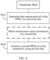
- FIG. 6 is a schematic flowchart of the link error recovery method.
- the link error recovery method includes the following steps.
- a transmitter MLD determines that transmission of a first PPDU on a first link fails.
- a transmitter MLD determines that transmission of a first PPDU on a first link fails may include: when the transmitter MLD does not receive a BA of the first PPDU, the transmitter MLD determines that transmission of the first PPDU fails.
- a transmission failure of the first PPDU may include a transmission failure of some or all content included in the first PPDU.
- the transmitter MLD transmits a second PPDU to a receiver MLD at a first moment by using the first link.
- the receiver MLD receives the second PPDU that is from the transmitter MLD by using the first link.
- the second PPDU is used to retransmit an error part in the first PPDU.
- step S602 may also be: the transmitter MLD retransmits, at the first moment, an error part in the first PPDU to the receiver MLD by using the first link.
- Transmitting the second PPDU by using the first link may also be understood as transmitting the second PPDU on the first link, and the two may be replaced with each other.
- the transmitter MLD transmits a second PPDU to a receiver MLD at a first moment by using the first link may include: when the first link is idle during a first time period, the transmitter MLD transmits the second PPDU to the receiver MLD at the first moment by using the first link.
- An end moment of the first time period is the first moment, and duration of the first time period is PIFS or TBD (To Be Decided) time.
- the transmitter MLD may determine whether the first link is idle during the first time period by performing clear channel assessment (clear channel assessment, CCA).
- clear channel assessment CCA
- duration of the first time period is SIFS.
- the transmitter MLD may use energy detection (energy detection, ED) as a detection manner for determining whether the first link is idle in the SIFS.
- energy detection energy detection, ED
- the transmitter MLD may reduce an ED threshold, for example, reduce the ED threshold from -62 dbm in current 20-MHz channel space to -72 dbm.
- step S602 is performed.
- the transmitter MLD may retransmit an error part in the third PPDU at the first moment. That is, the transmitter MLD synchronously performs error recovery on the first link and the second link. Therefore, PPDUs transmitted on the first link and the second link may be synchronized, thereby avoiding a case in which data is transmitted and received at the same time on a non-STR MLD side.
- an end moment of the second PPDU is the same as that of a fourth PPDU on the second link, and the fourth PPDU is used to retransmit the error part in the third PPDU.
- the receiver MLD may transmit a BA of the second PPDU to the transmitter MLD, or may perform service processing based on the second PPDU. This is not specifically limited in this embodiment of this application.
- the first moment in this embodiment is described in detail below. In different implementations of this embodiment of this application, the first moment may also be different.
- the first moment is a moment at which the transmitter MLD obtains transmission status information of the second link.
- the transmission status information of the second link is used to indicate that transmission of the third PPDU on the second link fails.
- an end moment of the third PPDU is the same as that of the first PPDU.
- the transmitter MLD needs to obtain the transmission status information of the second link.
- the transmission status information of the second link may be obtained by a first station, and the first station is a station that is in the transmitter MLD and supports the first link.
- the first station obtains the transmission status information of the second link may include: the first station receives the transmission status information of the second link that is from a second station, where the second station is a station that is in the transmitter MLD and supports the second link. That is, before step S602, the method may further include: The second station transmits the transmission status information of the second link to the first station. Correspondingly, the first station receives the transmission status information of the second link that is from the second station.
- the moment at which the transmission status information of the second link is obtained is determined as the first moment by the transmitter MLD.
- the first moment is the moment at which the transmitter MLD obtains the transmission status information of the second link.
- the first BA is a BA of the first PPDU
- the first duration is a sum of a length of the first BA and the SIFS.
- the solution may also be described as below:
- the moment at which the transmission status information of the second link is obtained is determined as the first moment by the transmitter MLD.
- the first moment is the moment at which the transmitter MLD obtains the transmission status information of the second link.
- the predicted start moment of the first BA may be a moment at which the transmitter MLD receives the first BA if the first PPDU is normally transmitted, or an interval between the predicted start moment of the first BA and the end moment of the first PPDU is SIFS.
- the predicted end moment of the first BA may be a moment that is at an interval of the length of the first BA from the moment at which the transmitter MLD receives the first BA if the first PPDU is normally transmitted.
- an interval between the predicted end moment of the first BA and the end moment of the first PPDU is a sum of the SIFS and the length of the first BA.
- the predicted start moment of the first BA may be a moment at which the transmitter MLD receives the first BA if the first PPDU is normally transmitted, and a moment at which a transmitter receives the first BA when the first PPDU is normally transmitted is referred to as a start moment of the first BA or an actual start moment of the first BA. Therefore, in this application, the predicted start moment of the first BA may be the same as the actual start moment of the first BA. Therefore, in subsequent embodiments, the predicted start moment of the first BA and the start moment of the first BA may be a same moment. Similarly, the predicted end moment of the first BA and an end moment of the first BA may be a same moment. For a predicted start moment and a predicted end moment of a BA of another PPDU other than the first PPDU in the following embodiments, refer to related descriptions of the first BA.
- the predicted start moment of the first BA is earlier than the moment at which the transmitter MLD obtains the transmission status information of the second link.
- the interval between the predicted start moment of the first BA and the end moment of the first PPDU is SIFS.
- the start moment of the first BA is represented by using t1
- the moment at which the transmitter MLD obtains the transmission status information of the second link is represented by using t2
- the length of the first BA is represented by using L BA .
- Determining the first moment by the transmitter MLD may include: determining t2 as the first moment in a case of t2 - t1 ⁇ L BA + SIFS, or determining t2 as the first moment in a case of t2 - L BA - t1 ⁇ SIFS.
- link recovery may be implemented earlier as compared with the conventional technology in which a failed PPDU is retransmitted at a moment that is at an interval of PIFS after the first BA ends, so that waiting time before the retransmission is reduced. In this case, there may be more time for transmitting new data, thereby increasing link throughput.
- a header of the BA includes a RESTART indication of the BA. Therefore, in this embodiment of this application, the predicted start moment of the first BA may also be referred to as a predicted start moment of the RESTART indication of the first BA, or may be referred to as a moment at which the transmitter MLD is predicted to receive the RESTART of the first BA. This is not specifically limited in this embodiment of this application.
- the transmitter MLD after transmission of the first PPDU fails, the transmitter MLD also obtains transmission status information of the first link.
- the first station transmits the transmission status information of the first link to the second station, where the transmission status information of the first link is used to indicate that transmission of the first PPDU fails.
- the transmitter MLD may obtain the transmission status information of the first link and the transmission status information of the second link at the same time.
- a moment at which the first station receives the transmission status information of the second link is the same as a moment at which the second station receives the transmission status information of the first link.
- the first moment in this implementation may also be understood as a moment at which the transmitter MLD (or the second station) obtains the transmission status information of the first link.
- the transmitter MLD performs a process similar to that of the error recovery of the first link.
- the second station performs a method similar to that of the first station, to perform the error recovery of the second link.
- the first link is the link 1
- the second link is the link 2
- the first PPDU is a PPDU 11
- the third PPDU is a PPDU 21
- the first BA is a BA 11
- a BA of the PPDU 21 is a BA 21
- the AP MLD (or the AP 1) transmits a PPDU 11' at t2 by using the link 1, where the PPDU 11' may be understood as the second PPDU.
- a BA in a dashed box means that the BA is not received, and dashed boxes in the subsequent drawings also indicate that the content in the boxes is not received. This is described herein uniformly, and details are not described in the following embodiments.
- the AP MLD may determine that transmission of the PPDU 21 on the link 2 fails. Subsequently, after obtaining the transmission status information of the link 1 at t2 (that is, the first moment), the AP MLD (or the AP 2) transmits a PPDU 21' at t2 by using the link 2, where the PPDU 21' may be understood as the fourth PPDU.
- the first moment is a moment for transmitting a next PPDU on the first link if the first PPDU is normally transmitted.
- the moment for transmitting a next PPDU on the first link is obtained by adding the end moment of the first PPDU, the length of the first BA, and two SIFSs.
- time for transmitting a next PPDU is represented by using t3
- the end moment of the first PPDU is represented by using t4
- t3 t4 + L BA + 2 SIFS.
- the transmitter MLD determines the moment for transmitting a next PPDU on the first link if the first PPDU is normally transmitted as the first moment.
- the first moment is the moment for transmitting a next PPDU on the first link if the first PPDU is normally transmitted.
- the second moment is the moment for transmitting a next PPDU on the first link if the first PPDU is normally transmitted. Therefore, it may also be considered that if the first PPDU is normally transmitted, when the transmitter MLD does not obtain the transmission status information of the second link before the moment for transmitting a next PPDU on the first link, the first moment is the moment for transmitting a next PPDU on the first link if the first PPDU is normally transmitted.
- that the transmitter MLD does not obtain the transmission status information of the second link may be that the first station does not obtain the transmission status information of the second link.
- a delay in information exchange between the first station and the second station may be excessively large.
- the first station still does not obtain the transmission status information of the second link.
- Determining the first moment by the transmitter MLD may include: when the transmitter MLD does not obtain the transmission status information of the second link at the moment t3, the transmitter MLD determines t3 as the first moment.
- the transmitter MLD performs a process similar to that of the error recovery of the first link.
- the second station performs a method similar to that of the first station, to perform the error recovery of the second link.
- the AP transmitter MLD may determine that transmission of the PPDU 11 on the link 1 fails.
- the AP transmitter MLD (or the AP 1) does not obtain the transmission status information of the second link at the moment t3, the AP transmitter MLD (or the AP 1) transmits a PPDU 11' at t3 by using the link 1, where the PPDU 11' may be understood as the second PPDU.
- the AP transmitter MLD may determine that transmission of the PPDU 21 on the link 2 fails. Subsequently, if the AP transmitter MLD (or the AP 2) does not obtain the transmission status information of the first link at the moment t3, the AP transmitter MLD (or the AP 2) transmits a PPDU 21' at t3 by using the link 2, where the PPDU 21' may be understood as the fourth PPDU.
- an interval between the first moment and the moment at which the transmitter MLD obtains the transmission status information of the second link is PIFS.
- the first moment is later than the moment at which the transmitter MLD obtains the transmission status information of the second link.
- the transmitter MLD transmits the second PPDU to the receiver MLD by using the first link.
- the transmitter MLD determines that an interval between the first moment and the moment at which the transmitter MLD obtains the transmission status information of the second link is PIFS.
- the transmitter MLD determines that the interval between the first moment and the moment at which the transmitter MLD obtains the transmission status information of the second link is PIFS.
- the transmitter MLD performs a process similar to that of the error recovery of the first link.
- the second station performs a method similar to that of the first station, to perform the error recovery of the second link.
- the AP transmitter MLD may determine that transmission of the PPDU 11 on the link 1 fails.
- the AP transmitter MLD uses t2 as a start moment of the first time period, and transmits a PPDU 11' at the end moment of the first time period by using the link 1, where the PPDU 11' may be understood as the second PPDU.
- the AP transmitter MLD may determine that transmission of the PPDU 21 on the link 2 fails. Subsequently, the AP transmitter MLD (or the AP 2) uses t2 as a start moment of the first time period, and transmits a PPDU 21' at the end moment of the first time period by using the link 2, where the PPDU 21' may be understood as the fourth PPDU.
- RTSs/CTSs on the link 1 and the link 2 are completely aligned, which does not limit that the solution in this embodiment is only applicable to a case in which RTSs/CTSs on a plurality of links are completely aligned.
- This solution is also applicable to the case in which RTSs/CTSs on a plurality of links are not completely aligned.
- the solution shown in FIG. 7 may also be applicable to the scenario shown in FIG. 10 , where a PPDU 10 and a PPDU 20 include RTSs, and a BA 10 and a BA 20 include CTSs.
- RTSs on different links are completely aligned, which may indicate that start moments and end moments of RTSs on different links are all the same.
- CTSs on different links are completely aligned, which may indicate that start moments and end moments of CTSs on different links are all the same.
- the transmitter MLD may transmit the second PPDU at the first moment to retransmit the error part in the first PPDU, thereby implementing error recovery of the first link.
- the first moment is the moment at which the transmitter MLD obtains the transmission status information of the second link
- a delay in internal transmission status information exchange of the transmitter MLD is considered. As compared with a case in which transmission status information exchange is assumed to be very fast, product implementation is further facilitated, and design pressure on the transmitter MLD is reduced.
- link recovery can be implemented earlier as compared with a case in which the second PPDU is transmitted at a moment that is at an interval of PIFS from the end moment of the BA of the first PPDU, so that waiting time before the retransmission is reduced. In this case, there may be more time for transmitting new data, thereby increasing link throughput.
- an error recovery method in a scenario in which PPDU transmission failures occur on both the first link and the second link between the transmitter MLD and the receiver MLD is described.
- an embodiment of this application further provides a link error recovery method, and the method does not limit that PPDU transmission failures occur on both a first link and a second link.
- the method may be performed by the transmitter MLD, or by a component (for example, a chip) that may be used in the transmitter MLD.
- description is made by using an example in which the method is performed by the transmitter MLD.
- one of the transmitter MLD and a receiver MLD has an STR capability while the other does not have the STR capability.
- the transmitter MLD is an AP MLD
- the receiver MLD is a non-STR STA MLD
- the AP MLD includes two stations, AP 1 and AP 2, where the AP 1 supports a link 1, and AP 2 supports a link 2
- the non-STR STA MLD includes a STA 1 and a STA 2, where the STA 1 communicates with the AP 1 by using the link 1, and the STA 2 communicates with the AP 2 by using the link 2.
- the method includes the following steps.
- a transmitter MLD determines that transmission of a first PPDU on a first link fails.
- step S1101 For related descriptions in step S1101, refer to step S601, and details are not described herein again.
- the transmitter MLD transmits a second PPDU to a receiver MLD at a first moment by using the first link.
- the receiver MLD receives the second PPDU that is from the transmitter MLD by using the first link.
- the second PPDU is used to retransmit an error part in the first PPDU.
- the second PPDU is used to retransmit an error part in the first PPDU.
- the receiver MLD may transmit a BA of the second PPDU to the transmitter MLD, or may perform service processing based on the second PPDU. This is not specifically limited in this embodiment of this application.
- the first moment in this embodiment is described below.
- the first moment may also be different.
- the first moment is a predicted end moment of a first BA, where the first BA is a BA of the first PPDU.
- An end moment of the third PPDU is the same as that of the first PPDU.
- the first link is the link 1
- the second link is the link 2
- a PPDU transmission failure occurs on the link 1
- no transmission failure occurs on the link 2
- the first PPDU is a PPDU 11
- the first BA is a BA 11.
- an AP transmitter MLD (or the AP 1) may determine that transmission of the PPDU 11 on the link 1 fails.
- the AP MLD (or the AP 1) transmits a PPDU 11' at the predicted end moment of the first BA by using the link 1, where the PPDU 11' is the second PPDU.
- a PPDU 21 is the third PPDU on the link 2
- a PPDU 22 is a fourth PPDU on the link 2.
- the first moment is later than a predicted end moment of a first BA, where the first BA is a BA of the first PPDU.
- An end moment of the third PPDU is the same as that of the first PPDU.
- the first moment for transmitting the PPDU 11' on the first link that is, time for transmitting the PPDU 11' is not earlier than the predicted end moment of the first BA.
- an interval between the first moment and the predicted end moment of the first BA is given duration.
- the interval between the time for transmitting the PPDU 11' on the first link and the predicted end moment of the first BA may be a frame alignment error, for example, may be 8 ⁇ s.
- the first moment is the same as or is aligned with actual end time of the BA 2 on the second link.
- the time for transmitting the PPDU 11' on the first link may be the actual end time of the BA 2 on the second link.
- a BA 21 is a BA of the PPDU 21 on the second link, and a PPDU 21 is the third PPDU on the second link.
- the transmitter MLD has the STR capability, that is, is an STR MLD; and the receiver MLD does not have the STR MLD capability, that is, is a non-STR MLD.
- the first moment is a predicted end moment of a first BA, where the first BA is a BA of the first PPDU.
- An end moment of the third PPDU is the same as that of the first PPDU.
- a BA transmission failure may include a BA decoding failure.
- the link error recovery method provided in this embodiment may further include: the transmitter MLD transmits a fourth PPDU to the receiver MLD at a second moment by using the second link, where the fourth PPDU is used to retransmit a PPDU of an error part in the third PPDU.
- An interval between the second moment and an end moment of the BA of the third PPDU is PIFS, and the second moment is later than the end moment of the BA of the third PPDU.
- an end moment of the fourth PPDU is the same as that of the second PPDU.
- the first link is the link 1
- the second link is the link 2
- a PPDU transmission failure occurs on the link 1
- a BA transmission failure occurs on the link 2
- the first PPDU is a PPDU 11
- the first BA is a BA 11
- the third PPDU is a PPDU 21
- the BA of the third PPDU is a BA 21.
- the AP MLD (or the AP 2) may transmit a PPDU 21' after waiting for duration of PIFS from the end moment of the BA 21, where the PPDU 21' is the fourth PPDU.
- the transmitter MLD has the STR capability, that is, is an STR MLD; and the receiver MLD does not have the STR MLD capability, that is, is a non-STR MLD.
- link recovery may be implemented earlier as compared with a case in which the second PPDU is transmitted at a moment that is at an interval of PIFS from an end moment of the first BA, so that waiting time before retransmission is reduced. In this case, there may be more time for transmitting new data, thereby increasing link throughput.
- an interval between the first moment and a predicted end moment of a first BA is PIFS, and the first moment is later than an end moment of the first BA.
- the link error recovery method provided in this embodiment may further include: the transmitter MLD transmits a fourth PPDU to the receiver MLD at a second moment by using the second link, where the fourth PPDU is used to retransmit a PPDU of an error part in the third PPDU.
- the transmitter MLD transmits a fourth PPDU to the receiver MLD at a second moment by using the second link, where the fourth PPDU is used to retransmit a PPDU of an error part in the third PPDU.
- the first link is the link 1
- the second link is the link 2
- a PPDU transmission failure occurs on the link 1
- a BA transmission failure occurs on the link 2
- the first PPDU is a PPDU 11
- the first BA is a BA 11
- the third PPDU is a PPDU 21
- the BA of the third PPDU is a BA 21.
- the AP MLD transmits a PPDU 1 1' at the first moment, where the PPDU 1 1' is the second PPDU.
- the AP MLD or the AP 2 transmits a PPDU 21' at the second moment, where the PPDU 21' is the fourth PPDU.
- the transmitter MLD does not have the STR capability, that is, is a non-STR MLD; and the receiver MLD has the STR MLD capability, that is, is an STR MLD.
- the first moment may be a moment at which the transmitter MLD obtains transmission status information of the second link, where the transmission status information of the second link may be used to indicate that transmission of the BA of the third PPDU fails.
- the first moment is earlier than a predicted end moment of a first BA.
- the link error recovery method provided in this embodiment may further include: the transmitter MLD transmits a fourth PPDU to the receiver MLD at a second moment by using the second link, where the fourth PPDU is used to retransmit a PPDU of an error part in the third PPDU.
- the transmitter MLD transmits a fourth PPDU to the receiver MLD at a second moment by using the second link, where the fourth PPDU is used to retransmit a PPDU of an error part in the third PPDU.
- the first link is the link 1
- the second link is the link 2
- a PPDU transmission failure occurs on the link 1
- a BA transmission failure occurs on the link 2
- the first PPDU is a PPDU 11
- the first BA is a BA 11
- the third PPDU is a PPDU 21
- the BA of the third PPDU is a BA 21
- the moment at which the transmitter MLD obtains the transmission status information of the second link is t2.
- the AP MLD transmits a PPDU 11' at t2, where the PPDU 11' is the second PPDU.
- the AP MLD transmits a PPDU 21' at a moment that is at an interval of PIFS from the BA 21, where the PPDU 21' is the fourth PPDU.
- the transmitter MLD has the STR capability, that is, is an STR MLD; and the receiver MLD does not have the STR MLD capability, that is, is a non-STR MLD.
- link recovery may be implemented earlier as compared with a case in which the second PPDU is transmitted at a moment that is at an interval of PIFS from the end moment of the first BA, so that waiting time before retransmission is reduced. In this case, there may be more time for transmitting new data, thereby increasing link throughput.
- the end moment of the second PPDU is the same as that of the fourth PPDU on the second link.
- the PPDU that is transmitted later may adjust the PPDU length thereof based on the length of the PPDU that is transmitted earlier. For example, the length is adjusted by aggregating fewer media access control protocol data units (media access control protocol data units, MPDUs) or by reducing padding (padding).
- media access control protocol data units media access control protocol data units, MPDUs
- MPDUs media access control protocol data units
- channel backoff may be started at the predicted end moment of the first BA. After the channel backoff ends, the transmitter MLD transmits the second PPDU to the receiver MLD by using the first link. Based on this solution, backoff recovery may be continued when PIFS recovery fails, thereby improving reliability of link error recovery.
- the transmitter MLD may transmit the second PPDU at the first moment, to retransmit the error part in the first PPDU, thereby implementing error recovery of the first link.
- the fourth PPDU may be transmitted at the second moment, to retransmit the error part in the third PPDU, thereby implementing error recovery of the second link.
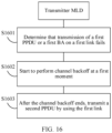
- the method includes the following steps.
- a transmitter MLD determines that transmission of a first PPDU or a first BA on a first link fails.
- the first BA is a BA of the first PPDU.
- the transmitter MLD starts to perform channel backoff at a first moment.
- the first moment is an end moment of the first BA. It may be understood that the channel backoff is channel backoff on the first link.
- the transmitter MLD transmits a second PPDU to a receiver MLD by using the first link.
- the receiver MLD receives the second PPDU that is from the transmitter MLD by using the first link.
- the second PPDU is used to retransmit an error part in the first PPDU.
- step S1603 the transmitter MLD does not perform CCA before transmitting the second PPDU.
- the first link is the link 1
- the second link is the link 2
- a PPDU transmission failure occurs on the link 1
- no transmission failure occurs on the link 2
- the first PPDU is a PPDU 11
- the first BA is a BA 11.
- the AP MLD or the AP 1 starts to perform channel backoff, and transmits a PPDU 11' after the backoff ends, where the PPDU 11' is the second PPDU.
- the transmitter MLD may also perform channel backoff on the second link at an end moment of the BA; and after the channel backoff ends, transmit a fourth PPDU to the receiver MLD on the second link, to retransmit an error part in the third PPDU.
- the receiver MLD may transmit a BA of the second PPDU to the transmitter MLD, or may perform service processing based on the second PPDU. This is not specifically limited in this embodiment of this application.
- the transmitter MLD may start to perform channel backoff at the predicted end moment of the BA of the first PPDU, and transmit the second PPDU on the first link after the channel backoff ends, to retransmit the error part in the first PPDU, thereby implementing error recovery of the first link.
- channel backoff on the second link may be started at an end moment of the BA, and the fourth PPDU is transmitted after the channel backoff ends, to retransmit the error part in the third PPDU, thereby implementing error recovery of the second link.
- an embodiment of this application further provides a link error recovery method.
- the method may be performed by a transmitter MLD, or by a component (for example, a chip) that may be used in the transmitter MLD.
- description is made by using an example in which the method is performed by the transmitter MLD.
- one of the transmitter MLD and a receiver MLD has an STR capability while the other does not have the STR capability.
- one of the transmitter MLD and the receiver MLD is an STR MLD, and the other is a non-STR MLD.
- interframe space after a BA in the TXOP is PIFS
- interframe space after a PPDU is still SIFS.
- interframe space after a BA 11 and a BA 12 is SIFS
- interframe space after a PPDU 11 and a PPDU 12 is PIFS.
- the BA in this application is a type of response frame. Therefore, the interframe space after the BA in the TXOP is PIFS, which may be understood as that the interframe space after the response frame is PIFS.
- receiving the BA may also be understood as receiving the response frame.
- FIG. 19 is a schematic flowchart of the method.
- the link error recovery method may include the following steps. S1901. A transmitter MLD receives a first BA on a first link.
- the first BA is a BA of a first PPDU.
- decoding fails after the BA of the first PPDU is received by the transmitter MLD, it may be considered as that transmission of the BA of the first PPDU fails.
- the transmitter MLD transmits a second PPDU to a receiver MLD by using the first link.
- the receiver MLD receives the second PPDU that is from the transmitter MLD by using the first link.
- An interval between a start moment of the second PPDU and an end moment of the first BA is interframe space, and the interframe space is a PIFS.
- the second PPDU is used to retransmit an error part in the first PPDU.
- the first link is a link 1
- a second link is a link 2
- the first PPDU on the link 1 is a PPDU 12
- decoding of a BA (BA 12) of the PPDU 12 fails.
- the transmitter MLD transmits a PPDU 12' in a next frame of the BA 12. Interframe space between the BA 12 and the PPDU 12' is PIFS, and the PPDU 12' is the second PPDU.
- the transmitter MLD may still transmit the second PPDU to a receiver in a next frame of the first BA by using the first link, to retransmit the error part in the first PPDU.
- the first link is a link 1
- a second link is a link 2
- the first PPDU on the link 1 is a PPDU 12
- transmission of the PPDU 12 fails.
- the transmitter MLD transmits a PPDU 12' in a next frame of the BA 12. Interframe space between the BA 12 and the PPDU 12' is PIFS, and the PPDU 12' is the second PPDU.
- the receiver MLD may transmit a BA of the second PPDU to the transmitter MLD, or may perform service processing based on the second PPDU. This is not specifically limited in this embodiment of this application.
- links between the transmitter MLD and the receiver MLD include a link 1 and a link 2.
- the link 1 and the link 2 are merely examples for distinguishing between the links, and link statuses of the link 1 and the link 2 may be interchanged. When the link statuses are interchanged, the same method may still be used to perform error recovery on the error link.
- Table 2 Scenario Status of link 1 Status of link 2 Transmission scheme (or error recovery scheme) Remarks Case 1 Success Success Interframe space after a BA is SIFS.
- Case 2 PPDU error Success Link 1 Time for transmitting a next PPDU is not earlier than an end time of a BA on the link 2. See the scheme shown in FIG. 12 of this application.
- Link 2 Normal transmission. Interframe space after a BA is SIFS.
- Case 3 Success BA error Link 1 Normal transmission. Interframe space after a BA is SIFS. See IEEE 802.11-20/0427r1 Synchronous multi-link operation (NXP).
- Link 2 PIFS or TBD recovery is started at end time of an error BA, and start time of a next PPDU is not aligned with start time of a PPDU on the link 1.
- Case 4 PPDU error PPDU error PPDU error
- Link 1 A next PPDU is transmitted when transmission status information of the other link is obtained or at a moment that is at an interval of SIFS from a predicted end moment of a BA. See the schemes shown in FIG. 6 to FIG. 9 of this application.
- Link 2 Same as the link 1.
- Case 5 PPDU error BA error Link 1: A next PPDU is transmitted at a predicted end moment of a BA or at a moment when transmission status information of the link 2 is obtained. See the schemes shown in FIG. 13 or FIG. 15 of this application.
- Link 2 A next PPDU is transmitted at a moment that is at an interval of PIFS from an end moment of a BA.
- Link 1 Normal transmission. Interframe space after a BA is SIFS. See IEEE 802.11-20/0427r1 Synchronous multi-link operation (NXP).
- Link 2 A next PPDU is transmitted at a moment that is at an interval of SIFS from an end moment of a BA on the link 1.
- Case 3 PPDU error PPDU error
- Link 1 A next PPDU is transmitted when transmission status information of the other link is obtained or at a moment that is at an interval of SIFS from a predicted end moment of a BA. See the schemes shown in FIG. 6 to FIG. 9 of this application.
- Link 2 Same as the link 1.
- Case 4 PPDU error BA error
- Link 1 A next PPDU is transmitted at a moment that is at an interval of PIFS from a predicted end moment of a BA. See the scheme shown in FIG. 14 of this application.
- Link 2 A next PPDU is transmitted at a moment that is at an interval of PIFS from an end moment of a BA.
- the methods and/or steps implemented by the transmitter MLD may also be implemented by a component (for example, a chip or a circuit) that may be used in the transmitter MLD.
- an embodiment of this application further provides a communication apparatus, and the communication apparatus is configured to implement the foregoing methods.
- the communication apparatus may be the transmitter MLD in the foregoing method embodiments, or may be an apparatus including the transmitter MLD, or may be an apparatus, for example, a system chip, included in the transmitter MLD.
- the communication apparatus includes corresponding hardware structures and/or software modules for performing the functions.
- a person skilled in the art should be easily aware that units and algorithm steps in the examples described with reference to the embodiments disclosed in this specification can be implemented in a form of hardware or a combination of hardware and computer software in this application. Whether a function is implemented by hardware or hardware driven by computer software depends on particular applications and design constraints of the technical solutions. A person skilled in the art may use different methods to implement the described functions for each particular application, but it should not be considered that the implementation goes beyond the scope of this application.
- the communication apparatus may be divided into functional modules based on the foregoing method embodiments.
- each functional module may be obtained through division based on each corresponding function, or two or more functions may be integrated into one processing module.
- the integrated module may be implemented in a form of hardware, or may be implemented in a form of a software functional module. It should be noted that division into the modules is an example and is merely logical function division in the embodiments of this application. In actual implementation, another division manner may be used.
- FIG. 22 is a schematic diagram of a structure of a transmitter MLD 220.
- the transmitter MLD 220 includes a transceiver module 2201 and a processing module 2202.
- the transceiver module 2201 may also be referred to as a transceiver unit, is configured to implement a transmitting and/or receiving function.
- the transceiver module 2201 may be a transceiver circuit, a transceiver, a transceiver, or a communication interface.
- the processing module 2202 is configured to determine that transmission of a first physical protocol data unit PPDU on a first link fails.
- the transceiver module 2201 is configured to transmit a second PPDU to a receiver MLD at a first moment by using the first link, the second PPDU being used to retransmit an error part in the first PPDU.
- the first moment is a moment at which the transmitter MLD obtains transmission status information of a second link, and the transmission status information of the second link is used to indicate that transmission of a third PPDU on the second link fails.
- the first moment is a moment for transmitting a next PPDU on the first link if the first PPDU is normally transmitted.
- the processing module 2202 is configured to determine that transmission of a first physical protocol data unit PPDU on a first link fails.
- the transceiver module 2201 is configured to transmit a second PPDU to a receiver MLD at a first moment by using the first link, the second PPDU being used to retransmit an error part in the first PPDU.
- the first moment is a predicted end moment of a first acknowledgement block BA
- the first BA is a BA of the first PPDU.
- the processing module 2202 is configured to determine that transmission of a first physical protocol data unit PPDU or a first acknowledgement block BA on a first link fails, where the first BA is a BA of the first PPDU.
- the processing module 2202 is further configured to start to perform channel backoff at a first moment, where the first moment is an end moment of the first BA.
- the transceiver module 2201 is configured to transmit, after the channel backoff ends, a second PPDU to a receiver MLD by using the first link, the second PPDU being used to retransmit an error part in the first PPDU.
- the processing module 2202 is configured to receive a first block acknowledgement BA on a first link by using the transceiver module 2201, where the first BA is a BA of a first physical protocol data unit PPDU.
- the processing module 2202 is further configured to transmit a second PPDU to a receiver MLD on the first link by using the transceiver module 2201, where an interval between a start moment of the second PPDU and an end moment of the first BA is interframe space, and the interframe space is point coordination function interframe space PIFS.
- the transmitter MLD 220 is presented in a form of division into functional modules in an integrated manner.
- the "module” herein may be a specified ASIC, a circuit, a processor and a memory that execute one or more software or firmware programs, an integrated logic circuit, and/or another component that can provide the foregoing functions.
- the transmitter MLD 220 provided in this embodiment may perform the foregoing communication methods, for technical effects that can be obtained by the transmitter MLD 220, refer to the foregoing method embodiments. Details are not described herein again.
- FIG. 23 is a schematic diagram of a hardware structure of a communication device 230 according to an embodiment of this application.
- the communication device 230 includes at least one processor 2301, a communication line 2302, a memory 2303, and at least one communication interface 2304.
- the functions of the foregoing transmitter MLD may be implemented by using the communication device 230.
- the processor 2301 in FIG. 23 may invoke computer-executable instructions stored in the memory 2303, so that the communication device 230 performs the methods in the foregoing method embodiments.
- the steps/the implementation process in FIG. 6 , FIG. 11 , FIG. 16 , or FIG. 19 may be implemented by the processor 2301 in FIG. 23 by invoking the computer-executable instructions stored in the memory 2303.
- the processing-related functions/the implementation process in FIG. 6 , FIG. 11 , FIG. 16 , or FIG. 19 may be implemented by the processor 2301 in FIG. 23 by invoking the computer-executable instructions stored in the memory 2303.
- the transmitting and receiving-related functions/the implementation process in FIG. 6 , FIG. 11 , FIG. 16 , or FIG. 19 may be implemented by using the communication interface 2304 in FIG. 23 .
- the processor 2301 may be a general-purpose central processing unit (central processing unit, CPU), a microprocessor, an application-specific integrated circuit (application-specific integrated circuit, ASIC), or one or more integrated circuits configured to control execution of a program in the solutions of this application.
- CPU central processing unit
- ASIC application-specific integrated circuit
- the communication line 2302 may include a path on which information is transferred between the foregoing components.
- the communication interface 2304 is any apparatus such as a transceiver, and is configured to communicate with another device or a communication network such as the Ethernet, a radio access network (radio access network, RAN), or a wireless local area network (wireless local area network, WLAN).
- a radio access network radio access network, RAN
- a wireless local area network wireless local area network, WLAN
- the memory 2303 may be a read-only memory (read-only memory, ROM) or another type of static storage device that can store static information and instructions, a random access memory (random access memory, RAM) or another type of dynamic storage device that can store information and instructions, an electrically erasable programmable read only memory (electrically erasable programmable read-only memory, EEPROM), a compact disc read-only memory (compact disc read-only memory, CD-ROM) or another optical disc storage, an optical disk storage (including a compact optical disc, a laser disc, an optical disc, digital a versatile optical disc, a Blu-ray disc, and the like), a magnetic disk storage medium or another magnetic storage device, or any other medium capable of carrying or storing desired program code in a form of an instruction or a data structure and capable of being accessed by a computer, but not limited thereto.
- the memory may exist independently, and is connected to the processor through the communication line 2302. The memory may alternatively be integrated with the processor.
- the memory 2303 is configured to store computer-executable instructions for executing the solutions of this application, and execution is controlled by the processor 2301.
- the processor 2301 is configured to execute the computer-executable instruction stored in the memory 2303, to implement the link error recovery methods provided in the following embodiments of this application.
- the computer-executable instructions in this embodiment of this application may also be referred to as application program code. This is not specifically limited in this embodiment of this application.
- the processor 2301 may include one or more CPUs, for example, a CPU 0 and a CPU 1 in FIG. 23 .
- the communication device 230 may include a plurality of processors, such as the processor 2301 and a processor 2308 in FIG. 23 .
- Each of the processors may be a single-core (single-CPU) processor or a multi-core (multi-CPU) processor.
- the processor herein may be one or more devices, circuits, and/or processing cores configured to process data (for example, computer program instructions).
- the communication device 230 may further include an output device 2305 and an input device 2306.
- the output device 2305 communicates with the processor 2301, and may display information in a plurality of manners.
- the output device 2305 may be a liquid crystal display (liquid crystal display, LCD), a light emitting diode (light emitting diode, LED) display device, a cathode ray tube (cathode ray tube, CRT) display device, a projector (projector), or the like.
- the input device 2306 communicates with the processor 2301, and may receive user input in a plurality of manners.
- the input device 2306 may be a mouse, a keyboard, a touchscreen device, or a sensing device.
- the foregoing communication device 230 may be a general-purpose device or a dedicated device.
- the communication device 230 may be a desktop computer, a portable computer, a network server, a personal digital assistant (personal digital assistant, PDA), a mobile phone, a tablet computer, a wireless terminal device, an embedded device, or a device having a structure similar to that in FIG. 23 .
- PDA personal digital assistant
- a type of the communication device 230 is not limited in this embodiment of this application.
- an embodiment of this application further provides a communication apparatus (for example, the communication apparatus may be a chip or a chip system), where the communication apparatus includes a processor, configured to implement the method in any one of the foregoing method embodiments.
- the communication apparatus further includes a memory.
- the memory is configured to store necessary program instructions and data.
- the processor may invoke program code stored in the memory, to indicate the communication apparatus to implement the method in any one of the foregoing method embodiments.
- the memory may not be located in the communication apparatus.
- the communication apparatus is a chip system
- the chip system may include a chip, or include a chip and other discrete devices. This is not specifically limited in this embodiment of this application.
- All or some of the foregoing embodiments may be implemented through software, hardware, firmware, or any combination thereof.
- a software program is used to implement the embodiments, all or some of the embodiments may be implemented in a form of a computer program product.
- the computer program product includes one or more computer instructions. When the computer program instructions are loaded and executed on a computer, all or some of the procedures or functions in the embodiments of this application are generated.
- the computer may be a general-purpose computer, a dedicated computer, a computer network, or another programmable apparatus.
- the computer instructions may be stored in a computer-readable storage medium or may be transmitted from a computer-readable storage medium to another computer-readable storage medium.
- the computer instructions may be transmitted from a website, computer, server, or data center to another website, computer, server, or data center in a wired (for example, a coaxial cable, an optical fiber, or a digital subscriber line (digital subscriber line, DSL)) or wireless (for example, infrared, radio, or microwave) manner.
- the computer-readable storage medium may be any usable medium accessible by the computer, or a data storage device, such as a server or a data center, integrating one or more usable media.
- the usable medium may be a magnetic medium (for example, a floppy disk, a hard disk, or a magnetic tape), an optical medium (for example, a DVD), a semiconductor medium (for example, a solid-state drive (solid state disk, SSD)), or the like.
- the computer may include the foregoing apparatus.
Landscapes
- Engineering & Computer Science (AREA)
- Computer Networks & Wireless Communication (AREA)
- Signal Processing (AREA)
- Mobile Radio Communication Systems (AREA)
- Detection And Prevention Of Errors In Transmission (AREA)
- Vehicle Body Suspensions (AREA)
- Cable Transmission Systems, Equalization Of Radio And Reduction Of Echo (AREA)
- Communication Control (AREA)
Applications Claiming Priority (3)
| Application Number | Priority Date | Filing Date | Title |
|---|---|---|---|
| CN202010664563 | 2020-07-10 | ||
| CN202010781257.0A CN113923798A (zh) | 2020-07-10 | 2020-08-06 | 链路的错误恢复方法及装置 |
| PCT/CN2021/104394 WO2022007728A1 (zh) | 2020-07-10 | 2021-07-03 | 链路的错误恢复方法及装置 |
Publications (2)
| Publication Number | Publication Date |
|---|---|
| EP4170948A1 true EP4170948A1 (de) | 2023-04-26 |
| EP4170948A4 EP4170948A4 (de) | 2023-12-27 |
Family
ID=79232470
Family Applications (1)
| Application Number | Title | Priority Date | Filing Date |
|---|---|---|---|
| EP21836884.3A Pending EP4170948A4 (de) | 2020-07-10 | 2021-07-03 | Verfahren und vorrichtung zur wiederherstellung von verbindungsfehlern |
Country Status (10)
| Country | Link |
|---|---|
| US (1) | US12604355B2 (de) |
| EP (1) | EP4170948A4 (de) |
| JP (1) | JP7485847B2 (de) |
| KR (1) | KR20230025918A (de) |
| CN (1) | CN113923798A (de) |
| AU (1) | AU2021305753B2 (de) |
| BR (1) | BR112023000358A2 (de) |
| CA (1) | CA3185569A1 (de) |
| MX (1) | MX2023000506A (de) |
| WO (1) | WO2022007728A1 (de) |
Families Citing this family (5)
| Publication number | Priority date | Publication date | Assignee | Title |
|---|---|---|---|---|
| KR20230005824A (ko) | 2020-05-04 | 2023-01-10 | 주식회사 윌러스표준기술연구소 | 멀티 링크를 사용하는 무선 통신 방법 및 이를 사용하는 무선 통신 단말 |
| CN114205067B (zh) * | 2020-08-29 | 2023-09-08 | 华为技术有限公司 | 多链路同步发送方法及装置 |
| JP7635057B2 (ja) * | 2021-04-07 | 2025-02-25 | キヤノン株式会社 | 通信装置、通信装置の制御方法、およびプログラム |
| US20220338253A1 (en) * | 2021-04-15 | 2022-10-20 | Mediatek Singapore Pte. Ltd. | Systems and methods of enhanced multi-link operation responsive to transmission failure |
| WO2024054005A1 (ko) * | 2022-09-08 | 2024-03-14 | 현대자동차주식회사 | 무선랜에서 오류 복구의 방법 및 장치 |
Family Cites Families (14)
| Publication number | Priority date | Publication date | Assignee | Title |
|---|---|---|---|---|
| US9173191B2 (en) * | 2009-12-20 | 2015-10-27 | Intel Corporation | Device, system and method of simultaneously communicating with a group of wireless communication devices |
| WO2015034166A1 (ko) * | 2013-09-06 | 2015-03-12 | 엘지전자 주식회사 | 무선 통신 시스템에서 데이터 단위의 복구 방법 및 장치 |
| US9264209B2 (en) * | 2014-01-07 | 2016-02-16 | Google Inc. | Method and control circuitry for performing full-duplex wireless communication |
| CN109804611B (zh) * | 2016-10-21 | 2022-03-01 | 松下电器(美国)知识产权公司 | 使用聚合物理层收敛协议数据单元的通信装置和通信方法 |
| CN108012313B (zh) * | 2016-10-31 | 2020-12-15 | 华为技术有限公司 | 帧传输方法、设备及系统 |
| US10856203B2 (en) * | 2017-01-19 | 2020-12-01 | Qualcomm Incorporated | Signaling for link aggregation setup and reconfiguration |
| CN108631961A (zh) * | 2017-03-24 | 2018-10-09 | 中国移动通信有限公司研究院 | 一种多连接下实现多链路重传的方法及基站 |
| CN108631954B (zh) * | 2017-03-24 | 2020-12-11 | 电信科学技术研究院 | 一种数据传输方法及装置 |
| WO2019182421A1 (ko) * | 2018-03-23 | 2019-09-26 | 엘지전자 주식회사 | 무선랜 시스템에서 제 harq 프로세스를 지원하기 위한 방법 및 이를 이용한 무선 단말 |
| US11076385B2 (en) * | 2018-08-10 | 2021-07-27 | Intel Corporation | Block acknowledgement and fragmentation in multi-link communication between multi-link logical entities |
| CN110572244B (zh) * | 2019-09-06 | 2020-11-06 | 展讯通信(上海)有限公司 | 数据重传、数据接收响应方法及装置、存储介质 |
| US12021950B2 (en) * | 2019-11-26 | 2024-06-25 | Nxp Usa, Inc. | Multi-link communications |
| US12598643B2 (en) * | 2020-04-09 | 2026-04-07 | Lg Electronics Inc. | Multi-link error recovery |
| US20230319884A1 (en) * | 2020-06-30 | 2023-10-05 | Wilus Institute Of Standards And Technology Inc. | Wireless communication method using multiple links, and wireless communication terminal using same |
-
2020
- 2020-08-06 CN CN202010781257.0A patent/CN113923798A/zh active Pending
-
2021
- 2021-07-03 WO PCT/CN2021/104394 patent/WO2022007728A1/zh not_active Ceased
- 2021-07-03 CA CA3185569A patent/CA3185569A1/en active Pending
- 2021-07-03 BR BR112023000358A patent/BR112023000358A2/pt unknown
- 2021-07-03 KR KR1020237003027A patent/KR20230025918A/ko active Pending
- 2021-07-03 MX MX2023000506A patent/MX2023000506A/es unknown
- 2021-07-03 EP EP21836884.3A patent/EP4170948A4/de active Pending
- 2021-07-03 JP JP2023500426A patent/JP7485847B2/ja active Active
- 2021-07-03 AU AU2021305753A patent/AU2021305753B2/en active Active
-
2023
- 2023-01-03 US US18/149,490 patent/US12604355B2/en active Active
Also Published As
| Publication number | Publication date |
|---|---|
| AU2021305753B2 (en) | 2024-08-01 |
| JP7485847B2 (ja) | 2024-05-16 |
| WO2022007728A9 (zh) | 2023-02-09 |
| WO2022007728A1 (zh) | 2022-01-13 |
| KR20230025918A (ko) | 2023-02-23 |
| JP2023533004A (ja) | 2023-08-01 |
| AU2021305753A1 (en) | 2023-02-09 |
| CN113923798A (zh) | 2022-01-11 |
| BR112023000358A2 (pt) | 2023-03-21 |
| EP4170948A4 (de) | 2023-12-27 |
| US12604355B2 (en) | 2026-04-14 |
| US20230145901A1 (en) | 2023-05-11 |
| MX2023000506A (es) | 2023-02-09 |
| CA3185569A1 (en) | 2022-01-13 |
Similar Documents
| Publication | Publication Date | Title |
|---|---|---|
| US10736145B2 (en) | Method and device for performing uplink transmission after receiving trigger frame in wireless LAN system | |
| US12604355B2 (en) | Link error recovery method and apparatus | |
| US9918342B2 (en) | Method and device for transmitting/receiving frame in accordance with bandwidth thereof in WLAN system | |
| RU2639296C1 (ru) | Способ и устройство для приема и передачи кадра, содержащего идентификатор частичной ассоциации в системе беспроводной локальной сети (lan) | |
| US9585165B2 (en) | Method and apparatus for accessing channel using null data packet in wireless LAN system | |
| US12058731B2 (en) | Communication method and apparatus | |
| US20150244448A1 (en) | Method and apparatus for performing relay operation in wireless lan system | |
| US20150124784A1 (en) | Channel access method in wireless communication system and apparatus for same | |
| US20230217494A1 (en) | Multi-link synchronous transmission method and apparatus | |
| JP2025026915A (ja) | チャネルリスニング方法および関連装置 | |
| US20180279362A1 (en) | Method ad device for transmitting and receiving frame related to multi-user transmission in wireless lan system | |
| US20260005792A1 (en) | Communication method and communication apparatus | |
| WO2025213390A1 (zh) | 无线通信方法以及通信设备 | |
| CN118540013A (zh) | 通信方法及装置、计算机可读存储介质 |
Legal Events
| Date | Code | Title | Description |
|---|---|---|---|
| STAA | Information on the status of an ep patent application or granted ep patent |
Free format text: STATUS: THE INTERNATIONAL PUBLICATION HAS BEEN MADE |
|
| PUAI | Public reference made under article 153(3) epc to a published international application that has entered the european phase |
Free format text: ORIGINAL CODE: 0009012 |
|
| STAA | Information on the status of an ep patent application or granted ep patent |
Free format text: STATUS: REQUEST FOR EXAMINATION WAS MADE |
|
| 17P | Request for examination filed |
Effective date: 20230118 |
|
| AK | Designated contracting states |
Kind code of ref document: A1 Designated state(s): AL AT BE BG CH CY CZ DE DK EE ES FI FR GB GR HR HU IE IS IT LI LT LU LV MC MK MT NL NO PL PT RO RS SE SI SK SM TR |
|
| DAV | Request for validation of the european patent (deleted) | ||
| DAX | Request for extension of the european patent (deleted) | ||
| A4 | Supplementary search report drawn up and despatched |
Effective date: 20231128 |
|
| RIC1 | Information provided on ipc code assigned before grant |
Ipc: H04L 1/18 20230101AFI20231122BHEP |
|
| STAA | Information on the status of an ep patent application or granted ep patent |
Free format text: STATUS: EXAMINATION IS IN PROGRESS |
|
| 17Q | First examination report despatched |
Effective date: 20250422 |
|
| GRAP | Despatch of communication of intention to grant a patent |
Free format text: ORIGINAL CODE: EPIDOSNIGR1 |
|
| STAA | Information on the status of an ep patent application or granted ep patent |
Free format text: STATUS: GRANT OF PATENT IS INTENDED |
|
| INTG | Intention to grant announced |
Effective date: 20251203 |
|
| RAP1 | Party data changed (applicant data changed or rights of an application transferred) |
Owner name: NOKIA TECHNOLOGIES OY |
|
| GRAJ | Information related to disapproval of communication of intention to grant by the applicant or resumption of examination proceedings by the epo deleted |
Free format text: ORIGINAL CODE: EPIDOSDIGR1 |
|
| STAA | Information on the status of an ep patent application or granted ep patent |
Free format text: STATUS: EXAMINATION IS IN PROGRESS |
|
| INTC | Intention to grant announced (deleted) |