EP4170980A1 - Procédé de communication et appareil associé - Google Patents
Procédé de communication et appareil associé Download PDFInfo
- Publication number
- EP4170980A1 EP4170980A1 EP20943639.3A EP20943639A EP4170980A1 EP 4170980 A1 EP4170980 A1 EP 4170980A1 EP 20943639 A EP20943639 A EP 20943639A EP 4170980 A1 EP4170980 A1 EP 4170980A1
- Authority
- EP
- European Patent Office
- Prior art keywords
- node
- moment
- target cell
- target
- sending
- Prior art date
- Legal status (The legal status is an assumption and is not a legal conclusion. Google has not performed a legal analysis and makes no representation as to the accuracy of the status listed.)
- Granted
Links
Images



Classifications
-
- H—ELECTRICITY
- H04—ELECTRIC COMMUNICATION TECHNIQUE
- H04L—TRANSMISSION OF DIGITAL INFORMATION, e.g. TELEGRAPHIC COMMUNICATION
- H04L47/00—Traffic control in data switching networks
- H04L47/10—Flow control; Congestion control
- H04L47/28—Flow control; Congestion control in relation to timing considerations
- H04L47/283—Flow control; Congestion control in relation to timing considerations in response to processing delays, e.g. caused by jitter or round trip time [RTT]
-
- H—ELECTRICITY
- H04—ELECTRIC COMMUNICATION TECHNIQUE
- H04L—TRANSMISSION OF DIGITAL INFORMATION, e.g. TELEGRAPHIC COMMUNICATION
- H04L12/00—Data switching networks
- H04L12/28—Data switching networks characterised by path configuration, e.g. LAN [Local Area Networks] or WAN [Wide Area Networks]
- H04L12/40—Bus networks
- H04L12/40006—Architecture of a communication node
- H04L12/40013—Details regarding a bus controller
-
- H—ELECTRICITY
- H04—ELECTRIC COMMUNICATION TECHNIQUE
- H04L—TRANSMISSION OF DIGITAL INFORMATION, e.g. TELEGRAPHIC COMMUNICATION
- H04L47/00—Traffic control in data switching networks
- H04L47/10—Flow control; Congestion control
- H04L47/12—Avoiding congestion; Recovering from congestion
- H04L47/125—Avoiding congestion; Recovering from congestion by balancing the load, e.g. traffic engineering
-
- H—ELECTRICITY
- H04—ELECTRIC COMMUNICATION TECHNIQUE
- H04L—TRANSMISSION OF DIGITAL INFORMATION, e.g. TELEGRAPHIC COMMUNICATION
- H04L47/00—Traffic control in data switching networks
- H04L47/10—Flow control; Congestion control
- H04L47/17—Interaction among intermediate nodes, e.g. hop by hop
Definitions
- This application relates to the communication field, and in particular, to a communication method and a related device.
- a line card chassis (Line Card Chassis, LCC) is usually formed by at least one line card (Line Card, LC) and at least one fabric card (Fabric Card, FC).
- LCC Line Card Chassis
- each LC includes at least one fabric interface chip (Fabric Interface chip, FIC)
- each FC includes at least one switch element (Switch Element, SE).
- a plurality of FICs in the switching network system may be interconnected to a plurality of SEs to communicate with each other.
- a single-level single-chassis networking scenario is used as an example.
- Ingress FIC Ingress FIC
- SE 102 At least one SE 102
- Egress FIC egress FIC
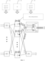
- FIG. 1 At least one ingress FIC (Ingress FIC) 101, at least one SE 102, and at least one egress FIC (Egress FIC) 103 are included. After a packet is split on a side of the ingress FIC 101 to obtain cells, the cells are distributed to a plurality of SEs 102, and then are output by the plurality of SEs 102 to the egress FIC 103.
- the egress FIC In a communication process in which the plurality of SEs 102 output the cells to the egress FIC 103, because instantaneous congestion degrees of output queues (Output Queue, OQ) of the SEs are different, delays for the cells to arrive at the egress FIC through different SEs are also different. In this case, the egress FIC needs to reserve an input queue (Input Queue, IQ) buffer (Buffer) to eliminate a delay difference of the paths, to finally complete sorting and packet assembly. Then, the egress FIC sends out the cells. In the current switching network system, IQ resources used by the egress FIC for sorting are limited.
- the egress FIC can only passively back-pressure a corresponding SE.
- Embodiments of this application provide a communication method and a related device, so that an upper-level node in a switching network system shares sorting load of a lower-level node, to avoid an increased transmission delay caused by back pressure of the lower-level node, optimize sorting resources between different levels of nodes in the switching network system, and improve stability of the switching network system.
- a first aspect of the embodiments of this application provides a communication method, applied to a first node in a switching network system.
- the first node in the switching network system obtains a to-be-sent target cell and a target moment, where the target moment is used to indicate a moment at which the target cell is processed.
- the first node determines a sending delay threshold of the target cell.
- the first node obtains a current system moment in the first node.
- the first node sends the target cell to a lower-level node when a difference between the system moment and the target moment is greater than the sending delay threshold.
- the first node obtains the target cell and the target moment.
- the first node sends the target cell to the lower-level node in the switching network system
- the first node sends the target cell to the lower-level node only when the difference between the system moment and the target moment is greater than the sending delay threshold.
- the first node delays, by using the sending delay threshold, sending the target cell, so that an upper-level node in the switching network system shares sorting load of a lower-level node, to avoid an increased transmission delay caused by back pressure of the lower-level node, optimize sorting resources between different levels of nodes in the switching network system, and improve stability of the switching network system.
- a process in which the first node determines the sending delay threshold of the target cell may include: The first node obtains a quantity of hops between the first node and the initial node in the switching network system. Thereafter, the first node determines the sending delay threshold based on the quantity of hops, where a size of the quantity of hops is positively correlated with a size of the sending delay threshold.
- the first node is not the initial node in the switching network system.
- the first node can determine the sending delay threshold of the target cell based on the quantity of hops between the first node and the initial node in the switching network system, where the size of the quantity of hops is positively correlated with the size of the sending delay threshold. That is, a larger quantity of hops between the first node and the initial node indicates a larger sending delay threshold of the target cell, and a smaller quantity of hops between the first node and the initial node indicates a smaller sending delay threshold of the target cell.
- the first node can determine different corresponding sending delay thresholds based on different quantities of hops in cell transmission between the first node and the initial node. This provides a specific implementation of determining the sending delay threshold by the first node, to improve implementability of the solution, thereby improving implementation flexibility the solution.
- a process in which the first node determines the sending delay threshold of the target cell may include: The first node obtains a transmission delay between the first node and the lower-level node. Thereafter, the first node determines the sending delay threshold based on the transmission delay, where a size of the transmission delay is positively correlated with a size of the sending delay threshold.
- the first node can determine the sending delay threshold of the target cell based on the transmission delay between the first node and the lower-level node, where the size of the transmission delay is positively correlated with the size of the sending delay threshold. That is, a larger transmission delay between the first node and the lower-level node indicates a larger sending delay threshold of the target cell, and a smaller transmission delay between the first node and the lower-level node indicates a smaller sending delay threshold of the target cell.
- the first node can determine different corresponding sending delay thresholds based on different transmission delays between the first node and different lower-level nodes. This provides a specific implementation of determining the sending delay threshold by the first node, to improve implementability of the solution, thereby improving implementation flexibility the solution.
- a process in which the first node determines the sending delay threshold of the target cell may include: The first node receives first congestion feedback information from the lower-level node, where the first congestion feedback information is used to indicate a first congestion degree of the lower-level node. Thereafter, the first node determines the sending delay threshold based on the first congestion degree, where a magnitude of the first congestion degree is positively correlated with a size of the sending delay threshold.
- the first node can determine the sending delay threshold of the target cell based on the first congestion degree indicated by the first congestion feedback information from the lower-level node, where the magnitude of the first congestion degree is positively correlated with the size of the sending delay threshold. That is, a higher first congestion degree of the lower-level node indicates a larger sending delay threshold of the target cell and a lower first congestion degree of the lower-level node indicates a smaller sending delay threshold of the target cell.
- the first node can determine a corresponding sending delay threshold based on a congestion degree fed back by the lower-level node. This provides a specific implementation of determining the sending delay threshold by the first node, to improve implementability of the solution, thereby improving implementation flexibility the solution.
- the method may further include: The first node receives second congestion feedback information from the lower-level node, where the second congestion feedback information is used to indicate a second congestion degree of the lower-level node. Thereafter, the first node updates the sending delay threshold based on the second congestion degree to obtain an updated sending delay threshold, where a magnitude of the second congestion degree is positively correlated with a size of the sending delay threshold.
- the first node sends the target cell to a lower-level node when a difference between the system moment and the target moment is greater than the sending delay threshold includes: The first node sends the target cell to the lower-level node when the difference between the system moment and the target moment is greater than the updated sending delay threshold.
- the first node may update, based on the second congestion degree reflected by the second congestion feedback information from the lower-level node, the sending delay threshold to obtain the updated sending delay threshold.
- the second congestion feedback information may be specifically used to feed back a congestion degree of the lower-level node in real time.
- the first node sends the target cell to the lower-level node only when the difference between the system moment and the target moment is greater than the updated sending delay threshold.
- the first node can dynamically update the sending delay threshold based on the congestion degree fed back by the lower-level node in real time, so that the first node more precisely shares the sorting load of the lower-level node, to further optimize the sorting resources between different levels of nodes in the switching network system, and further improve stability of the switching network system.
- a process in which the first node obtains the to-be-sent target cell and the target moment may include: The first node obtains a to-be-sent packet. Then, the first node splits the to-be-sent packet to obtain the target cell, where the target moment is used to indicate a generation moment of the target cell in the first node.
- the first node may be the initial node in the switching network system.
- the first node may split the to-be-sent packet to obtain the target cell.
- the target moment may indicate a moment at which the first node splits the to-be-sent packet, namely, the generation moment of the target cell in the first node.
- that the first node obtains a to-be-sent target cell and a target moment includes: The first node receives the target cell and the target moment that are sent by an upper-level node, where the target moment is used to indicate a moment at which the upper-level node receives the target cell, or the target moment is used to indicate a moment at which the upper-level node sends the target cell, or the target moment is used to indicate a moment at which the initial node in the switching network system generates the target cell, or the target moment is used to indicate a moment at which the initial node in the switching network system sends the target cell.
- the first node may be an intermediate node in the switching network system, that is, the first node has an upper-level node.
- the first node may receive the target cell and the target moment that are sent by the upper-level node, to obtain the target cell and the target moment.
- the target moment may be used to indicate the moment at which the upper-level node receives the target cell, or the target moment may be used to indicate the moment at which the upper-level node sends the target cell, or the target moment may be used to indicate the moment at which the initial node in the switching network system generates the target cell, or the target moment may be used to indicate the moment at which the initial node in the switching network system sends the target cell.
- that the first node sends the target cell to a lower-level node includes: The first node sends the target cell and the target moment to the lower-level node.
- the first node may further send the target moment to the lower-level node, so that the lower-level node can further process the target cell based on a corresponding sending delay threshold, and the lower-level node delays sending the target cell to a further lower-level node, to further optimize sorting resources between different levels of nodes in the switching network system, and further improve stability of the switching network system.
- that the first node sends the target cell and the target moment to the lower-level node includes: The first node updates the target moment by using the system moment to obtain an updated target moment. Thereafter, the first node sends the target cell and the updated target moment to the lower-level node.
- the first node may update the target moment by using the system moment, and then send the target cell and the updated target moment to the lower-level node after obtaining the updated target moment.
- that the target moment is a moment at which the first node sends the target cell is indicated to the lower-level node.
- the first node is a fabric interface chip FIC or a switching element SE
- the lower-level node is an FIC or an SE.
- the switching network system may be a single-level single-chassis system, or may be a multi-level multi-chassis system.
- the lower-level node is an upper-level node of the first node, that is, the first node may be an FIC or an SE.
- the lower-level node may also be an FIC or an SE, so that this solution can be applied to a plurality of scenarios flexibly arranged in the switching network system, to support a more flexible networking structure.
- a second aspect of the embodiments of this application provides a communication apparatus, and the communication apparatus is a first node in a switching network system.
- the first node includes: an obtaining unit, configured to obtain a to-be-sent target cell and a target moment, where the target moment is used to indicate a moment at which the target cell is processed; a determining unit, configured to determine a sending delay threshold of the target cell, where the obtaining unit is further configured to obtain a current system moment in the first node; and a sending unit, configured to send the target cell to a lower-level node when a difference between the system moment and the target moment is greater than the sending delay threshold.
- the obtaining unit obtains the to-be-sent target cell and the target moment, where the target moment is used to indicate the moment at which the target cell is processed.
- the sending unit sends the target cell to the lower-level node when the difference between the system moment and the target moment is greater than the sending delay threshold.
- the sending unit delays, by using the sending delay threshold, sending the target cell, so that an upper-level node in the switching network system shares sorting load of the lower-level node, to avoid an increased transmission delay caused by back pressure of the lower-level node, optimize sorting resources between different levels of nodes in the switching network system, and improve stability of the switching network system.
- compositional module of the communication apparatus may be further configured to perform the steps performed in the possible implementations of the first aspect.
- the compositional module of the communication apparatus may be further configured to perform the steps performed in the possible implementations of the first aspect.
- a third aspect of the embodiments of this application provides a communication apparatus, and the communication apparatus may be specifically a first node.
- the communication apparatus includes a processor, and the processor is coupled to a memory.
- the memory is configured to store a computer program or instructions.
- the processor is configured to execute the computer program or the instructions in the memory, so that the method according to any one of the first aspect or the possible implementations of the first aspect is performed.
- a fourth aspect of the embodiments of this application provides a communication apparatus, and the communication apparatus may be specifically a first node.
- the communication apparatus includes a processor and a communication interface, and the communication interface is coupled to the processor.
- the processor is configured to run a computer program or instructions, so that the method according to any one of the first aspect or the possible implementations of the first aspect is performed.
- a fifth aspect of the embodiments of this application provides a computer-readable storage medium storing one or more computer-executable instructions.
- the processor When the one or more computer-executable instructions are executed by a processor, the processor performs the method according to any one of the first aspect or the possible implementations of the first aspect.
- a sixth aspect of the embodiments of this application provides a computer program product (or referred to as a computer program) storing one or more computers.
- the computer program product When the computer program product is executed by a processor, the processor performs the method according to any one of the first aspect or the possible implementations of the first aspect.
- a seventh aspect of the embodiments of this application provides a chip system, and the chip system includes a processor, configured to support an access network device in implementing a function according to any one of the first aspect or the possible implementations of the first aspect.
- the chip system may further include a memory and the memory is configured to store program instructions and data that are necessary for the access network device.
- the chip system may include a chip, or may include a chip and another discrete component.
- An eighth aspect of the embodiments of this application provides a communication system, and the communication system includes the communication apparatus according to the first aspect and the communication apparatus according to the sixth aspect.
- the first node in the switching network system obtains the to-be-sent target cell and the target moment, where the target moment is used to indicate the moment at which the target cell is processed. Then, the first node determines the sending delay threshold of the target cell. In addition, the first node obtains the current system moment in the first node. Thereafter, the first node sends the target cell to the lower-level node when the difference between the system moment and the target moment is greater than the sending delay threshold. The first node obtains the target cell and the target moment.
- the first node sends the target cell to the lower-level node in the switching network system
- the first node sends the target cell to the lower-level node only when the difference between the system moment and the target moment is greater than the sending delay threshold.
- the first node delays, by using the sending delay threshold, sending the target cell, so that an upper-level node in the switching network system shares sorting load of a lower-level node, to avoid an increased transmission delay caused by back pressure of the lower-level node, optimize sorting resources between different levels of nodes in the switching network system, and improve stability of the switching network system.
- a plurality of FICs in a switching network system may be interconnected to a plurality of SEs to communicate with each other.
- a single-level single-chassis networking scenario is used as an example.
- the switching network system includes at least one ingress FIC 101, at least one SE 102, and at least one egress FIC 103.
- the cells are distributed to a plurality of SEs 102, and then are output by the plurality of SEs 102 to the egress FIC 103.
- the plurality of SEs 102 output the cells to the egress FIC 103
- delays for the cells to arrive at the egress FIC through different SEs are also different.
- the egress FIC needs to reserve an IQ buffer to eliminate a delay difference of the paths, to finally complete sorting and packet assembly. Then, the egress FIC sends out the cells.
- IQ resources used by the egress FIC for sorting are limited. If a traffic burst in the network is large or the ingress FIC performs unbalanced distribution instantaneously, the IQ resources of the egress FIC are easily exhausted. In this case, the egress FIC can only passively back-pressure a corresponding SE.
- the SE may set a plurality of OQs based on different output links and/or different priority types, and the egress FIC may set an IQ based on a receiving link and a service type.
- the IQ of the egress FIC is congested, reverse back pressure is triggered and is transferred to the SE by being carried in a cell header, and the OQ of the SE responds to the corresponding back pressure.
- an initial node (that is, an input node) and a terminating node (that is, an output node) of the switching network system are usually FICs, and an intermediate node that exists between the initial node and the terminating node may be an FIC or an SE.
- FICs an initial node
- an intermediate node that exists between the initial node and the terminating node may be an FIC or an SE.
- back pressure may occur due to insufficient sorting resources of the lower-level node. As back pressure greatly increases a transmission delay of a cell in the switching network system, a high performance risk of the current switching network system easily occurs, affecting stability of data transmission in the switching network system.
- embodiments of this application provide a communication method and a related device, so that an upper-level node in the switching network system shares sorting load of a lower-level node, to avoid an increased transmission delay caused by back pressure of the lower-level node, optimize sorting resources between different levels of nodes in the switching network system, and improve stability of the switching network system.
- an embodiment of this application provides a communication method, including the following steps.
- S101 A first node obtains a to-be-sent target cell and a target moment.
- the first node obtains the to-be-sent target cell and the target moment, where the target moment is used to indicate a moment at which the target cell is processed.
- nodes at each level include a plurality of FICs or a plurality of SEs.
- the first node is any upper-level node (namely, an FIC or an SE) in the switching network system, that is, the first node has a lower-level node in the switching network system.
- sorting load of the lower-level node may be released by using the upper-level node in a plurality of application scenarios.
- Supported scenarios include: a single-level single-chassis scenario, a CLOS multi-level multi-chassis scenario, a two-chassis back-to-back scenario, a mesh multi-chassis scenario, and the like, and a scenario in which a distance between an FIC and an SE or between SEs is different, or an application scenario of another switching network system. This is not specifically limited herein.
- the target cell obtained by the first node may include a cell, and the target moment may be carried in cell header information of the target cell.
- the first node may obtain two independent information blocks, which are respectively used to carry the target moment and the target cell.
- An information block in which the target moment is located may carry an identifier of the target cell, and an information block in which the target cell is located may carry an identifier of the target moment.
- the first node obtains the target moment and the target cell in another manner. This is not limited herein.
- the first node has a lower-level node in the switching network system, that is, the first node is not a terminating node in the switching network system.
- the first node may be specifically an initial node or an intermediate node in the switching network system. Details are as follows.
- a process in which the first node obtains the to-be-sent target cell and the target moment may include: The first node obtains the to-be-sent packet. Then, the first node splits the to-be-sent packet to obtain the target cell, where the target moment is used to indicate a generation moment of the target cell in the first node. In the process of obtaining the target cell and the target moment, the first node may obtain the target cell by splitting the received to-be-sent packet.
- local clocks may be synchronized between a plurality of levels of nodes (an SE and an FIC) in the switching network system.
- the first node serves as the initial node in the switching network system.
- a moment at which the first node splits the to-be-sent packet may be read from the local clock, and determined as the target moment. That is, the generation moment of the target cell in the first node is used as the target moment.
- synchronization of local clocks may be implemented between the plurality of levels of nodes in the switching network system by aligning with a global time stamp (Global Time Stamp, GTS) based on a global time stamp synchronization mechanism.
- Global Time Stamp Global Time Stamp
- the first node when splitting the to-be-sent packet to obtain the target cell, the first node may label each cell with a global time stamp. That is, the moment at which the first node splits the to-be-sent packet to obtain the target cell is correspondingly used as the target moment.
- the initial node includes a plurality of FICs (for example, the plurality of ingress FICs in FIG. 1 )
- one global time stamp counter may be maintained between the plurality of different initial nodes.
- the plurality of ingress FICs mutually transfer time stamp synchronization cells carrying respective time stamp values, and the time stamp values are globally aligned with a time stamp with a minimum FIC number, to unify and synchronize global time stamps between the plurality of different initial nodes.
- the first node may use the to-be-sent packet as the target cell, and use a moment at which the first node obtains the to-be-sent packet as the target moment.
- a process in which the first node obtains the to-be-sent target cell and the target moment may include: The first node receives the target cell and the target moment from the upper-level node, to obtain the target cell and the target moment.
- the first node may specifically receive the target cell and the target moment that are sent by the upper-level node, to obtain the target cell and the target moment.
- the first node may be an intermediate node in the switching network system, that is, the first node has an upper-level node.
- the first node may receive the target cell and the target moment that are sent by the upper-level node, to obtain the target cell and the target moment.
- the target moment including any one of the following:
- the target moment may be implemented in a plurality of manners, thereby improving implementation flexibility of the solution.
- the initial node usually carries corresponding routing and forwarding information in each cell that is obtained by splitting the packet.
- the routing and forwarding information may indicate to route a plurality of cells that are obtained by splitting a same packet to a same terminating node.
- the terminating node may restore the plurality of cells to the original packet for output. Therefore, for the plurality of implementation processes of the target moment, in comparison with the process in which the target moment changes in the implementations a and b, the implementations c and d are preferred.
- the target moment of the target cell keeps unchanged. Therefore, it can be ensured, as much as possible, that the cells from the same to-be-sent packet are subsequently restored by the terminating node to the original packet within a short delay.
- the SE 102 is a lower-level node of the ingress FIC 101
- the egress FIC 103 is a lower-level node of the SE 102
- the ingress FIC 101 is an upper-level node of the SE 102
- the SE 102 is an upper-level of the egress FIC 103.
- one-hop transmission, two-hop transmission, or more-hop transmission may be performed between different levels of nodes.
- a multi-level node scenario for example, the CLOS multi-level multi-chassis scenario, the two-chassis back-to-back scenario, or the mesh multi-chassis scenario
- one-hop transmission, two-hop transmission, or more-hop transmission may be performed between different levels of nodes.
- an upper-level node and a lower-level node may be nodes of two adjacent levels, or may be nodes of two levels at different hops.
- the first node determines a sending delay threshold of the target cell.
- the first node may determine the sending delay threshold corresponding to the target cell obtained in step S101.
- the first node may determine the sending delay threshold (TS_TX_THD) of the target cell in step S102 based on one or more of the following conditions.
- the first node may determine corresponding sending delay thresholds according to different configuration rules:
- the first node may set sending delay thresholds of different target cells based on different links between the first node and the initial node in the switching network system.
- the size of the quantity of hops is positively correlated with the size of the sending delay threshold. That is, a larger quantity of hops between the first node and the initial node indicates a larger sending delay threshold of the target cell, and a smaller quantity of hops between the first node and the initial node indicates a smaller sending delay threshold of the target cell.
- the sending delay threshold may be specifically determined by multiplying the quantity of hops by each hop delay, or may be determined by using another mathematical relationship between the quantity of hops and each hop delay. This is not limited herein.
- Each hop delay may be preconfigured in the first node, or may be carried in the target cell in step S101. Alternatively, each hop delay may be obtained by the first node in another manner. This is not limited herein.
- TS_TX_THD may be configured by default as an average delay for passing through one level of node (one level of FIC or SE) in the switching network system. That is, TS_TX_THD equal to HopDelay is configured for a link whose quantity of hops between the first node and the initial node in the switching network system is 1. HopDelay is a delay in the switching network system for passing through one level of node, or a delay in the switching network system that is defined by a user for passing through one level of node, or a delay defined in another manner. This is not limited herein.
- a corresponding sending delay threshold may be set based on a different quantity of hops.
- configuration is performed to obtain the sending delay threshold by multiplying the quantity n of hops by an average delay time, that is, TS_TX_THD is equal to n ⁇ HopDelay.
- the first node obtains a transmission delay between the first node and the lower-level node. Thereafter, the first node determines the sending delay threshold based on the transmission delay, where a size of the transmission delay is positively correlated with a size of the sending delay threshold.
- the first node may have a plurality of lower-level nodes in the switching network system.
- the first node may learn of a transmission delay between the first node and each of the plurality of lower-level nodes in advance, and then set different threshold values based on different transmission delays.
- the first node may determine the delay as the sending delay threshold, or the first node may determine a product obtained by multiplying the delay by a preset coefficient as the sending delay threshold, where the preset coefficient may be preconfigured in the first node or carried in the target cell in step S 10 1, or the first node determines the sending delay threshold in another manner based on the delay. This is not limited herein.
- different TS_TX_THD may be configured based on different links, to compensate for a path delay on an output side in advance.
- the different transmission delays between the first node and the plurality of lower-level nodes may indicate different transmission distances between the first node and the lower-level nodes, or may indicate different materials of transmission optical fibers between the first node and the lower-level nodes, or may indicate different transmission parameters between the first node and the lower-level nodes. This is not limited herein.
- the transmission distances between the first node and the lower-level nodes are different.
- different sending delay thresholds may be set in the first node based on different transmission distances between the first node and the plurality of lower-level nodes in combination with a preset coefficient, where a value of the transmission distance may be positively correlated with the size of the sending delay threshold. For example, when the preset coefficient is 0.5 milliseconds per meter, if the transmission distance is 10 meters, it is determined that the sending delay threshold is 5 milliseconds. Thereafter, the sending delay threshold increases by 0.5 ms for one-meter increase in the transmission distance.
- the sending delay threshold is 200 milliseconds. Thereafter, the sending delay threshold increases by 20 ms for one-kilometer increase in the transmission distance.
- the sending delay threshold is correspondingly set with reference to an actual application scenario. This is not specifically limited herein.
- the SE 102 is a lower-level node of the ingress FIC 101
- the egress FIC 103 is a lower-level node of the SE 102.
- the multi-level node scenario for example, the CLOS multi-level multi-chassis scenario, the two-chassis back-to-back scenario, or the mesh multi-chassis scenario
- one-hop transmission, two-hop transmission, or more-hop transmission may be performed between different levels of nodes.
- an upper-level node and a lower-level node may be nodes of two adjacent levels, or may be nodes of two levels at different hops.
- the first node receives first congestion feedback information from the lower-level node, where the first congestion feedback information is used to indicate a first congestion degree of the lower-level node. Thereafter, the first node determines the sending delay threshold based on the first congestion degree, where a magnitude of the first congestion degree is positively correlated with a size of the sending delay threshold.
- the first node may dynamically set the sending delay threshold based on congestion feedback of the lower-level node.
- the first congestion feedback information may indicate a data volume of a currently-processed cell of the lower-level node, a quantity of currently-processed cells, or a rate of a currently-processed cell, or is another parameter used to indicate a congestion degree of the lower-level node. This is not limited herein.
- the first node may correspondingly set the sending delay threshold according to a preset sending delay threshold setting rule based on the first congestion feedback information.
- the first congestion feedback information is the rate of a currently-processed cell of the lower-level node.
- a higher rate of a currently-processed cell of the lower-level node indicates a lower congestion degree of the lower-level node, and correspondingly, the sending delay threshold determined by the first node is smaller.
- a lower rate of a currently-processed cell of the lower-level node indicates a higher congestion degree of the lower-level node, and correspondingly, the sending delay threshold determined by the first node is larger.
- the first node may determine the sending delay threshold by using a preset mapping relationship table.
- the first congestion feedback information is the rate of a currently-processed cell of the lower-level node is still used as an example.
- the mapping relationship table may indicate a mapping relationship between a rate of each currently-processed cell and a sending delay threshold (for example, in the mapping relationship table, a value of the rate is 0/1/2/3/4/.../n, and the corresponding sending delay threshold is a1/a2/a3/a4/.../an, where n is a positive integer, and a1/a2/a3/a4/.../an are preset values); or may indicate a function relationship between a rate of a currently-processed cell and a sending delay threshold (for example, in the mapping relationship table, the sending delay threshold is equal to a product obtained by multiplying the rate by a coefficient b, where the coefficient b is a preset value); or may be another implementation. This is not limited herein.
- the first node may determine the sending delay threshold of the target cell based on a different link between the first node and the initial node in the switching network system, a different link between the first node and the lower-level node, or the feedback information of the lower-level node.
- a plurality of implementations of determining the sending delay threshold by the first node are provided, to improve implementability of the solution, thereby improving implementation flexibility of the solution.
- the first node obtains a current system moment in the first node.
- the first node may first obtain the current system moment in the first node.
- nodes at a same level may include a plurality of SEs or FICs, and an aligned global time stamp may be set for the nodes at the same level.
- an aligned global time stamp may be set for the nodes at the same level.
- the first node may use the current global time stamp as the current system moment of the first node.
- the first node may use a global time stamp sent by another node in the nodes at the same level as the current system moment of the first node, or may obtain the current system moment in another manner. This is not limited herein.
- the first node sends the target cell to the lower-level node when a difference between the system moment and the target moment is greater than the sending delay threshold.
- the first node when the difference between the system moment obtained in step S103 and the target moment obtained in step S 101 is greater than the sending delay threshold determined in step S102, the first node sends the target cell in step S101 to the lower-level node.
- a process in which the first node sends the target cell to the lower-level node in step S104 may include: The first node sends the target cell and the target moment to the lower-level node, in other words, the lower-level node may obtain the target cell and the target moment based on step S104; and may further process the target cell based on a corresponding sending delay threshold (which is obtained based on a similar determining process in step S102) determined in the lower-level node, so that the lower-level node delays sending the target cell to a further lower-level node, to further optimize sorting resources between different levels of nodes in the switching network system, and further improve stability of the switching network system.
- the first node may update the target moment by using the system moment to obtain an updated target moment. Thereafter, the first node sends the target cell and the updated target moment to the lower-level node. The first node may update the target moment by using the system moment, and then send the target cell and the updated target moment to the lower-level node after obtaining the updated target moment.
- the target moment is a moment at which the first node sends the target cell is indicated to the lower-level node, to provide a specific implementation in which the lower-level node delays sending the target cell to a further lower-level node.
- the first node may further receive second congestion feedback information from the lower-level node, where the second congestion feedback information is used to indicate a second congestion degree of the lower-level node. Thereafter, the first node updates the sending delay threshold based on the second congestion degree to obtain an updated sending delay threshold, where a magnitude of the second congestion degree is positively correlated with a size of the sending delay threshold.
- the first node sends the target cell to the lower-level node.
- the first node may update, based on the second congestion degree reflected by the second congestion feedback information from the lower-level node, the sending delay threshold to obtain the updated sending delay threshold.
- the second congestion feedback information may be specifically used to feed back a congestion degree of the lower-level node in real time.
- the first node sends the target cell to the lower-level node only when the difference between the system moment and the target moment is greater than the updated sending delay threshold.
- the first node can dynamically update the sending delay threshold based on the congestion degree fed back by the lower-level node in real time, so that the first node more precisely shares sorting load of the lower-level node, to further optimize sorting resources between different levels of nodes in the switching network system, and further improve stability of the switching network system.
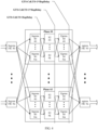
- step S101 to step S104 in FIG. 2 is not limited to being used in a single-chassis system (including only a link on a TxToFic side), but may also be used in a multi-level multi-chassis system (including a link on a TxToSe side and a link on a TxToFic side).
- TxToFic refers to a link for transmission to a lower-level node being an FIC
- TxToSe refers to a link for transmission to a lower-level node being an SE. Details are as follows.
- the target cell is sent to the lower-level node when GTS minus Cell.TS is greater than HopDelay in the target cell.
- the target cell is sent to the lower-level node when GTS minus Cell.TS is greater than 2 ⁇ HopDelay in the target cell.
- the target cell is sent to the lower-level node when GTS minus Cell.TS is greater than 3 ⁇ HopDelay in the target cell.
- the sending delay threshold may be determined based on a communication delay between the first node and the lower-level node (namely, the egress FIC).
- the target cell is sent to the egress FIC based on the system moment, the target moment, and the sending delay threshold.
- a corresponding target cell is sent to the lower-level node when GTS minus Cell.TS is greater than HopDelay+Tx_Delay_1m in the target cell, and a corresponding target cell is sent to another lower-level node when GTS minus Cell.TS is greater than HopDelay+TxDelay_100m in the target cell.
- a corresponding target cell is sent to the lower-level node when GTS minus Cell.TS is greater than HopDelay+Tx_Delay_20m in the target cell, and a corresponding target cell is sent to another lower-level node when GTS minus Cell.TS is greater than HopDelay+Tx_Delay_80m in the target cell.
- a corresponding target cell is sent to the lower-level node when GTS minus Cell.TS is greater than HopDelay+TxDelay_100m in the target cell, and a corresponding target cell is sent to another lower-level node when GTS minus Cell.TS is greater than HopDelay+TxDelay_1m in the target cell.
- a difference between output times of the first nodes can be reduced.
- OQ resources of the first node can share sorting load corresponding to IQ resources of some lower-level nodes, to help optimize sorting resources of the FIC/SE (this helps reduce chip costs or ensure engineering implementation).
- system expansibility can be improved, to support a more flexible networking structure (for example, link asymmetric extension).
- the first node in the switching network system obtains the to-be-sent target cell and the target moment, where the target moment is used to indicate the moment at which the target cell is processed. Then, the first node determines the sending delay threshold of the target cell. In addition, the first node obtains the current system moment in the first node. Thereafter, the first node sends the target cell to the lower-level node when the difference between the system moment and the target moment is greater than the sending delay threshold. The first node obtains the target cell and the target moment.
- the first node sends the target cell to the lower-level node in the switching network system
- the first node sends the target cell to the lower-level node only when the difference between the system moment and the target moment is greater than the sending delay threshold.
- the first node delays, by using the sending delay threshold, sending the target cell, so that an upper-level node in the switching network system shares sorting load of a lower-level node, to avoid an increased transmission delay caused by back pressure of the lower-level node, optimize sorting resources between different levels of nodes in the switching network system, and improve stability of the switching network system.
- an embodiment of this application provides a communication apparatus 600.
- the communication apparatus 600 may be a first node.
- the communication apparatus 600 includes an obtaining unit 601, a determining unit 602, a sending unit 603, a receiving unit 604, and an updating unit 605.
- the obtaining unit 601 is configured to obtain a to-be-sent target cell and a target moment, where the target moment is used to indicate a moment at which the target cell is processed.
- the determining unit 602 is configured to determine a sending delay threshold of the target cell.
- the obtaining unit 601 is further configured to obtain a current system moment in the first node.
- the sending unit 603 is configured to send the target cell to a lower-level node when a difference between the system moment and the target moment is greater than the sending delay threshold.
- the determining unit 602 is specifically configured to:
- the determining unit 602 is specifically configured to:
- the determining unit 602 is specifically configured to:
- the apparatus further includes:
- the sending unit 603 is specifically configured to: send the target cell to the lower-level node when the difference between the system moment and the target moment is greater than the updated sending delay threshold.
- the obtaining unit 601 is specifically configured to:
- the obtaining unit 601 is specifically configured to: receive the target cell and the target moment that are sent by an upper-level node, where the target moment is used to indicate a moment at which the upper-level node receives the target cell, or the target moment is used to indicate a moment at which the upper-level node sends the target cell, or the target moment is used to indicate a moment at which the initial node in the switching network system generates the target cell, or the target moment is used to indicate a moment at which the initial node in the switching network system sends the target cell.
- the sending unit 603 is specifically configured to: send the target cell and the target moment to the lower-level node.
- the sending unit 603 is specifically configured to:
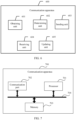
- FIG. 7 is a schematic diagram of a possible logical structure of a communication apparatus 700 in the foregoing embodiments according to an embodiment of this application.
- the communication apparatus may be specifically the first node in the foregoing embodiments.
- the communication apparatus 700 may include but is not limited to a processor 701, a communication port 702, a memory 703, and a bus 704.
- the processor 701 is configured to control and process an action of the communication apparatus 700.
- the processor 701 may be a central processing unit, a general-purpose processor, a digital signal processor, an application-specific integrated circuit, a field programmable gate array, another programmable logic device, a transistor logic device, a hardware component, or any combination thereof.
- the processor system may implement or execute various example logical blocks, modules, and circuits described with reference to content disclosed in this application.
- the processor may be a combination of processors implementing a computing function, for example, a combination of one or more microprocessors, or a combination of a digital signal processor and a microprocessor.
- the communication apparatus shown in FIG. 7 may be specifically configured to implement steps implemented by the terminal device in the method embodiments corresponding to FIG. 2 to FIG. 5 , and implement technical effects corresponding to the first node. Details are not described herein.
- An embodiment of this application further provides a computer-readable storage medium storing one or more computer-executable instructions.
- the processor When the one or more computer-executable instructions are executed by a processor, the processor performs the method according to the possible implementation of the communication apparatus in the foregoing embodiment.
- the communication apparatus may be specifically the first node in the method embodiments corresponding to FIG. 2 to FIG. 5 .
- An embodiment of this application further provides a computer program product (or referred to as a computer program) storing one or more computers.
- a computer program product (or referred to as a computer program) storing one or more computers.
- the processor When the computer program product is executed by a processor, the processor performs the method according to the possible implementation of the communication apparatus.
- the communication apparatus may be specifically the first node in the method embodiments corresponding to FIG. 2 to FIG. 5 .
- An embodiment of this application further provides a computer program product storing one or more computers.
- the processor When the computer program product is executed by a processor, the processor performs the method according to the possible implementation of the communication apparatus.
- the communication apparatus may be specifically the first node in the method embodiments corresponding to FIG. 2 to FIG. 5 .
- An embodiment of this application further provides a chip system, and the chip system includes a processor, configured to support a communication apparatus in implementing the functions in the possible implementation of the communication apparatus.
- the chip system may further include a memory, and the memory is configured to store program instructions and data that are necessary for the communication apparatus.
- the chip system may include a chip, or may include a chip and another discrete device.
- the communication apparatus may be specifically the first node in the method embodiments corresponding to FIG. 2 to FIG. 5 .
- An embodiment of this application further provides a network system architecture.
- the network system architecture includes the foregoing communication apparatus, which may be specifically the first node in the method embodiments corresponding to FIG. 2 to FIG. 5 ; and a possible third node.
- the disclosed system, apparatus, and method may be implemented in other manners.
- the described apparatus embodiment is merely an example.
- division into the units is merely logical function division and may be other division during actual implementation.
- a plurality of units or components may be combined or integrated into another system, or some features may be ignored or not performed.
- the displayed or discussed mutual couplings or direct couplings or communication connections may be implemented through some interfaces.
- the indirect couplings or communication connections between the apparatuses or units may be implemented in electrical, mechanical, or another form.
- the units described as separate parts may or may not be physically separate, and parts displayed as units may or may not be physical units, may be located in one position, or may be distributed on a plurality of network units. Some or all of the units may be selected based on actual requirements to achieve the objectives of the solutions of embodiments.
- functional units in the embodiments of this application may be integrated into one processing unit, or each of the units may exist alone physically, or two or more units may be integrated into one unit.
- the integrated unit may be implemented in a form of hardware, or may be implemented in a form of a software functional unit.
- the integrated unit When the integrated unit is implemented in the form of the software functional unit and sold or used as an independent product, the integrated unit may be stored in a computer-readable storage medium.
- the computer software product is stored in a storage medium and includes several instructions for instructing a computer device (which may be a personal computer, a server, or a network device) to perform all or some of the steps of the methods described in embodiments of this application.
- the storage medium includes any medium that can store program code, such as a USB flash drive, a removable hard disk, a read-only memory (ROM, Read-Only Memory), a random access memory (RAM, Random Access Memory), a magnetic disk, or an optical disc.
Landscapes
- Engineering & Computer Science (AREA)
- Computer Networks & Wireless Communication (AREA)
- Signal Processing (AREA)
- Data Exchanges In Wide-Area Networks (AREA)
- Mobile Radio Communication Systems (AREA)
Applications Claiming Priority (1)
| Application Number | Priority Date | Filing Date | Title |
|---|---|---|---|
| PCT/CN2020/099134 WO2022000234A1 (fr) | 2020-06-30 | 2020-06-30 | Procédé de communication et appareil associé |
Publications (3)
| Publication Number | Publication Date |
|---|---|
| EP4170980A1 true EP4170980A1 (fr) | 2023-04-26 |
| EP4170980A4 EP4170980A4 (fr) | 2023-08-16 |
| EP4170980B1 EP4170980B1 (fr) | 2026-03-25 |
Family
ID=79317687
Family Applications (1)
| Application Number | Title | Priority Date | Filing Date |
|---|---|---|---|
| EP20943639.3A Active EP4170980B1 (fr) | 2020-06-30 | 2020-06-30 | Procédé de communication et appareil associé |
Country Status (3)
| Country | Link |
|---|---|
| EP (1) | EP4170980B1 (fr) |
| CN (1) | CN115868145B (fr) |
| WO (1) | WO2022000234A1 (fr) |
Family Cites Families (10)
| Publication number | Priority date | Publication date | Assignee | Title |
|---|---|---|---|---|
| JP4020258B2 (ja) * | 2003-08-25 | 2007-12-12 | 株式会社エヌ・ティ・ティ・ドコモ | フレーム転送装置、フレーム転送方法 |
| CN100461748C (zh) * | 2004-10-22 | 2009-02-11 | 华为技术有限公司 | 直接互连交换网路由的方法 |
| US7813736B2 (en) * | 2006-06-28 | 2010-10-12 | At&T Intellectual Property I, L.P. | Method and apparatus for improving network performance in a communication system |
| CN101282230B (zh) * | 2007-04-05 | 2011-04-20 | 中兴通讯股份有限公司 | 广播数据全网同步的实现方法 |
| EP2736197B1 (fr) * | 2011-08-17 | 2016-03-09 | Huawei Technologies Co., Ltd. | Procédé de réassemblage et de reséquençage de paquet, et appareil et système associés |
| CN107070805A (zh) * | 2017-03-22 | 2017-08-18 | 上海华为技术有限公司 | 一种流量控制的方法及节点 |
| US11314772B2 (en) * | 2017-04-26 | 2022-04-26 | Telefonaktiebolaget Lm Ericsson (Publ) | Robust data replication among data centers |
| CN109428742B (zh) * | 2017-08-22 | 2020-12-15 | 华为技术有限公司 | 基于时延传输路径控制方法、网络控制器和系统 |
| KR102423374B1 (ko) * | 2017-09-14 | 2022-07-21 | 삼성전자주식회사 | 무선 통신 시스템에서 예약 신호를 송신하기 위한 장치 및 방법 |
| CN110505155B (zh) * | 2019-08-13 | 2023-12-08 | 北京达佳互联信息技术有限公司 | 请求降级处理方法、装置、电子设备及存储介质 |
-
2020
- 2020-06-30 WO PCT/CN2020/099134 patent/WO2022000234A1/fr not_active Ceased
- 2020-06-30 EP EP20943639.3A patent/EP4170980B1/fr active Active
- 2020-06-30 CN CN202080102361.0A patent/CN115868145B/zh active Active
Also Published As
| Publication number | Publication date |
|---|---|
| CN115868145B (zh) | 2025-07-25 |
| EP4170980B1 (fr) | 2026-03-25 |
| WO2022000234A1 (fr) | 2022-01-06 |
| EP4170980A4 (fr) | 2023-08-16 |
| CN115868145A (zh) | 2023-03-28 |
Similar Documents
| Publication | Publication Date | Title |
|---|---|---|
| EP2453612B1 (fr) | Dispositif de commande de bus | |
| US9600440B2 (en) | Network topology of hierarchical ring with recursive shortcuts | |
| US6950395B1 (en) | Method and apparatus for a token bucket metering or policing system with a delayed filling scheme | |
| AU2021104939A4 (en) | Method and device for allocating resources | |
| US10693774B1 (en) | Modular architecture for computer network operations | |
| CN116055426B (zh) | 用于多绑定模式下流量卸载转发的方法、设备及介质 | |
| US11102106B2 (en) | Dynamic flooding for link state protocols | |
| CN113765956B (zh) | 报文处理方法、设备、系统及存储介质 | |
| CN112511253B (zh) | 一种同步方法、装置、设备和存储介质 | |
| WO2004040858A1 (fr) | Repartition de charge dynamique faisant appel a des informations d'etat locales | |
| CN114938327A (zh) | 路由方法、路由装置、控制器和计算机可读存储介质 | |
| CN113612698A (zh) | 一种数据包发送方法及装置 | |
| US8139499B2 (en) | Method and arrangement for determining transmission delay differences | |
| EP3515018A1 (fr) | Procédé, appareil et système de mesure de trajet de réseau | |
| EP4170980B1 (fr) | Procédé de communication et appareil associé | |
| CN112887353B (zh) | 一种信息处理方法、装置、终端及存储介质 | |
| CN114389733B (zh) | Ptp主时钟设备、时钟同步方法及存储介质 | |
| JP2015536621A (ja) | 受動接続性光学モジュール | |
| WO2024021878A1 (fr) | Procédé d'envoi d'informations de charge, procédé d'envoi d'un message et appareil associé | |
| US11996932B2 (en) | Active-active TDM PW with asymmetry control | |
| JP2005277915A (ja) | パケット振り分け方法及び振り分け装置 | |
| CN112583746A (zh) | 信元传输方法及装置、存储介质、电子装置 | |
| WO2025046732A1 (fr) | Émettteur | |
| EP4735970A1 (fr) | Système et procédés pour des réseaux de centres de données optiques à commutation rapide | |
| CN118282550A (zh) | 一种时钟源的确定方法、网络设备及网络管理设备 |
Legal Events
| Date | Code | Title | Description |
|---|---|---|---|
| STAA | Information on the status of an ep patent application or granted ep patent |
Free format text: STATUS: THE INTERNATIONAL PUBLICATION HAS BEEN MADE |
|
| PUAI | Public reference made under article 153(3) epc to a published international application that has entered the european phase |
Free format text: ORIGINAL CODE: 0009012 |
|
| STAA | Information on the status of an ep patent application or granted ep patent |
Free format text: STATUS: REQUEST FOR EXAMINATION WAS MADE |
|
| 17P | Request for examination filed |
Effective date: 20230117 |
|
| AK | Designated contracting states |
Kind code of ref document: A1 Designated state(s): AL AT BE BG CH CY CZ DE DK EE ES FI FR GB GR HR HU IE IS IT LI LT LU LV MC MK MT NL NO PL PT RO RS SE SI SK SM TR |
|
| REG | Reference to a national code |
Ref country code: DE Ref legal event code: R079 Free format text: PREVIOUS MAIN CLASS: H04L0012540000 Ipc: H04L0012400000 Ref document number: 602020069407 Country of ref document: DE |
|
| A4 | Supplementary search report drawn up and despatched |
Effective date: 20230713 |
|
| RIC1 | Information provided on ipc code assigned before grant |
Ipc: H04L 12/40 20060101AFI20230707BHEP |
|
| DAV | Request for validation of the european patent (deleted) | ||
| DAX | Request for extension of the european patent (deleted) | ||
| STAA | Information on the status of an ep patent application or granted ep patent |
Free format text: STATUS: EXAMINATION IS IN PROGRESS |
|
| 17Q | First examination report despatched |
Effective date: 20250113 |
|
| GRAP | Despatch of communication of intention to grant a patent |
Free format text: ORIGINAL CODE: EPIDOSNIGR1 |
|
| STAA | Information on the status of an ep patent application or granted ep patent |
Free format text: STATUS: GRANT OF PATENT IS INTENDED |
|
| INTG | Intention to grant announced |
Effective date: 20251118 |
|
| GRAS | Grant fee paid |
Free format text: ORIGINAL CODE: EPIDOSNIGR3 |
|
| GRAA | (expected) grant |
Free format text: ORIGINAL CODE: 0009210 |
|
| STAA | Information on the status of an ep patent application or granted ep patent |
Free format text: STATUS: THE PATENT HAS BEEN GRANTED |
|
| AK | Designated contracting states |
Kind code of ref document: B1 Designated state(s): AL AT BE BG CH CY CZ DE DK EE ES FI FR GB GR HR HU IE IS IT LI LT LU LV MC MK MT NL NO PL PT RO RS SE SI SK SM TR |
|
| REG | Reference to a national code |
Ref country code: CH Ref legal event code: F10 Free format text: ST27 STATUS EVENT CODE: U-0-0-F10-F00 (AS PROVIDED BY THE NATIONAL OFFICE) Effective date: 20260325 Ref country code: GB Ref legal event code: FG4D |
|
| REG | Reference to a national code |
Ref country code: DE Ref legal event code: R096 Ref document number: 602020069407 Country of ref document: DE |
|
| REG | Reference to a national code |
Ref country code: IE Ref legal event code: FG4D |
|
| PG25 | Lapsed in a contracting state [announced via postgrant information from national office to epo] |
Ref country code: RS Free format text: LAPSE BECAUSE OF FAILURE TO SUBMIT A TRANSLATION OF THE DESCRIPTION OR TO PAY THE FEE WITHIN THE PRESCRIBED TIME-LIMIT Effective date: 20260625 |
|
| PGFP | Annual fee paid to national office [announced via postgrant information from national office to epo] |
Ref country code: GB Payment date: 20260511 Year of fee payment: 7 |
|
| PG25 | Lapsed in a contracting state [announced via postgrant information from national office to epo] |
Ref country code: GR Free format text: LAPSE BECAUSE OF FAILURE TO SUBMIT A TRANSLATION OF THE DESCRIPTION OR TO PAY THE FEE WITHIN THE PRESCRIBED TIME-LIMIT Effective date: 20260626 |
|
| REG | Reference to a national code |
Ref country code: LT Ref legal event code: MG9D |
|
| PG25 | Lapsed in a contracting state [announced via postgrant information from national office to epo] |
Ref country code: LT Free format text: LAPSE BECAUSE OF FAILURE TO SUBMIT A TRANSLATION OF THE DESCRIPTION OR TO PAY THE FEE WITHIN THE PRESCRIBED TIME-LIMIT Effective date: 20260325 |
|
| PGFP | Annual fee paid to national office [announced via postgrant information from national office to epo] |
Ref country code: DE Payment date: 20260506 Year of fee payment: 7 |
|
| PG25 | Lapsed in a contracting state [announced via postgrant information from national office to epo] |
Ref country code: NO Free format text: LAPSE BECAUSE OF FAILURE TO SUBMIT A TRANSLATION OF THE DESCRIPTION OR TO PAY THE FEE WITHIN THE PRESCRIBED TIME-LIMIT Effective date: 20260625 |
|
| PG25 | Lapsed in a contracting state [announced via postgrant information from national office to epo] |
Ref country code: SE Free format text: LAPSE BECAUSE OF FAILURE TO SUBMIT A TRANSLATION OF THE DESCRIPTION OR TO PAY THE FEE WITHIN THE PRESCRIBED TIME-LIMIT Effective date: 20260325 Ref country code: FI Free format text: LAPSE BECAUSE OF FAILURE TO SUBMIT A TRANSLATION OF THE DESCRIPTION OR TO PAY THE FEE WITHIN THE PRESCRIBED TIME-LIMIT Effective date: 20260325 |
|
| PG25 | Lapsed in a contracting state [announced via postgrant information from national office to epo] |
Ref country code: HR Free format text: LAPSE BECAUSE OF FAILURE TO SUBMIT A TRANSLATION OF THE DESCRIPTION OR TO PAY THE FEE WITHIN THE PRESCRIBED TIME-LIMIT Effective date: 20260325 |
|
| PG25 | Lapsed in a contracting state [announced via postgrant information from national office to epo] |
Ref country code: LV Free format text: LAPSE BECAUSE OF FAILURE TO SUBMIT A TRANSLATION OF THE DESCRIPTION OR TO PAY THE FEE WITHIN THE PRESCRIBED TIME-LIMIT Effective date: 20260325 |
|
| PG25 | Lapsed in a contracting state [announced via postgrant information from national office to epo] |
Ref country code: BG Free format text: LAPSE BECAUSE OF FAILURE TO SUBMIT A TRANSLATION OF THE DESCRIPTION OR TO PAY THE FEE WITHIN THE PRESCRIBED TIME-LIMIT Effective date: 20260325 |
|
| REG | Reference to a national code |
Ref country code: NL Ref legal event code: MP Effective date: 20260325 |