EP4171004B1 - Appareil de traitement d'image, système de traitement d'informations, procédé de traitement d'image et moyens de support - Google Patents
Appareil de traitement d'image, système de traitement d'informations, procédé de traitement d'image et moyens de support Download PDFInfo
- Publication number
- EP4171004B1 EP4171004B1 EP22197801.8A EP22197801A EP4171004B1 EP 4171004 B1 EP4171004 B1 EP 4171004B1 EP 22197801 A EP22197801 A EP 22197801A EP 4171004 B1 EP4171004 B1 EP 4171004B1
- Authority
- EP
- European Patent Office
- Prior art keywords
- value
- gradation
- colorimetric
- gray
- target
- Prior art date
- Legal status (The legal status is an assumption and is not a legal conclusion. Google has not performed a legal analysis and makes no representation as to the accuracy of the status listed.)
- Active
Links
Images







Classifications
-
- H—ELECTRICITY
- H04—ELECTRIC COMMUNICATION TECHNIQUE
- H04N—PICTORIAL COMMUNICATION, e.g. TELEVISION
- H04N1/00—Scanning, transmission or reproduction of documents or the like, e.g. facsimile transmission; Details thereof
- H04N1/46—Colour picture communication systems
- H04N1/56—Processing of colour picture signals
- H04N1/60—Colour correction or control
- H04N1/6027—Correction or control of colour gradation or colour contrast
-
- H—ELECTRICITY
- H04—ELECTRIC COMMUNICATION TECHNIQUE
- H04N—PICTORIAL COMMUNICATION, e.g. TELEVISION
- H04N1/00—Scanning, transmission or reproduction of documents or the like, e.g. facsimile transmission; Details thereof
- H04N1/46—Colour picture communication systems
- H04N1/56—Processing of colour picture signals
- H04N1/60—Colour correction or control
- H04N1/6002—Corrections within particular colour systems
- H04N1/6008—Corrections within particular colour systems with primary colour signals, e.g. RGB or CMY(K)
-
- H—ELECTRICITY
- H04—ELECTRIC COMMUNICATION TECHNIQUE
- H04N—PICTORIAL COMMUNICATION, e.g. TELEVISION
- H04N1/00—Scanning, transmission or reproduction of documents or the like, e.g. facsimile transmission; Details thereof
- H04N1/46—Colour picture communication systems
- H04N1/56—Processing of colour picture signals
- H04N1/60—Colour correction or control
- H04N1/603—Colour correction or control controlled by characteristics of the picture signal generator or the picture reproducer
- H04N1/6033—Colour correction or control controlled by characteristics of the picture signal generator or the picture reproducer using test pattern analysis
-
- H—ELECTRICITY
- H04—ELECTRIC COMMUNICATION TECHNIQUE
- H04N—PICTORIAL COMMUNICATION, e.g. TELEVISION
- H04N2201/00—Indexing scheme relating to scanning, transmission or reproduction of documents or the like, and to details thereof
- H04N2201/0001—Diagnosis, testing or measuring; Detecting, analysis or monitoring not otherwise provided for
- H04N2201/0003—Method used
- H04N2201/0005—Method used using a reference pattern designed for the purpose, e.g. a test chart
Definitions
- the present invention relates to an image processing apparatus, an information processing system, an image processing method, and carrier means.
- a printed material output from an image forming apparatus changes in color over time.
- color matching is periodically performed.
- the periodic color matching involves appropriate color matching of grays, which are mixtures of cyan (C), magenta (M), and yellow (Y).
- grays which are mixtures of cyan (C), magenta (M), and yellow (Y).
- color matching to address a change in color mixture over time, colors adjacent to the colors to be subjected to color matching are output and colorimetric values thereof are acquired to identify the direction of color matching.
- JP-B-4751853 A technique for such color matching is disclosed in JP-B-4751853 , for example.
- a gray adjacent to a target gray is output to measure a color mixing characteristic, and the target gray is corrected to a target value using the measurement result.
- JP-A-2020-151967 discloses a technique for correcting colorimetric values acquired from an image during a print job to target values for calibration by using a prediction model created at the time of calibration to address a change in gradation characteristic.
- JP-B- 4751853 imposes a heavy load on a user who performs color measurement of adjacent grays each time correction is performed.
- the colorimetric values in the current state are made to match the target values in the past state, where the past state is the state at calibration and the current state is the state at print job processing.
- a large change in color mixing characteristic between the calibration time and the print job processing time makes accurate correction difficult.
- JP-A-2007174125 discloses a method in which a user records an image for ascertaining the state of gray, subjects the image to colorimetrics processing, and acquires image data. Then, a point at which a gray adjustment is required is designated, a colormetrics adjustment target value for the designated point is calculated from data representing gray near to the shade of gray at the designated point resting on the basis of the obtained image data. Furthermore, image data representing gray modifying patches used for gray adjustments made for the designated point are formed on the basis of data representing the gray at the designated point, and the modifying patches are recorded. The gray patches are recorded and subjected to colorimetrics processing. Lastly, a patch close to the modifying target value is selected from the peripheral patches to adjust gray.
- an object of the present invention is to provide an image processing apparatus, an information processing system, an image processing method, and carrier means for accurate correction of color mixtures while keeping the load of a color measurement process low for each correction.
- the invention provides an image processing apparatus in accordance with claim 1 and a method in accordance with claim 6.
- An embodiment of the present invention includes carrier means carrying computer readable codes for controlling a computer system to carry out the above-described image processing method.
- color mixtures are accurately corrected while keeping the load of a color measurement process low for each correction.
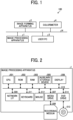
- FIG. 1 is a diagram illustrating an example general arrangement of an information processing system 100 according to a first embodiment. The general arrangement of the information processing system 100 according to this embodiment will be described with reference to FIG. 1 .
- the information processing system 100 includes an image processing apparatus 1, an image forming apparatus 2, a user personal computer (PC) 3, and a colorimeter 4.
- the image processing apparatus 1, the image forming apparatus 2, the user PC 3, and the colorimeter 4 can perform data communication via a network N.
- the network N is a network such as a local area network (LAN).
- the network N may be a wired network or a wireless network.
- the image processing apparatus 1 is an apparatus that performs color matching (correction process) of grays, which are mixtures of cyan (C), magenta (M), and yellow (Y), on a printed material to be output from the image forming apparatus 2.
- the image processing apparatus 1 may be, for example, an information processing apparatus such as a general-purpose PC.
- the image forming apparatus 2 is a printing machine for commercial use, and the image processing apparatus 1 is a digital front end (DFE).
- DFE digital front end
- the color mixtures will be described as grays containing three colors of C, M, Y, as described above, as a non-limiting example.
- the color mixtures may be secondary colors or other mixtures of colors.
- the image forming apparatus 2 is an apparatus that prints out an image based on image data output from the user PC 3 and subjected to image processing by the image processing apparatus 1.
- the user PC 3 is an information processing apparatus that transmits image data to be printed to the image processing apparatus 1.
- the colorimeter 4 is a device for performing color measurement on a chart printed out from the image forming apparatus 2.
- the colorimeter 4 transmits colorimetric values obtained by color measurement on the chart to the image processing apparatus 1. Examples of the colorimetric values include Lab values (color values) in the L*a*b* color space.
- the colorimeter 4 may be a device that automatically reads a printed chart placed thereon or a device that reads a printed chart by a manual operation.
- FIG. 2 is a diagram illustrating an example hardware configuration of the image processing apparatus 1 according to the first embodiment.
- the hardware configuration of the image processing apparatus 1 according to this embodiment will be described with reference to FIG. 2 .
- the image processing apparatus 1 includes a central processing unit (CPU) 501, a read only memory (ROM) 502, a random access memory (RAM) 503, an auxiliary storage device 505, a media drive 507, a display 508, a network interface (I/F) 509, a keyboard 511, a mouse 512, and a digital versatile disc (DVD) drive 514.
- CPU central processing unit
- ROM read only memory
- RAM random access memory
- I/F network interface
- keyboard 511 a mouse 512
- DVD digital versatile disc
- the CPU 501 is an arithmetic processor that controls the overall operation of the image processing apparatus 1.
- the ROM 502 is a non-volatile storage device that stores a program initially executed by the CPU 501. Examples of such a program include an initial program loader (IPL).
- the RAM 503 is a volatile storage device used as a work area for the CPU 501.
- the auxiliary storage device 505 is a non-volatile storage device that stores various data such as a program. Examples of the auxiliary storage device 505 include a hard disk drive (HDD) and a solid state drive (SSD).
- HDD hard disk drive
- SSD solid state drive
- the media drive 507 is a device that controls reading or writing of data from or to a recording medium 506 such as a flash memory.
- the display 508 displays various types of information such as a cursor, a menu, a window, text, or an image.
- Examples of the display 508 include a liquid crystal display (LCD) and an organic electro-luminescence (EL) display.
- LCD liquid crystal display
- EL organic electro-luminescence
- the network I/F 509 is an interface for performing data communication using the network N.
- the network I/F 509 is a network interface card (NIC) or the like that enables communication using a protocol such as the transmission control protocol/Internet protocol (TCP/IP).
- the network I/F 509 may be a communication interface having a wireless communication function based on a standard such as Wireless Fidelity (Wi-Fi ® ).
- the keyboard 511 is one example of an input device provided with a plurality of keys for inputting characters, numerical values, various instructions, or the like.
- the mouse 512 is a type of input device operated by a user to select or execute various instructions, select a target for processing, and move a cursor being displayed, for example.
- the DVD drive 514 is a device that controls reading or writing of various data from or to a DVD 513, which is an example of a removable recording medium.
- Examples of the DVD 513 include a digital versatile disc rewritable (DVD-RW), a digital versatile disc recordable (DVD-R), a compact disc rewritable (CD-RW), and a compact disc recordable (CD-R).
- the CPU 501, the ROM 502, the RAM 503, the auxiliary storage device 505, the media drive 507, the display 508, the network I/F 509, the keyboard 511, the mouse 512, and the DVD drive 514 described above are communicably connected to each other via a bus line 510 such as an address bus and a data bus.
- the hardware configuration of the image processing apparatus 1 illustrated in FIG. 2 is an example. Not all of the components described above may be included in the image processing apparatus 1, and the image processing apparatus 1 may include any other component.
- the user PC 3 has a hardware configuration similar to that illustrated in FIG. 2 .
- FIG. 3 is a diagram illustrating an example hardware configuration of the image forming apparatus 2 according to the first embodiment. The hardware configuration of the image forming apparatus 2 will be described with reference to FIG. 3 .
- the image forming apparatus 2 includes a controller 600, an operation display unit 610, a facsimile control unit (FCU) 620, a plotter 631, and a scanner 632.
- the controller 600, the operation display unit 610, the FCU 620, the plotter 631, and the scanner 632 are interconnected by a peripheral component interface (PCI) bus.
- PCI peripheral component interface
- the controller 600 is a device that controls the overall operation of the image forming apparatus 2. For example, the controller 600 controls drawing, communication, and input from the operation display unit 610.
- the operation display unit 610 is a device that accepts an input to the controller 600 (input function) and displays the state of the image forming apparatus 2 and other information on the image forming apparatus 2 (display function). Examples of the operation display unit 610 include a touch panel.
- the operation display unit 610 is directly connected to an application specific integrated circuit (ASIC) 606 described below.
- ASIC application specific integrated circuit
- the FCU 620 is a device that implements a facsimile function, and is connected to the ASIC 606 via, for example, a PCI bus.
- the plotter 631 is a device that implements a print function, and is connected to the ASIC 606 via, for example, a PCI bus.
- the scanner 632 is a device that implements a scanner function, and is connected to the ASIC 606 via, for example, a PCI bus.
- the controller 600 includes a CPU 601, a system memory (MEM-P) 602, a northbridge (NB) 603, a southbridge (SB) 604a, a network I/F 604b, a Universal Serial Bus (USB) I/F 604c, a Centronics I/F 604d, a sensor I/F 604e, the ASIC 606, a local memory (MEM-C) 607, and an auxiliary storage device 608.
- MEM-P system memory
- NB northbridge
- SB southbridge
- USB Universal Serial Bus
- the CPU 601 is an arithmetic processor that performs overall control of the image forming apparatus 2.
- the CPU 601 is connected to a chipset including the system memory 602, the northbridge 603, and the southbridge 604a and is connected to another device via the chipset.
- the system memory 602 is used as a memory for storing programs and data, a memory for loading programs and data, and a memory for storing drawing data of a printer, for example.
- the system memory 602 includes a ROM and a RAM.
- the ROM is a read-only memory for storing programs and data.
- the RAM is a writable and readable memory for loading programs and data and storing drawing data of the printer, for example.
- the northbridge 603 is a bridge for connecting the CPU 601 to the system memory 602, the southbridge 604a, and an accelerated graphics port (AGP) bus 605.
- the northbridge 603 includes a memory controller that controls reading and writing of data from and to the system memory 602.
- the northbridge 603 further includes a PCI master and an AGP target.
- the southbridge 604a is a bridge for connecting the northbridge 603 to PCI devices and peripheral devices.
- the southbridge 604a is connected to the northbridge 603 via a PCI bus, and the PCI bus is connected to the network I/F 604b, the USB I/F 604c, the Centronics I/F 604d, and the sensor I/F 604e, for example.
- the AGP bus 605 is a bus interface for a graphics accelerator card to accelerate graphics processing.
- the AGP bus 605 can speed up the graphics accelerator card by directly accessing the system memory 602 with high throughput.
- the ASIC 606 is an integrated circuit (IC) for use in image processing and includes hardware elements for image processing.
- the ASIC 606 serves as a bridge for connecting the AGP bus 605, the PCI bus, the auxiliary storage device 608, and the local memory 607 to each other.
- the ASIC 606 includes a PCI target, an AGP master, an arbiter (ARB) as a core of the ASIC 606, a memory controller, a plurality of direct memory access controllers (DMACs), and a PCI unit.
- the memory controller controls the local memory 607.
- the DMACs are configured to, for example, rotate image data with a hardware logic.
- the PCI unit transfers data to the plotter 631 and the scanner 632 via a PCI bus.
- the ASIC 606 is connected to, for example, the FCU 620, the plotter 631, and the scanner 632 via a PCI bus.
- the local memory 607 is used as a copy image buffer and a code buffer.
- the auxiliary storage device 608 is a storage device such as an HDD, an SSD, a Secure Digital (SD) card, or a flash memory.
- the auxiliary storage device 608 stores image data, programs, font data, and forms.
- the hardware configuration of the image forming apparatus 2 illustrated in FIG. 3 is an example. Not all of the components described above may be included in the image forming apparatus 2, and the image forming apparatus 2 may include any other component.
- the image forming apparatus 2 includes an automatic document feeder (ADF).
- ADF automatic document feeder
- FIG. 4 is a diagram illustrating an example configuration of functional blocks of the image processing apparatus 1 according to the first embodiment. The configuration and operation of the functional blocks of the image processing apparatus 1 according to this embodiment will be described with reference to FIG. 4 .
- the image processing apparatus 1 includes a colorimetric value acquisition unit 11, a prediction model creation unit 12 (second acquisition unit, creation unit), a target acquisition unit 13 (first acquisition unit), a storage unit 14, a tone reproduction curve (TRC) generation unit 15 (third acquisition unit, first calculation unit, first determination unit, fourth acquisition unit), a chart image generation unit 16, an image input unit 17, an image processing unit 18 (correction unit), and an image output unit 19.
- a colorimetric value acquisition unit 11 a prediction model creation unit 12 (second acquisition unit, creation unit), a target acquisition unit 13 (first acquisition unit), a storage unit 14, a tone reproduction curve (TRC) generation unit 15 (third acquisition unit, first calculation unit, first determination unit, fourth acquisition unit), a chart image generation unit 16, an image input unit 17, an image processing unit 18 (correction unit), and an image output unit 19.
- TRC tone reproduction curve
- the colorimetric value acquisition unit 11 is a functional unit that acquires colorimetric values via the network I/F 509.
- the colorimetric values are obtained by the colorimeter 4 performing color measurement on a chart printed by the image forming apparatus 2.
- the colorimetric value acquisition unit 11 is implemented by, for example, the CPU 501 illustrated in FIG. 2 executing a program.
- the prediction model creation unit 12 is a functional unit that creates a prediction model, based on the colorimetric values acquired by the colorimetric value acquisition unit 11.
- the prediction model is used to predict a colorimetric value from the dot area ratio of a color.
- the prediction model creation unit 12 creates a prediction model serving as a learning model by a learning process based on supervised learning or the like.
- the prediction model creation unit 12 creates respective prediction models for dot area ratios of target grays, which will be described below, and stores the prediction models in the storage unit 14.
- the dot area ratios may be referred to as device values.
- the prediction model creation unit 12 is implemented by, for example, the CPU 501 illustrated in FIG. 2 executing a program.
- the target acquisition unit 13 is a functional unit that acquires target single colors and target grays from the colorimetric values acquired by the colorimetric value acquisition unit 11.
- Each of the target single colors is a target value of a corresponding one of the single colors of CMY.
- the target grays are target values of grays that are mixed colors.
- the target values are each indicated by, for example, a density, a distance from paper white, or the like.
- the target acquisition unit 13 stores the acquired target single colors and target grays in the storage unit 14.
- the target acquisition unit 13 is implemented by, for example, the CPU 501 illustrated in FIG. 2 executing a program.
- the storage unit 14 is a functional unit that stores prediction models, various TRCs, and the like.
- the storage unit 14 is implemented by the RAM 503 or the auxiliary storage device 505 illustrated in FIG. 2 .
- the TRC generation unit 15 is a functional unit that generates single-color TRCs, based on the colorimetric values of the single colors acquired by the colorimetric value acquisition unit 11 and the target single colors stored in the storage unit 14. Further, the TRC generation unit 15 generates gray-corrected single-color TRCs, based on pre-correction grays and the target grays and the prediction models stored in the storage unit 14. The pre-correction grays are acquired by the colorimetric value acquisition unit 11 at a correction time. The details of the single-color TRCs and the gray-corrected single-color TRCs will be described below. Like the target grays, the pre-correction grays are each indicated by, for example, a density, a distance from paper white, or the like.
- the TRC is a one-dimensional conversion curve for converting an input gradation into an output gradation.
- the TRC generation unit 15 is implemented by, for example, the CPU 501 illustrated in FIG. 2 executing a program.
- the chart image generation unit 16 is a functional unit that generates a chart image.
- the chart image is used to acquire the target grays, create the prediction models, and perform a gray correction process.
- the chart image generation unit 16 is implemented by, for example, the CPU 501 illustrated in FIG. 2 executing a program.
- the image input unit 17 is a functional unit that receives input of image data transmitted from the user PC 3 via the network I/F 509 illustrated in FIG. 2 .
- the image input unit 17 is implemented by, for example, the CPU 501 illustrated in FIG. 2 executing a program.
- the image processing unit 18 is a functional unit that converts an input device value in the image data input from the image input unit 17 and the chart image generated by the chart image generation unit 16 into a device value in a format to be printed out from the image forming apparatus 2.
- the image processing unit 18 is implemented by, for example, the CPU 501 illustrated in FIG. 2 executing a program.
- the image output unit 19 is a functional unit that outputs an image to the image forming apparatus 2 via the network I/F 509 illustrated in FIG. 2 to print out the image, based on the data on which image processing has been performed by the image processing unit 18.
- the image output unit 19 is implemented by, for example, the CPU 501 illustrated in FIG. 2 executing a program.
- the colorimetric value acquisition unit 11, the prediction model creation unit 12, the target acquisition unit 13, the TRC generation unit 15, the chart image generation unit 16, the image input unit 17, the image processing unit 18, and the image output unit 19 of the image processing apparatus 1 illustrated in FIG. 4 are not limited to being implemented by the CPU 501 illustrated in FIG. 2 executing a program.
- the colorimetric value acquisition unit 11, the prediction model creation unit 12, the target acquisition unit 13, the TRC generation unit 15, the chart image generation unit 16, the image input unit 17, the image processing unit 18, and the image output unit 19 of the image processing apparatus 1 illustrated in FIG. 4 may be implemented by hardware such as integrated circuits or by a combination of software and hardware.
- the functional units of the image processing apparatus 1 illustrated in FIG. 4 are conceptually illustrated functions and are not limited to the illustrated components. For example, a plurality of functional units that are illustrated as independent functional units of the image processing apparatus 1 illustrated in FIG. 4 may be combined into one functional unit. Alternatively, a function of one of the functional units of the image processing apparatus 1 illustrated in FIG. 4 may be divided into a plurality of functions to form a plurality of functional units.
- FIG. 5 is a view illustrating an overview of a gray correction process of the image processing apparatus 1 according to the first embodiment. An overview of the gray correction process of the image processing apparatus 1 according to this embodiment will be described with reference to FIG. 5 .
- the image processing apparatus 1 acquires a target-adjacent gray, which is a gray adjacent to the target gray.
- the target gray is an example of a target color mixture
- the target-adjacent gray is an example of an adjacent color mixture.
- the time of acquiring a target gray is hereinafter also referred to as a first state.
- the image processing apparatus 1 uses the acquired target-adjacent gray to create a prediction model for predicting colorimetric values such as Lab values from the device value of a gray.
- a printed material output from the image forming apparatus 2 may change in color over time.
- a target gray to be corrected at a correction time is referred to as a pre-correction gray.
- the pre-correction gray is an example of a pre-correction color mixture.
- the correction time is hereinafter also referred to as a second state.
- the colorimetric values (Lab values) of the pre-correction gray are represented by (Lm, am, bm).
- the image processing apparatus 1 acquires a target-adjacent gray and creates a prediction model by using the target-adjacent gray.
- the second state occurs chronologically after the first state.
- the image processing apparatus 1 sets, as predicted values (L1, a1, b1), colorimetric values predicted from the device value of the target gray by using a prediction model, and sets, as predicted values (L2, a2, b2), colorimetric values predicted from the device value of a gray adjacent to the specific target gray by using the prediction model.
- a gray with low gradation (e.g., a device value of 10%) tends to have a large amount of change (shift) over time between the first state and the second state
- a gray with high gradation e.g., a device value of 20%
- the image processing apparatus 1 determines that the shift is small, and determines the predicted values (L1, a1, b1) and the predicted values (L2, a2, b2) by using the prediction model created in the first state.
- the image processing apparatus 1 determines that the shift is large, and determines the predicted values (L1, a1, b1) and the predicted values (L2, a2, b2) by using the prediction model created in the second state, which is the correction time. Accordingly, a prediction model corresponding to a high-gradation target-adjacent gray is created in the first state, and a prediction model corresponding to a low-gradation target-adjacent gray is created in the second state.
- the image processing apparatus 1 determines whether the color difference between colorimetric values (Lt, at, bt) of the target gray in the second state and the predicted Lab values (Lm + ⁇ L, am + ⁇ a, bm + ⁇ b) is less than or equal to a predetermined threshold.
- the color difference may be ⁇ E2000, for example. If it is determined that the color difference is less than or equal to the threshold, the image processing apparatus 1 acquires the device value (dot area ratio) of the gray adjacent to the specific target gray as a correction value for the device value of the specific target gray.
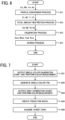
- FIG. 6 is a flowchart illustrating an example of image processing performed by the image processing apparatus 1 according to the first embodiment. The image processing performed by the image processing apparatus 1 according to this embodiment will be described with reference to FIG. 6 .
- the image processing unit 18 performs a profile conversion process. Namely, the image processing unit 18 converts an input device value (Cin, Min, Yin, Kin) of image data input from the image input unit 17 into an intermediate device value (C1, M1, Y1, K1) by using an International Color Consortium (ICC) profile. The process then proceeds to step S12.
- an input device value Cin, Min, Yin, Kin
- ICC International Color Consortium
- the image processing unit 18 performs a total amount restriction process. Namely, the image processing unit 18 replaces an intermediate device value exceeding a total amount value that can be output from the image forming apparatus 2 with an intermediate device value (C2, M2, Y2, K2). The intermediate device value (C2, M2, Y2, K2) is less than or equal to the total amount value. The process then proceeds to step S13.
- the image processing unit 18 performs a calibration process. Namely, the image processing unit 18 converts the intermediate device value (C2, M2, Y2, K2) into an output device value (Cout, Mout, Yout, Kout) by using the single-color TRC generated by the TRC generation unit 15. The process then proceeds to step S14.
- the image processing unit 18 performs a screen process. Namely, the image processing unit 18 converts the image data including the output device value (Cout, Mout, Yout, Kout) into halftone dot data to be used to output the image data from the image forming apparatus 2. Then, the image processing performed by the image processing apparatus 1 ends.
- the output device value Cout, Mout, Yout, Kout
- FIG. 7 is a flowchart illustrating an example of a target gray acquisition process of the image processing apparatus 1 according to the first embodiment.
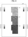
- FIG. 8 illustrates an example of a gray-correction chart in the first state according to the first embodiment.
- the target gray acquisition process of the image processing apparatus 1 according to this embodiment will be described with reference to FIGs. 7 and 8 .
- the target gray acquisition process of the image processing apparatus 1 is performed in the first state described above.
- the chart image generation unit 16 generates a single-color calibration chart.
- the image data of the single-color calibration chart is subjected to image processing by the image processing unit 18 and is output from the image output unit 19 to the image forming apparatus 2.
- the image processing unit 18 does not perform the profile conversion process or the calibration process. That is, the image data of the single-color calibration chart is output such that the input device value (Cin, Min, Yin, Kin) is equal to the output device value (Cout, Mout, Yout, Kout).
- the image forming apparatus 2 outputs the single-color calibration chart, and the colorimeter 4 performs a color measurement process. The process then proceeds to step S22.
- the colorimetric value acquisition unit 11 acquires the colorimetric values of the single-color calibration chart from the colorimeter 4.
- the target acquisition unit 13 acquires a target single color from the colorimetric values and stores the target single color in the storage unit 14.
- the TRC generation unit 15 generates a single-color TRC so as to match the target single color stored in the storage unit 14, and stores the single-color TRC in the storage unit 14. Since the result of the gray correction process described below is directly applied to the single-color TRC, the format of the values of the target single color and the method for generating the single-color TRC are not limited to a specific format and method. The process then proceeds to step S23.
- the chart image generation unit 16 generates, for example, a gray-correction chart 30 illustrated in FIG. 8 .
- the gray-correction chart 30 includes sets of patches 31 to 34 and patch groups 36 to 38. Each of the sets of patches 31 to 34 is arranged at a corresponding one of the four corners of the gray-correction chart 30.
- the patch group 36 is a group of patches of adjacent grays that are assigned in combinations of ⁇ 5% for C and M and ⁇ 10% for Y (an example of a second gradation value) relative to the dot area ratio of the patch 32.
- the patch group 37 is a group of patches of adjacent grays that are assigned in combinations of ⁇ 5% for C and M and ⁇ 10% for Y (an example of a second gradation value) relative to the dot area ratio of the patch 33.
- the patch group 38 is a group of patches of adjacent grays that are assigned in combinations of ⁇ 5% for C and M and ⁇ 10% for Y (an example of a second gradation value) relative to the dot area ratio of the patch 34.
- the patch groups 36 to 38 also include patches having the same dot area ratios as those of the patches 32 to 34, respectively.
- the sets of the patches 31 to 34 are not limited to being arranged at the four corners and may be arranged at positions at which the colorimetric values of the respective target grays are accurately obtained.
- the image data of the gray-correction chart 30 is subjected to image processing by the image processing unit 18 and is output from the image output unit 19 to the image forming apparatus 2.
- the image processing unit 18 performs the calibration process without performing the profile conversion process.
- the image forming apparatus 2 outputs the gray-correction chart 30, and the colorimeter 4 performs a color measurement process. The process then proceeds to step S24.
- the colorimetric value acquisition unit 11 acquires the colorimetric values of the gray-correction chart 30 from the colorimeter 4.
- the prediction model creation unit 12 acquires, from among the colorimetric values described above, each of the grays of the patch group 36, each of the grays of the patch group 37, and each of the grays of the patch group 38 as a 20% target-adjacent gray, a 40% target-adjacent gray, and a 60% target-adjacent gray, respectively.
- the 20% target-adjacent gray, the 40% target-adjacent gray, and the 60% target-adjacent gray are examples of a second colorimetric value.
- the prediction model creation unit 12 creates a prediction model from the 20% target-adjacent gray, for predicting a colorimetric value from a dot area ratio around 20%.
- This prediction model is hereinafter also referred to as a 20% prediction model.
- the prediction model creation unit 12 creates a 40% prediction model from the 40% target-adjacent gray, and creates a 60% prediction model from the 60% target-adjacent gray. That is, high-gradation prediction models, namely, the 20%, 40% and 60% prediction models, are created from the target-adjacent grays acquired in the first state. The process then proceeds to step S25.
- the target acquisition unit 13 acquires the colorimetric values of the patches 31 to 34 from among the colorimetric values acquired by the colorimetric value acquisition unit 11. Then, the target acquisition unit 13 calculates an average value of the colorimetric values of the patch 31 at the four positions to acquire a 10% target gray. The target acquisition unit 13 also calculates an average value of the colorimetric values of the patch 32 at the four positions to acquire a 20% target gray. The target acquisition unit 13 also calculates an average value of the colorimetric values of the patch 33 at the four positions to acquire a 40% target gray. The target acquisition unit 13 also calculates an average value of the colorimetric values of the patch 34 at the four positions to acquire a 60% target gray. The average values are examples of a first colorimetric value. Then, the target gray acquisition process of the image processing apparatus 1 ends.
- FIG. 9 is a flowchart illustrating an example of a gray correction process of the image processing apparatus 1 according to the first embodiment.
- FIG. 10 illustrates an example of a gray-correction chart in the second state according to the first embodiment.
- FIG. 11 is a flowchart illustrating an example of a gray correction value calculation process of the image processing apparatus 1 according to the first embodiment.
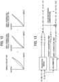
- FIG. 12 illustrates a gray-correction single-color TRC.
- FIG. 13 illustrates a process for calculating a gray correction value in the image processing apparatus 1 according to the first embodiment.
- the gray correction process of the image processing apparatus 1 according to this embodiment will be described with reference to FIGs. 9 to 13 .
- the gray correction process of the image processing apparatus 1 is performed in the second state described above.
- the chart image generation unit 16 generates a single-color calibration chart.
- the image data of the single-color calibration chart is subjected to image processing by the image processing unit 18 and is output from the image output unit 19 to the image forming apparatus 2.
- the image processing unit 18 does not perform the profile conversion process or the calibration process. That is, the image data of the single-color calibration chart is output such that the input device value (Cin, Min, Yin, Kin) is equal to the output device value (Cout, Mout, Yout, Kout).
- the image forming apparatus 2 outputs the single-color calibration chart, and the colorimeter 4 performs a color measurement process. The process then proceeds to step S32.
- the colorimetric value acquisition unit 11 acquires the colorimetric values of the single-color calibration chart from the colorimeter 4.
- the target acquisition unit 13 acquires a target single color from the colorimetric values and stores the target single color in the storage unit 14.
- the TRC generation unit 15 generates a single-color TRC so as to match the target single color stored in the storage unit 14, and updates the single-color TRC stored in the storage unit 14 with the generated single-color TRC. The process then proceeds to step S33.
- the chart image generation unit 16 generates, for example, a gray-correction chart 40 illustrated in FIG. 10 .
- the gray-correction chart 40 includes sets of patches 41 to 44 and a patch group 45. Each of the sets of patches 41 to 44 is arranged at a corresponding one of the four corners of the gray-correction chart 40.
- the patch group 45 is a group of patches of adjacent grays that are assigned in combinations of ⁇ 5% for C and M and ⁇ 10% for Y (an example of a second gradation value) relative to the dot area ratio of the patch 41.
- the patch group 45 also includes a patch having the same dot area ratio as that of the patch 41.
- the sets of the patches 41 to 44 are not limited to being arranged at the four corners and may be arranged at positions at which the colorimetric values of the respective pre-correction grays are accurately obtained.
- the image data of the gray-correction chart 40 is subjected to image processing by the image processing unit 18 and is output from the image output unit 19 to the image forming apparatus 2.
- the image processing unit 18 performs the calibration process by using the single-color TRC in step S32 without performing the profile conversion process.
- the image forming apparatus 2 outputs the gray-correction chart 40, and the colorimeter 4 performs a color measurement process. The process then proceeds to step S34.
- the colorimetric value acquisition unit 11 acquires the colorimetric values of the gray-correction chart 40 from the colorimeter 4.
- the prediction model creation unit 12 acquires, from among the colorimetric values described above, each of the grays of the patch group 45 as a 10% target-adjacent gray.
- the 10% target-adjacent gray is an example of a second colorimetric value.
- the prediction model creation unit 12 creates a prediction model from the 10% target-adjacent gray, for predicting a colorimetric value from a dot area ratio around 10%.
- This prediction model is hereinafter also referred to as a 10% prediction model. That is, a low-gradation prediction model, namely, the 10% prediction model, is created from a target-adjacent gray acquired in the second state.
- the process then proceeds to step S35.
- the TRC generation unit 15 acquires the colorimetric values of the patches 41 to 44 from among the colorimetric values acquired by the colorimetric value acquisition unit 11. Then, the TRC generation unit 15 calculates an average value of the colorimetric values of the patch 41 at the four positions to acquire a 10% pre-correction gray. The TRC generation unit 15 also calculates an average value of the colorimetric values of the patch 42 at the four positions to acquire a 20% pre-correction gray. The TRC generation unit 15 also calculates an average value of the colorimetric values of the patch 43 at the four positions to acquire a 40% pre-correction gray. The TRC generation unit 15 also calculates an average value of the colorimetric values of the patch 44 at the four positions to acquire a 60% pre-correction gray.
- the 10% pre-correction gray, the 20% pre-correction gray, the 40% pre-correction gray, and the 60% pre-correction gray are examples of a third colorimetric value.
- the TRC generation unit 15 acquires, for the dot area ratio of each pre-correction gray, a correction value so as to match the corresponding target gray by using the corresponding prediction model.
- the details of the gray correction value calculation process which is a process for calculating a correction value by using the TRC generation unit 15, will be described hereinafter with reference to FIGs. 11 to 13 .
- the TRC generation unit 15 identifies the dot area ratio (C, M, Y) of one of the target grays for calculating a correction value. The process then proceeds to step S352.
- the TRC generation unit 15 identifies the dot area ratio (Cn, Mn, Yn) of one target-adjacent gray among the dot area ratios of the target-adjacent grays corresponding to the identified dot area ratio of the target gray. The process then proceeds to step S353.
- the TRC generation unit 15 determines whether the identified dot area ratio (Cn, Mn, Yn) of the target-adjacent gray is equal to the dot area ratio of the 10% target-adjacent gray. If the identified dot area ratio (Cn, Mn, Yn) of the target-adjacent gray is equal to the dot area ratio of the 10% target-adjacent gray (step S353: Yes), the process proceeds to step S354.
- step S353 If the identified dot area ratio (Cn, Mn, Yn) of the target-adjacent gray is equal to the dot area ratio of any one of the target-adjacent grays other than the 10% target-adjacent gray (here, the 20%, 40%, or 60% target-adjacent gray) (step S353: No), the process proceeds to step S355.
- the TRC generation unit 15 calculates the predicted values (L1, a1, b1) from the identified dot area ratio (C, M, Y) of the target gray (here, the 10% target gray) by using the prediction model created in the first state (here, the 10% prediction model). Further, the TRC generation unit 15 calculates the predicted values (L2, a2, b2) from the identified dot area ratio (Cn, Mn, Yn) of the target-adjacent gray (here, the 10% target-adjacent gray) by using the prediction model created in the second state (here, the 10% prediction model). The process then proceeds to step S356.
- the TRC generation unit 15 calculates the predicted values (L1, a1, b1) from the identified dot area ratio (C, M, Y) of the target gray (here, the 20%, 40%, or 60% target gray) by using the prediction model created in the first state. Further, the TRC generation unit 15 calculates the predicted values (L2, a2, b2) from the identified dot area ratio (Cn, Mn, Yn) of the target-adjacent gray (here, the 20%, 40%, or 60% target-adjacent gray) by using the prediction model created in the second state. The process then proceeds to step S356.
- the process then proceeds to step S357.
- the TRC generation unit 15 calculates the color difference between the calculated predicted Lab values and the colorimetric values (Lt, at, bt) of the target gray corresponding to the identified dot area ratio of the target gray. The process then proceeds to step S358.
- the TRC generation unit 15 determines whether the calculated color difference is less than or equal to a predetermined threshold (first threshold). If the color difference is less than or equal to the threshold (step S358: Yes), the process proceeds to step S360. If the color difference exceeds the threshold (step S358: No), the process proceeds to step S359.
- first threshold a predetermined threshold
- the TRC generation unit 15 identifies the dot area ratio (Cn, Mn, Yn) of another target-adjacent gray different from the identified dot area ratio of the target-adjacent gray among the dot area ratios of the target-adjacent grays corresponding to the identified dot area ratio of the target gray. The process then returns to step S353.
- the TRC generation unit 15 acquires the identified dot area ratio of the target-adjacent gray as a correction value that takes into account the gray relative to the identified dot area ratio of the target gray. The process then proceeds to step S361.
- the TRC generation unit 15 determines whether correction values for the dot area ratios of all of the target grays have been acquired. If correction values for the dot area ratios of all of the target grays have not been acquired (step S361: No), the process proceeds to step S362. If correction values for the dot area ratios of all of the target grays have been acquired (step S361: Yes), the gray correction value calculation process ends, and then the process proceeds to step S36 in FIG. 9 .
- the TRC generation unit 15 identifies the dot area ratio (C, M, Y) of another target gray different from the identified dot area ratio of the target gray among all of the target grays. The process then returns to step S352.
- the TRC generation unit 15 reflects a correction based on the calculated correction values (the gray correction value conversion illustrated in FIG. 12 ) in the single-color TRC obtained in step S32 to generate a single-color TRC (gray-corrected single-color TRC). Then, the TRC generation unit 15 updates the single-color TRC stored in the storage unit 14 with the generated single-color TRC.
- the image processing unit 18 executes a calibration process by using the single-color TRC (gray-corrected single-color TRC) to perform gray correction on the input device value to obtain an output device value. Then, the gray correction process of the image processing apparatus 1 ends.
- the configuration of the image processing apparatus 1 according to this embodiment makes it possible to accurately correct color mixtures while keeping the load of a color measurement process low for each correction.
- a prediction model for the 10% target-adjacent gray is created at the gray correction time (i.e., the second state).
- a prediction model for a target-adjacent gray having another dot area ratio may be created at the gray correction time (i.e., the second state).
- a prediction model for the 20% target-adjacent gray which is approximately a low-gradation target-adjacent gray, may be created at the gray correction time (i.e., the second state).
- An image processing apparatus will be described focusing on differences from the image processing apparatus 1 according to the first embodiment.
- This embodiment describes an operation of updating a prediction model created at the target gray acquisition time (i.e., the first state). Specifically, a local variation difference between the target gray acquisition time (i.e., the first state) and the gray correction time (i.e., the second state) is evaluated such that a prediction model for a target-adjacent gray for which the local variation difference is greater than or equal to a predetermined threshold is updated with a prediction model created at the gray correction time.
- the general arrangement of an information processing system 100 according to this embodiment, and the hardware configurations of an image processing apparatus, namely, an image processing apparatus 1a described below, an image forming apparatus 2, and a user PC 3 according to this embodiment are similar to those described in the first embodiment.
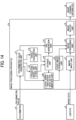
- FIG. 14 is a diagram illustrating an example configuration of functional blocks of the image processing apparatus 1a according to the second embodiment. The configuration and operation of the functional blocks of the image processing apparatus 1a according to this embodiment will be described with reference to FIG. 14 .
- the image processing apparatus 1a includes a colorimetric value acquisition unit 11, a prediction model creation unit 12 (second acquisition unit, creation unit), a target acquisition unit 13 (first acquisition unit), a storage unit 14, a TRC generation unit 15 (third acquisition unit, first calculation unit, first determination unit, fourth acquisition unit), a chart image generation unit 16, an image input unit 17, an image processing unit 18 (correction unit), an image output unit 19, and a local variation difference determination unit 20 (second calculation unit, second determination unit).
- the operations of the colorimetric value acquisition unit 11, the prediction model creation unit 12, the target acquisition unit 13, the storage unit 14, the TRC generation unit 15, the image input unit 17, the image processing unit 18, and the image output unit 19 are similar to those described in the first embodiment.
- the chart image generation unit 16 is a functional unit that generates a chart image.
- the chart image is used to acquire target grays, create prediction models, determine local variation differences, and perform a gray correction process.
- the local variation difference determination unit 20 is a functional unit that calculates a local variation difference from the colorimetric values acquired by the colorimetric value acquisition unit 11 and the prediction models stored in the storage unit 14 and performs threshold determination on the local variation difference.
- the local variation difference determination unit 20 is implemented by, for example, the CPU 501 illustrated in FIG. 2 executing a program.
- the colorimetric value acquisition unit 11, the prediction model creation unit 12, the target acquisition unit 13, the TRC generation unit 15, the chart image generation unit 16, the image input unit 17, the image processing unit 18, the image output unit 19, and the local variation difference determination unit 20 of the image processing apparatus 1a illustrated in FIG. 14 are not limited to being implemented by the CPU 501 illustrated in FIG. 2 executing a program.
- the colorimetric value acquisition unit 11, the prediction model creation unit 12, the target acquisition unit 13, the TRC generation unit 15, the chart image generation unit 16, the image input unit 17, the image processing unit 18, the image output unit 19, and the local variation difference determination unit 20 of the image processing apparatus 1a illustrated in FIG. 14 may be implemented by hardware such as integrated circuits or by a combination of software and hardware.
- the functional units of the image processing apparatus 1a illustrated in FIG. 14 are conceptually illustrated functions and are not limited to the illustrated components. For example, a plurality of functional units that are illustrated as independent functional units of the image processing apparatus 1a illustrated in FIG. 14 may be combined into one functional unit. Alternatively, a function of one of the functional units of the image processing apparatus 1a illustrated in FIG. 14 may be divided into a plurality of functions to form a plurality of functional units.
- FIG. 15 is a view illustrating an overview of a local variation difference calculation process of the image processing apparatus 1a according to the second embodiment. An overview of the local variation difference calculation process of the image processing apparatus 1a according to this embodiment will be described with reference to FIG. 15 .
- a color change (local variation) between the gradation of a target gray and the gradation of a gray adjacent to the target gray can be accurately corrected even by using a prediction model created at the target gray acquisition time (i.e., the first state) if the change (local variation difference) between the target gray acquisition time (i.e., the first state) and the gray correction time (i.e., the second state) is not large.
- the local variation may differ between the target gray acquisition time and the gray correction time due to a factor such as a change in the state of the image forming apparatus 2. For this reason, as illustrated in FIG.
- a correction value calculated by using a prediction model created at the target gray acquisition time i.e., the first state
- the colorimetric values of the corrected gray fail to match the predicted values of the corrected gray.
- a large local variation difference between the target gray acquisition time and the gray correction time leads to low correction accuracy.
- a prediction model created at the gray correction time i.e., the second state
- a prediction model created at the target gray acquisition time i.e., the first state
- FIG. 16 illustrates an example of a gray-correction chart in the first state according to the second embodiment.
- the target gray acquisition process of the image processing apparatus 1a according to this embodiment is performed in accordance with the flowchart illustrated in FIG. 7 described above. Differences from the target gray acquisition process described above will be mainly described.
- step S23 the chart image generation unit 16 generates, for example, a gray-correction chart 50 illustrated in FIG. 16 .
- the gray-correction chart 50 includes sets of patches 51 to 54 and patch groups 55 to 58. Each of the sets of patches 51 to 54 is arranged at a corresponding one of the four corners of the gray-correction chart 50.
- the patch group 55 is a group of patches of adjacent grays that are assigned in combinations of ⁇ 5% for C and M and ⁇ 10% for Y (an example of a second gradation value) relative to the dot area ratio of the patch 51.
- the patch group 56 is a group of patches of adjacent grays that are assigned in combinations of ⁇ 5% for C and M and ⁇ 10% for Y (an example of a second gradation value) relative to the dot area ratio of the patch 52.
- the patch group 57 is a group of patches of adjacent grays that are assigned in combinations of ⁇ 5% for C and M and ⁇ 10% for Y (an example of a second gradation value) relative to the dot area ratio of the patch 53.
- the patch group 58 is a group of patches of adjacent grays that are assigned in combinations of ⁇ 5% for C and M and ⁇ 10% for Y (an example of a second gradation value) relative to the dot area ratio of the patch 54.
- the patch groups 55 to 58 also include patches having the same dot area ratios as those of the patches 51 to 54, respectively.
- the sets of the patches 51 to 54 are not limited to being arranged at the four corners and may be arranged at positions at which the colorimetric values of the respective target grays are accurately obtained.
- the image data of the gray-correction chart 50 is subjected to image processing by the image processing unit 18 and is output from the image output unit 19 to the image forming apparatus 2.
- the image processing unit 18 performs the calibration process without performing the profile conversion process.
- the image forming apparatus 2 outputs the gray-correction chart 50, and the colorimeter 4 performs a color measurement process.
- step S24 the colorimetric value acquisition unit 11 acquires the colorimetric values of the gray-correction chart 50 from the colorimeter 4.
- the prediction model creation unit 12 acquires, from among the colorimetric values described above, each of the grays of the patch group 55, each of the grays of the patch group 56, each of the grays of the patch group 57, and each of the grays of the patch group 58 as a 10% target-adjacent gray, a 20% target-adjacent gray, a 40% target-adjacent gray, and a 60% target-adjacent gray, respectively.
- the 10% target-adjacent gray, the 20% target-adjacent gray, the 40% target-adjacent gray, and the 60% target-adjacent gray are examples of a second colorimetric value.
- the prediction model creation unit 12 creates a prediction model from the 10% target-adjacent gray, for predicting a colorimetric value from a dot area ratio around 10%.
- This prediction model is a 10% prediction model, and is an example of a first prediction model.
- the prediction model creation unit 12 creates a 20% prediction model from the 20% target-adjacent gray, creates a 40% prediction model from the 40% target-adjacent gray, and creates a 60% prediction model from the 60% target-adjacent gray.
- the 20% prediction model, the 40% prediction model, and the 60% prediction model are examples of a first prediction model.
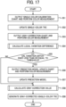
- FIG. 17 is a flowchart illustrating an example of a gray correction process of the image processing apparatus 1a according to the second embodiment.
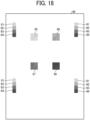
- FIG. 18 illustrates an example of a gray-correction chart in the second state according to the second embodiment.
- FIG. 19 illustrates an example of a prediction model update chart according to the second embodiment.
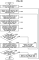
- FIG. 20 is a flowchart illustrating an example of the local variation difference calculation process of the image processing apparatus 1a according to the second embodiment.
- FIG. 21 illustrates a process for calculating a local variation difference in the image processing apparatus 1a according to the second embodiment.
- the gray correction process of the image processing apparatus 1a according to this embodiment will be described with reference to FIGs. 17 to 21 .
- the gray correction process of the image processing apparatus 1a is performed in the second state described above.
- the chart image generation unit 16 generates a single-color calibration chart.
- the image data of the single-color calibration chart is subjected to image processing by the image processing unit 18 and is output from the image output unit 19 to the image forming apparatus 2.
- the image processing unit 18 does not perform the profile conversion process or the calibration process. That is, the image data of the single-color calibration chart is output such that the input device value (Cin, Min, Yin, Kin) is equal to the output device value (Cout, Mout, Yout, Kout).
- the image forming apparatus 2 outputs the single-color calibration chart, and the colorimeter 4 performs a color measurement process. The process then proceeds to step S52.
- the colorimetric value acquisition unit 11 acquires the colorimetric values of the single-color calibration chart from the colorimeter 4.
- the target acquisition unit 13 acquires a target single color from the colorimetric values and stores the target single color in the storage unit 14.
- the TRC generation unit 15 generates a single-color TRC so as to match the target single color stored in the storage unit 14, and updates the single-color TRC stored in the storage unit 14 with the generated single-color TRC. The process then proceeds to step S53.
- the chart image generation unit 16 generates, for example, a gray-correction chart 60 illustrated in FIG. 18 .
- the gray-correction chart 60 includes sets of patches 61 to 64 and patch groups 65 to 68. Each of the sets of patches 61 to 64 is arranged at a corresponding one of the four corners of the gray-correction chart 60.
- the patch group 65 is a group of patches of adjacent grays that are assigned in any combination of ⁇ 5% for C and M and ⁇ 10% for Y (an example of a second gradation value) relative to the dot area ratio of the patch 61.
- the patch group 66 is a group of patches of adjacent grays that are assigned in any combination of ⁇ 5% for C and M and ⁇ 10% for Y (an example of a second gradation value) relative to the dot area ratio of the patch 62.
- the patch group 67 is a group of patches of adjacent grays that are assigned in any combination of ⁇ 5% for C and M and ⁇ 10% for Y (an example of a second gradation value) relative to the dot area ratio of the patch 63.
- the patch group 68 is a group of patches of adjacent grays that are assigned in any combination of ⁇ 5% for C and M and ⁇ 10% for Y (an example of a second gradation value) relative to the dot area ratio of the patch 64.
- the number of patches included in each of the patch groups 65 to 68 is smaller than the number of patches included in each of the patch groups 55 to 58 of the gray-correction chart 50 illustrated in FIG. 16 described above.
- the patch groups 65 to 68 also include patches having the same dot area ratios as those of the patches 61 to 64, respectively.
- the sets of the patches 61 to 64 are not limited to being arranged at the four corners and may be arranged at positions at which the colorimetric values of the respective pre-correction grays are accurately obtained.
- the image data of the gray-correction chart 60 is subjected to image processing by the image processing unit 18 and is output from the image output unit 19 to the image forming apparatus 2.
- the image processing unit 18 performs the calibration process by using the single-color TRC in step S52 without performing the profile conversion process.
- the image forming apparatus 2 outputs the gray-correction chart 60, and the colorimeter 4 performs a color measurement process. The process then proceeds to step S54.
- the local variation difference determination unit 20 calculates a local variation difference from the colorimetric values acquired by the colorimetric value acquisition unit 11, namely, the colorimetric values of the patches 61 to 64 and the colorimetric values of the patch groups 65 to 68, and from the 10%, 20%, 40%, and 60% prediction models stored in the storage unit 14. The details of the local variation difference calculation process of the local variation difference determination unit 20 will be described with reference to FIGs. 20 and 21 .
- the local variation difference determination unit 20 identifies the dot area ratio (C, M, Y) of one of the target grays for calculating a local variation difference. The process then proceeds to step S542.
- the local variation difference determination unit 20 identifies the dot area ratio (Cn, Mn, Yn) of one target-adjacent gray, which is acquired in the gray-correction chart 60 in step S53, among the dot area ratios of the target-adjacent grays corresponding to the identified dot area ratio of the target gray.
- the local variation difference determination unit 20 calculates the predicted values (L1, a1, b1) from the identified dot area ratio (C, M, Y) of the target gray by using the prediction model created in the first state. As illustrated in FIG. 21 , the local variation difference determination unit 20 further calculates the predicted values (L2, a2, b2) from the identified dot area ratio (Cn, Mn, Yn) of the target-adjacent gray by using the prediction model created in the first state. The process then proceeds to step S544.
- the local variation difference determination unit 20 acquires colorimetric values (Lt, at, bt) corresponding to the identified target gray and colorimetric values (Ln, an, bn) corresponding to the identified target-adjacent gray from among the colorimetric values acquired by the colorimetric value acquisition unit 11. The process then proceeds to step S545.
- the local variation difference determination unit 20 determines whether all of the local variation differences have been calculated for the target-adjacent grays corresponding to the identified target gray and acquired in the gray-correction chart 60 in step S53. If not all of the local variation differences for the target-adjacent grays have been calculated (step S546: No), the process proceeds to step S547. If all of the local variation differences for the target-adjacent grays have been calculated (step S546: Yes), the process proceeds to step S548.
- the local variation difference determination unit 20 identifies the dot area ratio (Cn, Mn, Yn) of another target-adjacent gray different from the identified dot area ratio of the target-adjacent gray among the dot area ratios of the target-adjacent grays corresponding to the identified dot area ratio of the target gray. The process then returns to step S543.
- the local variation difference determination unit 20 averages all the local variation differences for the target-adjacent grays corresponding to the identified dot area ratio of the target gray, and acquires the average as the local variation difference for the target gray. The process then proceeds to step S549.
- the local variation difference determination unit 20 determines whether the local variation differences for all of the target grays have been acquired. If the local variation differences for all of the target grays have not been acquired (step S549: No), the process proceeds to step S550. If the local variation differences for all of the target grays have been acquired (step S549: Yes), the local variation difference calculation process ends, and then the process proceeds to step S55 in FIG. 17 .
- the local variation difference determination unit 20 identifies the dot area ratio (C, M, Y) of another target gray different from the identified dot area ratio of the target gray among all of the target grays. The process then returns to step S542.
- the local variation difference determination unit 20 determines whether each the respective local variation difference calculated for the target grays is greater than or equal to a predetermined threshold (second threshold). If at least one of the local variation differences for the target grays is greater than or equal to the threshold (step S55: Yes), the process proceeds to step S56. If all of the local variation differences for the target grays are less than the threshold (step S55: No), the process proceeds to step S58.
- second threshold a predetermined threshold
- the chart image generation unit 16 generates a prediction model update chart 70 illustrated in FIG. 19 , for example.
- the prediction model update chart 70 includes a patch group for adjacent grays corresponding to a target gray for which the local variation difference is determined by the local variation difference determination unit 20 to be greater than or equal to the threshold.
- the local variation difference determination unit 20 determines that the local variation differences for the 10% target gray and the 60% target gray are greater than or equal to the threshold.
- the prediction model update chart 70 includes patch groups 75 and 78.
- the patch group 75 is a group of patches of adjacent grays that are assigned in combinations of ⁇ 5% for C and M and ⁇ 10% for Y (an example of a second gradation value) relative to the dot area ratio of the 10% target gray.
- the patch group 78 is a group of patches of adjacent grays that are assigned in combinations of ⁇ 5% for C and M and ⁇ 10% for Y (an example of a second gradation value) relative to the dot area ratio of the 60% target gray.
- the image data of the prediction model update chart 70 is subjected to image processing by the image processing unit 18 and is output from the image output unit 19 to the image forming apparatus 2.
- the image processing unit 18 performs the calibration process by using the single-color TRC in step S52 without performing the profile conversion process.
- the image forming apparatus 2 outputs the prediction model update chart 70, and the colorimeter 4 performs a color measurement process. The process then proceeds to step S57.
- the colorimetric value acquisition unit 11 acquires the colorimetric values of the prediction model update chart 70 from the colorimeter 4.
- the prediction model creation unit 12 acquires each of the grays of the patch group 75 from among the colorimetric values as a 10% target-adjacent gray, and creates a prediction model from the 10% target-adjacent gray, for predicting a colorimetric value from a dot area ratio around 10%.
- This prediction model is a 10% prediction model, and is an example of a second prediction model.
- the prediction model creation unit 12 further acquires each of the grays of the patch group 78 from among the colorimetric values as a 60% target-adjacent gray, and creates a prediction model from the 60% target-adjacent gray, for predicting a colorimetric value from a dot area ratio around 60%.
- This prediction model is a 60% prediction model, and is an example of a second prediction model. The process then proceeds to step S58.
- the TRC generation unit 15 acquires the colorimetric values of the patches 61 to 64 from among the colorimetric values acquired by the colorimetric value acquisition unit 11 for the gray-correction chart 60. Then, the TRC generation unit 15 calculates an average value of the colorimetric values of the patch 61 at the four positions to acquire a 10% pre-correction gray. The TRC generation unit 15 also calculates an average value of the colorimetric values of the patch 62 at the four positions to acquire a 20% pre-correction gray. The TRC generation unit 15 also calculates an average value of the colorimetric values of the patch 63 at the four positions to acquire a 40% pre-correction gray.
- the TRC generation unit 15 also calculates an average value of the colorimetric values of the patch 64 at the four positions to acquire a 60% pre-correction gray.
- the 10% pre-correction gray, the 20% pre-correction gray, the 40% pre-correction gray, and the 60% pre-correction gray are examples of a third colorimetric value.
- the TRC generation unit 15 acquires, for the dot area ratio of each pre-correction gray, a correction value so as to match the corresponding target gray by using the corresponding prediction model.
- the TRC generation unit 15 acquires correction values for the dot area ratios of the 20% pre-correction gray and the 40% pre-correction gray by using the prediction model created in the first state described above.
- the TRC generation unit 15 further acquires correction values for the dot area ratios of the 10% pre-correction gray and the 60% pre-correction gray by using the prediction model created in step S57 described above (i.e., the prediction model created in the second state).
- the gray correction value calculation process which is a process for calculating a correction value by using the TRC generation unit 15, is performed in accordance with the flowchart illustrated in FIG. 11 . The process then proceeds to step S59.
- the TRC generation unit 15 reflects a correction based on the calculated correction values in the single-color TRC obtained in step S52 to generate a single-color TRC (gray-corrected single-color TRC). Then, the TRC generation unit 15 updates the single-color TRC stored in the storage unit 14 with the generated single-color TRC. After that, the image processing unit 18 executes a calibration process by using the single-color TRC (gray-corrected single-color TRC) to perform gray correction on the input device value to obtain an output device value.
- the configuration of the image processing apparatus 1a makes it possible to accurately correct color mixtures while keeping the load of a color measurement process low for each correction.
- printing of a chart and color measurement are not performed more than necessary to create a prediction model at the gray correction time. This provides accurate gray correction while reducing the load of the color measurement on the user.
- circuitry or processing circuitry which includes general purpose processors, special purpose processors, integrated circuits, application specific integrated circuits (ASICs), digital signal processors (DSPs), field programmable gate arrays (FPGAs), conventional circuitry and/or combinations thereof which are configured or programmed to perform the disclosed functionality.
- Processors are considered processing circuitry or circuitry as they include transistors and other circuitry therein.
- the circuitry, units, or means are hardware that carry out or are programmed to perform the recited functionality.
- the hardware may be any hardware disclosed herein or otherwise known which is programmed or configured to carry out the recited functionality.
- the hardware is a processor which may be considered a type of circuitry
- the circuitry, means, or units are a combination of hardware and software, the software being used to configure the hardware and/or processor.
- the programs to be executed by the image processing apparatuses 1 and 1a according to the embodiments described above may be configured to be pre-installed in a ROM or the like and provided.
- the programs to be executed by the image processing apparatuses 1 and 1a according to the embodiments described above may be configured to be recorded in any computer-readable recording medium, such as a compact disc read only memory (CD-ROM), a flexible disk (FD), a CD-R, or a DVD, in an installable or executable file format and provided as a computer program product.
- CD-ROM compact disc read only memory
- FD flexible disk
- CD-R compact disc read only memory
- DVD digital versatile discs
- the programs to be executed by the image processing apparatuses 1 and 1a according to the embodiments described above may be configured to be stored in a computer connected to a network such as the Internet and provided by being downloaded via the network.
- the programs to be executed by the image processing apparatuses 1 and 1a according to the embodiments described above may be configured to be provided or distributed via a network such as the Internet.
- the programs to be executed by the image processing apparatuses 1 and 1a according to the embodiments described above have module configurations including the functional units described above.
- a CPU or processor
- the present invention can be implemented in any convenient form, for example using dedicated hardware, or a mixture of dedicated hardware and software.
- the present invention may be implemented as computer software implemented by one or more networked processing apparatuses.
- the processing apparatuses include any suitably programmed apparatuses such as a general purpose computer, a personal digital assistant, a Wireless Application Protocol (WAP) or third-generation (3G)-compliant mobile telephone, and so on. Since the present invention can be implemented as software, each and every aspect of the present invention thus encompasses computer software implementable on a programmable device.
- the computer software can be provided to the programmable device using any conventional carrier medium (carrier means).
- the carrier medium includes a transient carrier medium such as an electrical, optical, microwave, acoustic or radio frequency signal carrying the computer code.
- transient medium is a Transmission Control Protocol/Internet Protocol (TCP/IP) signal carrying computer code over an IP network, such as the Internet.
- the carrier medium may also include a storage medium for storing processor readable code such as a floppy disk, a hard disk, a compact disc read-only memory (CD-ROM), a magnetic tape device, or a solid state memory device.
Landscapes
- Engineering & Computer Science (AREA)
- Multimedia (AREA)
- Signal Processing (AREA)
- Image Processing (AREA)
- Color, Gradation (AREA)
- Facsimile Image Signal Circuits (AREA)
- Color Image Communication Systems (AREA)
Claims (7)
- Appareil de traitement d'image (1) pour effectuer une correspondance de couleur sur des gris composés de couleurs acquis sous deux états différents et ayant une valeur de dégradé cible identique, les deux états différents incluant un premier état et un deuxième état, l'appareil de traitement d'image comprenant :une première unité d'acquisition (11) configurée pour acquérir une première valeur colorimétrique d'au moins un mélange de couleurs cible, chaque mélange de couleurs cible consistant en un gris cible, à partir d'un nuancier imprimé par un appareil de formation d'image, sur la base d'une ou plusieurs premières valeurs de dégradé, sous le premier état, chaque mélange de couleurs cible correspondant à chacune des une ou plusieurs premières valeurs de dégradé ;une deuxième unité d'acquisition (11) configurée pour acquérir des deuxièmes valeurs colorimétriques de mélanges de couleurs adjacents, consistant en des gris adjacents au gris cible, pour des deuxièmes valeurs de dégradé adjacentes à des premières valeurs de dégradé ayant une valeur de dégradé élevée parmi les une ou plusieurs premières valeurs de dégradé, à partir du nuancier imprimé par l'appareil de formation d'image sous le premier état, et pour acquérir des deuxièmes valeurs colorimétriques de mélanges de couleurs adjacents pour des deuxièmes valeurs de dégradé adjacentes à une première valeur de dégradé restante autre que les premières valeurs de dégradé ayant une valeur de dégradé élevée parmi les une ou plusieurs premières valeurs de dégradé, à partir d'un nuancier imprimé par l'appareil de formation d'image sous le deuxième état, le deuxième état étant un état chronologiquement postérieur au premier état ;une troisième unité d'acquisition (11) configurée pour acquérir une troisième valeur colorimétrique d'au moins un mélange de couleurs de précorrection, consistant en un gris de précorrection, à partir d'un nuancier imprimé par l'appareil de formation d'image, sur la base de chacune des une ou plusieurs premières valeurs de dégradé, sous le deuxième état, chaque mélange de couleurs de précorrection correspondant à chacune des une ou plusieurs premières valeurs de dégradé ;une unité de création (12) configurée pour créer des modèles de prédiction respectifs correspondant aux une ou plusieurs premières valeurs de dégradé, pour prédire une valeur colorimétrique à partir d'une valeur de dégradé, les modèles de prédiction étant créés sur la base des deuxièmes valeurs de dégradé et des deuxièmes valeurs colorimétriques ;une première unité de calcul (15) configurée pour déterminer une différence entre une première valeur, prédite à partir de chacune des une ou plusieurs premières valeurs de dégradé en utilisant un modèle correspondant parmi les modèles de prédiction, et une deuxième valeur prédite à partir de l'une des deuxièmes valeurs de dégradé correspondant à la première valeur de dégradé en utilisant le modèle correspondant parmi lesdits modèles de prédiction, et pour ajouter la différence à la troisième valeur colorimétrique correspondant à la première valeur colorimétrique pour calculer une valeur colorimétrique prédite de chaque mélange de couleurs cible ;une première unité de détermination (15) configurée pour déterminer si une différence de couleur entre chaque valeur colorimétrique prédite et la première valeur colorimétrique correspondant à la valeur colorimétrique prédite est inférieure ou égale à un premier seuil ;une quatrième unité d'acquisition (15) configurée pour acquérir, comme valeur de correction, la deuxième valeur de dégradé à partir de laquelle la valeur colorimétrique prédite est calculée, en réponse au fait que la différence de couleur est inférieure ou égale au premier seuil ; etune unité de correction (18) configurée pour corriger une valeur correspondante parmi les une ou plusieurs premières valeurs de dégradé en utilisant la valeur de correction de telle façon qu'une valeur colorimétrique du mélange de couleurs de précorrection devienne égale à une valeur colorimétrique du mélange de couleurs cible.
- Appareil de traitement d'image selon la revendication 1,dans lequel la deuxième unité d'acquisition (11) est en outre configurée pour acquérir des deuxièmes valeurs colorimétriques respectives pour des deuxièmes valeurs de dégradé adjacentes à toutes des une ou plusieurs premières valeurs de dégradé, à partir du nuancier imprimé par l'appareil de formation d'image sous le premier état et du nuancier imprimé par l'appareil de formation d'image sous le deuxième état,ledit appareil de traitement d'image comprenant en outre :une deuxième unité de calcul (20) configurée pour calculer une différence de variation locale entre une première différence et une deuxième différence, la première différence étant une différence entre une valeur colorimétrique, prédite à partir de chacune des une ou plusieurs premières valeurs de dégradé en utilisant un modèle correspondant parmi les premiers modèles de prédiction, et une valeur colorimétrique prédite à partir d'une deuxième valeur de dégradé correspondant à la première valeur de dégradé parmi les deuxièmes valeurs de dégradé en utilisant le modèle correspondant parmi les premiers modèles de prédiction, la deuxième différence étant une différence entre la première valeur colorimétrique correspondant à la première valeur de dégradé sous le deuxième état et une valeur correspondante parmi les deuxièmes valeurs colorimétriques pour la deuxième valeur de dégradé correspondant à la première valeur de dégradé ; etune deuxième unité de détermination (20) configurée pour déterminer si la différence de variation locale est supérieure ou égale à un deuxième seuil ;ladite deuxième unité d'acquisition (11) étant configurée pour acquérir la deuxième valeur colorimétrique pour la deuxième valeur de dégradé adjacente à la première valeur de dégradé correspondant à la différence de variation locale, à partir du nuancier imprimé par l'appareil de formation d'image sous le deuxième état en réponse au fait que la différence de variation locale est supérieure ou égale au deuxième seuil,ladite unité de création (12) étant en outre configurée pour créer un deuxième modèle de prédiction, sur la base de la deuxième valeur colorimétrique acquise par la deuxième unité d'acquisition (11) en réponse au fait que la différence de variation locale est supérieure ou égale au deuxième seuil, le deuxième modèle de prédiction correspondant à la première valeur de dégradé correspondant à la deuxième valeur colorimétrique acquise, etladite première unité de calcul (15) étant configurée pour :déterminer, comme la différence, en réponse à la présence du deuxième modèle de prédiction correspondant à la première valeur de dégradé, une différence entre la première valeur colorimétrique, prédite à partir de la première valeur de dégradé en utilisant le deuxième modèle de prédiction, et la deuxième valeur colorimétrique prédite à partir de la deuxième valeur de dégradé correspondant à la première valeur de dégradé en utilisant le deuxième modèle de prédiction, etdéterminer, comme la différence, en réponse à l'absence du deuxième modèle de prédiction correspondant à la première valeur de dégradé, une différence entre la première valeur colorimétrique, prédite à partir de la première valeur de dégradé en utilisant un premier modèle de prédiction correspondant à la première valeur de dégradé parmi les premiers des modèles de prédiction, et la deuxième valeur colorimétrique prédite à partir de la deuxième valeur de dégradé correspondant à la première valeur de dégradé en utilisant le premier modèle de prédiction correspondant à la première valeur de dégradé.
- Appareil de traitement d'image selon la revendication 1 ou 2, dans lequel le mélange de couleurs cible, les mélanges de couleurs adjacents et le mélange de couleurs de précorrection sont chacun un mélange de cyan, magenta et jaune.
- Appareil de traitement d'image selon la revendication 1, 2 ou 3, dans lequel la première valeur colorimétrique, les deuxièmes valeurs colorimétriques et la troisième valeur colorimétrique sont chacune une valeur de couleur dans un espace colorimétrique L*a*b*.
- Système de traitement d'information comprenant :l'appareil de traitement d'image (1, 1a) selon l'une quelconque des revendications 1 à 4 ;l'appareil de formation d'image (2) ; etun colorimètre (4) configuré pour obtenir la première valeur colorimétrique, la deuxième valeur colorimétrique et la troisième valeur colorimétrique.
- Procédé de traitement d'image pour effectuer une correspondance de couleur sur des gris composés de couleurs acquis sous deux états différents et ayant une valeur de dégradé cible identique, les deux états différents incluant un premier état et un deuxième état, le procédé de traitement d'image comprenant les étapes consistant à :acquérir (S25) une première valeur colorimétrique d'au moins un mélange de couleurs cible, chaque mélange de couleurs cible consistant en un gris cible, à partir d'un nuancier imprimé par un appareil de formation d'image, sur la base d'une ou plusieurs premières valeurs de dégradé, sous le premier état, chaque mélange de couleurs cible correspondant à la ou à chacune des premières valeurs de dégradé ;acquérir (S24, S34) des deuxièmes valeurs colorimétriques de mélanges de couleurs adjacents, consistant en des gris adjacents au gris cible, pour des deuxièmes valeurs de dégradé adjacentes à des premières valeurs de dégradé ayant une valeur de dégradé élevée parmi les une ou plusieurs premières valeurs de dégradé, à partir du nuancier imprimé par l'appareil de formation d'image sous le premier état et acquérir des deuxièmes valeurs colorimétriques de mélanges de couleurs adjacents pour des deuxièmes valeurs de dégradé adjacentes à une première valeur de dégradé restante autre que les premières valeurs de dégradé ayant une valeur de dégradé élevée parmi les une ou plusieurs premières valeurs de dégradé, à partir d'un nuancier imprimé par l'appareil de formation d'image sous le deuxième état, le deuxième état étant un état chronologiquement postérieur au premier état ;acquérir (S35) une troisième valeur colorimétrique d'au moins un mélange de couleurs de précorrection, consistant en un gris de précorrection, à partir d'un nuancier imprimé par l'appareil de formation d'image, sur la base de chacune des une ou plusieurs premières valeurs de dégradé, sous le deuxième état, chaque mélange de couleurs de précorrection correspondant à chacune des une ou plusieurs premières valeurs de dégradé ;créer des modèles de prédiction respectifs correspondant aux une ou plusieurs premières valeurs de dégradé, pour prédire une valeur colorimétrique à partir d'une valeur de dégradé, les modèles de prédiction étant créés sur la base des deuxièmes valeurs de dégradé et des deuxièmes valeurs colorimétriques ;déterminer une différence entre une première valeur, prédite à partir de chacune des une ou plusieurs premières valeurs de dégradé en utilisant un modèle correspondant parmi les modèles de prédiction, et une deuxième valeur prédite à partir de l'une des deuxièmes valeurs de dégradé correspondant à la première valeur de dégradé en utilisant le modèle correspondant parmi lesdits modèles de prédiction, et ajouter (S356) la différence à la troisième valeur colorimétrique correspondant à la première valeur colorimétrique pour calculer une valeur colorimétrique prédite de chaque mélange de couleurs cible ;déterminer (S358) si une différence de couleur entre chaque valeur colorimétrique prédite et la première valeur colorimétrique correspondant à la valeur colorimétrique prédite est inférieure ou égale à un premier seuil ;acquérir (S360), comme valeur de correction, la deuxième valeur de dégradé à partir de laquelle la valeur colorimétrique prédite est calculée, en réponse au fait que la différence de couleur est inférieure ou égale au premier seuil ; etcorriger (S36) une valeur correspondante parmi les une ou plusieurs premières valeurs de dégradé en utilisant la valeur de correction de telle façon qu'une valeur colorimétrique du mélange de couleurs de précorrection devienne égale à une valeur colorimétrique du mélange de couleurs cible.
- Support lisible par ordinateur comprenant des instructions qui, lorsqu'elles sont exécutées par un ordinateur, amènent l'ordinateur à mettre en oeuvre le procédé de traitement d'image selon la revendication 6.
Applications Claiming Priority (1)
| Application Number | Priority Date | Filing Date | Title |
|---|---|---|---|
| JP2021171065A JP7743754B2 (ja) | 2021-10-19 | 2021-10-19 | 画像処理装置、情報処理システム、画像処理方法およびプログラム |
Publications (2)
| Publication Number | Publication Date |
|---|---|
| EP4171004A1 EP4171004A1 (fr) | 2023-04-26 |
| EP4171004B1 true EP4171004B1 (fr) | 2025-02-19 |
Family
ID=83457084
Family Applications (1)
| Application Number | Title | Priority Date | Filing Date |
|---|---|---|---|
| EP22197801.8A Active EP4171004B1 (fr) | 2021-10-19 | 2022-09-26 | Appareil de traitement d'image, système de traitement d'informations, procédé de traitement d'image et moyens de support |
Country Status (3)
| Country | Link |
|---|---|
| US (1) | US11831845B2 (fr) |
| EP (1) | EP4171004B1 (fr) |
| JP (1) | JP7743754B2 (fr) |
Families Citing this family (4)
| Publication number | Priority date | Publication date | Assignee | Title |
|---|---|---|---|---|
| JP7743754B2 (ja) * | 2021-10-19 | 2025-09-25 | 株式会社リコー | 画像処理装置、情報処理システム、画像処理方法およびプログラム |
| JP2025005280A (ja) * | 2023-06-27 | 2025-01-16 | 株式会社リコー | 画像処理装置、情報処理システム、画像処理方法およびプログラム |
| CN118196068B (zh) * | 2024-04-07 | 2024-10-01 | 浙江红绿蓝纺织印染有限公司 | 一种基于人工智能的纺织品印染质量监控系统 |
| JP2026013877A (ja) * | 2024-07-18 | 2026-01-29 | 株式会社リコー | 画像処理装置、情報処理システム、画像処理方法およびプログラム |
Family Cites Families (16)
| Publication number | Priority date | Publication date | Assignee | Title |
|---|---|---|---|---|
| JP4453820B2 (ja) | 2004-02-25 | 2010-04-21 | 富士ゼロックス株式会社 | キャリブレーション方法及びキャリブレーション装置 |
| JP2007174125A (ja) | 2005-12-20 | 2007-07-05 | Canon Inc | グレイ調整方法及び記録システム |
| JP4293200B2 (ja) | 2006-04-06 | 2009-07-08 | コニカミノルタビジネステクノロジーズ株式会社 | 画像形成装置及び画像形成方法 |
| JP4751853B2 (ja) * | 2007-05-15 | 2011-08-17 | 株式会社リコー | グレーバランス調整プログラム、記録媒体及びグレーバランス調整方法 |
| JP4666069B2 (ja) * | 2008-02-18 | 2011-04-06 | 富士ゼロックス株式会社 | 色補正係数生成装置及びプログラム |
| JP5142890B2 (ja) * | 2008-08-27 | 2013-02-13 | キヤノン株式会社 | 画像処理方法及び画像処理装置 |
| JP5617567B2 (ja) * | 2010-11-30 | 2014-11-05 | コニカミノルタ株式会社 | キャリブレーションシステム、キャリブレーション方法及びプログラム |
| JP2013143573A (ja) | 2012-01-06 | 2013-07-22 | Ricoh Co Ltd | 画像処理装置、画像処理方法、プログラムおよび記録媒体 |
| US8934156B2 (en) * | 2012-01-06 | 2015-01-13 | Ricoh Company, Ltd. | Image processing apparatus, image processing method, program, and recording medium |
| JP2016100637A (ja) * | 2014-11-18 | 2016-05-30 | キヤノン株式会社 | 画像形成装置、画像処理方法、およびプログラム |
| JP6191922B2 (ja) | 2015-02-17 | 2017-09-06 | コニカミノルタ株式会社 | 色精度検証予測方法及び制御装置並びに色精度検証予測プログラム |
| JP7268303B2 (ja) | 2018-08-24 | 2023-05-08 | コニカミノルタ株式会社 | 色精度検証装置、色精度検証方法及びプログラム |
| JP7183893B2 (ja) * | 2019-03-20 | 2022-12-06 | 株式会社リコー | 画像形成装置および画像形成ユニット |
| US11323592B2 (en) * | 2019-07-11 | 2022-05-03 | Ricoh Company, Ltd. | Image processing reducing processing time of tone correction calibration with fluorescent or special colors by selection of color combinations |
| JP2021150803A (ja) * | 2020-03-18 | 2021-09-27 | 株式会社リコー | 情報処理装置、表示装置及びプログラム |
| JP7743754B2 (ja) * | 2021-10-19 | 2025-09-25 | 株式会社リコー | 画像処理装置、情報処理システム、画像処理方法およびプログラム |
-
2021
- 2021-10-19 JP JP2021171065A patent/JP7743754B2/ja active Active
-
2022
- 2022-09-23 US US17/951,372 patent/US11831845B2/en active Active
- 2022-09-26 EP EP22197801.8A patent/EP4171004B1/fr active Active
Also Published As
| Publication number | Publication date |
|---|---|
| US20230120180A1 (en) | 2023-04-20 |
| JP2023061208A (ja) | 2023-05-01 |
| JP7743754B2 (ja) | 2025-09-25 |
| EP4171004A1 (fr) | 2023-04-26 |
| US11831845B2 (en) | 2023-11-28 |
Similar Documents
| Publication | Publication Date | Title |
|---|---|---|
| EP4171004B1 (fr) | Appareil de traitement d'image, système de traitement d'informations, procédé de traitement d'image et moyens de support | |
| JP5475402B2 (ja) | 画像処理装置、画像処理方法及びプログラム | |
| US20100328688A1 (en) | Image processing apparatus, image forming system, image processing method and computer readable medium | |
| JP5617567B2 (ja) | キャリブレーションシステム、キャリブレーション方法及びプログラム | |
| JP4766691B2 (ja) | 階調補正テーブル作成方法及び装置 | |
| JP7425969B2 (ja) | 画像形成装置 | |
| JP6623765B2 (ja) | 制御装置及び多次元補正方法並びに多次元補正プログラム | |
| US20080198392A1 (en) | Image Forming Apparatus and Calibration Method | |
| JP5107208B2 (ja) | 画像処理装置、画像処理方法、プログラムおよび記録媒体 | |
| US10917542B2 (en) | Color conversion information generation method, non-transitory computer-readable storage medium storing color conversion information generation program, and color conversion information generation apparatus | |
| JP2000190572A (ja) | 画像処理方法およびプリントシステム | |
| JP2010066502A (ja) | 画像形成装置及びプログラム | |
| EP4485916A1 (fr) | Appareil de traitement d'image, système de traitement d'informations, procédé de traitement d'image et support de support | |
| EP4683313A1 (fr) | Appareil de traitement d'image, système de traitement d'informations, procédé de traitement d'image et moyens de support | |
| JP3910323B2 (ja) | プロファイル作成方法およびプロファイル作成装置 | |
| JP2005210225A (ja) | 画像処理装置及び画像処理方法 | |
| JP7614854B2 (ja) | 画像処理装置、画像処理方法及びプログラム | |
| US20240393988A1 (en) | Processing apparatus, color management method, non-transitory recording medium, and image forming system | |
| JP2011151491A (ja) | 色変換装置及び色変換プログラム | |
| JP2010141701A (ja) | 画像処理システム、画像処理方法、プログラムおよび記録媒体 | |
| JP2025146366A (ja) | 画像処理装置、画像処理方法、およびプログラム | |
| JP2001245171A (ja) | 階調補正曲線作成方法、階調補正曲線作成装置、および階調補正曲線作成プログラム記憶媒体 | |
| JP4793364B2 (ja) | 色処理装置、画像形成装置及びプログラム | |
| JP2004112342A (ja) | 画像処理方法及び画像処理装置 | |
| JP2003348364A (ja) | 情報処理装置、出力装置、及び、色管理システム |
Legal Events
| Date | Code | Title | Description |
|---|---|---|---|
| PUAI | Public reference made under article 153(3) epc to a published international application that has entered the european phase |
Free format text: ORIGINAL CODE: 0009012 |
|
| STAA | Information on the status of an ep patent application or granted ep patent |
Free format text: STATUS: REQUEST FOR EXAMINATION WAS MADE |
|
| 17P | Request for examination filed |
Effective date: 20220926 |
|
| AK | Designated contracting states |
Kind code of ref document: A1 Designated state(s): AL AT BE BG CH CY CZ DE DK EE ES FI FR GB GR HR HU IE IS IT LI LT LU LV MC MK MT NL NO PL PT RO RS SE SI SK SM TR |
|
| GRAP | Despatch of communication of intention to grant a patent |
Free format text: ORIGINAL CODE: EPIDOSNIGR1 |
|
| STAA | Information on the status of an ep patent application or granted ep patent |
Free format text: STATUS: GRANT OF PATENT IS INTENDED |
|
| RIC1 | Information provided on ipc code assigned before grant |
Ipc: H04N 1/60 20060101AFI20240326BHEP |
|
| INTG | Intention to grant announced |
Effective date: 20240415 |
|
| RIN1 | Information on inventor provided before grant (corrected) |
Inventor name: MORIWAKI, ATSUSHI |
|
| P01 | Opt-out of the competence of the unified patent court (upc) registered |
Free format text: CASE NUMBER: APP_37079/2024 Effective date: 20240620 |
|
| GRAJ | Information related to disapproval of communication of intention to grant by the applicant or resumption of examination proceedings by the epo deleted |
Free format text: ORIGINAL CODE: EPIDOSDIGR1 |
|
| STAA | Information on the status of an ep patent application or granted ep patent |
Free format text: STATUS: REQUEST FOR EXAMINATION WAS MADE |
|
| GRAP | Despatch of communication of intention to grant a patent |
Free format text: ORIGINAL CODE: EPIDOSNIGR1 |
|
| GRAJ | Information related to disapproval of communication of intention to grant by the applicant or resumption of examination proceedings by the epo deleted |
Free format text: ORIGINAL CODE: EPIDOSDIGR1 |
|
| INTC | Intention to grant announced (deleted) | ||
| GRAP | Despatch of communication of intention to grant a patent |
Free format text: ORIGINAL CODE: EPIDOSNIGR1 |
|
| STAA | Information on the status of an ep patent application or granted ep patent |
Free format text: STATUS: GRANT OF PATENT IS INTENDED |
|
| INTG | Intention to grant announced |
Effective date: 20240923 |
|
| GRAS | Grant fee paid |
Free format text: ORIGINAL CODE: EPIDOSNIGR3 |
|
| GRAA | (expected) grant |
Free format text: ORIGINAL CODE: 0009210 |
|
| STAA | Information on the status of an ep patent application or granted ep patent |
Free format text: STATUS: THE PATENT HAS BEEN GRANTED |
|
| AK | Designated contracting states |
Kind code of ref document: B1 Designated state(s): AL AT BE BG CH CY CZ DE DK EE ES FI FR GB GR HR HU IE IS IT LI LT LU LV MC MK MT NL NO PL PT RO RS SE SI SK SM TR |
|
| REG | Reference to a national code |
Ref country code: GB Ref legal event code: FG4D |
|
| REG | Reference to a national code |
Ref country code: CH Ref legal event code: EP |
|
| REG | Reference to a national code |
Ref country code: IE Ref legal event code: FG4D |
|
| REG | Reference to a national code |
Ref country code: DE Ref legal event code: R096 Ref document number: 602022010751 Country of ref document: DE |
|
| REG | Reference to a national code |
Ref country code: NL Ref legal event code: MP Effective date: 20250219 |
|
| PG25 | Lapsed in a contracting state [announced via postgrant information from national office to epo] |
Ref country code: RS Free format text: LAPSE BECAUSE OF FAILURE TO SUBMIT A TRANSLATION OF THE DESCRIPTION OR TO PAY THE FEE WITHIN THE PRESCRIBED TIME-LIMIT Effective date: 20250519 |
|
| PG25 | Lapsed in a contracting state [announced via postgrant information from national office to epo] |
Ref country code: FI Free format text: LAPSE BECAUSE OF FAILURE TO SUBMIT A TRANSLATION OF THE DESCRIPTION OR TO PAY THE FEE WITHIN THE PRESCRIBED TIME-LIMIT Effective date: 20250219 |
|
| PG25 | Lapsed in a contracting state [announced via postgrant information from national office to epo] |
Ref country code: PL Free format text: LAPSE BECAUSE OF FAILURE TO SUBMIT A TRANSLATION OF THE DESCRIPTION OR TO PAY THE FEE WITHIN THE PRESCRIBED TIME-LIMIT Effective date: 20250219 |
|
| PG25 | Lapsed in a contracting state [announced via postgrant information from national office to epo] |
Ref country code: ES Free format text: LAPSE BECAUSE OF FAILURE TO SUBMIT A TRANSLATION OF THE DESCRIPTION OR TO PAY THE FEE WITHIN THE PRESCRIBED TIME-LIMIT Effective date: 20250219 |
|
| REG | Reference to a national code |
Ref country code: LT Ref legal event code: MG9D |
|
| PG25 | Lapsed in a contracting state [announced via postgrant information from national office to epo] |
Ref country code: IS Free format text: LAPSE BECAUSE OF FAILURE TO SUBMIT A TRANSLATION OF THE DESCRIPTION OR TO PAY THE FEE WITHIN THE PRESCRIBED TIME-LIMIT Effective date: 20250619 Ref country code: NO Free format text: LAPSE BECAUSE OF FAILURE TO SUBMIT A TRANSLATION OF THE DESCRIPTION OR TO PAY THE FEE WITHIN THE PRESCRIBED TIME-LIMIT Effective date: 20250519 |
|
| PG25 | Lapsed in a contracting state [announced via postgrant information from national office to epo] |
Ref country code: NL Free format text: LAPSE BECAUSE OF FAILURE TO SUBMIT A TRANSLATION OF THE DESCRIPTION OR TO PAY THE FEE WITHIN THE PRESCRIBED TIME-LIMIT Effective date: 20250219 |
|
| PG25 | Lapsed in a contracting state [announced via postgrant information from national office to epo] |
Ref country code: HR Free format text: LAPSE BECAUSE OF FAILURE TO SUBMIT A TRANSLATION OF THE DESCRIPTION OR TO PAY THE FEE WITHIN THE PRESCRIBED TIME-LIMIT Effective date: 20250219 |
|
| PG25 | Lapsed in a contracting state [announced via postgrant information from national office to epo] |
Ref country code: LV Free format text: LAPSE BECAUSE OF FAILURE TO SUBMIT A TRANSLATION OF THE DESCRIPTION OR TO PAY THE FEE WITHIN THE PRESCRIBED TIME-LIMIT Effective date: 20250219 Ref country code: PT Free format text: LAPSE BECAUSE OF FAILURE TO SUBMIT A TRANSLATION OF THE DESCRIPTION OR TO PAY THE FEE WITHIN THE PRESCRIBED TIME-LIMIT Effective date: 20250620 |
|
| PG25 | Lapsed in a contracting state [announced via postgrant information from national office to epo] |
Ref country code: BG Free format text: LAPSE BECAUSE OF FAILURE TO SUBMIT A TRANSLATION OF THE DESCRIPTION OR TO PAY THE FEE WITHIN THE PRESCRIBED TIME-LIMIT Effective date: 20250219 Ref country code: GR Free format text: LAPSE BECAUSE OF FAILURE TO SUBMIT A TRANSLATION OF THE DESCRIPTION OR TO PAY THE FEE WITHIN THE PRESCRIBED TIME-LIMIT Effective date: 20250520 |
|
| REG | Reference to a national code |
Ref country code: AT Ref legal event code: MK05 Ref document number: 1769477 Country of ref document: AT Kind code of ref document: T Effective date: 20250219 |
|
| PG25 | Lapsed in a contracting state [announced via postgrant information from national office to epo] |
Ref country code: SE Free format text: LAPSE BECAUSE OF FAILURE TO SUBMIT A TRANSLATION OF THE DESCRIPTION OR TO PAY THE FEE WITHIN THE PRESCRIBED TIME-LIMIT Effective date: 20250219 |
|
| PG25 | Lapsed in a contracting state [announced via postgrant information from national office to epo] |
Ref country code: SM Free format text: LAPSE BECAUSE OF FAILURE TO SUBMIT A TRANSLATION OF THE DESCRIPTION OR TO PAY THE FEE WITHIN THE PRESCRIBED TIME-LIMIT Effective date: 20250219 |
|
| PG25 | Lapsed in a contracting state [announced via postgrant information from national office to epo] |
Ref country code: DK Free format text: LAPSE BECAUSE OF FAILURE TO SUBMIT A TRANSLATION OF THE DESCRIPTION OR TO PAY THE FEE WITHIN THE PRESCRIBED TIME-LIMIT Effective date: 20250219 |
|
| PGFP | Annual fee paid to national office [announced via postgrant information from national office to epo] |
Ref country code: DE Payment date: 20250919 Year of fee payment: 4 |
|
| PG25 | Lapsed in a contracting state [announced via postgrant information from national office to epo] |
Ref country code: IT Free format text: LAPSE BECAUSE OF FAILURE TO SUBMIT A TRANSLATION OF THE DESCRIPTION OR TO PAY THE FEE WITHIN THE PRESCRIBED TIME-LIMIT Effective date: 20250219 |
|
| PG25 | Lapsed in a contracting state [announced via postgrant information from national office to epo] |
Ref country code: AT Free format text: LAPSE BECAUSE OF FAILURE TO SUBMIT A TRANSLATION OF THE DESCRIPTION OR TO PAY THE FEE WITHIN THE PRESCRIBED TIME-LIMIT Effective date: 20250219 |
|
| PGFP | Annual fee paid to national office [announced via postgrant information from national office to epo] |
Ref country code: FR Payment date: 20250922 Year of fee payment: 4 |
|
| PG25 | Lapsed in a contracting state [announced via postgrant information from national office to epo] |
Ref country code: EE Free format text: LAPSE BECAUSE OF FAILURE TO SUBMIT A TRANSLATION OF THE DESCRIPTION OR TO PAY THE FEE WITHIN THE PRESCRIBED TIME-LIMIT Effective date: 20250219 Ref country code: CZ Free format text: LAPSE BECAUSE OF FAILURE TO SUBMIT A TRANSLATION OF THE DESCRIPTION OR TO PAY THE FEE WITHIN THE PRESCRIBED TIME-LIMIT Effective date: 20250219 |
|
| PG25 | Lapsed in a contracting state [announced via postgrant information from national office to epo] |
Ref country code: RO Free format text: LAPSE BECAUSE OF FAILURE TO SUBMIT A TRANSLATION OF THE DESCRIPTION OR TO PAY THE FEE WITHIN THE PRESCRIBED TIME-LIMIT Effective date: 20250219 |
|
| PG25 | Lapsed in a contracting state [announced via postgrant information from national office to epo] |
Ref country code: SK Free format text: LAPSE BECAUSE OF FAILURE TO SUBMIT A TRANSLATION OF THE DESCRIPTION OR TO PAY THE FEE WITHIN THE PRESCRIBED TIME-LIMIT Effective date: 20250219 |
|
| REG | Reference to a national code |
Ref country code: DE Ref legal event code: R097 Ref document number: 602022010751 Country of ref document: DE |
|
| PLBE | No opposition filed within time limit |
Free format text: ORIGINAL CODE: 0009261 |
|
| STAA | Information on the status of an ep patent application or granted ep patent |
Free format text: STATUS: NO OPPOSITION FILED WITHIN TIME LIMIT |
|
| 26N | No opposition filed |
Effective date: 20251120 |