EP4171093A1 - Ressourcenkonfigurationsverfahren und -vorrichtung - Google Patents
Ressourcenkonfigurationsverfahren und -vorrichtung Download PDFInfo
- Publication number
- EP4171093A1 EP4171093A1 EP21831881.4A EP21831881A EP4171093A1 EP 4171093 A1 EP4171093 A1 EP 4171093A1 EP 21831881 A EP21831881 A EP 21831881A EP 4171093 A1 EP4171093 A1 EP 4171093A1
- Authority
- EP
- European Patent Office
- Prior art keywords
- cell
- frequency domain
- domain resource
- terminal device
- access network
- Prior art date
- Legal status (The legal status is an assumption and is not a legal conclusion. Google has not performed a legal analysis and makes no representation as to the accuracy of the status listed.)
- Pending
Links
Images




Classifications
-
- H—ELECTRICITY
- H04—ELECTRIC COMMUNICATION TECHNIQUE
- H04W—WIRELESS COMMUNICATION NETWORKS
- H04W16/00—Network planning, e.g. coverage or traffic planning tools; Network deployment, e.g. resource partitioning or cells structures
- H04W16/14—Spectrum sharing arrangements between different networks
-
- H—ELECTRICITY
- H04—ELECTRIC COMMUNICATION TECHNIQUE
- H04W—WIRELESS COMMUNICATION NETWORKS
- H04W72/00—Local resource management
- H04W72/04—Wireless resource allocation
- H04W72/044—Wireless resource allocation based on the type of the allocated resource
- H04W72/0453—Resources in frequency domain, e.g. a carrier in FDMA
-
- H—ELECTRICITY
- H04—ELECTRIC COMMUNICATION TECHNIQUE
- H04L—TRANSMISSION OF DIGITAL INFORMATION, e.g. TELEGRAPHIC COMMUNICATION
- H04L1/00—Arrangements for detecting or preventing errors in the information received
- H04L1/004—Arrangements for detecting or preventing errors in the information received by using forward error control
- H04L1/0056—Systems characterized by the type of code used
- H04L1/0067—Rate matching
-
- H—ELECTRICITY
- H04—ELECTRIC COMMUNICATION TECHNIQUE
- H04L—TRANSMISSION OF DIGITAL INFORMATION, e.g. TELEGRAPHIC COMMUNICATION
- H04L5/00—Arrangements affording multiple use of the transmission path
- H04L5/003—Arrangements for allocating sub-channels of the transmission path
- H04L5/0048—Allocation of pilot signals, i.e. of signals known to the receiver
- H04L5/0051—Allocation of pilot signals, i.e. of signals known to the receiver of dedicated pilots, i.e. pilots destined for a single user or terminal
-
- H—ELECTRICITY
- H04—ELECTRIC COMMUNICATION TECHNIQUE
- H04L—TRANSMISSION OF DIGITAL INFORMATION, e.g. TELEGRAPHIC COMMUNICATION
- H04L5/00—Arrangements affording multiple use of the transmission path
- H04L5/003—Arrangements for allocating sub-channels of the transmission path
- H04L5/0053—Allocation of signalling, i.e. of overhead other than pilot signals
-
- H—ELECTRICITY
- H04—ELECTRIC COMMUNICATION TECHNIQUE
- H04W—WIRELESS COMMUNICATION NETWORKS
- H04W72/00—Local resource management
- H04W72/50—Allocation or scheduling criteria for wireless resources
- H04W72/53—Allocation or scheduling criteria for wireless resources based on regulatory allocation policies
-
- H—ELECTRICITY
- H04—ELECTRIC COMMUNICATION TECHNIQUE
- H04W—WIRELESS COMMUNICATION NETWORKS
- H04W72/00—Local resource management
- H04W72/50—Allocation or scheduling criteria for wireless resources
- H04W72/54—Allocation or scheduling criteria for wireless resources based on quality criteria
-
- H—ELECTRICITY
- H04—ELECTRIC COMMUNICATION TECHNIQUE
- H04W—WIRELESS COMMUNICATION NETWORKS
- H04W56/00—Synchronisation arrangements
- H04W56/001—Synchronization between nodes
- H04W56/0015—Synchronization between nodes one node acting as a reference for the others
-
- H—ELECTRICITY
- H04—ELECTRIC COMMUNICATION TECHNIQUE
- H04W—WIRELESS COMMUNICATION NETWORKS
- H04W72/00—Local resource management
- H04W72/20—Control channels or signalling for resource management
- H04W72/23—Control channels or signalling for resource management in the downlink direction of a wireless link, i.e. towards a terminal
Definitions
- Embodiments of this application relate to the field of communication technologies, and in particular, to a resource configuration method and an apparatus.
- a 4G and 5G spectrum sharing technology has been launched in the industry.
- This technology enables a same spectrum to serve both a long term evolution (long term evolution, LTE) air interface technology of 4G and a new radio (new radio, NR) technology of 5G.
- LTE long term evolution
- NR new radio
- LTE and NR spectrum sharing based on this technology is usually implemented on a same carrier bandwidth of LTE and NR, that is, spectrum sharing is implemented by using LTE and NR.
- a difference between the LTE air interface technology and the NR new radio technology lies in the following:
- a cell reference signal (cell reference signal, CRS) is used by a terminal device to measure coverage strength of a cell, and is used by the terminal device to perform channel estimation, so as to demodulate received data.
- CRS cell reference signal
- a terminal device directly measures a synchronization signal and physical broadcast channel block (synchronization signal and physical broadcast channel block, SSB) to measure coverage strength of a cell, and then a separate user-level demodulation reference signal (demodulation reference signal, DMRS) is introduced to perform channel estimation during demodulation of received data.
- a synchronization signal and physical broadcast channel block synchronization signal and physical broadcast channel block, SSB
- a separate user-level demodulation reference signal demodulation reference signal
- this difference between LTE and NR causes a resource conflict.
- an NR cell needs to avoid resources for a CRS of an LTE cell, which reduces resource utilization of the NR cell.
- the LTE cell also needs to avoid resources for an SSB of the NR cell; otherwise, the terminal device in the NR cell cannot measure the NR cell.
- the terminal device in the LTE cell is usually a legacy terminal.
- Embodiments of this application provide a resource configuration method and apparatus, to resolve a problem that demodulation performance of a terminal device in an LTE cell deteriorates when resources for the LTE cell avoid resources for an NR cell.
- a resource configuration method including: obtaining, by an access network device, first configuration information, where the first configuration information includes a bandwidth range of a new radio NR cell, and the bandwidth range of the NR cell includes a dedicated frequency domain resource of the NR cell and a frequency domain resource shared by the NR cell and a long term evolution LTE cell; and sending, by the access network device, the first configuration information to a terminal device in the NR cell.
- the access network device may be a BBU.
- the dedicated frequency domain resource of the NR cell is configured, so that a signal allocating a resource in the dedicated frequency domain resource of the NR cell is not interfered with by the LTE cell during sending, and correspondingly, the signal allocating a resource in the dedicated frequency domain resource of the NR cell does not interfere with sending of a signal in the LTE cell during sending. Therefore, in this application, the dedicated frequency domain resource is configured for the NR cell, to avoid a problem that demodulation performance of the terminal device in the LTE cell deteriorates when resources for the LTE cell avoid resources for the NR cell. In addition, when receiving a signal on the dedicated frequency domain resource, the terminal device in the NR cell does not need to receive a rate matching template sent by an access device, to avoid sending of a signal in the LTE cell.
- the method further includes: obtaining, by the access network device, second configuration information, where the second configuration information includes a bandwidth range of the LTE cell, and the bandwidth range of the LTE cell includes the frequency domain resource shared by the LTE cell and the NR cell; and sending, by the access network device, the second configuration information to a terminal device in the LTE cell.
- the NR cell further has the dedicated frequency domain resource, it may be understood that the bandwidth range of the NR cell is greater than the bandwidth range of the LTE cell, and an extra bandwidth in the bandwidth range of the NR cell compared with the bandwidth range of the LTE cell is the dedicated frequency domain resource of the NR cell.
- the LTE cell may also have a dedicated frequency domain resource. Therefore, the dedicated frequency domain resource of the NR cell does not need to avoid the resources for the LTE cell, so that the demodulation performance of the terminal device in the LTE cell can be improved.
- the first configuration information is carried in a first system message
- the second configuration information is carried in a second system message. That is, the first configuration information may be periodically broadcast by the access network device to a terminal device within a range of the NR cell by using the first system message, so that the terminal device entering the range of the NR cell learns, in a timely manner, the bandwidth range configured by the access network device.
- the second configuration information is also periodically broadcast by the access network device to a terminal device within a range of the LTE cell by using the second system message, so that the terminal device entering the range of the LTE cell learns, in a timely manner, the bandwidth range configured by the access network device.
- the method further includes: allocating, by the access network device, a frequency domain resource to a first signal in the NR cell, where the frequency domain resource of the first signal is on the dedicated frequency domain resource; and the first signal includes at least one of the following signals: a signal used by the terminal device to synchronize with the access network device, a signal used by the terminal device to perform a timing function with the access network device, a signal used by the terminal device to obtain cell channel state information, a signal used by the terminal device to determine a cell to be camped on, and a signal used by the terminal device to access the access network device.
- the access network device may allocate, on the dedicated frequency domain resource of the NR cell, frequency domain resources to some relatively important signals that are prone to interference and affect access of the terminal device, and record these signals as the first signal.
- the BBU may allocate the resource on the dedicated frequency domain resource of the NR cell.
- the signal used by the terminal device to synchronize with the access network device includes a synchronization signal and physical broadcast channel block SSB; the signal used by the terminal device to perform a timing function with the access network device includes a tracking reference signal TRS; the signal used by the terminal device to evaluate the cell channel state information includes a channel state information-reference signal CSI-RS and a demodulation reference signal DMRS; the signal used by the terminal device to determine a cell to be camped on includes: a common physical downlink control channel Common PDCCH; and the signal used by the terminal device to access the access network device includes a physical random access channel PRACH.
- resources for a CRS of the LTE cell need to avoid resources for an SSB of the NR cell, which leads to distortion of channel estimation by the terminal device in the LTE cell.
- the BBU allocates a frequency domain resource of the SSB of the NR cell on the dedicated frequency domain resource of the NR cell
- the SSB can be prevented from being interfered with by the CRS sent by the LTE cell, and interference caused by the SSB sent by the NR cell to a legacy terminal device in the LTE cell can also be avoided, so that the demodulation performance of the terminal device in the LTE cell can be improved.
- the method further includes: allocating, by the access network device, a frequency domain resource of a physical downlink control channel PDCCH to the NR cell, where the frequency domain resource of the PDCCH is on the dedicated frequency domain resource, or the frequency domain resource of the PDCCH is on the shared frequency domain resource, or one part of the frequency domain resource of the PDCCH is on the dedicated frequency domain resource and the other part is on the shared frequency domain resource.
- the access network device may determine a location of the frequency domain resource based on a user level, a service type, and the like of the terminal device. For example, for a terminal device with a relatively high user level, an allocated frequency domain resource of the PDCCH may be on the dedicated frequency domain resource of the NR cell, and for a terminal device with a relatively low user level, an allocated frequency domain resource of the PDCCH may be on the shared frequency domain resource, orone part of the allocated frequency domain signal is on the dedicated frequency domain resource and the other part is on the shared frequency domain resource, to ensure performance of a terminal device with a high user level.
- an allocated frequency domain resource of the PDCCH may be on the dedicated frequency domain resource of the NR cell, to ensure performance of a terminal device with a higher service type priority.
- an allocated frequency domain resource of the PDCCH may be on the shared frequency domain resource, or one part of the allocated frequency domain resource may be on the dedicated frequency domain resource and the other part may be on the shared frequency domain resource.
- the method further includes: when the access network device allocates a frequency domain resource to a second signal in the NR cell, preferentially allocating, by the access network device, the dedicated frequency domain resource to the second signal. In this way, when there is an available remaining resource in the dedicated frequency domain resource and the remaining resource can be allocated to the second signal, it can be ensured that the second signal is not interfered with by a signal sent by the LTE cell.
- the second signal includes any one of the following signals: a physical downlink control channel PDCCH, a physical downlink shared channel PDSCH, a physical uplink control channel PUCCH, and a physical uplink shared channel PUSCH. All these signals may be understood as important signals that affect performance of the terminal device. Therefore, during resource allocation, the dedicated frequency domain resource may be preferentially allocated.
- the method further includes: when the access network device determines that the shared frequency domain resource is to be allocated to a physical downlink control channel PDCCH or a physical downlink shared channel PDSCH of the NR cell, sending, by the access network device, a rate matching template to the terminal device in the NR cell, where the rate matching template indicates the terminal device not to receive, when receiving the PDCCH or the PDSCH, data on a resource indicated by the rate matching template.
- the access network device needs to puncture some time-frequency resources of the PDCCH or the PDSCH and deliver the rate matching template.
- the terminal device may identify punctured REs based on the rate matching template, to skip receiving data on these punctured REs.
- the method may further include: allocating, by the access network device, the first three symbols in one slot to the PDCCH of the NR cell on the dedicated frequency domain resource of the NR cell.
- the PDCCH of the NR cell may occupy the zeroth symbol, the first symbol, and the second symbol. In this way, a PDCCH resource capacity of the NR cell can be increased, the performance deterioration of the NR cell caused by insufficient control channels can be avoided, and the quantity of UEs that can be admitted by the NR cell can be increased.
- the method may further include: sending, by the access network device, the first configuration information and the second configuration information to an RRU/AAU.
- the BBU needs to send a signal to the terminal device by using the RRU/AAU
- the RRU/AAU needs to support a resource configuration of the BBU. Therefore, when configuring a new bandwidth range, the BBU needs to notify the RRU/AAU in time.
- the method may further include: sending, by the access network device, third configuration information to the RRU/AAU, where the third configuration information includes first indication information and second indication information, the first indication information indicates a frequency domain resource location of the NR cell, and the second indication information indicates a frequency domain resource location of the LTE cell.
- the RRU/AAU may receive the third configuration information sent by the BBU. For example, when the BBU sends a resource configuration message of a signal to the terminal device by using the RRU/AAU, the RRU/AAU may support the configuration of the BBU, and the RRU/AAU sends the resource configuration message to the terminal device based on the configuration of the BBU.
- the frequency domain resource location of the NR cell includes a dedicated frequency domain resource location.
- the dedicated frequency domain resource location includes a frequency domain resource location of an SSB of the NR cell, a frequency domain resource location of a PRACH of the NR cell, a partial resource location of a frequency domain resource of a PDCCH of the NR cell, and the like. In this way, when sending a signal to the terminal device, the RRU/AAU can support the principle of resource allocation by the BBU.
- a resource configuration method includes: receiving, by a terminal device, first configuration information sent by an access network device, where the first configuration information includes a bandwidth range of a new radio NR cell, and the bandwidth range of the NR cell includes a dedicated frequency domain resource of the NR cell and a frequency domain resource shared by the NR cell and an LTE cell; and obtaining, by the terminal device based on the first configuration information, a frequency domain resource of a signal sent by the NR cell.
- the method includes: receiving, by the terminal device, second configuration information sent by the access network device, where the second configuration information includes a bandwidth range of the LTE cell, and the bandwidth range of the LTE cell includes the frequency domain resource shared by the LTE cell and the NR cell; and obtaining, by the terminal device based on the second configuration information, a frequency domain resource of a signal sent by the LTE cell.
- the first configuration information is carried in a first system message
- the second configuration information is carried in a second system message.
- the method further includes: determining, by the terminal device, a frequency domain resource of a first signal sent by the NR cell, where the frequency domain resource of the first signal is on the dedicated frequency domain resource; and the first signal includes at least one of the following signals: a signal used by the terminal device to synchronize with the access network device, a signal used by the terminal device to perform a timing function with the access network device, a signal used by the terminal device to obtain cell channel state information, a signal used by the terminal device to determine a cell to be camped on, and a signal used by the terminal device to access the access network device.
- the signal used by the terminal device to synchronize with the access network device includes a synchronization signal and physical broadcast channel block SSB; the signal used by the terminal device to perform a timing function with the access network device includes a tracking reference signal TRS; the signal used by the terminal device to evaluate the cell channel state information includes a channel state information-reference signal CSI-RS and a demodulation reference signal DMRS; the signal used by the terminal device to determine a cell to be camped on includes: a common physical downlink control channel common PDCCH; and the signal used by the terminal device to access the access network device includes a physical random access channel PRACH.
- the method further includes: determining, by the terminal device, to allocate a frequency domain resource of a physical downlink control channel PDCCH to the NR cell to the access network device, where the frequency domain resource of the PDCCH is on the dedicated frequency domain resource, or the frequency domain resource of the PDCCH is on the shared frequency domain resource, or one part of the frequency domain resource of the PDCCH is on the dedicated frequency domain resource and the other part is on the shared frequency domain resource.
- the method further includes: receiving, by the terminal device, a rate matching template sent by the access network device, where the rate matching template indicates the terminal device not to receive, when receiving a PDCCH or a PDSCH, data on a resource indicated by the rate matching template.
- a communication apparatus including: a processing unit, configured to obtain first configuration information, where the first configuration information includes a bandwidth range of a new radio NR cell, and the bandwidth range of the NR cell includes a dedicated frequency domain resource of the NR cell and a frequency domain resource shared by the NR cell and a long term evolution LTE cell; and a transceiver unit, configured to send the first configuration information to a terminal device in the NR cell.
- the communication apparatus is the access network device involved in the first aspect or a chip.
- the processing unit is further configured to obtain second configuration information, where the second configuration information includes a bandwidth range of the LTE cell, and the bandwidth range of the LTE cell includes the frequency domain resource shared by the LTE cell and the NR cell; and the transceiver unit is further configured to send the second configuration information to a terminal device in the LTE cell.
- the first configuration information is carried in a first system message
- the second configuration information is carried in a second system message.
- the processing unit is further configured to allocate a frequency domain resource to a first signal in the NR cell, where the frequency domain resource of the first signal is on the dedicated frequency domain resource; and the first signal includes at least one of the following signals: a signal used by the terminal device to synchronize with the access network device, a signal used by the terminal device to perform a timing function with the access network device, a signal used by the terminal device to obtain cell channel state information, a signal used by the terminal device to determine a cell to be camped on, and a signal used by the terminal device to access the access network device.
- the signal used by the terminal device to synchronize with the access network device includes a synchronization signal and physical broadcast channel block SSB; the signal used by the terminal device to perform a timing function with the access network device includes a tracking reference signal TRS; the signal used by the terminal device to evaluate the cell channel state information includes a channel state information-reference signal CSI-RS and a demodulation reference signal DMRS; the signal used by the terminal device to determine a cell to be camped on includes: a common physical downlink control channel common PDCCH; and the signal used by the terminal device to access the access network device includes a physical random access channel PRACH.
- the processing unit is further configured to allocate a frequency domain resource of a physical downlink control channel PDCCH to the NR cell, where the frequency domain resource of the PDCCH is on the dedicated frequency domain resource, or the frequency domain resource of the PDCCH is on the shared frequency domain resource, or one part of the frequency domain resource of the PDCCH is on the dedicated frequency domain resource and the other part is on the shared frequency domain resource.
- PDCCH physical downlink control channel
- the processing unit is further configured to: when allocating a frequency domain resource to a second signal in the NR cell, preferentially allocate the dedicated frequency domain resource to the second signal.
- the second signal includes any one of the following signals: a physical downlink control channel PDCCH, a physical downlink shared channel PDSCH, a physical uplink control channel PUCCH, and a physical uplink shared channel PUSCH.
- the transceiver unit is further configured to: when it is determined that the shared frequency domain resource is to be allocated to a physical downlink control channel PDCCH or a physical downlink shared channel PDSCH of the NR cell, send a rate matching template to the terminal device in the NR cell, where the rate matching template indicates the terminal device not to receive, when receiving the PDCCH or the PDSCH, data on a resource indicated by the rate matching template.
- a terminal device including a transceiver unit, configured to receive first configuration information sent by an access network device, where the first configuration information includes a bandwidth range of a new radio NR cell, and the bandwidth range of the NR cell includes a dedicated frequency domain resource of the NR cell and a frequency domain resource shared by the NR cell and an LTE cell; and a processing unit, configured to obtain, based on the first configuration information, a frequency domain resource of a signal sent by the NR cell.
- the transceiver unit is further configured to receive second configuration information sent by the access network device, where the second configuration information includes a bandwidth range of the LTE cell, and the bandwidth range of the LTE cell includes the frequency domain resource shared by the LTE cell and the NR cell; and the processing unit is configured to obtain, based on the second configuration information, a frequency domain resource of a signal sent by the LTE cell.
- the first configuration information is carried in a first system message
- the second configuration information is carried in a second system message.
- the processing unit is further configured to determine a frequency domain resource of a first signal sent by the NR cell, where the frequency domain resource of the first signal is on the dedicated frequency domain resource; and the first signal includes at least one of the following signals: a signal used by the terminal device to synchronize with the access network device, a signal used by the terminal device to perform a timing function with the access network device, a signal used by the terminal device to obtain cell channel state information, a signal used by the terminal device to determine a cell to be camped on, and a signal used by the terminal device to access the access network device.
- the signal used by the terminal device to synchronize with the access network device includes an SSB; the signal used by the terminal device to perform a timing function with the access network device includes: a TRS; the signal used by the terminal device to evaluate the cell channel state information includes a CSI-RS and a DMRS; the signal used by the terminal device to determine a cell to be camped on includes a common PDCCH; and the signal used by the terminal device to access the access network device includes a PRACH.
- the processing unit is further configured to determine to allocate, to the access network device, a frequency domain resource of a physical downlink control channel PDCCH to the NR cell, where the frequency domain resource of the PDCCH is on the dedicated frequency domain resource, or the frequency domain resource of the PDCCH is on the shared frequency domain resource, or one part of the frequency domain resource of the PDCCH is on the dedicated frequency domain resource and the other part is on the shared frequency domain resource.
- a frequency domain resource of a physical downlink control channel PDCCH to the NR cell, where the frequency domain resource of the PDCCH is on the dedicated frequency domain resource, or the frequency domain resource of the PDCCH is on the shared frequency domain resource, or one part of the frequency domain resource of the PDCCH is on the dedicated frequency domain resource and the other part is on the shared frequency domain resource.
- the transceiver unit is further configured to receive a rate matching template sent by the access network device, where the rate matching template indicates the terminal device not to receive, when receiving a PDCCH or a PDSCH, data on a resource indicated by the rate matching template.
- a computer-readable storage medium including computer instructions, where when the computer instructions are run on an electronic device, the electronic device is enabled to perform the method in the first aspect or any one of the possible designs of the first aspect, or the electronic device is enabled to perform the method in the second aspect or any one of the possible designs of the second aspect.
- a computer program product where when the computer program product is run on a computer, an electronic device is enabled to perform the method in the first aspect or any one of the possible designs of the first aspect, or the electronic device is enabled to perform the method in the second aspect or any one of the possible designs of the second aspect.
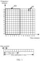
- a minimum resource granularity in time domain is one orthogonal frequency division multiplexing (orthogonal frequency division multiplexing, OFDM) symbol, and a minimum granularity in frequency domain is one subcarrier.
- OFDM symbol and one subcarrier form one time-frequency resource element, that is, a resource element/resource element (resource element, RE).
- RE resource element/resource element
- An RE is used as a basic unit for resource mapping at a physical layer.
- All OFDM symbols in one slot (slot) and 12 subcarriers in frequency domain may form a resource block (resource block, RB).
- An RB is used as a basic unit for LTE resource scheduling.
- One slot may include six or seven symbols.
- One frame is 10 ms and includes 10 subframes, and each subframe includes two slots. Different from that in LTE, a quantity of slots included in one subframe in NR varies based on a subcarrier spacing, and a quantity of symbols in each slot is also different from that in LTE and is fixed at 14.
- Table 1 compares signals used for network synchronization, cell coverage strength measurement, and channel estimation by using an LTE air interface technology and an NR air interface technology.
- Table 1 Function 4G LTE 5G NR Synchronization between a terminal device and a network PSS/SSS (cell level) SSB (cell level) Cell coverage strength measured by a terminal device CRS (cell level) SSB (cell level) Channel estimation for demodulating data received by a terminal device CRS (cell level) DMRS (user level)
- the terminal device may implement synchronization by using a primary synchronization signal (primary synchronization signal, PSS) and a secondary synchronization signal (secondary synchronization signal, SSS) that are broadcast by a base station.
- PSS primary synchronization signal
- SSS secondary synchronization signal
- a concept of SSB is introduced.
- the SSB is mainly used for downlink synchronization and includes a PSS, an SSS, and a physical broadcast channel (PBCH).
- PBCH physical broadcast channel
- the PSS, the SSS, and the PBCH form an SSB in four consecutive OFDM symbols.
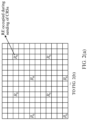
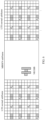
- FIG. 2(a) shows REs occupied when CRSs are sent on one antenna port of a base station in an LTE cell
- FIG. 2(b) shows REs occupied and REs that are muted to avoid transmission on other antennas in the LTE cell when CRSs are sent on two antenna ports of the base station
- FIG. 2(c)-1 and FIG. 2(c)-2 show REs occupied and REs that are muted to avoid transmission on other antennas in the LTE cell when CRSs are sent on four antenna ports of the base station.
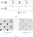
- time domain resources occupied by the SSB of the NR cell in a periodicity of 20 ms are sparser than time domain resources occupied by a PSS/an SSS of LTE in a subframe. This can reduce resource overheads and improve resource utilization.
- the NR cell needs to avoid a resource location at which the LTE cell sends a CRS, which decreases the resource utilization of the NR cell.
- a terminal device in the NR cell may support avoidance via puncturing.
- FIG. 4 shows resource occupation statuses of one RB of an NR cell and one RB of an LTE cell.
- FIG. 4 shows an example of a location of an RE used by the NR cell and a location of an RE that needs to be punctured by the NR cell to avoid the resources for the CRS of the LTE cell.
- (b) in FIG. 4 shows that RE locations of R0s are RE locations occupied by a CRS of the LTE cell in one RB, and a resource occupied by the CRS is at fixed RE locations in full bandwidth and the CRS is periodically sent.
- the LTE cell also needs to avoid resources for an SSB of the NR cell; otherwise, a terminal device in the NR cell cannot measure the NR cell.
- a terminal device in the LTE cell is usually a legacy terminal.
- FIG. 5 once RE locations occupied by some CRSs are punctured for sending an SSB by the NR cell, channel estimation performed by the terminal device in the LTE cell is distorted, affecting performance of the terminal device in the LTE cell.
- a CRS of the LTE cell is used for channel estimation, joint channel estimation and filtering in time domain and frequency domain are used. Therefore, in the LTE cell, distortion of channel estimation on a CRS of a subframe affects not only an RB of a current slot, but also spreads to other RBs, and even leads to distortion of channel estimation on subsequent consecutive subframes.
- physical downlink control channels (common physical downlink control channel, PDCCH) of both the LTE cell and the NR cell are defined to occupy the first three symbols of each subframe.
- PDCCH physical downlink control channel
- MBSFN multicast broadcast single frequency network
- the MB SFN subframe is a subframe format introduced in LTE to support a special broadcast service. If the MBSFN subframe is configured, an ordinary terminal device in the LTE cell does not perform CRS parsing for the MBSFN subframe. Therefore, deterioration of demodulation performance caused by distortion of channel estimation performed using the CRS can be avoided.
- the NR cell may continue to be normally used to send an SSB, a broadcast message, and the like, and does not avoid sending of CRSs of the LTE cell.
- the LTE cell cannot perform data transmission in the MBSFN subframe, in other words, one complete subframe is lost for the LTE cell.
- the NR cell sends an SSB every 20 ms, three MBSFN subframes may need to be configured for LTE considering that the NR cell also needs to send other system information (remaining minimum system information, RMSI) and paging (paging) messages.
- RMSI system information
- paging paging
- not all LTE terminal devices can identify the MBSFN subframe, and subframes before and after the MBSFN subframe are used by the terminal device to perform CRS measurement and channel estimation.
- the MBSFN subframe does not resolve the problem of an insufficient PDCCH capacity of the NR cell.
- an embodiment of this application provides a resource configuration method to solve a problem that demodulation performance of a conventional LTE terminal device deteriorates because a CRS of an LTE cell needs to avoid an SSB of an NR cell.
- the method may be applied to a base station to configure a resource for a signal in the LTE cell and configure a resource for a signal in the NR cell.
- asymmetric spectrum sharing is proposed.
- An NR bandwidth for spectrum sharing by an LTE cell and an NR cell of a base station is greater than an LTE bandwidth.
- a signal allocated in the dedicated bandwidth for the NR cell is not interfered with by a signal sent by the LTE cell, and correspondingly, a signal sent in the dedicated bandwidth for the NR cell does not interfere with sending of a signal of the LTE cell.
- an MBSFN subframe does not need to be configured for the LTE cell, thereby reducing a loss of the LTE cell, and further avoiding a compatibility problem that a low-end terminal device in LTE cannot identify the MB SFN subframe, thereby implementing smooth evolution from 4G to 5G.
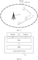
- a network architecture in this application may include an access network device 70 and a terminal device 71.
- the access network device 70 may include a base band unit (base band unit, BBU) and a remote radio unit (remote radio unit, RRU)/active antenna unit (active antenna unit, AAU). Because this application relates to spectrum sharing between 4G and 5G, the BBU and the RRU/AAU need to have a capability of processing both an LTE signal and an NR signal.
- the RRU in the access network device 70 is connected to an antenna feeder system (that is, an antenna) (where the RRU and the antenna may form an AAU), and the BBU and the RRU may be separated for use as required.
- the access network device 70 may also use another universal hardware architecture, and is not limited to the universal hardware architecture shown in FIG. 8 .
- the NR cell and the LTE cell share one BBU.
- a coverage range of the NR cell is the same as a coverage range of the LTE cell.
- the NR cell corresponds to one BBU
- the LTE cell corresponds to one BBU
- the BBU of the NR cell and the BBU of the LTE cell communicate in a wired/wireless mode.
- the terminal device may be implemented by using a structure shown in FIG. 9 .
- a terminal device 900 is a mobile phone
- FIG. 9 shows a universal hardware architecture of the mobile phone for description.
- the mobile phone shown in FIG. 9 may include components such as a radio frequency (radio frequency, RF) circuit 910, a memory 920, another input device 930, a display screen 940, a sensor 950, an audio circuit 960, an I/O subsystem 970, a processor 980, and a power supply 990.
- RF radio frequency
- the display screen 940 is a user interface (user interface, UI), and the display screen 940 may include a display panel 941 and a touch panel 942.
- the mobile phone may include more or fewer components than those shown in the figure.
- the mobile phone may further include functional modules or components such as a camera and a Bluetooth module. Details are not described herein again.
- the processor 980 is connected to the RF circuit 910, the memory 920, the audio circuit 960, the I/O subsystem 970, and the power supply 990 respectively.
- the I/O subsystem 970 is connected to the another input device 930, the display screen 940, and the sensor 950 respectively.
- the RF circuit 910 may be configured to receive and send a signal during an information receiving and sending process or during a call process. In particular, after receiving downlink information of a base station, the RF circuit sends the downlink information to the processor 980 for processing.
- the memory 920 may be configured to store a software program and a software module. By running the software program and module stored in the memory 920, the processor 980 performs various function applications and data processing of the mobile phone.
- the another input device 930 may be configured to receive inputted digital or character information, and generate a key signal input related to user settings and function control of the mobile phone.
- the display screen 940 may be configured to display information inputted by a user or information provided for a user and various menus of the mobile phone, and may further receive a user input.
- the sensor 950 may be an optical sensor, a motion sensor, or another sensor.
- the audio circuit 960 may provide an audio interface between a user and the mobile phone.
- the I/O subsystem 970 is configured to control an external input/output device, and the external device may include an input controller, a sensor controller, and a display controller of another device.
- the processor 980 is a control center of the mobile phone 900.
- the processor is connected to each part of the entire mobile phone through various interfaces and cables.
- the processor performs various functions of the mobile phone 900 and processes data by running or executing the software program and/or module that are/is stored in the memory 920 and invoking data stored in the memory 920, to perform overall monitoring on the mobile phone.
- the power supply 990 (such as a battery) is configured to supply power to the foregoing components.
- the power supply may be logically connected to the processor 980 by using a power management system, to implement functions such as charging, discharging, and power consumption management by using the power management system.
- An embodiment of this application provides a resource configuration method. As shown in FIG. 10 , the method includes the following steps.
- An access network device obtains first configuration information, where the first configuration information includes a bandwidth range of an NR cell, and the bandwidth range of the NR cell includes a dedicated frequency domain resource of the NR cell and a frequency domain resource shared by the NR cell and an LTE cell.
- the access network device may include a BBU, an RRU, and an antenna, or the access network device includes a BBU and an AAU.
- the obtaining first configuration information may be specifically performed by the BBU in the access network device.
- the first configuration information may be configured for the BBU manually or in another manner.
- the NR cell and the LTE cell share symmetric spectra, that is, the bandwidth range of the NR cell is the same as a bandwidth range of the LTE cell.
- the bandwidth range configured for the NR cell in this application includes the dedicated frequency domain resource of the NR cell and the frequency domain resource shared by the NR cell and the LTE cell.
- the access network device may configure, in the dedicated frequency domain resource of the NR cell, relatively important signals that are prone to interference in the NR cell.
- These signals may include a synchronization channel, a broadcast channel, a system message, a paging channel, a random access channel, and the like of the NR cell.
- the access network device sends the first configuration information to a terminal device in the NR cell.
- the BBU may send the obtained first configuration information to the terminal device by using the RRU/AAU.
- the terminal device may receive, based on the first configuration information, a signal sent by the access network device.
- the terminal device receives the foregoing relatively important signals that are prone to interference, because resources allocated to these signals are on the dedicated frequency domain resource of the NR cell, the terminal device in the NR cell does not need to avoid a signal of the LTE cell when receiving these signals, for example, does not need to avoid a CRS signal of the LTE cell.
- demodulation channel estimation distortion caused by the CRS of the LTE cell avoiding a signal of the NR cell can also be avoided.
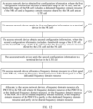
- An embodiment of this application provides a resource configuration method. As shown in FIG. 12 , the method includes the following steps: 121.
- An access network device obtains first configuration information, where the first configuration information includes a bandwidth range of an NR cell, and the bandwidth range of the NR cell includes a dedicated frequency domain resource of the NR cell and a frequency domain resource shared by the NR cell and an LTE cell.
- a bandwidth range configured by a BBU for the NR cell may include a bandwidth value and a frequency location.
- the bandwidth value may be 30 MHz, and the frequency location may indicate an FR1 frequency, an FR2 frequency, or the like.
- the bandwidth range may include a start frequency and an end frequency of a bandwidth.
- the start frequency is 2110 MHz
- the end frequency is 2140 MHz.
- the 30 MHz bandwidth includes the dedicated frequency domain resource of the NR cell, for example, 10 MHz. In other words, only the NR cell allocates a resource on the 10 MHz, and does not share the 10 MHz resource with the LTE cell.
- the 30 MHz bandwidth further includes the 20 MHz frequency domain resource shared by the NR cell and the LTE cell. In other words, both the NR cell and the LTE cell can allocate a resource on the 20 MHz.
- the bandwidth range of the NR cell is applicable to uplink and downlink time-frequency resource allocation in the NR cell.
- the access network device sends the first configuration information to a terminal device in the NR cell.
- the BBU may carry the first configuration information in a first system message, and periodically send the first system message in a broadcast manner to the terminal device in the NR cell, so that the terminal device that needs to access the NR cell learns, in a timely manner, the bandwidth range allocated to the NR cell.
- the terminal device in the NR cell may receive the first configuration information of the NR cell sent by the BBU.
- the access network device obtains second configuration information, where the second configuration information includes a bandwidth range of the LTE cell, and the bandwidth range of the LTE cell includes the frequency domain resource shared by the LTE cell and the NR cell.
- the BBU may further configure a bandwidth range for the LTE cell, where the bandwidth range includes the frequency domain resource shared by the LTE cell and the NR cell. Similar to the NR cell, the bandwidth range configured by the BBU for the LTE cell may also include a bandwidth value and a frequency location, or include a start frequency and an end frequency of a bandwidth. For example, when the bandwidth value is 20 MHz, it means that the 20 MHz is a frequency domain resource shared by the LTE cell and the NR cell.
- the bandwidth range of the LTE cell is applicable to uplink and downlink time-frequency resource allocation in the LTE cell.
- the bandwidth range of the NR cell configured by the BBU in this application is greater than the bandwidth range of the LTE cell.
- the bandwidth range of the NR cell is 30 MHz, and the bandwidth range of the LTE cell is 20 MHz, the bandwidth of the NR cell is 10 MHz greater than the bandwidth of the LTE cell.
- 20 MHz in the bandwidth of the NR cell is the frequency domain resource shared with the LTE cell, and 10 MHz in the bandwidth of the NR cell is the dedicated frequency domain resource of the NR cell.
- the access network device sends the second configuration information to a terminal device in the LTE cell.
- the terminal device in the LTE cell may receive the second configuration information of the LTE cell sent by the BBU.
- the BBU may carry the second configuration information in a second system message, and periodically send the second configuration information in a broadcast manner to the terminal device in the LTE cell, so that the terminal device that needs to access the LTE cell learns, in a timely manner, the bandwidth range allocated to the LTE cell.
- one access network device may cover both the NR cell and the LTE cell, and coverage ranges of the NR cell and the LTE cell are the same.
- both the first configuration information and the second configuration information may be sent to an RRU/AAU by using one BBU and then broadcast.
- information about the NR cell may be forwarded to the terminal device in the NR cell by using the LTE cell.
- the access network device includes a BBU1, a BBU2, an RRU, and an antenna
- the BBU1 corresponds to the NR cell
- the BBU2 corresponds to the LTE cell
- the BBU 1 may first send the first configuration information to the BBU2, the BBU2 sends the first configuration information to the RRU, and then the RRU broadcasts the first configuration information by using the antenna; and the BBU2 directly broadcasts the second configuration information by using the RRU and the antenna.
- the access network device may alternatively be that different BBUs correspond to different RRUs, that is, a BBU sends configuration information by using a corresponding RRU and an antenna.
- Step 124 is optional.
- the access network device may send the second configuration information to another access network device, and the another access network device sends the second configuration information.
- the access network device allocates a frequency domain resource to a first signal in the NR cell, where the frequency domain resource of the first signal is on the dedicated frequency domain resource.
- the BBU may allocate, on the dedicated frequency domain resource of the NR cell, frequency domain resources to some relatively important signals that are prone to interference and that affect access of the terminal device, where these signals are defined as the first signal.
- the BBU may allocate the resource on the dedicated frequency domain resource of the NR cell.
- the first signal may include at least one of the following signals: a signal used by the terminal device to synchronize with the access network device, a signal used by the terminal device to perform a timing function with the access network device, a signal used by the terminal device to obtain cell channel state information, a signal used by the terminal device to determine a cell to be camped on, and a signal used by the terminal device to access the access network device.
- the signal used by the terminal device to synchronize with the access network device may include an SSB;
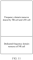
- FIG. 13 is a schematic diagram of uplink time-frequency resource allocation and downlink time-frequency resource allocation of an LTE cell and an NR cell, where a frequency domain resource shared by the NR cell and the LTE cell and a dedicated frequency domain resource of the NR cell are shown.
- the dedicated frequency domain resource shown in FIG. 13 includes a frequency domain resource of a PDCCH, a frequency domain resource of an SSB, and a frequency domain resource of a PRACH of the NR cell
- the dedicated frequency domain resource may further include frequency domain resources of the TRS, the CSI-RS, the DMRS, and the like.
- the BBU may allocate a time-frequency resource of the NR cell to the terminal device in the NR cell in a subsequent access procedure by applying the foregoing signal that can be used for allocating a resource on a dedicated time-frequency resource.
- the terminal device may learn a time-frequency resource of the SSB by searching for a synchronization channel on different frequencies.
- a frequency domain resource in the determined time-frequency resource of the SSB is on the dedicated frequency domain resource of the NR cell.
- the BBU may carry a time-frequency resource of the PRACH of the NR cell and a time-frequency resource of the common PDCCH in the broadcast SSB.
- the resource of the PRACH of the NR cell carried in the SSB is on the dedicated frequency domain resource of the NR cell.
- the terminal device may receive the SSB on the time-frequency resource of the SSB.
- the terminal device may obtain the time-frequency resource of the PRACH from the SSB, and the time-frequency resource of the PRACH determined by the terminal device is on the dedicated frequency domain resource of the NR cell. In this way, the terminal device may receive the PRACH on the determined frequency domain resource of the PRACH, and access the NR cell on the PRACH.
- the resource of the common PDCCH carried in the SSB is also on the dedicated frequency domain resource of the NR cell.
- the terminal device may obtain the time-frequency resource of the common PDCCH by parsing the SSB, and the time-frequency resource of the common PDCCH determined by the terminal device is on the dedicated frequency domain resource of the NR cell. In this way, the terminal device may receive the common PDCCH on the determined frequency domain resource of the common PDCCH.
- the BBU allocates the frequency domain resource of the SSB of the NR cell on the dedicated frequency domain resource of the NR cell
- the SSB can be prevented from being interfered with by a CRS sent by the LTE cell, and interference caused by the SSB sent by the NR cell to a legacy terminal device in the LTE cell can also be avoided.
- the access network device allocates a frequency domain resource of a PDCCH to the NR cell, where the frequency domain resource of the PDCCH is on the dedicated frequency domain resource, or the frequency domain resource of the PDCCH is on the shared frequency domain resource, orone part of the frequency domain resource of the PDCCH is on the dedicated frequency domain resource and the other part is on the shared frequency domain resource.
- the BBU may perform data communication with the terminal device.
- the BBU may first send DCI to the terminal device.
- the DCI carries a time-frequency resource of a PDCCH allocated by the BBU to the NR cell.
- the allocated frequency domain resource may be on the dedicated frequency domain resource of the NR cell, or may be on the shared frequency domain resource, or one part may be on the dedicated frequency domain resource and the other part may be on the shared frequency domain resource, so that the BBU may send the PDCCH to the terminal device on the time-frequency resource of the PDCCH.
- the terminal device when receiving the DCI, may obtain the time-frequency resource of the PDCCH by demodulating the DCI.
- a frequency domain resource in the time-frequency resource of the PDCCH may be on the dedicated frequency domain resource of the NR cell, or may be on the shared frequency domain resource, or one part may be on the dedicated frequency domain resource and the other part may be on the shared frequency domain resource. In this way, the terminal device may receive the PDCCH on the determined time-frequency resource of the PDCCH.
- the BBU when allocating the frequency domain resource of the PDCCH to the terminal device, may determine a location of the frequency domain resource based on a user level, a service type, and the like of the terminal device. For example, a frequency domain resource of a PDCCH allocated to a terminal device with a relatively high user level may be on the dedicated frequency domain resource of the NR cell, and a frequency domain resource of a PDCCH allocated to a terminal device with a relatively low user level may be on the shared frequency domain resource, or one part of allocated frequency domain signal is on the dedicated frequency domain resource and the other part is on the shared frequency domain resource.
- a frequency domain resource of a PDCCH allocated to a terminal device with a relatively high service type priority may be on the dedicated frequency domain resource of the NR cell
- a frequency domain resource of a PDCCH allocated to a terminal device with a relatively low service type priority may be on the shared frequency domain resource, or one part of allocated frequency domain signal is on the dedicated frequency domain resource and the other part is on the shared frequency domain resource.
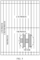
- an RB that is in the dedicated frequency domain resource of the NR cell and that is allocated by the BBU may be comprehensively scheduled and allocated with an RB that is in the shared frequency domain resource and that is dynamically allocated to the NR cell, so that available resources of the NR cell can be maximized. For example, referring to FIG.
- a frequency domain resource of a PUCCH of the NR cell may be partly in the dedicated frequency domain resource and partly in the shared frequency domain resource of the NR cell.
- Resource allocation manners of a physical uplink shared channel (physical uplink shared channel, PUSCH), a PDCCH, a physical downlink shared channel (physical downlink shared channel, PDSCH), and a physical uplink control channel (physical uplink control channel, PUCCH) of an NR cell are similar, and in all these resource allocation manners, an RB in the dedicated frequency domain resource of the NR cell may be comprehensively scheduled and allocated with an RB that is in the shared frequency domain resource and that is dynamically allocated to the NR cell.
- the access network device when the access network device allocates a frequency domain resource to a second signal in the NR cell, the access network device may preferentially allocate the dedicated frequency domain resource to the second signal.
- the second signal includes any one of the following signals: a PDCCH, a PDSCH, a PUCCH, and a PUSCH.
- frequency domain resources of these second signals may be allocated on the dedicated frequency domain resource or the shared frequency domain resource of the NR cell.
- the BBU preferentially allocates the dedicated frequency domain resource to the second signal. In this way, when the second signal is sent on the dedicated frequency domain resource, interference from a signal sent by the LTE cell can be avoided, and interference to the signal sent by the LTE cell can also be avoided.
- a time domain resource is generally allocated as the first three symbols in each slot.
- the BBU may allocate the first three symbols to the PDCCH of the NR cell on the dedicated frequency domain resource of the NR cell.
- the PDCCH of the NR cell may occupy the zeroth symbol, the first symbol, and the second symbol in a 10 M frequency domain resource that is dedicated to the NR cell and that is configured by the BBU.
- a PDCCH resource capacity of the NR cell can be increased, the performance deterioration of the NR cell caused by insufficient control channels can be avoided, and the quantity of UEs that can be admitted by the NR cell can be increased.
- the LTE air interface technology determines that resources for a CRS need to be densely distributed in entire time-frequency resource space, the resources for a CRS are densely distributed in the shared frequency domain resource. If frequency domain resources of some downlink time-frequency resources allocated by the BBU to the NR cell are on the shared frequency domain resource, the BBU needs to puncture some time-frequency resources of the NR cell and deliver a rate matching template to avoid a resource conflict with a CRS of the LTE cell. Correspondingly, the terminal device needs to identify and avoid locations of the punctured resources based on the rate matching template, to demodulate and restore data. In other words, based on the rate matching template, the terminal device may determine that some REs are punctured, that is, no data is received on the REs, and therefore may not demodulate signals of these REs.
- the BBU may send the rate matching template to the terminal device in the NR cell.
- the rate matching template indicates the terminal device not to receive, when receiving the PDCCH or the PDSCH, data on a resource indicated by the rate matching template.
- the BBU needs to puncture some time-frequency resources of the PDCCH or the PDSCH and deliver the rate matching template.
- the terminal device may identify punctured REs based on the rate matching template, to skip receiving data on these punctured REs.
- resource allocation of the LTE cell may comply with an LTE protocol constraint. For example, it is constrained in a protocol that a frequency domain resource of a PUCCH of an LTE cell is at two ends of an LTE bandwidth range. In this case, in this application, the frequency domain resource of the PUCCH of the LTE cell may also be distributed at two ends of the shared frequency domain resource.
- the BBU needs to send a signal to the terminal device by using the RRU/AAU
- the first configuration information, the second configuration information, the frequency domain resource of the first signal, the frequency domain resource of the second signal, and the like obtained by the BBU in this application all need to be sent to the terminal device by using the RRU/AAU. Therefore, the RRU/AAU side also needs to support a resource configuration of the BBU in this application.
- the BBU may send the first configuration information and the second configuration information to the RRU/AAU, to notify the RRU/AAU to learn the bandwidth range of the NR cell and the bandwidth range of the LTE cell that are configured by the BBU.
- the BBU may further send third configuration information to the RRU/AAU, where the third configuration information includes first indication information and second indication information, the first indication information indicates a frequency domain resource location of the NR cell, and the second indication information indicates a frequency domain resource location of the LTE cell.
- the RRU/AAU may receive the third configuration information sent by the BBU.
- the frequency domain resource location of the NR cell includes a dedicated frequency domain resource location, and the dedicated frequency domain resource location includes a frequency domain resource location of an SSB of the NR cell, a frequency domain resource location of a PRACH of the NR cell, a partial resource location of a frequency domain resource of a PDCCH of the NR cell, and the like.
- the RRU/AAU when sending a signal to the terminal device, the RRU/AAU can support the principle of resource allocation by the BBU.
- the resource configuration method provided in this application may be a more robust spectrum sharing method.
- user perception of a low-end LTE terminal device in an LTE cell is not affected. That is, a user of a conventional LTE terminal device does not perceive existence of an NR cell. Therefore, the terminal device in the LTE cell may continue to access the LTE cell and perform uplink and downlink data transmission based on a resource allocated by the BBU.
- some common channels (for example, SSBs) of the NR cell that need to be avoided are allocated on the dedicated frequency domain resource. Therefore, no common channel of the NR cell that needs to be avoided exists within the bandwidth range of the LTE cell.
- the frequency domain resource division method shown in FIG. 13 is used as an example.
- the terminal device in the LTE cell may determine that an available bandwidth range is 20 MHz. In this way, when there is no NR user in the NR cell, an actual available bandwidth range of the terminal device in the LTE cell is 20 MHz, and the terminal in the LTE cell does not need to support carrier aggregation or an MBSFN subframe.
- the 30 MHz bandwidth is divided into two carriers: 20 MHz and 10 MHz, each carrier needs to support spectrum sharing between an LTE cell and an NR cell, and a single terminal device combines resources of the two carriers in a carrier aggregation manner.
- Afinal effect may be as follows:
- the MBSFN mechanism does not need to be used, to resolve the problem that demodulation performance of a terminal device in an LTE cell deteriorates because a CRS in LTE avoids an SSB in NR, that is, a compatibility problem of a legacy terminal device during use of the MBSFN mechanism can be avoided.
- a compatibility problem of a legacy terminal device during use of the MBSFN mechanism can be avoided.
- no performance loss of the legacy LTE terminal device can be achieved.
- the terminal device in the NR cell and the terminal device in the NR cell can obtain relatively high available bandwidth resources, thereby maximizing utilization of frequency domain resources.
- the communication apparatus includes corresponding hardware and/or software modules for performing the functions.
- the communication apparatus may be the foregoing access network device or BBU.
- Algorithm steps in the examples described with reference to the embodiments disclosed in this specification can be implemented by hardware or a combination of hardware and computer software in this application. Whether a function is performed by hardware or hardware driven by computer software depends on a particular application and a design constraint of the technical solutions. A person skilled in the art may use different methods to implement the described functions for each particular application with reference to the embodiments, but it should not be considered that the implementation goes beyond the scope of this application.
- module division may be performed on the communication apparatus based on the foregoing method examples.
- various functional modules may be divided corresponding to various functions, or two or more functions may be integrated into one processing module.
- the integrated module may be implemented by hardware. It should be noted that, module division in the embodiments is an example and is merely logical function division. During actual implementation, there may be another division manner.
- FIG. 14 is a schematic diagram of possible compositions of an access network device 140 involved in the foregoing embodiments.
- the access network device 140 may include a processing unit 1401 and a transceiver unit 1402.
- the processing unit 1401 may include the foregoing BBU
- the transceiver unit 1402 may include the foregoing RRU and antenna, or include the AAU.
- the processing unit 1401 may be configured to support the access network device 140 in performing step 101, step 121, step 123, step 125, step 126, and the like, and/or another process of the technology described in this specification.
- the transceiver unit 1402 may be configured to support the access network device 140 in performing step 102, step 122, step 124, and the like, and/or another process of the technology described in this specification.
- the access network device 140 provided in this embodiment is configured to perform the foregoing resource allocation method, and therefore can achieve a same effect as the foregoing implementation method.
- the access network device 140 may include a processing module and a communication module.
- the processing module may be configured to control and manage an action of the access network device 140, for example, may be configured to support the access network device 140 in performing the steps performed by the processing unit 1401.
- the communication module may be configured to support the access network device 140 in communicating with another device, for example, communicating with a terminal device.
- the processing module may be a processor or a controller.
- the processing module may implement or execute logical blocks, modules, and circuits in various examples described with reference to content disclosed in this application.
- the processor may alternatively be a combination for implementing a computing function, for example, a combination of one or more microprocessors or a combination of a digital signal processor (digital signal processor, DSP) and a microprocessor.
- the access network device may further include a memory, configured to store a program and/or an instruction of the access network device.
- the memory may further store data.
- the communication module may be specifically a transceiver, for example, a device that interacts with another electronic device, such as a radio frequency circuit, a Bluetooth chip, or a Wi-Fi chip.
- the access network device 140 involved in this embodiment may be an access network device 15 having a structure shown in FIG. 15 , including a processor 150, a transceiver 151, and a memory 152.
- the access network device 15 may include one or more processors 150.
- the processor 150 may be a general-purpose processor or a dedicated processor.
- the processor may be a baseband processor or a central processing unit.
- the baseband processor may be configured to process a communication protocol and communication data.
- the central processing unit may be configured to: control a base station or a chip, execute a software program, and process data of the software program.
- the processor 150 may also store instructions and/or data.
- An embodiment of this application further provides a communication system.
- the communication system includes the foregoing access network device and the foregoing terminal device.
- An embodiment of this application further provides a computer-readable medium, configured to store computer program code.
- the computer program includes an instruction used for performing the method performed by the access network device in the foregoing communication methods.
- the readable medium may be a read-only memory (read-only memory, ROM) or a random access memory (random access memory, RAM). This is not limited in the embodiments of this application.
- the computer program product includes an instruction.
- an access network device is enabled to perform an operation corresponding to the access network device in the foregoing method.
- An embodiment of this application further provides a system chip.
- the system chip includes a processing unit and a communication unit.
- the processing unit may be, for example, a processor, and the communication unit may be, for example, an input/output interface, a pin, a circuit, or the like.
- the processing unit may execute a computer instruction, so that a communication apparatus to which the chip is applied performs an operation of the access network device in the foregoing method provided in the embodiments of this application.
- the disclosed apparatuses and methods may be implemented in other manners.
- the described apparatus embodiments are merely examples.
- the module or unit division is merely logical function division, and may be other division during actual implementation.
- a plurality of units or components may be combined or may be integrated into another apparatus, or some features may be ignored or not performed.
- the displayed or discussed mutual couplings or direct couplings or communication connections may be implemented through some interfaces.
- the indirect couplings or communication connections between the apparatuses or units may be implemented in electrical, mechanical, or another form.
- the units described as separate parts may or may not be physically separate, and parts displayed as units may be one or more physical units, that is, may be located in one place, or may be distributed on a plurality of different places. Some or all of the units may be selected based on actual requirements to achieve the objectives of the solutions of the embodiments.
- functional units in the embodiments of this application may be integrated into one processing unit, or each of the units may exist alone physically, or two or more units may be integrated into one unit.
- the integrated unit may be implemented in a form of hardware, or may be implemented in a form of a software functional unit.
- the integrated unit When the integrated unit is implemented in a form of a software functional unit and sold or used as an independent product, the integrated unit may be stored in a readable storage medium.
- the software product is stored in a storage medium and includes several instructions for instructing a device (which may be a single-chip microcomputer, a chip, or the like) or a processor (processor) to perform all or some of the steps of the methods in the embodiments of this application.
- the foregoing storage medium includes any medium that can store program code, such as a USB flash drive, a removable hard disk, a ROM, a RAM, a magnetic disk, or an optical disc.
Landscapes
- Engineering & Computer Science (AREA)
- Signal Processing (AREA)
- Computer Networks & Wireless Communication (AREA)
- Quality & Reliability (AREA)
- Mobile Radio Communication Systems (AREA)
Applications Claiming Priority (2)
| Application Number | Priority Date | Filing Date | Title |
|---|---|---|---|
| CN202010622058.5A CN113891332A (zh) | 2020-07-01 | 2020-07-01 | 一种资源配置方法和装置 |
| PCT/CN2021/102558 WO2022001903A1 (zh) | 2020-07-01 | 2021-06-25 | 一种资源配置方法和装置 |
Publications (2)
| Publication Number | Publication Date |
|---|---|
| EP4171093A1 true EP4171093A1 (de) | 2023-04-26 |
| EP4171093A4 EP4171093A4 (de) | 2023-12-06 |
Family
ID=79012661
Family Applications (1)
| Application Number | Title | Priority Date | Filing Date |
|---|---|---|---|
| EP21831881.4A Pending EP4171093A4 (de) | 2020-07-01 | 2021-06-25 | Ressourcenkonfigurationsverfahren und -vorrichtung |
Country Status (5)
| Country | Link |
|---|---|
| US (1) | US12543159B2 (de) |
| EP (1) | EP4171093A4 (de) |
| JP (1) | JP7600490B2 (de) |
| CN (1) | CN113891332A (de) |
| WO (1) | WO2022001903A1 (de) |
Families Citing this family (8)
| Publication number | Priority date | Publication date | Assignee | Title |
|---|---|---|---|---|
| KR20230046001A (ko) * | 2021-09-29 | 2023-04-05 | 삼성전자주식회사 | 대역폭에 기반한 무선 통신 시스템의 운용 방법 및 장치 |
| US20240357430A1 (en) * | 2021-10-29 | 2024-10-24 | Qualcomm Incorporated | Coordinated long-term evolution (lte) and new radio (nr) coexistence in vehicle-to-everything (v2x) network |
| CN118786695A (zh) * | 2022-04-15 | 2024-10-15 | Oppo广东移动通信有限公司 | Pdcch的接收方法、发送方法、装置、设备及介质 |
| CN117042105A (zh) * | 2022-04-29 | 2023-11-10 | 维沃移动通信有限公司 | 同步信号确定方法、资源选择和预留方法、装置、终端及存储介质 |
| US20230388985A1 (en) * | 2022-05-24 | 2023-11-30 | Dell Products, L.P. | Multi-band spectrum allocation for cellular networks |
| CN115515242B (zh) * | 2022-09-21 | 2024-05-14 | 中国电信股份有限公司 | 搜索空间配置方法、物理下行控制信道搜索方法及装置 |
| CN116761219A (zh) * | 2023-07-07 | 2023-09-15 | 中国电信股份有限公司技术创新中心 | 资源配置方法、装置、电子设备及存储介质 |
| WO2026027040A1 (en) * | 2024-07-31 | 2026-02-05 | Nokia Technologies Oy | Multi-rat resource sharing profiles for wireless communications |
Family Cites Families (24)
| Publication number | Priority date | Publication date | Assignee | Title |
|---|---|---|---|---|
| WO2015123870A1 (zh) * | 2014-02-21 | 2015-08-27 | 华为技术有限公司 | 使用无线资源的控制方法、装置、网元及终端 |
| CN104618914B (zh) | 2015-01-04 | 2018-03-27 | 湖北工业大学 | 一种基于频谱合约的多用户协作频谱共享方法 |
| EP3764581A1 (de) * | 2016-03-30 | 2021-01-13 | IDAC Holdings, Inc. | Durch long-term-evolution unterstützter nr-flexibler funkzugriff |
| US10405332B2 (en) * | 2016-09-06 | 2019-09-03 | Samsung Electronics Co., Ltd. | Coexistence of different radio access technologies or services on a same carrier |
| EP3549302B1 (de) | 2017-01-04 | 2024-10-30 | LG Electronics Inc. | Verfahren und vorrichtung zur gemeinsamen nutzung eines spektrums zwischen 3gpp-lte und nr in drahtloskommunikationssystem |
| US10925046B2 (en) * | 2017-01-05 | 2021-02-16 | Huawei Technologies Co., Ltd. | Signaling indication for flexible new radio (NR) long term evolution (LTE) coexistence |
| CN110169002B (zh) * | 2017-01-09 | 2021-11-30 | Lg 电子株式会社 | 无线通信系统中发送参考信号的方法及其装置 |
| CN108366375B (zh) | 2017-01-26 | 2021-09-14 | 华为技术有限公司 | 一种共享下行频谱的方法和装置 |
| CN109041067B (zh) * | 2017-06-12 | 2021-03-23 | 维沃移动通信有限公司 | 一种通信方法、移动终端、基站及计算机可读存储介质 |
| CN107509205B (zh) | 2017-08-17 | 2020-11-06 | 湖北工业大学 | 一种基于契约理论的协作频谱共享动态激励机制设计方法 |
| CN109757132B (zh) * | 2017-09-08 | 2023-06-13 | 瑞典爱立信有限公司 | 用于多载波配置的随机接入 |
| KR102695314B1 (ko) * | 2018-03-30 | 2024-08-13 | 광동 오포 모바일 텔레커뮤니케이션즈 코포레이션 리미티드 | 업링크 제어 정보 전송 방법 및 장치 |
| CN110839248B (zh) * | 2018-08-17 | 2021-06-08 | 华为技术有限公司 | 一种配置方法及设备 |
| JP2020053849A (ja) * | 2018-09-27 | 2020-04-02 | シャープ株式会社 | 基地局装置、端末装置、通信方法、および、集積回路 |
| KR102660113B1 (ko) * | 2018-10-11 | 2024-04-23 | 삼성전자주식회사 | 이동통신 시스템에서 단말, 기지국 및 그 동작 방법 |
| CN115499929B (zh) * | 2018-11-02 | 2026-02-24 | 展讯通信(上海)有限公司 | 唤醒信号的资源确定、配置方法及装置、终端、基站 |
| CN111356161B (zh) * | 2018-12-20 | 2022-05-13 | 华为技术有限公司 | 无线网络通信方法、基站、终端及通信装置 |
| CN109982328B (zh) | 2019-01-31 | 2022-09-13 | 湖北工业大学 | 一种基于深度神经网络的协作频谱共享智能契约设计方法 |
| CN109818693B (zh) | 2019-02-03 | 2021-10-22 | 湖北工业大学 | 一种动态非对称信息条件下多阶段协作频谱共享契约方法 |
| EP3939196A4 (de) * | 2019-03-15 | 2023-01-04 | Telefonaktiebolaget Lm Ericsson (Publ) | Netzwerkknoten und verfahren zur dynamischen gemeinsamen spektrumsnutzung zwischen funkzugangstechnologien |
| US20200366440A1 (en) * | 2019-05-17 | 2020-11-19 | Qualcomm Incorporated | Long term evolution common reference signal-assisted new radio tracking |
| CN110278563B (zh) | 2019-05-23 | 2022-07-22 | 华为技术有限公司 | 确定频谱资源的方法及装置 |
| CN110300155B (zh) | 2019-05-31 | 2022-01-04 | 中国人民解放军国防科技大学 | 一种基于区块链的认知物联网频谱数据共享方法 |
| WO2021022391A1 (en) * | 2019-08-02 | 2021-02-11 | Qualcomm Incorporated | Inter-numerologies interference avoidance for long term evolution (lte) and 5g new radio (nr) spectrum sharing |
-
2020
- 2020-07-01 CN CN202010622058.5A patent/CN113891332A/zh active Pending
-
2021
- 2021-06-25 EP EP21831881.4A patent/EP4171093A4/de active Pending
- 2021-06-25 WO PCT/CN2021/102558 patent/WO2022001903A1/zh not_active Ceased
- 2021-06-25 JP JP2022580892A patent/JP7600490B2/ja active Active
-
2022
- 2022-12-28 US US18/147,127 patent/US12543159B2/en active Active
Also Published As
| Publication number | Publication date |
|---|---|
| JP2023531546A (ja) | 2023-07-24 |
| JP7600490B2 (ja) | 2024-12-17 |
| US20230139778A1 (en) | 2023-05-04 |
| WO2022001903A1 (zh) | 2022-01-06 |
| US12543159B2 (en) | 2026-02-03 |
| CN113891332A (zh) | 2022-01-04 |
| EP4171093A4 (de) | 2023-12-06 |
Similar Documents
| Publication | Publication Date | Title |
|---|---|---|
| US12543159B2 (en) | Resource configuration method and apparatus | |
| EP3843439B1 (de) | Verfahren und vorrichtung zur konfiguration von sidelink-ressourcen | |
| US11019499B2 (en) | Signal transmission apparatus and method, and wireless access node | |
| US11924141B2 (en) | Communication method, network device, and terminal device | |
| EP3817480A1 (de) | Signalübertragungsverfahren und -vorrichtung | |
| WO2021146998A1 (zh) | 一种确定初始带宽部分bwp的方法、装置及存储介质 | |
| EP3777284A1 (de) | Breitbandiger pdcch für unlizenziertes band für new radio | |
| EP3896885A1 (de) | Drahtlosnetzwerkkommunikationsverfahren und endgerätevorrichtung | |
| GB2498932A (en) | Distributed carrier aggregation on unlicensed bands | |
| EP3562229A1 (de) | Uplink-übertragungssteuerungsverfahren und -vorrichtung sowie kommunikationssystem | |
| EP3902323A1 (de) | Kommunikationsverfahren und -vorrichtung | |
| CN114731635A (zh) | 用于无线通信的方法及设备 | |
| US20250055663A1 (en) | Frame structure configuration method and device for full duplex communication | |
| WO2022021241A1 (zh) | 同步信号块的传输方法、装置、设备及存储介质 | |
| US20240064860A1 (en) | Procedure and signaling for sidelink drx alignment | |
| CN115119183A (zh) | 一种通信方法及通信装置 | |
| US20250184105A1 (en) | Method and apparatus of configuring subband for full duplex in wireless communication system | |
| US12075435B2 (en) | Communication method and apparatus | |
| CN114651496B (zh) | 一种通信方法及装置 | |
| CN118511613B (zh) | 寻呼早期指示位置确定 | |
| US20230224856A1 (en) | Paging early indication location determination | |
| US20260012961A1 (en) | Method for sidelink transmission and terminal device | |
| US20260040222A1 (en) | Method and apparatus for beam management for low-power signal transmission and reception | |
| WO2019237347A1 (zh) | 资源分配和接收方法、装置及通信系统 | |
| KR20260017955A (ko) | 저전력 신호 송수신을 위한 빔 관리 방법 및 장치 |
Legal Events
| Date | Code | Title | Description |
|---|---|---|---|
| STAA | Information on the status of an ep patent application or granted ep patent |
Free format text: STATUS: THE INTERNATIONAL PUBLICATION HAS BEEN MADE |
|
| PUAI | Public reference made under article 153(3) epc to a published international application that has entered the european phase |
Free format text: ORIGINAL CODE: 0009012 |
|
| STAA | Information on the status of an ep patent application or granted ep patent |
Free format text: STATUS: REQUEST FOR EXAMINATION WAS MADE |
|
| 17P | Request for examination filed |
Effective date: 20230118 |
|
| AK | Designated contracting states |
Kind code of ref document: A1 Designated state(s): AL AT BE BG CH CY CZ DE DK EE ES FI FR GB GR HR HU IE IS IT LI LT LU LV MC MK MT NL NO PL PT RO RS SE SI SK SM TR |
|
| DAV | Request for validation of the european patent (deleted) | ||
| DAX | Request for extension of the european patent (deleted) | ||
| A4 | Supplementary search report drawn up and despatched |
Effective date: 20231107 |
|
| RIC1 | Information provided on ipc code assigned before grant |
Ipc: H04W 72/23 20230101ALN20231031BHEP Ipc: H04W 56/00 20090101ALN20231031BHEP Ipc: H04W 72/0453 20230101ALI20231031BHEP Ipc: H04L 5/00 20060101ALI20231031BHEP Ipc: H04W 16/14 20090101AFI20231031BHEP |