EP4171341B1 - Reinigungssystem und verfahren zum betreiben eines reinigungssystems - Google Patents
Reinigungssystem und verfahren zum betreiben eines reinigungssystems Download PDFInfo
- Publication number
- EP4171341B1 EP4171341B1 EP21729431.3A EP21729431A EP4171341B1 EP 4171341 B1 EP4171341 B1 EP 4171341B1 EP 21729431 A EP21729431 A EP 21729431A EP 4171341 B1 EP4171341 B1 EP 4171341B1
- Authority
- EP
- European Patent Office
- Prior art keywords
- cleaning
- user
- interaction
- cart
- cleaning system
- Prior art date
- Legal status (The legal status is an assumption and is not a legal conclusion. Google has not performed a legal analysis and makes no representation as to the accuracy of the status listed.)
- Active
Links
Images


Classifications
-
- A—HUMAN NECESSITIES
- A47—FURNITURE; DOMESTIC ARTICLES OR APPLIANCES; COFFEE MILLS; SPICE MILLS; SUCTION CLEANERS IN GENERAL
- A47L—DOMESTIC WASHING OR CLEANING; SUCTION CLEANERS IN GENERAL
- A47L13/00—Implements for cleaning floors, carpets, furniture, walls, or wall coverings
- A47L13/10—Scrubbing; Scouring; Cleaning; Polishing
- A47L13/50—Auxiliary implements
- A47L13/51—Storing of cleaning tools, e.g. containers therefor
-
- A—HUMAN NECESSITIES
- A47—FURNITURE; DOMESTIC ARTICLES OR APPLIANCES; COFFEE MILLS; SPICE MILLS; SUCTION CLEANERS IN GENERAL
- A47L—DOMESTIC WASHING OR CLEANING; SUCTION CLEANERS IN GENERAL
- A47L11/00—Machines for cleaning floors, carpets, furniture, walls, or wall coverings
- A47L11/40—Parts or details of machines not provided for in groups A47L11/02 - A47L11/38, or not restricted to one of these groups, e.g. handles, arrangements of switches, skirts, buffers, levers
- A47L11/4002—Installations of electric equipment
-
- A—HUMAN NECESSITIES
- A47—FURNITURE; DOMESTIC ARTICLES OR APPLIANCES; COFFEE MILLS; SPICE MILLS; SUCTION CLEANERS IN GENERAL
- A47L—DOMESTIC WASHING OR CLEANING; SUCTION CLEANERS IN GENERAL
- A47L11/00—Machines for cleaning floors, carpets, furniture, walls, or wall coverings
- A47L11/40—Parts or details of machines not provided for in groups A47L11/02 - A47L11/38, or not restricted to one of these groups, e.g. handles, arrangements of switches, skirts, buffers, levers
- A47L11/4002—Installations of electric equipment
- A47L11/4005—Arrangements of batteries or cells; Electric power supply arrangements
-
- A—HUMAN NECESSITIES
- A47—FURNITURE; DOMESTIC ARTICLES OR APPLIANCES; COFFEE MILLS; SPICE MILLS; SUCTION CLEANERS IN GENERAL
- A47L—DOMESTIC WASHING OR CLEANING; SUCTION CLEANERS IN GENERAL
- A47L11/00—Machines for cleaning floors, carpets, furniture, walls, or wall coverings
- A47L11/40—Parts or details of machines not provided for in groups A47L11/02 - A47L11/38, or not restricted to one of these groups, e.g. handles, arrangements of switches, skirts, buffers, levers
- A47L11/4002—Installations of electric equipment
- A47L11/4008—Arrangements of switches, indicators or the like
-
- A—HUMAN NECESSITIES
- A47—FURNITURE; DOMESTIC ARTICLES OR APPLIANCES; COFFEE MILLS; SPICE MILLS; SUCTION CLEANERS IN GENERAL
- A47L—DOMESTIC WASHING OR CLEANING; SUCTION CLEANERS IN GENERAL
- A47L11/00—Machines for cleaning floors, carpets, furniture, walls, or wall coverings
- A47L11/40—Parts or details of machines not provided for in groups A47L11/02 - A47L11/38, or not restricted to one of these groups, e.g. handles, arrangements of switches, skirts, buffers, levers
- A47L11/4011—Regulation of the cleaning machine by electric means; Control systems and remote control systems therefor
-
- A—HUMAN NECESSITIES
- A47—FURNITURE; DOMESTIC ARTICLES OR APPLIANCES; COFFEE MILLS; SPICE MILLS; SUCTION CLEANERS IN GENERAL
- A47L—DOMESTIC WASHING OR CLEANING; SUCTION CLEANERS IN GENERAL
- A47L11/00—Machines for cleaning floors, carpets, furniture, walls, or wall coverings
- A47L11/40—Parts or details of machines not provided for in groups A47L11/02 - A47L11/38, or not restricted to one of these groups, e.g. handles, arrangements of switches, skirts, buffers, levers
- A47L11/4072—Arrangement of castors or wheels
-
- A—HUMAN NECESSITIES
- A47—FURNITURE; DOMESTIC ARTICLES OR APPLIANCES; COFFEE MILLS; SPICE MILLS; SUCTION CLEANERS IN GENERAL
- A47L—DOMESTIC WASHING OR CLEANING; SUCTION CLEANERS IN GENERAL
- A47L11/00—Machines for cleaning floors, carpets, furniture, walls, or wall coverings
- A47L11/40—Parts or details of machines not provided for in groups A47L11/02 - A47L11/38, or not restricted to one of these groups, e.g. handles, arrangements of switches, skirts, buffers, levers
- A47L11/4075—Handles; levers
Definitions
- the present invention relates to a cleaning system comprising a cleaning cart and a method for operating a cleaning system with a cleaning cart.
- cleaning trolleys are of great importance in the area of daily cleaning. Particularly noteworthy are cleaning tasks that have to be carried out manually in larger buildings, for example office buildings, hotels, care facilities, hospitals, airports, event buildings or the like.
- the cleaning trolleys are used to carry cleaning utensils. Examples of this are in particular manually operated cleaning tools, containers for storing cleaning accessories, cleaning liquids or cleaning chemicals, containers for collecting dirty liquids or waste, cleaning cloths or other objects for surface cleaning.
- the cleaning trolleys are usually provided with holders for picking up and/or carrying such cleaning utensils.
- the cleaning trolleys include rollers so that they can be moved by a user, usually by hand, over a floor surface.
- a handle for the user is provided, for example.
- the rollers of the cleaning trolleys can be fixed, ie unguided.
- the rollers can be swivel rollers.
- a mixture of unguided rollers and swivel rollers can also be provided.
- the cleaning trolleys usually comprise a frame on which the rollers are arranged.
- an open frame can be considered as the frame, for example for arranging containers.
- a closed frame in the sense of a body can also be considered as the frame, which comprises, for example, side walls and/or doors for closing off a storage space for cleaning utensils.
- cleaning tasks When cleaning tasks are carried out using cleaning trolleys, it is desirable to carry out cleaning tasks efficiently and in line with requirements, for example when there are a number of rooms to be cleaned. It may be necessary to clean the rooms in a predetermined order. It may be necessary to carry out different cleaning tasks in different rooms, and different cleaning utensils may be used. For this reason, for example, it is necessary to equip the cleaning trolley as required when work begins, with all the necessary cleaning utensils preferably being available and superfluous cleaning utensils not being carried along.
- a "room” can be considered to be any area to be cleaned.
- the room can have physical boundaries such as walls. Alternatively or additionally, virtual boundaries can be provided in the sense of a predeterminable definition of where the room ends without the presence of physical boundaries.
- the room can be located indoors or outdoors. Accordingly, a room can be, for example, a room, a corridor, a hall, a foyer, a path, a square or another type of open space.
- the EN 10 2018 111 423 B4 describes a cleaning system with a cleaning trolley and a data processing device.
- the cleaning trolley comprises a frame which is provided with a unique machine-readable identifier
- the cleaning trolley can therefore be identified in the data processing device.
- Sets of cleaning utensils tailored to cleaning tasks are stored in the data processing device.
- the status of the cleaning trolley is stored in the data processing device.
- WO 2019/092062 A1 describes a cleaning cart which has a support body and a communication device holder for receiving a mobile communication device, wherein the communication device holder is fixed to the support body.
- the EN 10 2018 117 670 A1 describes a cleaning device in the form of a scrubber-drier.
- the cleaning device comprises at least one cleaning tool for cleaning an object to be cleaned, an operating unit for a user, which comprises at least one operating element for operating the cleaning device, a control unit for processing operating instructions and a holder arranged on the operating unit for an external additional device that can be assigned to the cleaning device.
- the additional device has a display device with an image display and can be removably positioned in a defined position in the holder. Display information can be transferred from the cleaning device to the additional device positioned in the holder for display on the image display.
- the object of the present invention is to provide a cleaning system and a method for operating a cleaning system which enables cleaning tasks to be carried out in a user-friendly and reliable manner.
- a cleaning system comprising a cleaning trolley and an external additional device
- the cleaning trolley comprises a frame with rollers for moving on a floor surface, at least one holder for receiving and/or carrying of cleaning utensils and an interaction device with a manually operable interaction element
- the additional device is designed to be portable and a user application program for processing cleaning-related information is stored on the additional device in an executable manner and/or can be operated via the additional device, wherein the interaction device and the additional device can be coupled to one another via a communication connection, and wherein input information for operating the user application program can be transmitted from the interaction device to the additional device and processed by the latter depending on an actuation of the interaction element by the user.
- an external additional device is used in addition to the cleaning trolley.
- the cleaning system comprises more than one cleaning trolley and/or more than one external additional device.
- the cleaning trolleys and/or the additional devices can be designed identically or differently. It can be provided that a respective additional device can be used optionally with one of the cleaning trolleys or vice versa.
- the additional device can be used to operate a user application program that can, for example, be stored on the additional device itself - in particular as a so-called “app" - and/or can be stored remotely from the additional device and executed there - for example on a server or in a "cloud".
- the user application program allows the processing of cleaning-related information, for example for the execution of a cleaning plan within the framework of which cleaning tasks are carried out using the cleaning cart.
- the cleaning cart includes an interaction device that can be coupled to the additional device via at least a unidirectional communication connection.
- the interaction device includes the interaction element.
- the interaction element can be operated manually, and it can preferably also be operated by the user wearing gloves, which, for example, make it difficult or even impossible to use a touch-sensitive display unit of the additional device.
- User inputs via the interaction element can be transmitted to the additional device and processed by it to operate the user application program.
- the user's inputs can be used as cleaning-related information when processing a cleaning plan. It is conceivable, for example, that the user acknowledges instructions from the user application program or confirms the planned or completed cleaning of rooms. Possible inputs are discussed below.
- the interaction device with the interaction element forms a user-friendly interface for interaction with the user application program via the additional device.
- Operating the additional device itself i.e. physically on the additional device, can preferably be dispensed with as a result. More hygienic operation of the additional device is made possible by the fact that the user can use the interaction element. Nevertheless, it is preferably provided that the user can operate the additional device physically as an alternative or in addition.
- the interaction element preferably allows for increasing the acceptance of the use of additional devices in connection with cleaning carts and a user application program for carrying out cleaning tasks. For example, if the additional device is used without an interaction element, cleaning service providers, customers and third parties could get the impression that the user is not working but is wasting time operating the additional device. This impression can be prevented by using the interaction element on the cleaning cart.
- the communication connection between the interaction device and the additional device can be wireless and/or wired.
- the communication connection is a radio connection.
- a Bluetooth connection or a WiFi connection can be provided.
- an NFC connection between the interaction device and the additional device is conceivable, which requires spatial proximity of these two components.
- This proximity can be advantageous and/or desirable, for example to ensure a secure communication connection and/or to ensure that a display unit of the additional device can be used and is in the user's field of vision.
- the interaction device and the interaction element are advantageously designed in such a way that they are system-independent and can function with additional devices of different designs and the software stored thereon (platform-independent and/or software-independent).
- the interaction device can, for example, comprise a microprocessor for processing the user's inputs on the interaction element. It is conceivable that a computer program can run on the microprocessor, in particular via embedded software.
- the software can be updateable. Updates for the software can, for example, be transferred from the additional device to the interaction device.
- the at least one holder for cleaning utensils can be designed in different ways.
- at least one container, at least one holding part for hanging and/or for clamping and/or locking the cleaning utensil, a support part on which cleaning utensils can be placed, etc. are provided.
- the additional device comprises an output unit.
- cleaning-related information from the user application program can be output to the user via the output unit.
- an optical output unit in the form of a display unit can be provided as the output unit, in particular with a controllable image display.
- an acoustic and/or a haptic output unit can be provided as an output unit.
- the additional device can be, for example, a smartphone or a tablet computer.
- conventional operation of the additional device can preferably be be possible.
- physical interaction is particularly conceivable, for example via a touch-sensitive display unit (touchscreen).
- voice control and/or gesture control using a camera on the additional device is provided.
- output information from the user application program can be transmitted from the additional device to the interaction device and if the interaction device includes a notification unit for issuing notifications to the user depending on the output information.
- a bidirectional communication connection can exist between the additional device and the interaction device.
- the user can be provided with notifications on the notification unit, for example for processing a cleaning plan.
- the information unit can be, for example, an optical information unit.
- the optical information unit can be designed in different ways. For example, a controllable image display is provided.
- the information unit can be or include a lighting device that provides information, for example by illuminating it using different colors. Lighting elements, for example LED diodes, can be provided.
- an optical information unit may have a single-segment display or a multi-segment display.
- the information unit can be designed to be acoustic and/or haptic. This allows information to be provided acoustically via a loudspeaker and/or haptically, for example through vibration.
- the brightness of the optical indicator unit, the volume of the acoustic indicator unit and/or the intensity of the haptic indicator unit can be adjustable.
- the interaction element includes or forms the information unit.
- a separate information unit can be saved in this way. This enables a structurally simple and compact design of the interaction device.
- Information that is issued on the interaction element can preferably be easily perceived by the user. If the interaction element is in the user's field of vision when it is operated, the user can immediately perceive any information. Therefore, arranging the information unit on the interaction element increases the likelihood that information will be perceived by the user.
- the interaction element is a rotary knob or includes a rotary knob.
- the interaction element can be operated particularly easily.
- a diameter of approximately 5 cm to 10 cm can be advantageous, for example, to make the rotary knob easier to handle.
- an axis around which the rotary knob can be rotated can, for example, have an angle of 45° or less relative to a vertical.
- a "vertical" is considered to be an axis perpendicular to a contact plane defined by the rollers with the floor surface, the contact plane being considered to be horizontally aligned and assuming that the cleaning cart is used as intended on the floor surface.
- the angle may preferably be less than 30° with respect to the vertical.
- the rotary knob may preferably have a knurling with strips and/or knobs on an outer circumference to facilitate handling by the user, for example when wearing gloves.
- the interaction device can, for example, evaluate a position of the rotary knob and/or a rotation speed of the rotary knob to determine the input information.
- the interaction element is a push button or toggle switch or includes one.
- the interaction device can, for example, input information
- a reset element can be provided, through which the interaction element returns to an initial position in the sense of a basic position after pressure or tilting.
- Haptic feedback from the interaction element when the user enters inputs can be advantageous.
- the interaction element is a combined turn-tilt button and/or turn-push button or includes one of these.
- the interaction device and in particular the interaction element is preferably waterproof, but at least splash-proof and/or dust-proof. This prevents a possible malfunction of the interaction device due to unwanted ingress of water and/or dust.
- at least one standard of the IP protection class standard is met.
- the interaction device is at least IP54-compliant, preferably at least IP65-compliant.
- the cleaning trolley advantageously comprises a handle device with at least one handle element for guiding the cleaning trolley by a user.
- the cleaning trolley can be moved over the floor surface in a user-friendly manner using the handle device.
- the handle device comprises, for example, two handle elements arranged at a distance from one another. It can be provided that the handle elements are aligned essentially horizontally and can be gripped vertically by the user with the fingers. For example, a handle device with two handle elements that are aligned essentially vertically and can be gripped horizontally by the user with the fingers can prove to be ergonomic.
- the at least one handle element can be height-adjustable and thus preferably adapted to the body size of the user.
- the interaction element is arranged on the handle device or is enclosed by it. This allows the user to easily access the interaction element. This increases user-friendliness.
- the interaction element is positioned between two handle elements of the handle device that are arranged at a distance from one another, in particular essentially in the middle of the handle device.
- the interaction device is arranged entirely on the handle device or is enclosed by it.
- the handle device can be detachably attached to the frame of the cleaning trolley. This advantageously offers the possibility of attaching the handle device to the cleaning trolley in a different position, depending on the user's wishes.
- the handle device can be attached to a different type of cleaning trolley, for example.
- the interaction element is arranged on the handle device as explained above.
- the advantages of the invention can be achieved with several cleaning trolleys to which the handle device can be optionally attached without several interaction devices having to be provided for this purpose.
- the handle device and the frame comprise, for example, corresponding connecting elements.
- the connecting elements can, for example, enable a clamping and/or locking connection.
- a blocking device can be provided to prevent the handle device from becoming detached from the cleaning trolley.
- Connecting and/or disconnecting the handle device can preferably be carried out manually and/or without tools.
- the additional device is located at a distance from the cleaning trolley, even if there is an existing communication connection with the interaction device.
- a wireless communication connection is particularly advantageous.
- the user carries the additional device on their body, for example in a bag.
- the cleaning cart includes a receiving unit with a holder for receiving the additional device.
- the additional device can be positioned on or in the holder. It preferably occupies a defined position on the cleaning cart. This can be particularly advantageous for the reliability of the communication connection.
- a display unit of the additional device is in the user's field of vision. For example, instructions from the user application program are shown on the display unit and can therefore be more easily recognized by the user when the additional device is positioned in the holder.
- a surface normal of the display unit has an angle to the horizontal of approximately 20° to 70°, wherein the horizontal in this case is considered to be aligned parallel to the contact plane of the rollers.
- the holder is arranged on the handle device or is enclosed by it. This advantageously makes it possible for the additional device with display unit to be particularly easy for the user to see and/or operate.
- the handle device is detachable, the holder can be attached together with the additional device to another cleaning trolley and/or to a different position on the cleaning trolley.
- the advantages that can be achieved by providing the holder can therefore preferably be achieved on more than just one cleaning trolley.
- the receptacle is preferably positioned between two handle elements arranged at a distance from one another, in particular substantially in the middle of the handle device. If the interaction element is arranged on the handle device, the receptacle is preferably arranged behind the interaction element in the access direction, so that the interaction element can be accessed and is not covered by the additional device.
- the receiving unit is arranged entirely on the handle device.
- the holder is advantageously variable in size. Accordingly, the holder unit can comprise or form an adapter unit that can be adapted to additional devices of different sizes and allows the inclusion of different additional devices.
- the receptacle is arranged between two holding elements that are movable relative to one another and that the respective additional device can be held in a form-fitting manner between the holding elements.
- a holding element is arranged, for example, on a support part that is designed to be movable in order to change the size of the receptacle.
- the support part is, for example, movable on the handle device. The position of the support part relative to the handle device can, for example, be fixable so that the size of the holder is maintained and the additional device is therefore held particularly reliably.
- the receiving unit can comprise a support part to which the additional device can be placed.
- the additional device can be leaned flat against the support part with a rear side facing away from a display unit.
- the support part is in particular the support part mentioned above that can be moved relative to the handle device.
- the receiving unit preferably comprises a blocking element for securing the additional device against removal from the holder. This ensures that the additional device cannot be inadvertently removed from the holder. In particular, improper removal can be prevented, for example, by securing the blocking element with a locking cylinder or a similar security device and the holder can only be released when the correct key is used to remove the additional device.
- the additional device can be secured directly or indirectly via the blocking element.
- the holder is blocked against expansion by the blocking element, for example, so that the additional device cannot be removed.
- a blocking element can be provided which engages with a support part of the receiving unit and thereby prevents displacement of the support part, in particular relative to the handle device.
- a charging unit for charging the additional device is arranged on the receiving unit or if the receiving unit includes a charging unit. This allows an energy storage device of the additional device to be charged while it is being positioned in the receiving unit. This extends the service life of the additional device, particularly with regard to carrying out cleaning tasks according to a cleaning plan.
- the additional device can be charged contactlessly by induction.
- an inductive charging unit is provided on the support part mentioned above, against which the additional device is leaning.
- the additional device can be charged via cable.
- an electrical connection element is provided for connecting a charging cable for the additional device.
- the connection element is, for example, a USB socket.
- the cleaning cart preferably comprises an electrical energy storage device for providing electrical energy for the interaction device and/or for the additional device.
- the energy storage device is, for example, a rechargeable battery, which is preferably removable.
- a receptacle is preferably provided for the energy storage device, which is conveniently arranged on the handle device.
- the energy storage device preferably acts on the charging unit, via which the additional device can be charged.
- the user application program can, for example, be stored in an executable form on the additional device and is installed there, for example, as an "app”.
- the cleaning system comprises a data processing device which is arranged spatially remote from the cleaning trolley and the additional device and which is or can be connected to the additional device in communication, and that cleaning-related information of the user application program from the additional device to the data processing device and/or vice versa.
- the data processing device can be designed as a server and/or as a plurality of interconnected computers, for example as a "cloud”.
- the user application program can be executed on the data processing device, for example.
- Cleaning-related information can be exchanged between the additional device and the data processing device. In this sense, for example, input information can be processed by the additional device and transmitted to the data processing device for processing by the user application program. Conversely, information from the user application program can be transmitted from the data processing to the additional device.
- Outputs can be provided, for example, via an indication unit of the additional device and/or an indication unit on the cleaning cart.
- a cleaning plan is provided via the data processing device and transmitted to the user application program on the additional device. This makes it possible, for example, to centrally create and manage cleaning plans for a number of cleaning carts and users, with the cleaning tasks being processed in a decentralized manner.
- a report on the processing of the cleaning plan can be transferred from the user application program on the additional device to the data processing device and evaluated or collected there.
- a cleaning plan can advantageously be stored in the user application program.
- the cleaning plan can include cleaning-related information.
- the cleaning plan serves in particular to inform the user about cleaning tasks, preferably with a view to thorough, systematic and time-saving cleaning. It is desirable to carry out cleaning tasks flexibly, depending, for example, on the occupancy or accessibility of a room and/or depending on of cleaning tasks that have to be carried out at short notice, the order of cleaning tasks can be changed, added to, deleted or the cleaning plan can be influenced in some other way.
- the cleaning plan includes, for example, information about rooms to be cleaned.
- the cleaning plan includes, for example, room-related information about objects to be cleaned in at least one room. It may be intended that information is available about objects in at least one room that should not be cleaned.
- the cleaning plan includes, for example, room-related information about the type of cleaning of at least one object to be cleaned in a room.
- the cleaning plan includes, for example, information regarding the equipment of the cleaning cart for processing the cleaning plan.
- the cleaning cart can be equipped with the necessary cleaning utensils when it starts operations.
- the cleaning plan can in particular store which cleaning utensils are intended for which cleaning task or in general, in particular for which room and/or for which object within a room.
- the cleaning plan is preferably linked to a clearly identifiable cleaning cart.
- user inputs can advantageously be processed via the interaction element for implementing the cleaning plan.
- the cleaning plan can be changed, especially after processing has begun. This enables, for example, versatile, demand-based cleaning processes in the sense of "demand-based cleaning".
- the user can be informed of a change in the upcoming cleaning tasks, for example depending on the occupancy or accessibility of a room. Inaccessible rooms and the cleaning tasks associated with them can be skipped. Cleaning tasks can be added for accessible rooms. Required, inserted cleaning tasks can thus be integrated into the cleaning plan. The user can be informed of this, for example, by means of a message (e.g. a push message).
- the cleaning system in particular the cleaning cart, can comprise at least one sensor device.
- Information and/or states can advantageously be recorded via the at least one sensor device with a view to reliably carrying out cleaning, for example with a view to processing the cleaning plan.
- the cleaning system in particular the cleaning cart, comprises a sensor device with which a room in which the cleaning cart is positioned can be identified. Determining the room enables, for example, the user application program to inform the user about a cleaning task to be carried out in this room. Information in this regard can be issued, for example, via the additional device and/or an information unit on the cleaning cart. Entry into the room can be logged as an alternative or in addition to monitoring the processing of cleaning tasks.
- the position of the cleaning cart can be determined instead of the position of the additional device, for example by identifying the room.
- the room can be identified, for example, using landmarks ("beacons") arranged on or in the room, which can be detected via Bluetooth, for example. Alternatively or additionally, identification can be carried out using RFID elements that are assigned to the room and arranged on or in the room.
- the at least one sensor device of the cleaning cart can advantageously comprise or form an RFID reader for detecting RFID elements.
- instructions for cleaning the room can advantageously be provided, depending on a cleaning plan stored in the user application program.
- a map of the rooms to be cleaned with the cleaning trolley is stored in the user application program, in particular linked to a cleaning plan. When the room is identified, it is therefore possible to determine the position of the cleaning trolley within the map.
- Cleaning tasks that are assigned to the rooms are advantageously stored in the cleaning plan in such a way that the number and/or distance of empty trips during which no cleaning is carried out is kept as low as possible.
- By identifying rooms it is advantageously possible to record the sequence in which the rooms are cleaned.
- the efficiency of the processing of the cleaning plan can be determined and, in particular, it can be determined whether the rooms have been visited with the smallest possible number and/or distance of empty trips during which no cleaning is carried out.
- the user can be instructed on how to carry out cleaning tasks in order to ensure the best possible cleaning result, to avoid incorrect cleaning and/or to enable the resource-saving use of cleaning utensils.
- the user is instructed on which cleaning utensil to use. This can be done, for example, via the additional device or an information unit on the cleaning trolley. In a preferred embodiment, the information elements mentioned below are provided.
- information elements are arranged on the cleaning trolley's containers and/or on the cleaning utensil holders, which can be activated depending on the identified room.
- the activation can preferably take place depending on a cleaning plan for the room stored in the user application program.
- the information elements can be designed optically or acoustically, for example.
- Light elements for example, can be used as optical information elements. The light elements can be activated for the cleaning utensil to be used. In this way, the user can be guided to take the correct cleaning utensils using a so-called "pick by light" system.
- confirmation that a specified cleaning utensil has been removed can be made via the interaction element.
- the cleaning system in particular the cleaning cart, can preferably comprise a sensor device with which the user's additional device and/or an authorization carrier of the user can be detected. For example, this has the purpose of verifying that the user is authorized in order to prevent misuse and/or theft. It can be provided that the user must be authorized to drive the cleaning cart. If the identification is positive, i.e. the user is authorized to drive the cleaning cart, a brake on the cleaning cart can be unlocked, for example. If the detection is negative, if the user is not authorized, the brake remains blocked and the cleaning cart cannot be moved.
- the identification of the additional device can advantageously be carried out via the communication connection between the identification device and the additional device.
- the identification of the authorization carrier can be carried out, for example, by an RFID reader on the cleaning cart, whereby the authorization carrier is an RFID element.
- the cleaning system in particular the cleaning trolley, preferably comprises a sensor device with which cleaning utensils can be detected, which are carried on the cleaning trolley.
- cleaning utensils can be detected individually or collectively by the sensor device and marked as cleaning utensils that must be carried or not carried by issuing a positive or negative acknowledgement. This makes equipping the cleaning trolley easier.
- the cleaning utensil can be checked for correctness by means of the sensor device and the user can be given feedback in this regard.
- the recognition of the cleaning utensils can, for example, be RFID-based, whereby an RFID reader is arranged on the cleaning trolley and the cleaning utensils contain RFID elements.
- the cleaning system in particular the cleaning cart, preferably comprises a sensor device with which the stock of consumables that are carried with the cleaning cart can be detected. For example, fill levels of containers and/or the number of cleaning cloths present or used are recorded. Depending on the stock, the user can be informed that consumables need to be replenished. In the event of excessive consumption, the user can be prompted to use cleaning utensils more sparingly. Monitoring the consumption of cleaning utensils can be used alternatively or in addition for documentation purposes, for example when cleaning cloths need to be changed after certain area performance, times or in certain rooms.
- the present invention also relates to a method.
- the present disclosure further relates to a cleaning cart according to the invention.
- the cleaning cart according to the invention according to the present disclosure can represent an independent invention independent of the presence of the interaction device.
- the interaction device can optionally be provided.
- the cleaning trolley comprises a frame with rollers for moving on a floor surface, at least one receptacle for receiving and/or carrying cleaning utensils and a handle device with at least one handle element for guiding the cleaning trolley by a user, wherein the handle device can be detachably secured to the frame of the cleaning trolley, and wherein the cleaning trolley comprises a receiving unit with a receptacle arranged on the handle unit for receiving a portable additional device.
- the additional device can in particular be a smartphone or a tablet computer.
- a user application program for processing cleaning-related information can be executable on the additional device.
- the user application program can be operated via the additional device.
- the user can interact with the user application program in particular via the additional device, especially for processing a cleaning plan with at least one cleaning job.
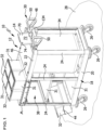
- FIG. 1 shows a perspective view of a partial view of a cleaning system according to the invention, designated overall by the reference number 10.
- the cleaning system 10 comprises in particular a cleaning cart 12 and a portable electronic additional device 14.
- the cleaning system 10 may include more than one cleaning cart and more than one additional device 14.
- the Figures 14 and 15 show further cleaning trolleys 100 and 200, and the Figures 3 and 8th show another additional device 300 instead of the additional device 14.
- the cleaning system 10 can comprise several cleaning carts and several additional devices, with at least one cleaning cart and one additional device being provided.
- the invention is explained below using the example of the cleaning cart 12 and the additional devices 14, 300.
- a component of the cleaning system 10 is a data processing device 16 arranged spatially away from the cleaning cart 12 and the additional device 14.
- this is only an optional component of the cleaning system 10 according to the invention.
- the cleaning trolley 12 comprises a frame 18 with a lower frame part 20 and an upper frame part 22 spaced apart from the latter in a vertical direction.
- the lower frame part 20 and the upper frame part 22 are connected to one another via support elements 24 in the form of profiles.
- Rollers 26 for moving the cleaning trolley 12 on a floor surface 28 are held on the frame base 20.
- the rollers 26 are swivel rollers.
- unguided rollers can be provided.
- the rollers 26 define a contact plane which, when the cleaning trolley 12 is used as intended, coincides with a plane defined by the floor surface 28. It is assumed, without limitation, that the floor surface 28 is aligned horizontally.
- Position and orientation information are to be understood in this case as referring to the intended use of the cleaning trolley 12 on the horizontally oriented floor surface 28.
- a handle device 30 is provided for gripping by the user (not shown in the drawing).
- the cleaning trolley 12 serves to carry cleaning utensils, in particular for manual cleaning.
- the cleaning trolley 12 comprises holders 31 for cleaning utensils.
- the receptacles 31 comprise, for example, containers 32 which are held on the frame 18 and are designed, for example, in the shape of a bucket.
- the containers 32 serve, for example, to hold cleaning fluids or cleaning cloths as well as manual cleaning tools (these are not shown) and can themselves be regarded as cleaning utensils.
- a container 34 for holding waste is held on the frame 18.
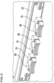
- receptacles 31 in the form of holding parts 36 can be fixed to the frame 18, which in Figure 1 hidden and in Figure 2 Manual cleaning tools such as mops, flat wipers or brooms can be held in place by force on the holding parts 36 and can be removed when required.
- the frame 18 is designed to be open and has no doors or side walls in order to close the receiving space 38 formed between the lower frame part 20 and the upper frame part 22.
- the cleaning trolleys 100 comprise doors 40 and side walls 42, so that the receiving space 38 is at least partially closed. It is understood that behind the doors 40 and the side walls 42, receptacles 31 for cleaning utensils can be provided.
- a ceiling wall 46 can be provided on the top of the frame 18.
- the handle device 30 comprises a base element 48 and two handle elements 50.
- the handle elements 50 are fixed to the base element 48 and spaced apart from one another.
- the handle elements 50 are held on the base element 48 in a height-adjustable manner.
- the handle elements 50 can be pivoted, for example, about a horizontally aligned axis 52 relative to the base element 48.
- a securing device 54 can be provided to secure the handle elements 50 in a respective position.
- the handle device 30 is ergonomically designed via the handle elements 50 and allows the cleaning trolley 12 to be guided for longer periods without fatigue.
- the handle elements 50 are aligned vertically in sections so that the user can grip them horizontally with his fingers. This hand position reduces the strain on the wrists and/or forearms.
- the handle device 30 can in particular be detachably attached to the cleaning trolley 12.
- the handle device 30 and the cleaning trolley 12 comprise corresponding connecting elements 56, 58.
- the connecting elements 56 are arranged on the side of the base element 48 facing the cleaning trolley 12 ( Figure 4 ).
- the connecting elements 56 comprise clamping elements 60 and locking elements 62.
- the connecting elements 58 are arranged on the upper frame part 22 ( Figure 7 ) and designed to correspond to the connecting elements 56.
- the connecting elements 58 comprise clamping receptacles 64 for the clamping elements 60 and locking receptacles 66 for the locking elements 62.
- the connecting elements 56, 58 can be brought into engagement with one another and the handle device 30 can thereby be releasably secured to the cleaning trolley 12.
- the handle device 30 comprises blocking elements 68 which are designed to secure the locking elements 62 from being released from the locking receptacles 66.
- the blocking elements 68 can, however, be transferred to a release position in order to enable the unlocking and thus the release of the handle device 30 from the cleaning trolley 12.
- the handle device 30 can be optionally fixed at a plurality of positions on the cleaning trolley 12.
- the cleaning trolley 12 can have connecting elements 58 at a plurality of positions, in particular on the upper frame part 22.
- the handle device 30 can preferably be detachably attached to other cleaning trolleys of the cleaning system 10.
- the Figures 14 and 15 show this by way of example for the cleaning trolleys 100 and 200.
- several connecting elements 58 can also be arranged on the other cleaning trolleys 100, 200 in such a way that the handle device 30 can be fixed in a plurality of positions on the cleaning trolleys 100, 200.
- the cleaning trolley 12 together with the handle device 30 can represent an independent invention within the scope of the present disclosure. The same applies to the cleaning trolleys 100 and 200.
- the additional device 14 is designed as a tablet computer 70.
- the tablet computer 70 comprises output units for outputting instructions to the user, specifically instructions from a user application program for cleaning tasks.
- an optical output unit is provided, designed as a display unit 72 with a controllable image display.
- acoustic and haptic output units are provided.
- the tablet computer 70 also includes a communication device 74, via which communication connections can be established and used.
- a communication device 74 via which communication connections can be established and used.
- the additional device 300 is designed as a smartphone 76.
- the smartphone 76 has dimensions that differ from the tablet computer 70, but it is also equipped with the corresponding output units, in particular the display unit 72, and the communication device 74.
- the cleaning cart 12 comprises a receiving unit 78 with a receptacle 80.
- the handle device 30 comprises the receiving unit 78. This proves to be advantageous because when the handle device 30 is repositioned, an additional device arranged in the receptacle 80 is also repositioned, for example on one of the other cleaning carts 100 or 200. Separate receiving units are not required.
- the arrangement of the holder 80 on the handle device 30 is advantageous so that the display unit 72 can be seen by the user and the content of the image display can be perceived in a simple manner.
- the physical interaction with the additional device 14 or 300 is made easier for the user by arranging the holder 80 on the handle device 30.
- the display unit 72 is designed in particular as a touch-sensitive touchscreen.
- voice control and/or gesture control of the additional device 14 or 300 there is the option of voice control and/or gesture control of the additional device 14 or 300.
- the receiving unit 78 is arranged on the base element 48.
- the base element 48 forms a holding element 82 on the top, on which the additional device 14 can be placed, in particular with a side surface (the following explanations apply accordingly to the additional device 300, which is Figure 3 shown as an example).
- the holding element 82 is, for example, groove-shaped in order to ensure a defined position of the additional device 14.
- the receiving unit 78 has a further holding element 84, which is positioned at a distance from the holding element 82 and is arranged above the latter.
- the holding element 84 is fixed to a support part 86 of the receiving unit 78 and is arranged on the end thereof, for example.
- the support part 86 is in engagement with the base element 48.
- the additional device 14 can be leaned against the support part 86 with the rear side facing away from the display unit 72. In particular, the additional device 14 can lie flat against the support part 86.
- the receptacle 80 is formed between the holding elements 82, 84 and the support part 86, in which the additional device 14 is preferably positioned in a form-fitting manner.
- the holding element 84 can also be designed in a groove shape for the positive reception of a side surface of the additional device 14.
- a surface normal of the display unit 72 is inclined upwards relative to the horizontal.
- the angle of inclination is preferably more than approximately 20°. This causes the display unit 72 to face the user and be easier to recognize.
- the support part 86 is designed to be movable and in particular displaceable relative to the base element 48. In particular, it is possible to displace the support part 86 relative to the base element 48 in a height direction, indicated by a double arrow 88, relative to the base element 48. This makes it possible to change the distance between the holding element 84 and the holding element 82.
- the receptacle 80 can be changed in size in this way.
- the ability to change the size of the holder 80 increases the versatility of the holder unit 78.
- the support element 86 passes through openings in an upper wall 90 and in a lower wall 92 of the base element 48 ( Figures 4 and 6 ). This includes in particular a guide for the support part 86, which makes it easier for the user to handle the receiving unit 78.
- the support part 86 can be fixed in a respective relative position to the base element 48.
- a blocking element 94 is provided.
- the support part 86 and the blocking element 94 can be brought into engagement in a plurality of positions of the support part 86.
- a toothing 96 is preferably provided on the support part 86, which can be brought into engagement with a corresponding toothing 98 of the blocking element 94 ( Figure 6 ).
- the blocking element 94 is designed as a slider 102, which is preferably displaceable in a corresponding guide 104 on the base element 48.
- a double arrow 106 in Figure 6 indicates the direction of movement.
- the teeth 96, 98 are disengaged so that the support part 86 can be moved.
- This offers in particular the possibility of expanding the holder 80 in order to remove the additional device 14.
- the holder 80 can be made smaller in order to fix the additional device 14.
- the slide 102 can assume an advanced engagement position in which the teeth 96, 98 are in engagement with each other. This ensures the Support part 86 against displacement so that the holder 80 is fixed in its size.
- the additional device 14 can be secured in the receptacle 80 via the blocking element 94 in the engagement position with the support part 86 when it is received in a form-fitting manner between the holding elements 82, 84.
- a securing device 108 is provided for fixing the blocking element 94 at least in the engaged position.
- the securing device 108 comprises, for example, a locking cylinder 110 with an eccentric arranged thereon, which engages in an opening of the blocking element 94 ( Figure 6 ).
- the locking cylinder 110 can only be turned with the mechanical key provided for this purpose.
- an additional device 14 accommodated in the holder 80 is protected against theft in this way.
- the additional device 14 can be released by means of the mechanical key used to open the locking cylinder 110.
- a charging unit 112 is provided on the receiving unit 78, via which the additional device 14 can be charged.
- the charging unit 112 comprises, for example, an inductive charging element 114, which is preferably integrated into the support part 86.
- electrical energy can be transferred from the charging element 114 to the energy storage device of the additional device 14.
- the charging unit 112 further comprises an electrical connection element 116, in this case designed as a USB socket.
- a charging cable that is connected to the additional device 14 can be connected to the connection element 116.
- the cleaning cart 12 comprises an energy storage device 118.
- the energy storage device 118 is arranged on the handle device 30.
- the energy storage device 118 is in this case a rechargeable battery 120, for example in the form of a Li-ion battery.
- the battery 120 can be detachably connected to a receptacle 122 on the handle device 30, which is arranged in this case on the lower wall 92. This makes it possible to charge the battery 120 externally to the cleaning cart 12. For example, the battery 120 is placed on the receptacle 122 when the cleaning cart 12 is put into operation.
- the charging unit 112 can be supplied with electrical energy via the energy storage device 118 in order to supply and in particular to charge the additional device 14.
- the energy storage device 118 also serves to supply electrical energy to other electrical components of the cleaning cart 12. These other components include in particular an interaction device 124, sensor devices 126, 128 and 158 and a control device 130.
- the devices 124, 126, 128, 158 and 130 can be fully or partially integrated into a common device. This device can, for example, be arranged on the handle device 30 or be included by it.
- the cleaning cart 12 comprises the interaction device 124, which will be discussed below.
- the interaction device comprises an interaction element 134 that can be manually operated by a user.
- the interaction element 134 serves to input of the user.
- Input information is transmitted from the interaction device 124 to the additional device 14 and can be processed by it.
- the interaction device 124 is arranged here on the handle device 30. As with the receiving unit 78, this offers the advantage that the interaction device 124 is also repositioned when the handle device 30 is attached to a different position on the cleaning cart 12 or on one of the other cleaning carts 100, 200. An additional interaction device 124 is not required.
- the handle device 30 advantageously comprises the interaction device 124.
- the interaction device 124 comprises a housing 136 which is inserted into an opening of the base element 48, in particular in the upper wall 90. To rest against an edge of the opening, the housing 136 comprises a flange-like contact area 138. The housing 136 engages in a gap between the upper wall 90 and the lower wall 92.
- the interaction element 134 is arranged above the base element 48.
- the interaction element 134 comprises a rotary knob, which simultaneously forms a push button and a toggle switch and accordingly forms a rotary-push-toggle switch.
- the interaction element 134 is referred to below for simplicity as button 140.
- the button 140 is mounted on the housing 136 so that it can rotate about a rotation axis 142. In addition, the button 140 can be tilted relative to the rotation axis 142 and pressed in the axial direction. The position of the button 140 relative to the housing 136 during rotation, the rotation speed, any tilt position and pressure on the button 140 can be evaluated by an electrical device 144 of the interaction device 124. Depending on this, input information can be provided by the interaction device 124.
- the button 140 is arranged on the handle device 30 such that it is arranged in front of the receptacle 80 with respect to an access direction.
- the receptacle 80, and thus the additional device 14, is arranged behind the button 140 with respect to the access direction. In this way, the button 140 is not covered by the additional device 14 and the user can easily access the button 140.
- the button 140 is arranged between the handle elements 50 and positioned substantially centrally on the handle device 30.
- the additional device 14 is arranged essentially centrally on the handle device 30.
- the button 140 is arranged on the handle device 30 such that the rotation axis 142 is inclined relative to the vertical.
- the angle of inclination is, for example, less than 45°, preferably less than 30°.
- the rotation axis 142 is inclined in the direction of the user positioned behind the handle device 30.
- the button 140 is dimensioned such that it can be easily grasped and operated by the user, especially when the user is wearing gloves.
- the button has a diameter of approximately 5 cm to 10 cm.
- a ribbing 146 is preferably provided on an outer circumference of the button 140.
- the ribbing 146 is formed, for example, by strips and/or by knobs.
- the button 140 is used to operate the additional device 14. In particular, it is possible to transmit input information to the additional device 14 via an input on the button 140.
- the interaction device 124 and the additional device 14 can be coupled to one another via a communication connection.
- the communication connection is preferably wireless.
- the communication connection is preferably bidirectional.
- a Bluetooth-based communication connection can be established between the additional device 14 and the interaction device 124.
- the previously mentioned input information which is triggered by the user via the button 140, can be transmitted from the interaction device 124 to the additional device 14.
- output information can be transmitted from the additional device 14 to the interaction device 124.
- interaction device 124 and the additional device 14 comprise cooperating communication devices 74, 141 for establishing the communication connection.
- an NFC connection or a WiFi connection can be used, for example.
- the interaction device 124 can comprise a notification unit in order to be able to issue notifications to the user depending on the output information transmitted to it. It is advantageous if the button 140 comprises or forms the notification unit.
- an optical display unit 148 with an image display is provided as the indication unit.
- an acoustic and/or a haptic indication unit can be provided, for example.
- the display unit 148 can display, for example, images, texts or videos to support cleaning tasks as explained below.
- the indication unit can be designed optically, but without an image display.
- a lighting device with one or more lighting elements is arranged on the button 140 in order to be able to display different colors.
- corona lighting One possibility is so-called corona lighting.
- a user application program is stored in an executable manner on the additional device 14, which assists the user in carrying out cleaning.
- a cleaning plan with cleaning tasks to be carried out by the user can be stored in the user application program.
- the interaction device 124 allows the user to communicate with the additional device 14 and in particular to operate it. By pressing the button 140, input information can be triggered, transmitted to the additional device 14 and processed by the additional device 14 as cleaning-related information for operating the user application program.
- output information of the user application program can be transmitted to the interaction device 124 and related instructions can be output by the instruction unit, for example on the display unit 148.
- the display unit 72 of the auxiliary device 14 can output indications based on output information from the user application program.
- the acoustic and haptic indication units can also output indications in this regard.
- the instructions and/or input options on the display units 72 and 148 are at least partially identical, so that the user can use either the button 140 or the additional device 14 for interaction - output and/or input - with the user application program, depending on his or her preference.
- the button 140 proves to be advantageous, for example, for hygienically operating the user application program even when wearing gloves.
- the use of the button 140 preferably increases the acceptance among cleaning service providers, customers and third parties for cleaning processes that are carried out with the support of the additional device 14. If the user operates the button 140 instead of the additional device 14, any impression that the user is wasting his time is prevented.
- the interaction device 124 is designed to be waterproof, at least splash-proof, and/or dustproof.
- the sensor device 126 is designed to identify rooms in which the cleaning cart 12 is arranged. For example, landmarks 150 are positioned on or in the rooms to be identified. The landmarks 150 are, for example, so-called "beacons” that can be detected and identified by the sensor device 126.
- a Bluetooth connection to the sensor device 126 is used to detect the landmarks 150.
- the sensor device 126 can be designed, for example, as an RFID reader to detect RFID elements. For example, a respective room is marked by an RFID element and can be identified using the RFID reader.
- An assignment of the landmarks 150 to the rooms can be stored in the user application program. Depending on which landmark 150 is detected, the cleaning cart 12 can determine which room it is in.
- the position of the cleaning cart 12 is determined and, for example, tracked, but not the position of the user with the additional device 14.
- the sensor device 128 is, for example, an RFID reader for detecting RFID elements. It can be provided, for example, that cleaning utensils 152 comprise an RFID element that is detected by the sensor device 128. In this way, for example, when loading the cleaning cart 12, it can be checked that the correct cleaning utensils 152 are being carried. When executing a cleaning plan, it can be checked that the correct cleaning utensils 152 are being used.
- the sensor device 128 can also be used to detect, for example, an RFID element of an authorization carrier 154 of the user. It can be provided, for example, that the cleaning cart 12 can only be used if a valid authorization carrier 154 is used. If authorization is missing, it can be impossible, for example, to release the brakes of the rollers 26. Only a valid authorization allows the user to move the cleaning cart 12.
- the authorization carrier 154 it can be checked, for example, whether the additional device 14 is a registered additional device and whether the user is accordingly authorized to operate the cleaning cart 12.
- the relevant check can be carried out, for example, by a sensor device on the cleaning cart 12.
- Output information from the sensor devices 126, 128 and 159 can be output, for example, via the display units 72 and/or 148 and/or otherwise.
- the control device 130 allows, for example, to control indication elements on the holders 31 for cleaning utensils 152.
- the indication elements are designed as light elements 156.
- the light elements 156 can be used to signal to the user, for example, which cleaning utensil 152 is intended for carrying out a cleaning and should be used. This can, for example, provide a "pick by light" system to support the cleaning.
- the cleaning cart 12 can also include the sensor device 158.
- the sensor device 158 is preferably designed to detect a stock of consumables that are carried with the cleaning cart 12. For example, this makes it possible to inform the user about a current or used stock of cleaning utensils 152. For example, fill levels of containers 32 and/or the number of cleaning cloths present or used are recorded.
- Information from the sensor devices 126, 128 and 158 can be transmitted in particular to the additional device 14 and processed as cleaning-related information by the user application program. Conversely, information from the user application program can be transmitted to the sensor devices 126, 128 and 158 and to the control device 130.
- a preferred embodiment of the method according to the invention is carried out in which the user can operate the user application program on the additional device 14 via the interaction device 124.
- a cleaning plan is created for the user before cleaning is carried out.
- the cleaning plan can, for example, include several cleaning tasks. At least one cleaning task can be assigned to a room to be cleaned.
- the cleaning schedule may include information about rooms to be cleaned.
- the cleaning plan may include room-specific information about items to be cleaned in at least one room.
- the cleaning plan may, for example, include room-specific information on the type of cleaning of at least one object to be cleaned in a room.
- the cleaning plan preferably includes information regarding the equipment of the cleaning cart 12 for executing the cleaning plan.
- a plurality of landmarks 150 are installed which are assigned to the rooms to be cleaned, with each room being assigned at least one landmark 150. Such an assignment can be used in particular for more than just one cleaning process.
- a facility manager 162 can create a room list, and an installer can place the landmarks 150 on or in the rooms (steps S1 or S2 in Figure 9 ).
- the assignment of the landmarks 150 to the rooms can be stored (step S3 in Figure 9
- the relevant allocation is in Figure 8 stored with the reference number 160.
- the data processing device 16 can be designed as a single data processing device, for example as a server. However, the use of a plurality of computers, for example in a "cloud", is particularly conceivable.
- the facility manager 162 For a cleaning process to be carried out, for which a cleaning plan with at least one cleaning task is provided, the facility manager 162, for example, creates a cleaning plan (step S4 in Figure 9 ). The cleaning plan is then stored, for example in the data processing device 16 (S5).
- cleaning plan can also be created directly on the additional device 14 and that the data processing device 16 and the object manager 162 can be dispensed with.
- the user can, for example, load the cleaning plan onto the additional device 14 via the user application program and save it in the user application program (S6).
- the cleaning cart 12 is equipped with cleaning utensils 152 for carrying out the cleaning tasks depending on the cleaning plan.
- the cleaning utensils 152 are placed near the sensor device 128, recognized and registered in the user application program. If necessary, incorrect cleaning utensils 152 can be recognized as faulty by the user application program and the user can be informed of this.
- the user receives a notification when the cleaning cart 12 is equipped with all the necessary cleaning utensils 152.
- Push messages can be visualized, for example, on the display unit 148 or the display unit 72.
- step S8 the user can specify which rooms need to be cleaned.
- step S9 the user goes with the cleaning cart 12 to the room to be cleaned.
- step S10 the sensor device 126 detects that the cleaning cart 12 is positioned at or in the correct room.
- the user application program can display which cleaning tasks need to be carried out in the room.
- the light elements 156 can be used to instruct the user, for example, using "pick by light", as to which cleaning utensils 152 need to be removed.
- Corresponding acknowledgements can be made, for example, via the interaction device 124 or directly on the additional device 14.
- step S12 the user cleans the room.
- step S13 the cleaning of the room is confirmed.
- step S8 If further rooms need to be cleaned, the process continues at step S8 and is repeated for further rooms.
- step S14 After all cleanings have been completed, the user can confirm in step S14 that all rooms have been cleaned.
- step S15 the cleaning cart 12 is reworked after cleaning is completed. Excess cleaning utensils 152 can be removed or a smaller number of cleaning utensils 152 can be replenished. Waste can be disposed of.
- Figure 10 shows an example of the display unit 72 during the processing of the cleaning plan. Cleaning tasks for rooms 2, 10 and 7 are shown as examples. The cleaning task for room 2 has already been completed. Room 10 is currently being cleaned. Room 7 is to be cleaned next.
- Pictograms 164 can intuitively inform the user about which cleaning tasks need to be carried out. For example, for room 10, these tasks include vacuum cleaning, cleaning a wet room and emptying a waste container.
- the user can confirm via the touchscreen of the display unit 72 - by means of a check mark or a cross - whether a cleaning task has been completed or not.
- Figure 11 represents a similar situation for the room 10 on the display unit 72 and on the display unit 148 of the button 140.
- Figure 12 represents a similar situation. However, the display of button 140 is different from that in Figure 11 situation shown has changed. For example, the user has selected a negative acknowledgement of a cleaning task, for example because it cannot be carried out.
- Figure 13 shows an integration of the pictograms 164 into the display of the button 140.
- the selected task cleaning the wet room in the example of Figure 13 .
- the additional device 14 is in the example of Figure 13 not held in the holder 80, but instead carried by the user on the body.
- the additional device 14 is shown as an example in a pocket 166 of the user.
- no indication unit and in particular no display unit 148 is provided on the button 140.
- the button 140 can still be used to navigate through the display of the user application program on the additional device 14. Confirmations can be made.
- the following functions can be linked to the inputs of the button 140: For example, confirmation that a room has been cleaned is made by pressing the button 140.
- pressing the button 140 opens a room to be cleaned, task descriptions such as "vacuuming the floor, cleaning the surface” etc. can be marked as completed.
- the task activity can be opened by pressing.
- Stored process videos or process cards can be opened.
- a floor can be selected by rotating the knob 140.
- a certain room can be selected first.
- further information about the status of the cleaning cart 12 can be displayed on the display unit 148.
- a display of the remaining capacity of the battery 120, the elapsed cleaning time and/or the remaining cleaning time is conceivable.
- a stop watch can be provided. Suggestions for route optimization and for guiding the cleaning cart 12 can be displayed.
Landscapes
- Electric Vacuum Cleaner (AREA)
Applications Claiming Priority (2)
| Application Number | Priority Date | Filing Date | Title |
|---|---|---|---|
| DE102020116801.2A DE102020116801A1 (de) | 2020-06-25 | 2020-06-25 | Reinigungssystem und Verfahren zum Betreiben eines Reinigungssystems |
| PCT/EP2021/063696 WO2021259572A1 (de) | 2020-06-25 | 2021-05-21 | Reinigungssystem und verfahren zum betreiben eines reinigungssystems |
Publications (3)
| Publication Number | Publication Date |
|---|---|
| EP4171341A1 EP4171341A1 (de) | 2023-05-03 |
| EP4171341B1 true EP4171341B1 (de) | 2024-07-31 |
| EP4171341C0 EP4171341C0 (de) | 2024-07-31 |
Family
ID=76250288
Family Applications (1)
| Application Number | Title | Priority Date | Filing Date |
|---|---|---|---|
| EP21729431.3A Active EP4171341B1 (de) | 2020-06-25 | 2021-05-21 | Reinigungssystem und verfahren zum betreiben eines reinigungssystems |
Country Status (7)
| Country | Link |
|---|---|
| US (1) | US20230125082A1 (pl) |
| EP (1) | EP4171341B1 (pl) |
| CN (1) | CN115460962A (pl) |
| DE (1) | DE102020116801A1 (pl) |
| ES (1) | ES2991020T3 (pl) |
| PL (1) | PL4171341T3 (pl) |
| WO (1) | WO2021259572A1 (pl) |
Families Citing this family (1)
| Publication number | Priority date | Publication date | Assignee | Title |
|---|---|---|---|---|
| DE102023114167A1 (de) * | 2023-05-30 | 2024-12-05 | Alfred Kärcher SE & Co. KG | Reinigungssystem und Verfahren zum Betreiben eines Reinigungssystems |
Citations (1)
| Publication number | Priority date | Publication date | Assignee | Title |
|---|---|---|---|---|
| DE102018111423B4 (de) * | 2018-05-14 | 2020-01-16 | Carl Freudenberg Kg | Reinigungssystem |
Family Cites Families (5)
| Publication number | Priority date | Publication date | Assignee | Title |
|---|---|---|---|---|
| CN205393046U (zh) * | 2016-01-26 | 2016-07-27 | 国网安徽省电力公司检修公司 | 变电站清洁一体车 |
| CN207679392U (zh) * | 2017-03-28 | 2018-08-03 | 黄河水利职业技术学院 | 一种酒店管理用多功能清洁推车 |
| DE102017010461A1 (de) | 2017-11-13 | 2019-05-16 | Carl Freudenberg Kg | Reinigungsfahrwagen und Rahmen dafür |
| DE102018117670A1 (de) * | 2018-07-20 | 2020-01-23 | Alfred Kärcher SE & Co. KG | Reinigungsvorrichtung und Reinigungssystem |
| CN109083066A (zh) * | 2018-09-12 | 2018-12-25 | 李冬兰 | 一种多功能城市道路保洁车及其使用方法 |
-
2020
- 2020-06-25 DE DE102020116801.2A patent/DE102020116801A1/de not_active Withdrawn
-
2021
- 2021-05-21 EP EP21729431.3A patent/EP4171341B1/de active Active
- 2021-05-21 CN CN202180031026.0A patent/CN115460962A/zh active Pending
- 2021-05-21 PL PL21729431.3T patent/PL4171341T3/pl unknown
- 2021-05-21 WO PCT/EP2021/063696 patent/WO2021259572A1/de not_active Ceased
- 2021-05-21 ES ES21729431T patent/ES2991020T3/es active Active
-
2022
- 2022-12-19 US US18/067,872 patent/US20230125082A1/en active Pending
Patent Citations (1)
| Publication number | Priority date | Publication date | Assignee | Title |
|---|---|---|---|---|
| DE102018111423B4 (de) * | 2018-05-14 | 2020-01-16 | Carl Freudenberg Kg | Reinigungssystem |
Also Published As
| Publication number | Publication date |
|---|---|
| EP4171341C0 (de) | 2024-07-31 |
| PL4171341T3 (pl) | 2024-12-02 |
| ES2991020T3 (es) | 2024-12-02 |
| EP4171341A1 (de) | 2023-05-03 |
| US20230125082A1 (en) | 2023-04-27 |
| DE102020116801A1 (de) | 2021-12-30 |
| WO2021259572A1 (de) | 2021-12-30 |
| CN115460962A (zh) | 2022-12-09 |
Similar Documents
| Publication | Publication Date | Title |
|---|---|---|
| EP3823508B1 (de) | Reinigungsvorrichtung und reinigungssystem | |
| DE102015206578B3 (de) | Roboter-Bedienhandgerät, sowie zugehöriges Verfahren | |
| DE102016225687B4 (de) | Robotersteuerpult mit einem zusätzlichen Halter für einen Tablet-Computer | |
| DE102015206571B3 (de) | Roboter-Bedienhandgerät mit einer Adaptervorrichtung für ein mobiles Endgerät | |
| EP3081347B1 (de) | Roboter-bedienhandgerät, ein damit elektronisch kommunizierendes gerät und system | |
| EP3166758B1 (de) | Stapelanordnung und transportbehälter mit busschnittstellen | |
| DE102007041768B4 (de) | System zur Steuerung des Zugriffs auf eine Werkzeugmaschine | |
| EP2577414B1 (de) | Verfahren und steuerungssystem zum programmieren oder vorgeben von bewegungen oder abläufen eines industrieroboters | |
| DE102008013588A1 (de) | Werkzeugtransportvorrichtung | |
| EP3558601B1 (de) | Robotersteuerpult | |
| EP4171341B1 (de) | Reinigungssystem und verfahren zum betreiben eines reinigungssystems | |
| DE102013226342B4 (de) | Medizintechnische Anlage | |
| EP3394838A1 (de) | Transportierbare durchgangskontrollvorrichtung für einen arbeitsbereich | |
| EP3981551A1 (de) | Baustellenbox | |
| EP3378825A1 (de) | Flurförderzeug mit einem flugfähigen objekt | |
| EP3490420B1 (de) | Reinigungssystem und verfahren zur reinigung von flächen von räumen | |
| DE102016225688A1 (de) | Mobile Plattform mit einem Steuerpult | |
| AT522325B1 (de) | Arbeitsstation mit einer Fernbedienungsvorrichtung und Kommissioniersystem | |
| WO2017207708A1 (de) | Warenbestandsverwaltungssystem | |
| DE102020121218A1 (de) | System aus einem Haushaltsgerät und einem eine optische Anzeigeeinrichtung aufweisenden Akkumulator | |
| DE102018215870B4 (de) | Materialbestands-Verwaltungssystem in einem Fahrzeug und Verfahren zu seinem Betrieb | |
| DE102018215867B4 (de) | Auftragsverwaltungssystem in einem Fahrzeug und Verfahren zu seinem Betrieb | |
| DE102020102257A1 (de) | Verfahren zum Betrieb eines Systems aus einem sich selbsttätig fortbewegenden mobilen Gerät und einem nicht selbsttätig fortbewegbaren Haushaltsgerät | |
| DE102023114167A1 (de) | Reinigungssystem und Verfahren zum Betreiben eines Reinigungssystems | |
| DE102018215873A1 (de) | Fahrzeug, Auftrags- und Materialbestands-Verwaltungssystem mit zumindest zwei betätigbaren Aufbewahrungsvorrichtungen und Verfahren zu seinem Betrieb |
Legal Events
| Date | Code | Title | Description |
|---|---|---|---|
| STAA | Information on the status of an ep patent application or granted ep patent |
Free format text: STATUS: UNKNOWN |
|
| STAA | Information on the status of an ep patent application or granted ep patent |
Free format text: STATUS: THE INTERNATIONAL PUBLICATION HAS BEEN MADE |
|
| PUAI | Public reference made under article 153(3) epc to a published international application that has entered the european phase |
Free format text: ORIGINAL CODE: 0009012 |
|
| STAA | Information on the status of an ep patent application or granted ep patent |
Free format text: STATUS: REQUEST FOR EXAMINATION WAS MADE |
|
| 17P | Request for examination filed |
Effective date: 20220812 |
|
| AK | Designated contracting states |
Kind code of ref document: A1 Designated state(s): AL AT BE BG CH CY CZ DE DK EE ES FI FR GB GR HR HU IE IS IT LI LT LU LV MC MK MT NL NO PL PT RO RS SE SI SK SM TR |
|
| DAV | Request for validation of the european patent (deleted) | ||
| DAX | Request for extension of the european patent (deleted) | ||
| GRAP | Despatch of communication of intention to grant a patent |
Free format text: ORIGINAL CODE: EPIDOSNIGR1 |
|
| STAA | Information on the status of an ep patent application or granted ep patent |
Free format text: STATUS: GRANT OF PATENT IS INTENDED |
|
| INTG | Intention to grant announced |
Effective date: 20240223 |
|
| GRAS | Grant fee paid |
Free format text: ORIGINAL CODE: EPIDOSNIGR3 |
|
| GRAA | (expected) grant |
Free format text: ORIGINAL CODE: 0009210 |
|
| STAA | Information on the status of an ep patent application or granted ep patent |
Free format text: STATUS: THE PATENT HAS BEEN GRANTED |
|
| AK | Designated contracting states |
Kind code of ref document: B1 Designated state(s): AL AT BE BG CH CY CZ DE DK EE ES FI FR GB GR HR HU IE IS IT LI LT LU LV MC MK MT NL NO PL PT RO RS SE SI SK SM TR |
|
| REG | Reference to a national code |
Ref country code: CH Ref legal event code: EP Ref country code: GB Ref legal event code: FG4D Free format text: NOT ENGLISH |
|
| REG | Reference to a national code |
Ref country code: DE Ref legal event code: R096 Ref document number: 502021004589 Country of ref document: DE |
|
| REG | Reference to a national code |
Ref country code: IE Ref legal event code: FG4D Free format text: LANGUAGE OF EP DOCUMENT: GERMAN |
|
| U01 | Request for unitary effect filed |
Effective date: 20240822 |
|
| U07 | Unitary effect registered |
Designated state(s): AT BE BG DE DK EE FI FR IT LT LU LV MT NL PT RO SE SI Effective date: 20240902 |
|
| REG | Reference to a national code |
Ref country code: ES Ref legal event code: FG2A Ref document number: 2991020 Country of ref document: ES Kind code of ref document: T3 Effective date: 20241202 |
|
| PG25 | Lapsed in a contracting state [announced via postgrant information from national office to epo] |
Ref country code: NO Free format text: LAPSE BECAUSE OF FAILURE TO SUBMIT A TRANSLATION OF THE DESCRIPTION OR TO PAY THE FEE WITHIN THE PRESCRIBED TIME-LIMIT Effective date: 20241031 |
|
| PG25 | Lapsed in a contracting state [announced via postgrant information from national office to epo] |
Ref country code: GR Free format text: LAPSE BECAUSE OF FAILURE TO SUBMIT A TRANSLATION OF THE DESCRIPTION OR TO PAY THE FEE WITHIN THE PRESCRIBED TIME-LIMIT Effective date: 20241101 |
|
| PG25 | Lapsed in a contracting state [announced via postgrant information from national office to epo] |
Ref country code: IS Free format text: LAPSE BECAUSE OF FAILURE TO SUBMIT A TRANSLATION OF THE DESCRIPTION OR TO PAY THE FEE WITHIN THE PRESCRIBED TIME-LIMIT Effective date: 20241130 |
|
| PG25 | Lapsed in a contracting state [announced via postgrant information from national office to epo] |
Ref country code: HR Free format text: LAPSE BECAUSE OF FAILURE TO SUBMIT A TRANSLATION OF THE DESCRIPTION OR TO PAY THE FEE WITHIN THE PRESCRIBED TIME-LIMIT Effective date: 20240731 |
|
| PG25 | Lapsed in a contracting state [announced via postgrant information from national office to epo] |
Ref country code: RS Free format text: LAPSE BECAUSE OF FAILURE TO SUBMIT A TRANSLATION OF THE DESCRIPTION OR TO PAY THE FEE WITHIN THE PRESCRIBED TIME-LIMIT Effective date: 20241031 |
|
| PG25 | Lapsed in a contracting state [announced via postgrant information from national office to epo] |
Ref country code: RS Free format text: LAPSE BECAUSE OF FAILURE TO SUBMIT A TRANSLATION OF THE DESCRIPTION OR TO PAY THE FEE WITHIN THE PRESCRIBED TIME-LIMIT Effective date: 20241031 Ref country code: NO Free format text: LAPSE BECAUSE OF FAILURE TO SUBMIT A TRANSLATION OF THE DESCRIPTION OR TO PAY THE FEE WITHIN THE PRESCRIBED TIME-LIMIT Effective date: 20241031 Ref country code: IS Free format text: LAPSE BECAUSE OF FAILURE TO SUBMIT A TRANSLATION OF THE DESCRIPTION OR TO PAY THE FEE WITHIN THE PRESCRIBED TIME-LIMIT Effective date: 20241130 Ref country code: HR Free format text: LAPSE BECAUSE OF FAILURE TO SUBMIT A TRANSLATION OF THE DESCRIPTION OR TO PAY THE FEE WITHIN THE PRESCRIBED TIME-LIMIT Effective date: 20240731 Ref country code: GR Free format text: LAPSE BECAUSE OF FAILURE TO SUBMIT A TRANSLATION OF THE DESCRIPTION OR TO PAY THE FEE WITHIN THE PRESCRIBED TIME-LIMIT Effective date: 20241101 |
|
| PG25 | Lapsed in a contracting state [announced via postgrant information from national office to epo] |
Ref country code: SM Free format text: LAPSE BECAUSE OF FAILURE TO SUBMIT A TRANSLATION OF THE DESCRIPTION OR TO PAY THE FEE WITHIN THE PRESCRIBED TIME-LIMIT Effective date: 20240731 |
|
| PG25 | Lapsed in a contracting state [announced via postgrant information from national office to epo] |
Ref country code: CZ Free format text: LAPSE BECAUSE OF FAILURE TO SUBMIT A TRANSLATION OF THE DESCRIPTION OR TO PAY THE FEE WITHIN THE PRESCRIBED TIME-LIMIT Effective date: 20240731 |
|
| PG25 | Lapsed in a contracting state [announced via postgrant information from national office to epo] |
Ref country code: SK Free format text: LAPSE BECAUSE OF FAILURE TO SUBMIT A TRANSLATION OF THE DESCRIPTION OR TO PAY THE FEE WITHIN THE PRESCRIBED TIME-LIMIT Effective date: 20240731 |
|
| PLBE | No opposition filed within time limit |
Free format text: ORIGINAL CODE: 0009261 |
|
| STAA | Information on the status of an ep patent application or granted ep patent |
Free format text: STATUS: NO OPPOSITION FILED WITHIN TIME LIMIT |
|
| U20 | Renewal fee for the european patent with unitary effect paid |
Year of fee payment: 5 Effective date: 20250516 |
|
| 26N | No opposition filed |
Effective date: 20250501 |
|
| PGFP | Annual fee paid to national office [announced via postgrant information from national office to epo] |
Ref country code: PL Payment date: 20250509 Year of fee payment: 5 |
|
| PGFP | Annual fee paid to national office [announced via postgrant information from national office to epo] |
Ref country code: GB Payment date: 20250522 Year of fee payment: 5 Ref country code: ES Payment date: 20250616 Year of fee payment: 5 |
|
| PGFP | Annual fee paid to national office [announced via postgrant information from national office to epo] |
Ref country code: CH Payment date: 20250601 Year of fee payment: 5 |
|
| PG25 | Lapsed in a contracting state [announced via postgrant information from national office to epo] |
Ref country code: MC Free format text: LAPSE BECAUSE OF FAILURE TO SUBMIT A TRANSLATION OF THE DESCRIPTION OR TO PAY THE FEE WITHIN THE PRESCRIBED TIME-LIMIT Effective date: 20240731 |
|
| PG25 | Lapsed in a contracting state [announced via postgrant information from national office to epo] |
Ref country code: IE Free format text: LAPSE BECAUSE OF NON-PAYMENT OF DUE FEES Effective date: 20250521 |