EP4171776B1 - Séparation d'huile et d'eau - Google Patents
Séparation d'huile et d'eau Download PDFInfo
- Publication number
- EP4171776B1 EP4171776B1 EP21745528.6A EP21745528A EP4171776B1 EP 4171776 B1 EP4171776 B1 EP 4171776B1 EP 21745528 A EP21745528 A EP 21745528A EP 4171776 B1 EP4171776 B1 EP 4171776B1
- Authority
- EP
- European Patent Office
- Prior art keywords
- oil
- vessel
- baffle
- housing
- module
- Prior art date
- Legal status (The legal status is an assumption and is not a legal conclusion. Google has not performed a legal analysis and makes no representation as to the accuracy of the status listed.)
- Active
Links
Images








Classifications
-
- B—PERFORMING OPERATIONS; TRANSPORTING
- B01—PHYSICAL OR CHEMICAL PROCESSES OR APPARATUS IN GENERAL
- B01D—SEPARATION
- B01D17/00—Separation of liquids, not provided for elsewhere, e.g. by thermal diffusion
- B01D17/02—Separation of non-miscible liquids
- B01D17/0208—Separation of non-miscible liquids by sedimentation
- B01D17/0211—Separation of non-miscible liquids by sedimentation with baffles
-
- B—PERFORMING OPERATIONS; TRANSPORTING
- B01—PHYSICAL OR CHEMICAL PROCESSES OR APPARATUS IN GENERAL
- B01D—SEPARATION
- B01D17/00—Separation of liquids, not provided for elsewhere, e.g. by thermal diffusion
- B01D17/02—Separation of non-miscible liquids
- B01D17/0208—Separation of non-miscible liquids by sedimentation
- B01D17/0214—Separation of non-miscible liquids by sedimentation with removal of one of the phases
-
- B—PERFORMING OPERATIONS; TRANSPORTING
- B01—PHYSICAL OR CHEMICAL PROCESSES OR APPARATUS IN GENERAL
- B01D—SEPARATION
- B01D17/00—Separation of liquids, not provided for elsewhere, e.g. by thermal diffusion
- B01D17/02—Separation of non-miscible liquids
- B01D17/04—Breaking emulsions
- B01D17/045—Breaking emulsions with coalescers
-
- C—CHEMISTRY; METALLURGY
- C02—TREATMENT OF WATER, WASTE WATER, SEWAGE, OR SLUDGE
- C02F—TREATMENT OF WATER, WASTE WATER, SEWAGE, OR SLUDGE
- C02F1/00—Treatment of water, waste water, or sewage
- C02F1/40—Devices for separating or removing fatty or oily substances or similar floating material
-
- C—CHEMISTRY; METALLURGY
- C02—TREATMENT OF WATER, WASTE WATER, SEWAGE, OR SLUDGE
- C02F—TREATMENT OF WATER, WASTE WATER, SEWAGE, OR SLUDGE
- C02F2101/00—Nature of the contaminant
- C02F2101/30—Organic compounds
- C02F2101/32—Hydrocarbons, e.g. oil
Definitions
- This disclosure relates to phase separation, and in particular, oil and water separation.
- Considerable amounts of water can be produced as a by-product of oil and gas production processes.
- the produced water is treated so that it can, for example, be safely discharged into a body of water or re-injected into a reservoir.
- Produced water treatment can include various processes to separate undesirable substances from the produced water. Some examples include de-oiling, removing total dissolved solids, and softening.
- US 5762810A describes a coalescing oil/water separator for removing free and dispersed oil from a wastewater stream.
- the coalescing oil/water separator is self-contained in a tank shell and includes an oil coalescing medium for separating oil out of wastewater and a series of baffles and weirs to direct flow, skim the separated oil and control the liquid level in the separator.
- the oil coalescing medium includes a plurality of molded, stackable perforated sheets or plates having an oleophilic surface and increased coalescing surface area for inducing impingement of oil droplets on the medium surface.
- Each stackable sheet includes a plurality of openings and recesses which are aligned and positioned to form closely spaced vertical and horizontal communicating passages.
- US 4123365A describes a separating device for separating substances from a liquid to be purified.
- the device includes a tank having opposing end walls spaced from each other and a separator, comprising two parallel inclined plates spaced from each other, in the tank.
- the separating device also includes an inlet in one end wall of the tank for the liquid to be purified, a first outlet in the other end wall of the tank for the purified liquid, and an overflow between the first outlet and the separator.
- the one end wall of the tank and the one of the two parallel plates closest to the one end wall are spaced throughout their extent from each other and define a space therebetween.
- the separating device also includes a second outlet from said space for substances to be separated that are lighter than the purified liquid. The second outlet is in the upper end of the one end wall of the tank above the inlet.
- US3529728A describes a device which separates an oil fraction from a mixture of oil and a liquid heavier than the oil.
- the device includes a basin divided into three successive stages through which the mixture is passed; the first stage receiving and filtering the mixture to be separated, the second stage containing upwardly inclined multiple flow channels spaced vertically from each other with a plurality of tapered fingers at the upper ends thereof, which channels and fingers act to separate the heavy from the light fractions; and the third stage containing a skimmer with which the oil fraction is removed and a baffled exit which the heavy liquid fraction passes.
- the system includes multiple modules. In some implementations, each of the modules are spaced longitudinally apart from one another within the vessel.
- each of the coalescer plates are parallel to one another and upwardly sloped with respect to gravity.
- one or more of the first underflow baffle, the second underflow baffle, or the overflow baffle includes a rounded tip.
- a spacing between the first underflow baffle and the overflow baffle is substantially the same as a spacing between the overflow baffle and the second underflow baffle.
- the system includes multiple guide vanes disposed between the first and second underflow baffles and above the overflow baffle with respect to gravity.
- the guide vanes are configured to be submerged below the liquid level within the vessel.
- the guide vanes span from the overflow baffle to the second underflow baffle.
- the guide vanes span from the first underflow baffle to the second underflow baffle.
- the outlet of the inlet pipe is coupled to a lower portion of the housing of the feed inlet distributor.
- the perforations defined by the housing of the feed inlet distributor are on an upper portion of the housing of the feed inlet distributor.
- the oil skimming trough spans longitudinally across the vessel over an area that covers the housing of the feed inlet distributor, the first module, and the second module.
- the module includes a porous or perforated wall directly upstream of the coalescer plates.
- the module is a first module.
- the system includes a second module disposed within the vessel downstream of the first module.
- the second module is substantially the same as the first module.
- the oil skimming trough spans longitudinally across the vessel over an area that covers the housing of the feed inlet distributor, the first module, and the second module.
- the feed inlet distributor is configured to be submerged below the liquid level within the vessel.
- the coalescer plates are corrugated. In some implementations, for each of the coalescer plates, a contact angle between an oil droplet and a surface of the respective coalescer plate is greater than 90 degrees.
- the feed stream includes up to 10 volume % oil.
- the water discharged from the vessel has an oil concentration that is less than 50 parts per million.
- coalescing the droplets of oil includes receiving the droplets of oil by the coalescer plates, and the droplets of oil coalesce together while traveling across the coalescer plates.
- This disclosure describes oil and water separation.
- this disclosure describes separating oil and water in an oily water stream in which the oil phase is dispersed in the bulk water phase.
- the oil and water separation includes velocity reduction of the fluid stream, flow conditioning, droplet coalescing, and oil disengagement and collection.
- the subject matter described in this disclosure can be implemented in particular implementations, so as to realize one or more of the following advantages. Processing capacity and throughput of produced water can be increased in comparison to conventional separators while maintaining consistent oil removal.
- the modularized assembly of hydrodynamic controlling elements for the function of velocity reduction, flow distribution, oil coalescence, oil disengagement/skimming, anti-surge control, and level control contribute to the increased capacity.
- the concepts described can be implemented as a retrofit option for existing separator vessels and increase their capacities by over 50% and reduce oil concentrations in the treated water to 50 parts per million (ppm).
- the concepts described can be implemented in new oil-water separator vessels.
- the oil-water separator includes multiple modules that improve oil-water separation. Large-scale recirculation in the oil-water separator can be mitigated.
- Streamlines (general fluid flow direction) are primarily parallel to the oil-water separator's longitudinal axis. Top-down rotation of fluid flow and draw-down flow patterns within the oil-water separator are reduced in comparison to conventional separators.
- the aforementioned advantages also result in an increase in oil skimming rate in the oil-water separator.
- Residence time distribution is narrower in the oil-water separator in comparison to conventional separators.
- Guide vanes located between baffles reduce transverse flow of fluid near the oil-water interface and also distributes fluid flow longitudinally across the vessel. Longitudinal oil skimming troughs can absorb flow surges that may be caused by rapid inlet feed fluctuations, thereby mitigating the negative impact on oil skimming and removal.
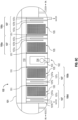
- FIG. 1A is a schematic diagram of an oil-water separation system 100.
- the oil-water separation system 100 includes a vessel 101.
- the vessel 101 includes a feed inlet distributor 102.
- the feed inlet distributor 102 includes an inlet pipe 103 and a housing 104.
- the oil-water separation system 100 includes a module 150, and an oil skimming trough 110, each of which are disposed within the vessel 101.
- the module 150 is disposed within the vessel 101 downstream of the feed inlet distributor 102 and includes multiple coalescer plates and a set of baffles 107.
- the set of baffles 107 is disposed within the vessel 101 downstream of the coalescer plates 105 and includes a first underflow baffle 107a, a second underflow baffle 107b, and an overflow baffle 107c.
- the coalescer plates 105 are configured to coalesce oil droplets together, and the set of baffles 107 is configured to disengage fluid flow to facilitate oil-water separation.
- the oil-water separation system 100 can include additional modules 150, such as two modules 150, three modules 150, or more than three modules 150.
- the modularity of the oil-water separation system 100 promotes de-oiling in stages.
- the module 150 includes a porous or perforated wall 151 directly upstream of the coalescer plates 105. The porous or perforated wall 151 is described in more detail later.
- FIG. 1B is a schematic diagram of the oil-water separation system 100 that includes a representation of fluid flow through the oil-water separation system 100.
- the velocity reduction and flow conditioning portion of the oil-water separation system 100 includes the feed inlet distributor 102.
- the droplet coalescing portion of the oil-water separation system 100 includes the coalescer plates 105.
- the oil disengagement and collection portion of the oil-water separation system 100 includes the baffles 107 and the oil skimming trough 110.
- a feed stream including oil and water flows to the oil-water separation system 100.
- the feed stream includes up to about 10 volume percent (vol. %) of oil.
- the inlet pipe 103 is configured to receive the feed stream.
- An outlet of the inlet pipe 103 is coupled to the housing 104.
- the feed stream flows through the inlet pipe 103 and into the housing 104.
- the feed inlet distributor 102 is configured to distribute the flow of the feed stream to facilitate separation of oil and water. In cases where the feed stream includes solid material, the solid material can fall out of the bottom of the housing 104 and stored (for example, in a solids receptacle) or disposed.
- the feed stream exits the housing 104 and flows through a porous or perforated plate to the module 150.
- the coalescer plates 150 are configured to facilitate coalescence of the oil.
- the oil may exist in the feed stream as oil droplets dispersed in the bulk water phase.
- the coalescer plates 105 promote the coalescence of these oil droplets. Because of gravity, lighter fluid (for example, oil) will tend to rise in relation to the denser fluid (for example, water). Therefore, the coalesced oil droplets will tend to rise within the vessel in relation to the water. In general, as fluid flows within the vessel 101, oil will tend to rise in relation to water, and the oil will accumulate in an upper fluid layer within the vessel 101.
- the coalescer plates 105 are described in more detail later.
- the first underflow baffle 107a is configured to direct fluid flow under the first underflow baffle 107a.
- the overflow baffle 107c is disposed between the first underflow baffle 107a and the second underflow baffle 107b.
- the overflow baffle 107c is configured to direct fluid flow over the overflow baffle 107c.
- the second underflow baffle 107b is configured to direct fluid flow under the second underflow baffle 107a.
- the tortuous flow path of the set of baffles 107 also facilitates separation of oil and water. Oil will tend to remain upstream of the first underflow baffle 107a because oil is less likely to flow under the first underflow baffle 107a in comparison to water. If, however, oil manages to flow with water under the first underflow baffle 107a, the oil will tend to remain as an upper layer in the stagnation region downstream of the first underflow baffle 107a and upstream of the second underflow baffle 107b.
- the set of baffles 107 is described in more detail later.
- the oil skimming trough 110 is configured to skim oil from an oil-water interface layer formed within the vessel 101. As oil accumulates in the upper fluid layer within the vessel 101, the oil skimming trough 110 skims oil from the upper fluid layer and discharges the oil from the vessel 101.
- the oil skimming trough 110 is described in more detail later.
- the module 150 includes a porous or perforated wall 151 directly upstream of the coalescer plates 105.
- the porous or perforated wall 151 includes pores, perforations, slots, mesh, or a combination of these.
- the porous or perforated wall 151 can facilitates separation of oil and water.
- the porous or perforated wall 151 can slow down the velocity of the fluid flowing within the vessel 101, which facilitates separation of oil and water.
- the oil-water separation system 100 includes additional porous or perforated walls 151 that can be disposed between two components of the oil-water separation system 100.
- an additional porous or perforated wall 151 can be disposed between the coalescer plates 105 and the set of baffles 107.
- the module 150 includes two porous or perforated walls 151 disposed directly upstream of the coalescer plates 105.
- the open flow areas of the two porous perforated walls 151 can be different from one another.
- the first porous or perforated wall 151 can have a larger open flow area, larger perforations, or both in comparison to the second porous or perforated wall 151.
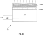
- FIG. 2A is a side view of the feed inlet distributor 102.
- the feed inlet distributor 102 includes multiple vanes 104a that are disposed within the housing 104.
- the housing 104 defines multiple perforations 104b.
- the vanes 104a are configured to direct flow of the feed stream to exit the housing 104 through the perforations 104b.
- the vanes 104a are vertical vanes.
- the vanes 104a deviate from the vertical (that is, are angled).
- some vanes 104a are vertical vanes, and some vanes 104a are angled.
- the vanes 104a prevent rotation (turbulence) in the flow and directs the fluid flow in a general upward direction toward the perforations 104b.
- the perforations 104b are located in an upper portion of the housing 102 with respect to gravity. Flow through the perforations 104b facilitates separation of the oil and the water in the feed stream.
- the perforations 104b have diameters that are in a range of from about 5 millimeters (mm) to about 60 mm.
- the perforations 104b can be uniform in diameter or vary in diameter.
- the total open flow area of the perforations 104b in comparison to a cross-sectional area of the housing 104 with respect to general flow direction is in a range of from about 10% to about 50%.
- the feed inlet distributor 102 is configured to be entirely submerged under the liquid level within the vessel 101.
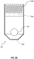
- FIG. 2B is a front view of the feed inlet distributor 102.
- a cross-sectional area of the housing 104 is larger than a cross-sectional area of the inlet pipe 103.
- the cross-sectional area of the housing 104 is at least double the cross-sectional area of the inlet pipe 103.
- the larger cross-sectional area of the housing 104 is configured to slow down the flow of the feed stream, thereby facilitating separation of the oil and the water.
- the housing 104 defines multiple perforations 104c in a lower portion of the housing 102 with respect to gravity.
- the perforations 104c have diameters that are in a range of from about 1 mm to about 10 mm.
- the perforations 104c can be uniform in diameter or vary in diameter. These perforations 104c allow for solid material that may be entrained in the feed stream to fall through the perforations 104c instead of accumulating within the housing 104.
- the outlet of the perforations 104c can be coupled to a solids receptacle or drain (an example is shown in FIGs. 1A and 1B ).
- FIG. 3A is a cross-sectional view of an implementation of the coalescer plates 105 disposed within the vessel 101.
- the coalescer plates 105 are mirrored across a centerline of the vessel 101.
- the coalescer plates 105 are parallel to one another.
- the coalescer plates 105 can be angled with respect to the centerline.
- the coalescer plates 105 are upwardly sloped with respect to gravity in a direction of fluid flow within the vessel 101.
- the angle ( ⁇ ) between each coalescer plate and the centerline is in a range of from about 30 degrees (°) to about 60°.
- the angle ( ⁇ ) between each coalescer plate and the centerline is 45°.
- the vertical spacing between neighboring coalescer plates is the same for all of the coalescer plates 105.
- the vertical spacing between neighboring coalescer plates can be selected based on various parameters, such as target size range of oil droplets for coalescing.
- the vertical spacing between neighboring coalescer plates varies in the coalescer plates 105. For example, starting from the bottommost coalescer plate, the vertical spacing between neighboring coalescer plates gradually decreases with each successive coalescer plate. For example, starting from the bottommost coalescer plate, the vertical spacing between neighboring coalescer plates gradually increases with each successive coalescer plate.
- the relationship between pressure drop of fluid flowing across the coalescer plates 105 is inversely proportional to the spacing between neighboring coalescer plates. For example, as the spacing between neighboring coalescer plates decreases, the pressure drop across the neighboring coalescer plates increases.
- FIG. 3B is a cross-sectional view of an implementation of the coalescer plates 105 disposed within the vessel 101.
- the coalescer plates 105 includes multiple rectangular units of coalescer plates distributed within the vessel 101.
- Each rectangular units of coalescer plates includes its own set of coalescer plates that are angled with respect to the centerline.
- each set of coalescer plates 105 include equally spaced (that is, vertically distributed evenly) coalescer plates.
- each set of coalescer plates 105 include coalescer plates that vary in vertical distribution.
- the vertical spacing between coalescer plates 105 is the same among the sets of coalescer plates.
- the vertical spacing between coalescer plates 105 vary among the sets of coalescer plates 105.
- a first set of coalescer plates 105 can include coalescer plates with 20 millimeter (mm) vertical spacing between adjacent coalescer plates
- a second set of coalescer plates 105 positioned above the first set of coalescer plates (within the vessel 101 with respect to gravity) can include coalescer plates with 40 mm vertical spacing between adjacent coalescer plates.
- the coalescer plates 105 in the configuration shown in FIG. 3B are mirrored across the centerline of the vessel 101.
- FIG. 3C shows a portion of the implementation shown in FIG. 3B , along with arrows representing general direction of fluid (oil) flow through the coalescer plates 105.
- FIG. 3D is a schematic diagram of an example configuration of multiple sets of coalescer plates 105.
- the sets of coalescer plates 105 are mounted to a lattice plate 106.
- the lattice plate 106 holds the sets of coalescer plates 105 in their separate locations and also prevents upstream flow of oil water disturbing oily water from rising between sets of coalescer plates 105.
- the lattice plate 106 can prevent ingress of water into the vertical channels between neighboring sets of coalescer plates 105.
- the lattice plate 106 prevents upstream fluid from interfering with oil droplet coalescence between horizontally adjacent sets of coalescer plates 105 with respect to the general direction of fluid flow within the vessel 101.
- FIG. 3E is a zoomed schematic view of an example oil droplet on a coalescer plate.
- the coalescer plates 105 are made from a metal, such as stainless steel or duplex stainless steel, or a polymer, such as polypropylene.
- the coalescer plates 105 are treated or formed of a material that makes the coalescer plates oleophobic and non-wetting to oil, such that the contact angle ( ⁇ ) between an oil droplet and a coalescer plate is greater than 90°. In some implementations, the contact angle ( ⁇ ) between an oil droplet and a coalescer plate is greater than 150°.
- the coalescer plates 105 include flat coalescer plates. In some implementations, the coalescer plates 105 include corrugated coalescer plates.
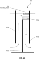
- FIG. 4A is a schematic diagram of an example set of baffles 107.
- the spacing between the first underflow baffle 107a and the overflow baffle 107c is substantially the same as the spacing between the overflow baffle 107c and the second underflow baffle 107b.
- the second underflow baffle 107b defines perforations.
- the second underflow baffle 107b can be in the form of a porous or perforated plate or an expanded metal screen.
- the second underflow baffle 107b defines vertical slots, horizontal slots, or both.
- the open flow area of the second underflow baffle 107b allows for fluid to flow under the second underflow baffle 107b or flow through the second underflow baffle 107b.
- Such open flow area can be implemented in the second underflow baffle 107b in implementations where longitudinal length of the vessel 101 is limited (for example, in retrofit applications).
- the baffles of the set of baffles 107 are made from a metal, such as stainless steel or duplex stainless steel, or a polymer, such as polypropylene.
- the baffles of the set of baffles 107 are treated or formed of a material that makes the set of baffles 107 oleophobic and non-wetting to oil, such that the contact angle between an oil droplet and a baffle (107a, 107b, or 107c) is greater than 90° (similar to the coalescer plates 105).
- the oil-water separation system 100 includes guide vanes 107d.
- the guide vanes 107d are disposed between the first underflow baffle 107a and the second underflow baffle 107b and also above the overflow baffle 107c.
- the guide vanes 107d are configured to be submerged below a liquid level within the vessel 101.
- the guide vanes 107d are submerged below the upper fluid layer of oil within the vessel 101.
- the guide vanes 107d span from the overflow baffle 107c to the second underflow baffle 107b.
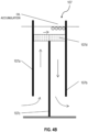
- FIG. 4B is a schematic diagram of an example set of baffles 107.
- the set of baffles 107 shown in FIG. 4B is substantially similar to the set of baffles 107 shown in FIG. 4A .
- the guide vanes 107d span from the first underflow baffle 107a to the second underflow baffle 107b.
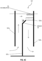
- FIG. 4C is a schematic diagram of an example set of baffles 107.
- the set of baffles 107 shown in FIG. 4C is substantially similar to the set of baffles 107 shown in FIG. 4A .
- the overflow baffle 107c includes an angled tip.
- the angled tip of the overflow baffle 107c has an angle ( ⁇ ) in a range of from 0° to 45° deviating from the vertical.
- the angled tip can increase the cross-sectional area for fluid flow and can also facilitate a reduction in fluid flow velocity as the fluid upwardly flows and approaches the liquid surface within the vessel 101.
- Flow deceleration can promote oil droplet disengagement and facilitate oil skimming. This is in contrast to straight baffles (0° deviation from the vertical) which can cause flow separation, wall detachment, formation of eddies, or a combination of these, all of which can disrupt oil droplet disengagement.
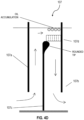
- FIG. 4D is a schematic diagram of an example set of baffles 107.
- the set of baffles 107 shown in FIG. 4D is substantially similar to the set of baffles 107 shown in FIG. 4A .
- the overflow baffle 107c includes a rounded tip. The rounded tip provides a smooth area transition to mitigate flow separation around the tip of the overflow baffle 107c and can facilitate smooth fluid flow to the guide vanes 107d.
- FIG. 4E is a schematic diagram of an example set of baffles 107.
- the set of baffles 107 shown in FIG. 4E is substantially similar to the set of baffles 1 07 shown in FIG. 4A .
- each of the first underflow baffle 107a, the second underflow baffle 107b, and the overflow baffle 107c include rounded tips. The rounded tips of the baffles 107 can facilitate smooth fluid flow around these baffles 107.
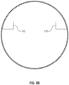
- FIG. 5A is a cross-sectional view of an implementation of the oil skimming trough 110.
- the oil-water separation system 100 can include multiple oil skimming troughs 110, for example, two oil skimming troughs 110.
- the oil skimming troughs 110 are downwardly sloped with respect to gravity toward an inner surface of the vessel 101.
- each oil skimming trough 110 includes curved portions that gradually slope toward the inner surface of the vessel 101.
- the oil skimming trough 110 can include an outlet near the bottom of the oil skimming trough 110 for discharging oil from the vessel 101. In some implementations, the outlet discharges to an oil collection reservoir located in a head of the vessel 101.
- each oil skimming trough 110 spans longitudinally within the vessel 101 over an area that covers (that is, overlaps with) the housing 104 and the module 150 (which includes the coalescer plates 105 and the set of baffles 107).
- the oil skimming trough 110 is made from a metal, such as stainless steel or duplex stainless steel, or a polymer, such as polypropylene.
- FIG. 5B is a cross-sectional view of an implementation of the oil skimming trough 110.
- the oil skimming troughs 110 of FIG. 5B are substantially similar to those of FIG. 5A , but have a different shape.
- FIG. 6A is a schematic diagram of an implementation of the oil-water separation system 100.
- the oil-water separation system 100 shown in FIG. 6A is substantially similar to the implementation shown in FIGs. 1A and 1B , but includes duplicates of some components.
- the oil-water separation system 100 in FIG. 6A includes multiple modules 150 (first module 150a and second module 150b).
- the second module 150b is downstream of the first module 150a.
- the oil-water separation system 100 can include additional modules 150, such as three or more modules 150.
- the oil-water separation system 100 can include additional feed inlet distributor(s) 102, additional oil skimming trough(s) 110, or both.
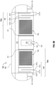
- FIG. 6B is a schematic diagram of an implementation of the oil-water separation system 100.
- the oil-water separation system 100 shown in FIG. 6B is substantially similar to the implementation shown in FIG. 6A , but the placement of various components vary.
- the oil-water separation system 100 in FIG. 6B includes multiple modules 150 (first module 150a and second module 150b) that are disposed at opposite sides of the feed inlet distributor 102.
- the second module 150b is not considered to be downstream of the first module 150a (as is the case for the oil-water separation system 100 in FIG. 6A ).
- the general flow of fluid through the oil-water separation system 100 in FIG. 6B is generally from the middle of the oil-water separation system 100 out to the sides.
- the oil-water separation system 100 can include additional modules 150, such as three or more modules 150.
- additional modules 150 such as three or more modules 150.
- the oil-water separation system 100 can include additional feed inlet distributor(s) 102, additional oil skimming trough(s) 110, or both.
- FIG. 6C is a schematic diagram of an implementation of the oil-water separation system 100.
- the oil-water separation system 100 shown in FIG. 6C is substantially similar to the implementations shown in FIG. 6B , but includes duplicates of some components.
- the oil-water separation system 100 can include a third module 150c downstream of first module 150a and a fourth module 150d downstream of the second module 150b.
- about half of the fluid entering the oil-water separation system 100 would flow through the first module 150a and then the third module 150c, and the other half of the fluid entering the oil-water separation system 100 would flow through the second module 150b and then the fourth module 150d.
- the oil-water separation system 100 can include additional modules 150, such as five or more modules 150. The same applies to any of the aforementioned components of the oil-water separation system 100. That is, the oil-water separation system 100 can include additional feed inlet distributor(s) 102, additional oil skimming trough(s) 110, or both.
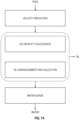
- FIG. 7A is a flow chart representing the flow and functions of the oil-water separation system 100.
- a feed stream including oil and water is flowed to the oil-water separation system 100.
- the feed stream can include, for example, oil droplets dispersed in a bulk water phase. In some implementations, the feed stream includes up to 10 vol. % of oil.
- the velocity of the feed stream is reduced, for example, by the feed inlet distributor 102.
- the oil droplets are coalesced, for example, by the coalescer plates 105.
- the oil is disengaged and collected, for example, by the set of baffles 107 and the oil skimming trough 110. The collected oil is discharged from the oil-water separation system 100.
- the oil-water separation system 100 can include a surge compartment for holding the water separated from the feed stream.
- the surge compartment can be located within the vessel 101 downstream of the module 150. In implementations that include multiple modules 150, the surge compartment can be located downstream of the final module 150 with respect to the general direction of fluid flow through the vessel 101.
- the water can be discharged from the oil-water separation system 100. In some implementations, the water discharged from the oil-water separation system 100 has an oil concentration that is less than 100 ppm. In some implementations, the water discharged from the oil-water separation system 100 has an oil concentration that is less than 50 ppm.
- FIG. 7B is a flow chart of an example method 700 for phase separation.
- the method 700 can be implemented by the oil-water separation system 100.
- a feed stream including oil and water is received by an inlet pipe, for example, the inlet pipe 103 of the feed inlet distributor 102.
- the feed stream is discharged from an outlet of the inlet pipe 103 into a housing, for example, the housing 104 of the feed inlet distributor 102.
- the housing 104 is disposed within the vessel 101 and has a cross-sectional area that is larger than the cross-sectional area of the inlet pipe 103 in relation to the direction of fluid flow.
- the feed stream is directed by vanes, for example, the vanes 104a, to exit the housing 104 through perforations defined by the housing 104, for example, the perforations 104b.
- the vanes 104a are disposed within the housing 104.
- coalescing the oil droplets by coalescer plates for example, the coalescer plates 105 disposed within the vessel 101 downstream of the housing 104.
- the coalescer plates 105 receive the oil droplets, and the oil droplets coalesce together while traveling across the surfaces of the coalescer plates 105.
- Step 710 directing the coalesced oil droplets in an upwardly sloped direction that opposes gravity. Step 710 can be performed by the coalescer plates of the first module 105.
- fluid flow is directed under a baffle, for example, the first underflow baffle 107a disposed within the vessel 101 downstream of the coalescer plates 105.
- fluid flow is directed over a baffle, for example, the overflow baffle 107c disposed within the vessel 101 downstream of the first underflow baffle 107a.
- fluid flow is directed under a baffle, for example, the second underflow baffle 107b disposed within the vessel 101 downstream of the overflow baffle 107c.
- a portion of the fluid flow is directed through the second underflow baffle 107b, for example, where the second underflow baffle 107b has open flow area (such as perforations, slots, or both).
- steps 708, 710, 712, 714, and 716 are repeated based on the number of modules 150 present within the oil-water separation system 100. For example, steps 708, 710, 712, 714, and 716 are repeated for each additional module 150 present within the oil-water separation system 100. Each progression of steps 708, 710, 712, 714, and 716 can be considered a progression through a module 150 of oil-water separation within the oil-water separation system 100.
- the coalesced oil droplets are directed toward an inner surface of the vessel 101, for example, by the oil skimming trough 110 that is disposed within the vessel 101 and downwardly sloped with respect to gravity toward the inner surface of the vessel 101.
- the water (separated from the feed stream) is discharged from the vessel 101.
- the water discharged from the vessel 101 at step 720 has an oil concentration that is less than 100 ppm. In some implementations, the water discharged from the vessel 101 at step 720 has an oil concentration that is about 50 ppm.
- Any step of method 700 can occur simultaneously with any of the other steps of method 700. Any step of method 700 can be repeated to achieve a desired level of oil-water separation within the oil-water separation system 100.
- the term "about” or “approximately” can allow for a degree of variability in a value or range, for example, within 10%, within 5%, or within 1% of a stated value or of a stated limit of a range.
- the term “substantially” refers to a majority of, or mostly, as in at least about 50%, 60%, 70%, 80%, 90%, 95%, 96%, 97%, 98%, 99%, 99.5%, 99.9%, 99.99%, or at least about 99.999% or more.
Landscapes
- Chemical & Material Sciences (AREA)
- Physics & Mathematics (AREA)
- Thermal Sciences (AREA)
- Chemical Kinetics & Catalysis (AREA)
- Hydrology & Water Resources (AREA)
- Life Sciences & Earth Sciences (AREA)
- Analytical Chemistry (AREA)
- Engineering & Computer Science (AREA)
- Environmental & Geological Engineering (AREA)
- Water Supply & Treatment (AREA)
- Organic Chemistry (AREA)
- Removal Of Floating Material (AREA)
- Separating Particles In Gases By Inertia (AREA)
Claims (13)
- Système (100) de séparation huile-eau, comprenant :une cuve (101) comprenant un distributeur d'entrée d'alimentation (102), le distributeur d'entrée d'alimentation comprenantun tuyau d'entrée (103) configuré pour être accouplé de manière à recevoir un flux d'alimentation comprenant de l'huile et de l'eau,un carter (104), une sortie du tuyau d'entrée étant accouplée au carter, une section transversale du carter étant plus grande qu'une section transversale du tuyau d'entrée par rapport à l'écoulement du flux d'alimentation, la section transversale plus grande du carter étant configurée pour ralentir l'écoulement du flux d'alimentation, pour ainsi faciliter la séparation de l'huile et de l'eau ; au cours de l'écoulement du flux d'alimentation à travers le système, le distributeur d'entrée d'alimentation étant submergé au-dessous du niveau de liquide à l'intérieur de la cuve, etune pluralité d'aubes (104a) agencées à l'intérieur du carter, les aubes étant verticales ou inclinées, le carter définissant une pluralité de perforations (104b), et la pluralité d'aubes étant configurées pour guider l'écoulement du flux d'alimentation de manière à le faire sortir du carter à travers la pluralité de perforations ; un module (150) agencé à l'intérieur de la cuve en aval du distributeur d'entrée d'alimentation, le module comprenantune pluralité de plaques de coalescence (105), la pluralité de plaques de coalescence étant configurées pour faciliter la coalescence de l'huile,une paroi poreuse ou perforée (151) agencée à l'intérieur de la cuve entre le distributeur d'entrée d'alimentation et la pluralité de plaques de coalescence,un premier déflecteur de sousverse (107a), le premier déflecteur de sousverse étant configuré pour guider un écoulement fluidique sous le premier déflecteur de sousverse,un deuxième déflecteur de sousverse (107b) en aval du premier déflecteur de sousverse, le deuxième déflecteur de sousverse définissant une deuxième pluralité de perforations, le deuxième déflecteur de sousverse étant configuré pour guider un écoulement fluidique sous le deuxième déflecteur de sousverse et à travers la deuxième pluralité de perforations, etun déflecteur de surverse (107c) agencé entre le premier et le deuxième déflecteur de sousverse ; au cours de l'écoulement du flux d'alimentation à travers le système, le déflecteur de surverse étant submergé au-dessous d'un niveau de liquide à l'intérieur de la cuve et guidant un écoulement fluidique par-dessus le déflecteur de surverse ;une auge d'écrémage de l'huile (110) agencée à l'intérieur de la cuve, l'auge d'écrémage de l'huile s'étendant longitudinalement de part en part de la cuve et étant inclinée vers le bas par rapport à la gravité en direction d'une surface intérieure de la cuve, l'auge d'écrémage de l'huile étant configurée pour écrémer l'huile d'une couche d'interface huile-eau formée à l'intérieur de la cuve ; etune sortie d'eau.
- Système selon la revendication 1, comprenant une pluralité de modules, chacun des modules de la pluralité de modules étant espacé longitudinalement des autres à l'intérieur de la cuve, et
facultativement chacune des plaques de coalescence de la pluralité des plaques de coalescence étant parallèle aux autres et inclinée vers le haut par rapport à la gravité. - Système selon la revendication 1, le premier déflecteur de sousverse et/ou le deuxième déflecteur de sousverse et/ou le déflecteur de surverse comprenant un bout arrondi.
- Système selon la revendication 1, un espacement entre le premier déflecteur de sousverse et le déflecteur de surverse étant sensiblement identique à un espacement entre le déflecteur de surverse et le deuxième déflecteur de sousverse.
- Système selon la revendication 1, comprenant une pluralité d'aubes directrices agencées entre le premier et le deuxième déflecteur de sousverse et au-dessus du déflecteur de surverse par rapport à la gravité ; au cours de l'écoulement du flux d'alimentation à travers le système, la pluralité d'aubes directrices étant submergées au-dessous du niveau de liquide à l'intérieur de la cuve.
- Système selon la revendication 5, la pluralité d'aubes directrices s'étendant soit depuis le déflecteur de surverse soit depuis le premier déflecteur de sousverse jusqu'au deuxième déflecteur de sousverse.
- Système selon la revendication 1, la sortie du tuyau d'entrée étant accouplée à une partie inférieure du carter du distributeur d'entrée d'alimentation, et la pluralité de perforations définies par le carter du distributeur d'entrée d'alimentation étant situées sur une partie supérieure du carter du distributeur d'entrée d'alimentation.
- Système selon la revendication 1, l'auge d'écrémage de l'huile s'étendant longitudinalement de part en part de la cuve sur une zone qui couvre le carter du distributeur d'entrée d'alimentation et le module.
- Système selon la revendication 1, la paroi poreuse ou perforée se situant directement en amont de la pluralité de plaques de coalescence, le module étant un premier module, et le système comprenant un deuxième module agencé à l'intérieur de la cuve en aval du premier module, le deuxième module étant sensiblement identique au premier module, et l'auge d'écrémage de l'huile s'étendant longitudinalement de part en part de la cuve sur une zone qui couvre le carter du distributeur d'entrée d'alimentation, le premier module, et le deuxième module.
- Système selon la revendication 1, la pluralité de plaques de coalescence étant ondulées et, pour chacune des plaques de coalescence de la pluralité de plaques de coalescence, un angle de contact entre une gouttelette d'huile et une surface de la plaque de coalescence respective étant supérieur à 90 degrés.
- Procédé, comprenant :la réception (702), par un tuyau d'entrée, d'un flux d'alimentation comprenant de l'huile et de l'eau ;le rejet (704), par une sortie du tuyau d'entrée, du flux d'alimentation jusque dans un carter pourvu d'une section transversale plus grande qu'une section transversale du tuyau d'entrée par rapport à une direction d'écoulement fluidique, le carter étant agencé à l'intérieur d'une cuve et submergé au-dessous du niveau de liquide à l'intérieur de la cuve ;le guidage (706), par une pluralité d'aubes agencées à l'intérieur du carter, du flux d'alimentation de manière à le faire sortir du carter à travers une pluralité de perforations définies par le carter ;l'écoulement du flux d'alimentation à travers une plaque poreuse ou perforée ;par un module agencé à l'intérieur de la cuve en aval du carter,la coalescence (708), par une pluralité de plaques de coalescence du module, de gouttelettes d'huile de l'huile ; etle guidage (710), par la pluralité de plaques de coalescence, des gouttelettes d'huile qui ont coalescé dans une direction inclinée vers le haut opposée à la gravité ;le guidage (712), par un premier déflecteur de sousverse du module, d'un écoulement fluidique sous le premier déflecteur de sousverse ;le guidage (714), par un déflecteur de surverse du module, d'un écoulement fluidique par-dessus le déflecteur de surverse, le déflecteur de surverse étant situé en aval du premier déflecteur de sousverse ; etle guidage (716), par un deuxième déflecteur de sousverse du module, d'un écoulement fluidique sous le deuxième déflecteur de sousverse et à travers une deuxième pluralité de perforations, le deuxième déflecteur de sousverse étant situé en aval du déflecteur de surverse et le deuxième déflecteur de sousverse définissant la deuxième pluralité de perforations ;le guidage (718), par une auge d'écrémage de l'huile agencée à l'intérieur de la cuve, s'étendant longitudinalement de part en part de la cuve, et inclinée vers le bas par rapport à la gravité en direction d'une surface intérieure de la cuve, des gouttelettes d'huile qui ont coalescé en direction de la surface intérieure de la cuve ; etle rejet (720) de l'eau de la cuve.
- Procédé selon la revendication 11, le flux d'alimentation comprenant jusqu'à 10 % en volume d'huile.
- Procédé selon la revendication 12, l'eau rejetée de la cuve présentant une concentration d'huile inférieure à 50 parties par million, et
facultativement la coalescence des gouttelettes d'huile comprenant la réception des gouttelettes d'huile par la pluralité de plaques de coalescence, et la coalescence des gouttelettes d'huile tandis qu'elles traversent la pluralité de plaques de coalescence.
Applications Claiming Priority (2)
| Application Number | Priority Date | Filing Date | Title |
|---|---|---|---|
| US16/912,429 US11090581B1 (en) | 2020-06-25 | 2020-06-25 | Oil and water separation |
| PCT/US2021/038946 WO2021263017A1 (fr) | 2020-06-25 | 2021-06-24 | Séparation d'huile et d'eau |
Publications (2)
| Publication Number | Publication Date |
|---|---|
| EP4171776A1 EP4171776A1 (fr) | 2023-05-03 |
| EP4171776B1 true EP4171776B1 (fr) | 2024-07-31 |
Family
ID=77022229
Family Applications (1)
| Application Number | Title | Priority Date | Filing Date |
|---|---|---|---|
| EP21745528.6A Active EP4171776B1 (fr) | 2020-06-25 | 2021-06-24 | Séparation d'huile et d'eau |
Country Status (6)
| Country | Link |
|---|---|
| US (1) | US11090581B1 (fr) |
| EP (1) | EP4171776B1 (fr) |
| KR (1) | KR20230029835A (fr) |
| CN (1) | CN115867369B (fr) |
| SA (1) | SA522441868B1 (fr) |
| WO (1) | WO2021263017A1 (fr) |
Families Citing this family (8)
| Publication number | Priority date | Publication date | Assignee | Title |
|---|---|---|---|---|
| US11939233B2 (en) | 2021-12-10 | 2024-03-26 | Saudi Arabian Oil Company | Oil-water separation system using hydrophobic/hydrophilic materials for capacity increase and improving produced water quality |
| CA3255523A1 (fr) * | 2022-03-31 | 2023-10-05 | Arxada Switzerland AG | Gestion de la teneur en eau et de la qualité de produits de conservation du bois à base d'huile |
| CN118079459A (zh) * | 2022-11-25 | 2024-05-28 | 中国石油化工股份有限公司 | 一种具有油水分离功能的真空液封罐及控制系统 |
| US12678712B2 (en) * | 2022-11-28 | 2026-07-14 | Zenrg Services, Llc | Methods to drawdown pipe sections with the use or regulation control of flaring and cross-compression technique |
| KR102881676B1 (ko) * | 2023-03-31 | 2025-11-05 | 주식회사 쉐코 | 카트리지를 포함하는 수면 부유층 제거 장치 |
| CN119793008A (zh) * | 2023-10-09 | 2025-04-11 | 中国石油化工股份有限公司 | 液液分离和缓冲装置 |
| CN119455460B (zh) * | 2024-11-05 | 2025-11-07 | 中国华能集团清洁能源技术研究院有限公司 | 分相器 |
| CN119186028B (zh) * | 2024-11-27 | 2025-03-14 | 中国计量大学 | 一种用于危化品混合物安全高效分离的液液分离器 |
Family Cites Families (57)
| Publication number | Priority date | Publication date | Assignee | Title |
|---|---|---|---|---|
| BE358284A (fr) * | 1926-12-20 | |||
| NL6801614A (fr) * | 1968-02-05 | 1969-08-07 | ||
| US3853753A (en) * | 1970-10-13 | 1974-12-10 | Amoco Prod Co | Removing oil from waste water with sulfur |
| US3957656A (en) | 1972-04-28 | 1976-05-18 | Castelli Joseph L | Plate separator for fluid mixtures |
| US3951810A (en) | 1973-02-06 | 1976-04-20 | Crisafulli Angelo J | Oil skimmer module with free floating weir trough |
| US4123365A (en) * | 1974-08-14 | 1978-10-31 | Ballast-Nedam Groep N.V. | Oil-water separator |
| US4120797A (en) | 1977-03-01 | 1978-10-17 | Huebner Werner P E | Cross-flow inclined plate clarifier |
| US4081373A (en) | 1977-05-26 | 1978-03-28 | The United States Of America As Represented By The Secretary Of The Army | Mechanism for exhausting impurities from engine fuel |
| AU536655B2 (en) | 1979-04-11 | 1984-05-17 | British Petroleum Company Limited, The | m |
| US4278545A (en) * | 1979-09-12 | 1981-07-14 | The Bendix Corporation | Apparatus for separating solids and liquid components |
| US4479875A (en) | 1983-08-31 | 1984-10-30 | Kerr-Mcgee Refining Corporation | Inlet distributor for liquid-liquid separators |
| US4581134A (en) | 1984-09-28 | 1986-04-08 | Texaco Inc. | Crude oil dehydrator/desalter control system |
| US4722800A (en) | 1986-05-30 | 1988-02-02 | Highland Tank And Manufacturing Company | Oil-water separator |
| DE3841198A1 (de) * | 1988-12-07 | 1990-06-13 | Ossenkop Maschinenbau | Vorrichtung zur oelabscheidung |
| US5068035A (en) | 1991-01-28 | 1991-11-26 | Facet Quantek, Inc. | Coalescing plate packing system |
| US5242604A (en) | 1992-01-10 | 1993-09-07 | Sudden Service Co. | Lateral flow coalescing multiphase plate separator |
| US5204000A (en) * | 1992-01-31 | 1993-04-20 | Zcl Mfg Canada Inc. | Tank for separating water and hydrocarbon fuels from contaminated water |
| JP2560687Y2 (ja) * | 1992-03-31 | 1998-01-26 | トリニティ工業株式会社 | 廃液処理槽 |
| US5443724A (en) | 1992-12-23 | 1995-08-22 | Pall Corporation | Apparatus for separating the components of a liquid/liquid mixture |
| US5520825A (en) * | 1993-11-08 | 1996-05-28 | Mctighe Industries, Inc. | Oil-water separator |
| US5762810A (en) * | 1996-11-22 | 1998-06-09 | Pelton; Paul | Coalescing oil/water separator |
| CA2252307C (fr) * | 1998-05-15 | 2004-03-02 | James Richard George Stowell | Separateur eau/huile |
| GB9902220D0 (en) | 1999-02-01 | 1999-03-24 | Cyclotech Limited | Fluid processing |
| BR0008743B1 (pt) * | 1999-03-05 | 2010-02-09 | separador de trÊs fases, e, processo para separar uma mistura de gÁs, àleo e Água nos constituintes gÁs, àleo e Água. | |
| US6338684B1 (en) | 1999-10-14 | 2002-01-15 | Acushnet Company | Phyllotaxis-based dimple patterns |
| GB2374818B (en) | 2001-04-23 | 2005-01-12 | Secr Defence | Surface for promoting droplet formation |
| US6843832B2 (en) | 2001-06-14 | 2005-01-18 | Boyd B. Greene | Compound/curvilinear immiscible liquid separator apparatus and method |
| US6605224B2 (en) * | 2001-07-24 | 2003-08-12 | Highland Tank And Manufacturing Company | Coalescer apparatus in an oil/water separator |
| US7044308B2 (en) | 2002-06-05 | 2006-05-16 | Allan Clarke Benson | Apparatus for the removal of suspended solids and entrained oil from an aqueous solution |
| CN2566925Y (zh) | 2002-08-10 | 2003-08-20 | 林国雄 | 一种油水分离装置 |
| US6907997B2 (en) * | 2003-02-19 | 2005-06-21 | Hancor, Inc. | Water clarification system with coalescing plates |
| EA011658B1 (ru) | 2004-01-20 | 2009-04-28 | М-И Эпкон Ас | Установка для начального разделения текучей среды в устье скважины |
| US7118670B2 (en) * | 2004-04-20 | 2006-10-10 | Edmondson Jerry M | Energy efficient compact oil and water separator |
| US20060078724A1 (en) | 2004-10-07 | 2006-04-13 | Bharat Bhushan | Hydrophobic surface with geometric roughness pattern |
| US8057567B2 (en) | 2004-11-05 | 2011-11-15 | Donaldson Company, Inc. | Filter medium and breather filter structure |
| US8114183B2 (en) | 2005-09-20 | 2012-02-14 | Cummins Filtration Ip Inc. | Space optimized coalescer |
| US8231752B2 (en) | 2005-11-14 | 2012-07-31 | Cummins Filtration Ip Inc. | Method and apparatus for making filter element, including multi-characteristic filter element |
| US8080158B2 (en) | 2005-11-22 | 2011-12-20 | Exterran Water Solutions Ulc | Vessel and method for treating contaminated water |
| US20080011693A1 (en) | 2006-07-12 | 2008-01-17 | Ming Li | Self-cleaning waste-water device and method |
| US9199185B2 (en) | 2009-05-15 | 2015-12-01 | Cummins Filtration Ip, Inc. | Surface coalescers |
| US20100326922A1 (en) | 2009-06-26 | 2010-12-30 | General Electric Company | Oil water separation apparatus |
| US8337603B2 (en) | 2010-04-12 | 2012-12-25 | Saudi Arabian Oil Company | Apparatus for separation of gas-liquid mixtures and promoting coalescence of liquids |
| CN101857286A (zh) | 2010-06-29 | 2010-10-13 | 哈尔滨工业大学水资源国家工程研究中心有限公司 | 折板聚结除油填料 |
| IT1404151B1 (it) | 2010-12-29 | 2013-11-15 | Eni Spa | Apparato di separazione per coalescenza di una miscela comprendente due fasi fluide tra loro immiscibili e di diversa densita' specifica |
| US9181499B2 (en) | 2013-01-18 | 2015-11-10 | Ecolab Usa Inc. | Systems and methods for monitoring and controlling desalting in a crude distillation unit |
| TWI589404B (zh) | 2013-06-28 | 2017-07-01 | 聖高拜磨料有限公司 | 基於向日葵圖案之經塗佈的研磨製品 |
| US9573079B2 (en) | 2013-10-31 | 2017-02-21 | General Electric Company | Article and apparatus for enhancing the coalescence of a dispersed phase from a continuous phase in an emulsion |
| JP6465272B2 (ja) * | 2013-11-18 | 2019-02-06 | 東洋エンジニアリング株式会社 | 油水分離器、油水分離方法、およびろ過膜ユニット |
| US8985343B1 (en) | 2014-01-24 | 2015-03-24 | Kirby Smith Mohr | Method and apparatus for separating immiscible liquids and solids from liquids |
| US9157035B1 (en) | 2014-03-04 | 2015-10-13 | High-Tech Consultants, Inc. | Local produced oil dehydrator |
| WO2015143155A1 (fr) | 2014-03-21 | 2015-09-24 | 3M Innovative Properties Company | Coalesceurs de gouttelettes |
| CN104876298A (zh) | 2015-05-28 | 2015-09-02 | 江苏瑞吉格泰油气工程有限公司 | 分离器的双锥平行液-液聚结板填料 |
| US9833727B1 (en) | 2015-11-24 | 2017-12-05 | Breakthrough Engenuity, Llc | Oilfield treatment vessel for removing water from oil |
| EP3255370B1 (fr) | 2016-06-06 | 2019-12-04 | Aerco International, Inc. | Échangeur de chaleur radial optimisé de fibonacci |
| US10370599B2 (en) | 2017-01-06 | 2019-08-06 | Saudi Arabian Oil Company | Methods and systems for optimizing demulsifier and wash water injection rates in gas oil separation plants |
| US10513913B2 (en) | 2017-06-22 | 2019-12-24 | Saudi Arabian Oil Company | Controlling high-pressure production trap separation efficiency |
| CN209721650U (zh) * | 2018-11-30 | 2019-12-03 | 中科合成油工程股份有限公司 | 油水分离器 |
-
2020
- 2020-06-25 US US16/912,429 patent/US11090581B1/en active Active
-
2021
- 2021-06-24 WO PCT/US2021/038946 patent/WO2021263017A1/fr not_active Ceased
- 2021-06-24 CN CN202180045303.3A patent/CN115867369B/zh active Active
- 2021-06-24 EP EP21745528.6A patent/EP4171776B1/fr active Active
- 2021-06-24 KR KR1020237002389A patent/KR20230029835A/ko active Pending
-
2022
- 2022-12-22 SA SA522441868A patent/SA522441868B1/ar unknown
Also Published As
| Publication number | Publication date |
|---|---|
| EP4171776A1 (fr) | 2023-05-03 |
| CN115867369B (zh) | 2026-06-16 |
| US11090581B1 (en) | 2021-08-17 |
| WO2021263017A1 (fr) | 2021-12-30 |
| KR20230029835A (ko) | 2023-03-03 |
| SA522441868B1 (ar) | 2024-07-12 |
| CN115867369A (zh) | 2023-03-28 |
Similar Documents
| Publication | Publication Date | Title |
|---|---|---|
| US11090581B1 (en) | Oil and water separation | |
| US5173195A (en) | Phase separator module | |
| US4802978A (en) | Oil-water separator | |
| US4333835A (en) | Vertical tube liquid pollutant separators | |
| US8470080B1 (en) | High pressure separator | |
| EP3458174B1 (fr) | Ensemble de filtration et procédé de filtration | |
| JPH04247283A (ja) | 液体浄化装置 | |
| CN202400880U (zh) | 一种二级聚结处理含油污水的装置 | |
| EP1735070B1 (fr) | Dispositif separateur | |
| RU2641926C2 (ru) | Резервуар для газовой флотации | |
| US9174223B2 (en) | Compact separation apparatus | |
| CN112169377A (zh) | 一种破乳填料及包含破乳填料的卧式油水分离过滤器 | |
| GB2116447A (en) | Phase separation device | |
| CN119320189B (zh) | 油田水处理填料及装置 | |
| US4720341A (en) | Water treating in a vertical series coalescing flume | |
| CN212609679U (zh) | 一种连续聚结与分离器和连续聚结除油装置 | |
| US5108609A (en) | Treatment of liquids | |
| US11939233B2 (en) | Oil-water separation system using hydrophobic/hydrophilic materials for capacity increase and improving produced water quality | |
| KR100230914B1 (ko) | 수면접촉식 유수분리장치 | |
| US5340470A (en) | Phase separator apparatus | |
| CN214019335U (zh) | 一种破乳填料及包含破乳填料的卧式油水分离过滤器 | |
| KR100869312B1 (ko) | 오수 부상분리처리조 | |
| EP1850937A1 (fr) | Séparateur d'huile | |
| CN113800592B (zh) | 一种连续聚结与分离器和连续聚结除油装置 | |
| CN119191460A (zh) | 一种能够减少占地面积的油田采出水预分离方法及装置 |
Legal Events
| Date | Code | Title | Description |
|---|---|---|---|
| STAA | Information on the status of an ep patent application or granted ep patent |
Free format text: STATUS: UNKNOWN |
|
| STAA | Information on the status of an ep patent application or granted ep patent |
Free format text: STATUS: THE INTERNATIONAL PUBLICATION HAS BEEN MADE |
|
| PUAI | Public reference made under article 153(3) epc to a published international application that has entered the european phase |
Free format text: ORIGINAL CODE: 0009012 |
|
| STAA | Information on the status of an ep patent application or granted ep patent |
Free format text: STATUS: REQUEST FOR EXAMINATION WAS MADE |
|
| 17P | Request for examination filed |
Effective date: 20230117 |
|
| AK | Designated contracting states |
Kind code of ref document: A1 Designated state(s): AL AT BE BG CH CY CZ DE DK EE ES FI FR GB GR HR HU IE IS IT LI LT LU LV MC MK MT NL NO PL PT RO RS SE SI SK SM TR |
|
| P01 | Opt-out of the competence of the unified patent court (upc) registered |
Effective date: 20230616 |
|
| DAV | Request for validation of the european patent (deleted) | ||
| DAX | Request for extension of the european patent (deleted) | ||
| STAA | Information on the status of an ep patent application or granted ep patent |
Free format text: STATUS: EXAMINATION IS IN PROGRESS |
|
| 17Q | First examination report despatched |
Effective date: 20231207 |
|
| GRAP | Despatch of communication of intention to grant a patent |
Free format text: ORIGINAL CODE: EPIDOSNIGR1 |
|
| STAA | Information on the status of an ep patent application or granted ep patent |
Free format text: STATUS: GRANT OF PATENT IS INTENDED |
|
| INTG | Intention to grant announced |
Effective date: 20240502 |
|
| GRAS | Grant fee paid |
Free format text: ORIGINAL CODE: EPIDOSNIGR3 |
|
| GRAA | (expected) grant |
Free format text: ORIGINAL CODE: 0009210 |
|
| STAA | Information on the status of an ep patent application or granted ep patent |
Free format text: STATUS: THE PATENT HAS BEEN GRANTED |
|
| AK | Designated contracting states |
Kind code of ref document: B1 Designated state(s): AL AT BE BG CH CY CZ DE DK EE ES FI FR GB GR HR HU IE IS IT LI LT LU LV MC MK MT NL NO PL PT RO RS SE SI SK SM TR |
|
| REG | Reference to a national code |
Ref country code: CH Ref legal event code: EP Ref country code: GB Ref legal event code: FG4D |
|
| REG | Reference to a national code |
Ref country code: DE Ref legal event code: R096 Ref document number: 602021016525 Country of ref document: DE |
|
| REG | Reference to a national code |
Ref country code: IE Ref legal event code: FG4D |
|
| REG | Reference to a national code |
Ref country code: LT Ref legal event code: MG9D |
|
| REG | Reference to a national code |
Ref country code: NL Ref legal event code: MP Effective date: 20240731 |
|
| PG25 | Lapsed in a contracting state [announced via postgrant information from national office to epo] |
Ref country code: PT Free format text: LAPSE BECAUSE OF FAILURE TO SUBMIT A TRANSLATION OF THE DESCRIPTION OR TO PAY THE FEE WITHIN THE PRESCRIBED TIME-LIMIT Effective date: 20241202 |
|
| REG | Reference to a national code |
Ref country code: AT Ref legal event code: MK05 Ref document number: 1707946 Country of ref document: AT Kind code of ref document: T Effective date: 20240731 |
|
| PG25 | Lapsed in a contracting state [announced via postgrant information from national office to epo] |
Ref country code: PT Free format text: LAPSE BECAUSE OF FAILURE TO SUBMIT A TRANSLATION OF THE DESCRIPTION OR TO PAY THE FEE WITHIN THE PRESCRIBED TIME-LIMIT Effective date: 20241202 |
|
| PG25 | Lapsed in a contracting state [announced via postgrant information from national office to epo] |
Ref country code: NL Free format text: LAPSE BECAUSE OF FAILURE TO SUBMIT A TRANSLATION OF THE DESCRIPTION OR TO PAY THE FEE WITHIN THE PRESCRIBED TIME-LIMIT Effective date: 20240731 Ref country code: PL Free format text: LAPSE BECAUSE OF FAILURE TO SUBMIT A TRANSLATION OF THE DESCRIPTION OR TO PAY THE FEE WITHIN THE PRESCRIBED TIME-LIMIT Effective date: 20240731 Ref country code: FI Free format text: LAPSE BECAUSE OF FAILURE TO SUBMIT A TRANSLATION OF THE DESCRIPTION OR TO PAY THE FEE WITHIN THE PRESCRIBED TIME-LIMIT Effective date: 20240731 Ref country code: GR Free format text: LAPSE BECAUSE OF FAILURE TO SUBMIT A TRANSLATION OF THE DESCRIPTION OR TO PAY THE FEE WITHIN THE PRESCRIBED TIME-LIMIT Effective date: 20241101 |
|
| PG25 | Lapsed in a contracting state [announced via postgrant information from national office to epo] |
Ref country code: BG Free format text: LAPSE BECAUSE OF FAILURE TO SUBMIT A TRANSLATION OF THE DESCRIPTION OR TO PAY THE FEE WITHIN THE PRESCRIBED TIME-LIMIT Effective date: 20240731 |
|
| PG25 | Lapsed in a contracting state [announced via postgrant information from national office to epo] |
Ref country code: LV Free format text: LAPSE BECAUSE OF FAILURE TO SUBMIT A TRANSLATION OF THE DESCRIPTION OR TO PAY THE FEE WITHIN THE PRESCRIBED TIME-LIMIT Effective date: 20240731 |
|
| PG25 | Lapsed in a contracting state [announced via postgrant information from national office to epo] |
Ref country code: IS Free format text: LAPSE BECAUSE OF FAILURE TO SUBMIT A TRANSLATION OF THE DESCRIPTION OR TO PAY THE FEE WITHIN THE PRESCRIBED TIME-LIMIT Effective date: 20241130 Ref country code: AT Free format text: LAPSE BECAUSE OF FAILURE TO SUBMIT A TRANSLATION OF THE DESCRIPTION OR TO PAY THE FEE WITHIN THE PRESCRIBED TIME-LIMIT Effective date: 20240731 |
|
| PG25 | Lapsed in a contracting state [announced via postgrant information from national office to epo] |
Ref country code: HR Free format text: LAPSE BECAUSE OF FAILURE TO SUBMIT A TRANSLATION OF THE DESCRIPTION OR TO PAY THE FEE WITHIN THE PRESCRIBED TIME-LIMIT Effective date: 20240731 |
|
| PG25 | Lapsed in a contracting state [announced via postgrant information from national office to epo] |
Ref country code: RS Free format text: LAPSE BECAUSE OF FAILURE TO SUBMIT A TRANSLATION OF THE DESCRIPTION OR TO PAY THE FEE WITHIN THE PRESCRIBED TIME-LIMIT Effective date: 20241031 Ref country code: ES Free format text: LAPSE BECAUSE OF FAILURE TO SUBMIT A TRANSLATION OF THE DESCRIPTION OR TO PAY THE FEE WITHIN THE PRESCRIBED TIME-LIMIT Effective date: 20240731 |
|
| PG25 | Lapsed in a contracting state [announced via postgrant information from national office to epo] |
Ref country code: RS Free format text: LAPSE BECAUSE OF FAILURE TO SUBMIT A TRANSLATION OF THE DESCRIPTION OR TO PAY THE FEE WITHIN THE PRESCRIBED TIME-LIMIT Effective date: 20241031 Ref country code: PL Free format text: LAPSE BECAUSE OF FAILURE TO SUBMIT A TRANSLATION OF THE DESCRIPTION OR TO PAY THE FEE WITHIN THE PRESCRIBED TIME-LIMIT Effective date: 20240731 Ref country code: NL Free format text: LAPSE BECAUSE OF FAILURE TO SUBMIT A TRANSLATION OF THE DESCRIPTION OR TO PAY THE FEE WITHIN THE PRESCRIBED TIME-LIMIT Effective date: 20240731 Ref country code: LV Free format text: LAPSE BECAUSE OF FAILURE TO SUBMIT A TRANSLATION OF THE DESCRIPTION OR TO PAY THE FEE WITHIN THE PRESCRIBED TIME-LIMIT Effective date: 20240731 Ref country code: IS Free format text: LAPSE BECAUSE OF FAILURE TO SUBMIT A TRANSLATION OF THE DESCRIPTION OR TO PAY THE FEE WITHIN THE PRESCRIBED TIME-LIMIT Effective date: 20241130 Ref country code: HR Free format text: LAPSE BECAUSE OF FAILURE TO SUBMIT A TRANSLATION OF THE DESCRIPTION OR TO PAY THE FEE WITHIN THE PRESCRIBED TIME-LIMIT Effective date: 20240731 Ref country code: GR Free format text: LAPSE BECAUSE OF FAILURE TO SUBMIT A TRANSLATION OF THE DESCRIPTION OR TO PAY THE FEE WITHIN THE PRESCRIBED TIME-LIMIT Effective date: 20241101 Ref country code: FI Free format text: LAPSE BECAUSE OF FAILURE TO SUBMIT A TRANSLATION OF THE DESCRIPTION OR TO PAY THE FEE WITHIN THE PRESCRIBED TIME-LIMIT Effective date: 20240731 Ref country code: ES Free format text: LAPSE BECAUSE OF FAILURE TO SUBMIT A TRANSLATION OF THE DESCRIPTION OR TO PAY THE FEE WITHIN THE PRESCRIBED TIME-LIMIT Effective date: 20240731 Ref country code: BG Free format text: LAPSE BECAUSE OF FAILURE TO SUBMIT A TRANSLATION OF THE DESCRIPTION OR TO PAY THE FEE WITHIN THE PRESCRIBED TIME-LIMIT Effective date: 20240731 Ref country code: AT Free format text: LAPSE BECAUSE OF FAILURE TO SUBMIT A TRANSLATION OF THE DESCRIPTION OR TO PAY THE FEE WITHIN THE PRESCRIBED TIME-LIMIT Effective date: 20240731 |
|
| PG25 | Lapsed in a contracting state [announced via postgrant information from national office to epo] |
Ref country code: SM Free format text: LAPSE BECAUSE OF FAILURE TO SUBMIT A TRANSLATION OF THE DESCRIPTION OR TO PAY THE FEE WITHIN THE PRESCRIBED TIME-LIMIT Effective date: 20240731 Ref country code: RO Free format text: LAPSE BECAUSE OF FAILURE TO SUBMIT A TRANSLATION OF THE DESCRIPTION OR TO PAY THE FEE WITHIN THE PRESCRIBED TIME-LIMIT Effective date: 20240731 Ref country code: DK Free format text: LAPSE BECAUSE OF FAILURE TO SUBMIT A TRANSLATION OF THE DESCRIPTION OR TO PAY THE FEE WITHIN THE PRESCRIBED TIME-LIMIT Effective date: 20240731 |
|
| PG25 | Lapsed in a contracting state [announced via postgrant information from national office to epo] |
Ref country code: EE Free format text: LAPSE BECAUSE OF FAILURE TO SUBMIT A TRANSLATION OF THE DESCRIPTION OR TO PAY THE FEE WITHIN THE PRESCRIBED TIME-LIMIT Effective date: 20240731 |
|
| PG25 | Lapsed in a contracting state [announced via postgrant information from national office to epo] |
Ref country code: CZ Free format text: LAPSE BECAUSE OF FAILURE TO SUBMIT A TRANSLATION OF THE DESCRIPTION OR TO PAY THE FEE WITHIN THE PRESCRIBED TIME-LIMIT Effective date: 20240731 |
|
| PG25 | Lapsed in a contracting state [announced via postgrant information from national office to epo] |
Ref country code: SK Free format text: LAPSE BECAUSE OF FAILURE TO SUBMIT A TRANSLATION OF THE DESCRIPTION OR TO PAY THE FEE WITHIN THE PRESCRIBED TIME-LIMIT Effective date: 20240731 Ref country code: IT Free format text: LAPSE BECAUSE OF FAILURE TO SUBMIT A TRANSLATION OF THE DESCRIPTION OR TO PAY THE FEE WITHIN THE PRESCRIBED TIME-LIMIT Effective date: 20240731 |
|
| REG | Reference to a national code |
Ref country code: DE Ref legal event code: R097 Ref document number: 602021016525 Country of ref document: DE |
|
| PLBE | No opposition filed within time limit |
Free format text: ORIGINAL CODE: 0009261 |
|
| STAA | Information on the status of an ep patent application or granted ep patent |
Free format text: STATUS: NO OPPOSITION FILED WITHIN TIME LIMIT |
|
| 26N | No opposition filed |
Effective date: 20250501 |
|
| PGFP | Annual fee paid to national office [announced via postgrant information from national office to epo] |
Ref country code: GB Payment date: 20250619 Year of fee payment: 5 |
|
| PGFP | Annual fee paid to national office [announced via postgrant information from national office to epo] |
Ref country code: NO Payment date: 20250625 Year of fee payment: 5 |
|
| PG25 | Lapsed in a contracting state [announced via postgrant information from national office to epo] |
Ref country code: SE Free format text: LAPSE BECAUSE OF FAILURE TO SUBMIT A TRANSLATION OF THE DESCRIPTION OR TO PAY THE FEE WITHIN THE PRESCRIBED TIME-LIMIT Effective date: 20240731 |
|
| REG | Reference to a national code |
Ref country code: DE Ref legal event code: R119 Ref document number: 602021016525 Country of ref document: DE |
|
| REG | Reference to a national code |
Ref country code: CH Ref legal event code: H13 Free format text: ST27 STATUS EVENT CODE: U-0-0-H10-H13 (AS PROVIDED BY THE NATIONAL OFFICE) Effective date: 20260127 |
|
| PG25 | Lapsed in a contracting state [announced via postgrant information from national office to epo] |
Ref country code: MC Free format text: LAPSE BECAUSE OF FAILURE TO SUBMIT A TRANSLATION OF THE DESCRIPTION OR TO PAY THE FEE WITHIN THE PRESCRIBED TIME-LIMIT Effective date: 20240731 |
|
| PG25 | Lapsed in a contracting state [announced via postgrant information from national office to epo] |
Ref country code: LU Free format text: LAPSE BECAUSE OF NON-PAYMENT OF DUE FEES Effective date: 20250624 |
|
| REG | Reference to a national code |
Ref country code: BE Ref legal event code: MM Effective date: 20250630 |
|
| PG25 | Lapsed in a contracting state [announced via postgrant information from national office to epo] |
Ref country code: IE Free format text: LAPSE BECAUSE OF NON-PAYMENT OF DUE FEES Effective date: 20250624 Ref country code: DE Free format text: LAPSE BECAUSE OF NON-PAYMENT OF DUE FEES Effective date: 20260101 |
|
| PG25 | Lapsed in a contracting state [announced via postgrant information from national office to epo] |
Ref country code: BE Free format text: LAPSE BECAUSE OF NON-PAYMENT OF DUE FEES Effective date: 20250630 |
|
| PG25 | Lapsed in a contracting state [announced via postgrant information from national office to epo] |
Ref country code: FR Free format text: LAPSE BECAUSE OF NON-PAYMENT OF DUE FEES Effective date: 20250630 |
|
| PG25 | Lapsed in a contracting state [announced via postgrant information from national office to epo] |
Ref country code: CH Free format text: LAPSE BECAUSE OF NON-PAYMENT OF DUE FEES Effective date: 20250630 |
|
| PG25 | Lapsed in a contracting state [announced via postgrant information from national office to epo] |
Ref country code: LT Free format text: LAPSE BECAUSE OF FAILURE TO SUBMIT A TRANSLATION OF THE DESCRIPTION OR TO PAY THE FEE WITHIN THE PRESCRIBED TIME-LIMIT Effective date: 20240731 |
|
| PG25 | Lapsed in a contracting state [announced via postgrant information from national office to epo] |
Ref country code: CY Free format text: LAPSE BECAUSE OF FAILURE TO SUBMIT A TRANSLATION OF THE DESCRIPTION OR TO PAY THE FEE WITHIN THE PRESCRIBED TIME-LIMIT Effective date: 20240731 |