EP4171998B1 - Véhicule à moteur avec au moins un dispositif de levage intégré dans le hayon arrière - Google Patents
Véhicule à moteur avec au moins un dispositif de levage intégré dans le hayon arrière Download PDFInfo
- Publication number
- EP4171998B1 EP4171998B1 EP21755725.5A EP21755725A EP4171998B1 EP 4171998 B1 EP4171998 B1 EP 4171998B1 EP 21755725 A EP21755725 A EP 21755725A EP 4171998 B1 EP4171998 B1 EP 4171998B1
- Authority
- EP
- European Patent Office
- Prior art keywords
- load
- lifting device
- loading
- cable
- vehicle
- Prior art date
- Legal status (The legal status is an assumption and is not a legal conclusion. Google has not performed a legal analysis and makes no representation as to the accuracy of the status listed.)
- Active
Links
Images


Classifications
-
- B—PERFORMING OPERATIONS; TRANSPORTING
- B60—VEHICLES IN GENERAL
- B60R—VEHICLES, VEHICLE FITTINGS, OR VEHICLE PARTS, NOT OTHERWISE PROVIDED FOR
- B60R5/00—Compartments within vehicle body primarily intended or sufficiently spacious for trunks, suit-cases, or the like
- B60R5/04—Compartments within vehicle body primarily intended or sufficiently spacious for trunks, suit-cases, or the like arranged at rear of vehicle
-
- B—PERFORMING OPERATIONS; TRANSPORTING
- B60—VEHICLES IN GENERAL
- B60P—VEHICLES ADAPTED FOR LOAD TRANSPORTATION OR TO TRANSPORT, TO CARRY, OR TO COMPRISE SPECIAL LOADS OR OBJECTS
- B60P1/00—Vehicles predominantly for transporting loads and modified to facilitate loading, consolidating the load, or unloading
- B60P1/003—Vehicles predominantly for transporting loads and modified to facilitate loading, consolidating the load, or unloading vehicles with loading gates
-
- B—PERFORMING OPERATIONS; TRANSPORTING
- B60—VEHICLES IN GENERAL
- B60P—VEHICLES ADAPTED FOR LOAD TRANSPORTATION OR TO TRANSPORT, TO CARRY, OR TO COMPRISE SPECIAL LOADS OR OBJECTS
- B60P1/00—Vehicles predominantly for transporting loads and modified to facilitate loading, consolidating the load, or unloading
- B60P1/54—Vehicles predominantly for transporting loads and modified to facilitate loading, consolidating the load, or unloading using cranes for self-loading or self-unloading
-
- B—PERFORMING OPERATIONS; TRANSPORTING
- B60—VEHICLES IN GENERAL
- B60R—VEHICLES, VEHICLE FITTINGS, OR VEHICLE PARTS, NOT OTHERWISE PROVIDED FOR
- B60R5/00—Compartments within vehicle body primarily intended or sufficiently spacious for trunks, suit-cases, or the like
- B60R5/04—Compartments within vehicle body primarily intended or sufficiently spacious for trunks, suit-cases, or the like arranged at rear of vehicle
- B60R5/041—Compartments within vehicle body primarily intended or sufficiently spacious for trunks, suit-cases, or the like arranged at rear of vehicle extensible externally of the vehicle body, e.g. to create an open luggage compartment of increased capacity
Definitions
- the invention relates to an integrated payload loading device for motor vehicles having an upward-opening trunk or loading area lid.
- a crane-like lifting device is from the US$7,810,790 This is a lifting device that is fixed to the trunk roof or tailgate.
- this concept does not take into account that with load weights that make the use of a lifting device necessary, high stresses occur that require an over-dimensioning of the tailgate frame (the main load acts in the center of the tailgate, with the support points that transfer the main load to the vehicle frame being attached to the sides of the tailgate). In this case, at higher loads, the tailgate is subjected to a considerable bending moment.
- Installing the lifting device on the trunk roof, as in the Fig. 2 of the US patent requires the interaction of the user, who, by applying additional force, orients the load, and push/pull it in/out of the trunk. This creates additional risks of injury (cracking and crushing).
- Another lifting device for vehicles is US 5209435 A This discloses a vehicle having the features of the preamble of claim 1.
- the invention is based on the object of creating a loading system for the trunk/cargo area of a vehicle, which relieves the user of the burden of lifting, loading, unloading and lowering heavy luggage.
- the object is achieved by a motor vehicle according to the features of claim 1.
- Advantageous embodiments of the lifting device are the subject of the dependent claims.
- a lifting device for integration into a tailgate of a motor vehicle.
- the lifting device comprises an electromotive traction cable system for raising and lowering at least one supported load.
- the device has at least one load cable that can be wound up and unwound by means of at least one electromotively driven take-up reel.
- the at least one take-up reel can be integrated into the tailgate of a vehicle so that, when the tailgate is open, the load cable can be lowered towards the ground in the area of the rear of the vehicle to pick up a load positioned there.
- at least two parallel cable strands are guided from or out of the tailgate towards the ground.
- the ends of the cable strands are connected to one another via a crossbar, which serves as a load-bearing point for securing the load.
- the attached load or the load force is distributed among the parallel strands via the crossbar.
- the cable harnesses are led out of the tailgate near the outer ends, i.e. the distance between the cable harnesses is maximum.
- the device includes suitable guide means that can ideally be integrated into the edge areas of the tailgate.
- At least one mounting frame is provided on which the at least one pickup roller including electric motor drive and, if applicable, the cable guide are mounted.
- the mounting frame is preferably designed such that, when installed within the tailgate, it extends almost across the entire width of the tailgate (vehicle transverse axis).
- the mounting frame not only simplifies the installation of the lifting device but also reinforces or stiffens the tailgate body. This is particularly desirable for lifting heavy loads, as otherwise there is a risk of twisting the existing tailgate body. It is particularly advantageous if the guide means are mounted on the outer ends of the mounting frame, i.e. with maximum distance from one another on the mounting frame.
- the cable guide for each cable harness can each have a roller assembly to guide the load cable out of the tailgate at the desired exit point.
- the roller assemblies are mounted at the free ends of the mounting frame, while the at least one receiving roller is mounted centrally between the roller assemblies on the mounting frame. This results in an optimal, ideally symmetrical load distribution on the mounting frame.
- the load cable can consist of a single cable.
- the take-up reel comprises two spools located next to each other on the reel axis for winding and unwinding the cables or cable sections. The rotating movement causes the separate cable sections to be wound and unwound in opposite directions on the respective spools.
- the electric drive of the take-up roller can be provided by an electric motor, preferably in the form of a spindle drive. Additionally, at least one gear and at least one brake, in particular an electromechanical brake, can be provided. The latter serves to implement an emergency braking and manual release function in the event of a previously triggered emergency braking. It is also conceivable to use suitable sensors to measure the weight of the load being taken up and/or the lifting distance and/or the operating temperature of the drive.
- At least one, preferably two positioning elements are provided, which are mounted at one end on the mounting frame of the lifting device and can be mounted at their other end on the vehicle frame of the motor vehicle.
- the positioning elements can be designed in any desired manner, e.g., as rods. The only requirement is satisfactory force transmission to the vehicle body.
- the vehicle body is understood to mean the vehicle frame, in particular the load-bearing vehicle chassis without the tailgate.
- the at least one positioning element can comprise a lever kinematics that can be adjusted with an opening/closing movement of a vehicle tailgate.
- the lever kinematics can be automatically adjustable during the movement of the tailgate, either guided by the movement of the tailgate or optionally drive-driven.
- the positioning means can be designed as simple rods or supports that must be manually moved by the user into the desired supporting position for force transfer from the mounting frame into the vehicle body. In this case, a design with one or more joints that allows the supports to be folded out or in is conceivable.
- At least one fixing device for at least one positioning element to lock the positioning device in the supporting position for force transfer from the mounting frame to the vehicle body. It is advisable to monitor the status of the fixing device using sensors, in particular to influence the drive control of the lifting device.
- the lever kinematics can include a dedicated drive for adjustment.
- a dedicated drive can be electric or electro-hydraulic.
- the lifting device can preferably comprise a separate control unit, ideally equipped with a suitable interface for connection to an existing bus system of a motor vehicle.
- the control unit comprises an associated operating module for actuating the drive of the lifting device for unwinding and rewinding the load cable.
- a software-based solution for the control unit is conceivable, which is configured to control the release of the electric motor drive of the take-up roller according to an operating concept and/or depending on the state of the positioning elements or the lever kinematics and/or the vehicle.
- control elements for manual operation of the control unit and thus the lifting device directly on the vehicle, particularly in the tailgate area.
- mobile solutions are conceivable, e.g., via radio remote control, particularly via the vehicle key, and/or app-based via a mobile device such as a smartphone, wearable, tablet, laptop, etc.
- the invention also relates to a loading floor module for installation in the trunk of the motor vehicle.
- the proposed loading floor module is preferably used in combination with the lifting device. usable.
- the lifting device comprises a floor frame, on the underside of which one or more support elements are arranged to support the module on the cargo floor of a motor vehicle.
- One or more support rollers are installed on the top of the floor frame.
- a mobile loading plate is mounted on the floor frame with the aid of the support rollers so that it can be displaced longitudinally relative to the floor frame and can thus be arranged within a motor vehicle or its cargo space, so that the loading plate can be moved out of and into the cargo space in the longitudinal direction of the vehicle.
- two guide modules with connection points for fixing to the side walls of a vehicle loading space wherein the guide modules each have at least one guide roller rolling on the surface of the loading plate in order to guide the loading plate along its long side.
- the guide modules can each have at least one lateral guide roller that rolls along the longitudinal edge of the loading plate. This ensures sufficient longitudinal guidance and prevents unwanted movement of the loading plate in the transverse direction of the vehicle.
- a frame may be provided which extends at least partially around the loading plate and is connected to the floor frame, which frame preferably comprises one or more locking elements in order to temporarily fix the loading plate relative to the floor frame.
- the loading floor module or the mobile loading plate can be manually movable.
- a suitable drive for motorized movement of the loading plate relative to the floor frame is preferred.
- Such a drive can be implemented, for example, by at least one driven support roller that rolls along the underside of the loading plate and thereby moves the plate in the longitudinal direction of the vehicle.
- the drive can also be implemented by a traction cable drive.
- a load sensor can be integrated into the floor frame to detect the weight of the load on the loading plate in order to avoid overloading and thus mechanical overloading of the body or overloading of the drive of the loading floor module.
- the loading floor module also has a control unit with a control panel for operating the drive of the load floor module.
- the combination of the aforementioned lifting device and the load floor module according to the invention offers a particularly outstanding solution for enabling the loading and unloading of the trunk of a motor vehicle.
- the lifting device and the load floor module have a common, central control unit that can be connected to a motor vehicle bus via an interface.
- the motor vehicle according to the invention with the loading and unloading system is intended to avoid the disadvantages of a complex, mechanically interconnected lifting system by being modular in design, centrally controlled, and integrable into the vehicle body. This is also intended to ensure that the usable volume of the cargo space is only minimally reduced by the loading and unloading system, in particular the load floor module.
- the components of the invention are to be implemented in such a way that the loading and unloading system or the lifting device and/or the loading module can be integrated into the vehicle manufacturer's manufacturing process and can thus be selected as an option when ordering the vehicle. Retrofitting the vehicle should also be possible (as far as the vehicle design allows). For the user, the work with the load during loading and unloading activities should be minimized. The user should be minimally stressed by handling the load. Lifting and transporting the load into and out of the cargo space/trunk should be handled by the loading and unloading system.
- Load handling should be controlled via a control panel. Nevertheless, the user should be responsible for the correct configuration of the loading and unloading system and the handling/securing of the payload.
- the system should detect operation outside of specifications (mechanical/electrical and thermal parameters) and warn the user to minimize the risk of damage.
- the individual components, such as the lifting device and load floor module should be available in various combinations (e.g., degree of motorization, load capacity) to enable different levels of operating convenience (partial automation of the loading and unloading process; manual operation of the loading plate; manual/motorized opening and closing of the cargo area flap/trunk lid, remote control).
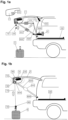
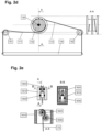
- the main component of the loading and unloading system is a lifting device in the form of an electric motor-driven traction cable system.
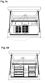
- the traction cable system consists of an electric motor 120, a gearbox 110, a brake 140, a load cable take-up roller 150, load cable guide modules 180, a mounting frame 160, a load cable 170, and a support or crossbar 130 for load support. Heavy items of luggage 5 (payload) can be lifted, held, and lowered using the lifting device.
- the other components of the lifting device are installed in the tailgate 7 of the motor vehicle.
- the length of the crossbar 130 is approximately equal to the width of the tailgate interior (approximately corresponding to the width of the cargo area).
- the baggage 5 (payload) can be suspended at any position on the crossbar 130, allowing a repeated loading process to load multiple heavy pieces of baggage 5 independently and position them on the loading area 220.
- the lifting control electronics including sensors
- load weight, overload, and overheating of the load drive can be detected, and height control of the load handling can be realized.
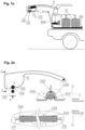
- the crossbar 130 (load carrier) is locked in a recess 190 or depression 1920 of the cover element of the tailgate 7 to avoid mechanical vibrations while driving (when the lifting device is inactive).
- the fastening of the crossbar 130 in the parked position can be realized purely mechanically, for example, by snap-in clips 1910 or spring pushers 1910.
- a sensor 1940 e.g. Hall / contact sensor detects whether the crossbar 130 is in the parked position.
- Figure 2a The crossbar is shown once in the parked position 130 and once in the lowered position 130'.
- the weight of the crossbar 130 must be dimensioned such that sufficient tension is maintained on the load cable 170 even when unloaded, thus ensuring correct load cable routing and winding at all times. In the parked position, the load cables 170 are not under tension, so that the crossbar 130 can be manually pulled out of the trough 190.
- the load cable 170 consists of two cable sections 171, 172 of equal length, which are wound separately in opposite directions on the take-up reel 150, so that when the cable take-up reel 150 rotates in one direction, the two cable ends, each fixed to one end of the crossbar 130, lower or raise simultaneously, depending on the direction of rotation of the cable take-up reel 150.
- the take-up reel 150 thus consists of two reels onto which the cable sections 171, 172 are wound in opposite directions.
- a cable guide module 180 is attached to each cable outlet opening in the tailgate 7.
- the cable guide module 180 ensures the correct deflection of the cable 170 via the rollers 1820, 1830, so that even when the motor vehicle is not in a horizontal position or when balancing the load 5, the load cable 170 does not rub against the tailgate 7 or jump out of the guide 180.
- the rollers 1820, 1830 can be mounted on ball bearings in a holding frame 1810.
- the mechanical load can thus be transferred to the position holders via the anchoring elements 6240.
- the signals 1250 from the overload sensors 1210 are received by the motor module's module processing unit (abbreviated "MPE” 1230) and forwarded to the control unit via the connection bus (such as CAN/LIN) 1260. Furthermore, based on the commands received from the control unit, the module processing unit 1230 controls the electric motor 120 and the electromagnetic brake 140 (signals 1240, 1250).
- MPE motor module's module processing unit
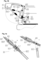
- a not unimportant component of the loading and unloading system can be the implementation of at least one mounting element 60 for mechanically positioning and supporting the lifting device 10 and tailgate 7.
- the task of the positioning elements 620 is to support the lifting device 10 and tailgate 7 and to transfer the mechanical load 5 to the vehicle frame 4. This function is achieved by attaching one end of each positioning element 620 to the mounting frame 160 of the lifting device 10 - referred to as lifting device anchorage 6240 - and the other end to the vehicle frame 4 (trunk frame) - referred to as vehicle frame anchorage 6250. This ensures that the tailgate 7 is held in position during load manipulation and does not move unintentionally.
- Each positioning element 620 of the mounting module consists of a positioning frame 6220 with segments 6221, 6222, and an optional positioning frame actuator/position sensor 6230 including a vehicle wiring harness connection.
- the tailgate 7 is driven in the "opening" direction by a mechanical spring—e.g., a gas spring 630 (i.e., the opening of the tailgate 7 is also enabled “purely passively” by the gas spring 630—like opening a "conventional tailgate”).
- the spring force must be dimensioned to compensate for the increased weight of the tailgate 7 due to the built-in lifting device 10.
- the gas spring 630 ensures that the tailgate 7 is partially opened.
- the motor 6230 then starts to move the tailgate into its final position with the help of the two segments of the positioning frame 6221, 6222.
- Each positioning frame 6220 is implemented by mechanical coding – referred to as the termination element of the positioning frame 6220 – so that "overstepping" the working position is impossible, and reaching the working position can be detected both visually and haptically by the user and electrically by the position sensor 6230.
- the termination element thus fulfills a "poka-yoke” function.
- the positioning elements 620 of the mounting module are recessed into the body 4 when the vehicle is parked (tailgate 7 closed) and are extended from their parked position either manually or electrically for the working position.
- the use of an electric/hydraulic position sensor also enables automated opening/closing of the tailgate 7.
- the optional motor drive (positioning frame actuator 6230), which can be implemented using hydraulic/electrical solutions currently available on the market, must be active in the closing direction of the tailgate 7, whereby manual closing of the tailgate 7 must also be possible (e.g., in the event of a failure of the electrical/electronic system).
- each positioning element 620 is manually locked by the user using a fixing element 610 to secure the working position of the lifting device 10.
- the correct engagement point of the fixing element 610 must be clearly indicated to the user on the positioning element 620, e.g., by colored markings or labeling.
- a pair of sensors 640, 641 – called fixing sensors – can be used in each fixing element 610; see the design according to Figure 4c .
- the position of the fixing element 610 relative to the correct position of the positioning frame 6220 can be electronically detected, and operation of the lifting device 10 is only enabled when the fixing element 610 is in the correct position.
- the sensor 641 it can now be detected whether the fixing element 610 is in the release position (the respective positioning frame 6220 can move into the parking position and the tailgate 7 can be closed).
- the sensor 640 can detect whether the fixing element 610 is in the working position (whether the respective positioning frame 6220 can correctly support the lifting device 10 and thus the tailgate 7 during operation).
- the sensors 640, 641 are installed in the positioning frame 6220. These can be implemented, for example, as Hall sensors that react to the proximity of the fixing element 610.
- the positioning frame 6220 Another possibility for the realization of the positioning frame 6220 is the use of two simple "support rods" (see Figure 4a ), which are lowered in the parked position either in the tailgate 7 or in the trunk floor and then manually moved into the correct position and secured with the fixing element 610.
- the tailgate 7 must be manually or If necessary, it can be opened/closed via an external motor actuator (commercially available solution).
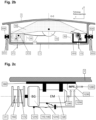
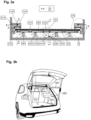
- the loading floor module 20 is designed so that the mobile loading plate 220 is always guided during retraction and extension without the risk of jamming. This prevents the mobile loading plate 220 from becoming wedged, crooked, or "falling out.”
- a guide module 210 is attached to the vehicle body/frame 4 on each side of the mobile loading plate 220 (relative to the vehicle's longitudinal axis - axis "x"). The main function of the two guide modules 210 is to limit the movement of the mobile loading plate 220 exclusively to the x-axis. This is achieved by equipping each guide module with guide rollers 2120 and 2130.
- the limitation of the movement of the mobile loading plate 220 in the z-axis (vertical) is realized by the upper guide rollers 2120, which are in contact with the upper side of the mobile loading plate 220 and thus, in the extended position of the mobile loading plate 220, transfer part of the total weight of the mobile loading plate 220 including the load 4 to the body 4.
- the upper guide rollers 2120 press the mobile loading plate 220 onto the base plate 230 and thus also onto the electric motor drive 240 and onto the support rollers 2310.
- the limitation of the mobile loading plate's movement in the y-axis (horizontal - lateral) is realized by side guide rollers 2130, which are in contact with the lateral side of the mobile loading plate 220.
- two side guide rollers 2130 per guide module 210 are sufficient to suppress the movement of the mobile loading plate 220 in the y-axis direction.
- the movement of the upper guide rollers 2120 is monitored by the control module via rotation sensors 2140 to detect any unexpected blockage of the mobile loading plate 220.
- extension limiters 2220 which are mounted on the mobile loading plate 220, for the mechanical securing of the plate 220 in the "extended” position. This ensures that even if the guide drive 240 fails, the plate 220 does not "fall out of the vehicle.”
- the load distribution elements 2340, 2350 can also have integrated force sensors 280 to make the total weight of the payload 5 measurable.
- the motorized guide drive 2410 which moves the mobile loading plate 220 via a linear gear 2420 (e.g., toothed belt axes), is also attached to the floor frame.
- the guide drive 2410 has sensors 2440, 2430 to detect an accumulation of water in the loading space or an overload of the guide drive 2410.
- the transmission of the power generated by an electric motor 2410 to the mobile loading plate 220 can also be achieved by means of a specially profiled rubber roller 2420 - if the system is designed for lower total loads - or by a traction cable system for higher load capacities.
- a specially profiled rubber roller 2420 - if the system is designed for lower total loads - or by a traction cable system for higher load capacities.
- the vehicle wiring harness connection connects the electric motor drive 240 to the control unit of the loading and unloading system via the vehicle wiring harness.
- the material properties of the mobile loading plate 220 must ensure that when fully extended, the loading plate 220 does not break under full load. This can be achieved, for example, by using composite materials (carbon fiber). Due to the lifting device 10's ability to measure the load weight, the total weight can be roughly calculated even with multiple loads 5, and the user can be warned if the permitted maximum weight is exceeded.
- the top of the mobile loading plate 220 must be designed to be slip-resistant by using appropriate rubber profiles. It is sensible to optionally include edge protection profiles in at least some sections of the loading plate 220, which prevent the payload from slipping sideways off the loading plate and thus making it more difficult to extend the loading plate.
- positioning notches 2210 are milled into the mobile loading plate 220 both at the rear and at the front (relative to the direction of travel).
- the two front (viewed in the direction of travel) positioning notches 2210 are used to position the mobile loading plate 220 by engaging them in positioning wedges 291 of the base frame 290.
- the rear positioning notches 2211 allow the mobile loading plate to be locked using locking bolts 250.
- the contact points between the base frame 290 and the mobile loading plate 220 must have vibration-damping properties (e.g., realized from rubber/silicone profiles).
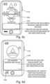
- the type of operating module resulting from the described operating concept can be implemented in various ways, for example as a control panel 310 attached to the vehicle, in particular the tailgate 7 (see Figure 6a ), as remote control 320 (see Figure 6b ) or as Applet 330 for mobile devices such as smartphones, smartwatches (see Figure 6c ), as will be shown later in this chapter.
- the control panel 310 is positioned on the side of the tailgate 7 so that, when the integrated lifting device 10 is in the working position, a child cannot reach the control buttons of the control panel 310. Furthermore, the control electronics are implemented in such a way that the commands can only be activated when the tailgate is opened and moved into the working position and the vehicle is secured while stationary (e.g., handbrake applied, gearshift lever in "P" position). Note: The automatic attachment of the tailgate 7 in the working and closed positions is possible with the operating concept (opening the tailgate via the tailgate switch, vehicle key remote control, button on the inside of the tailgate).
- the control panel 310 includes an on/off button 3110.
- the on/off button 3110 has two positions: in the "pressed” position 3110, the loading and unloading system is "locked, inactive”: all motor actuators are inactive, and available braking elements are active (e.g., the brake 140 of the lifting device 10).
- the on/off button 3110 is in the pressed position, further commands for operating the loading and unloading system (except for the "unlock system” command) are ignored.
- the loading and unloading system In the "pulled-out" position 3110 of the on/off button, the loading and unloading system is "unlocked” and can accept further commands.
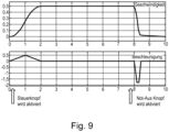
- the On/Off button 3110 is assigned a status indicator 3111, which continuously indicates the availability of the "Emergency Stop” function (e.g., dimmed, continuously lit Emergency Stop symbol and illuminated "Emergency Stop information text" 3111.A), and also indicates the release status of the loading and unloading system, e.g., green when the system is unlocked 3111.B or intense red when the system is locked 3111.C.
- the On/Off button 3110 By pressing the On/Off button 3110 while the crossbar 130 or the loading plate 220 is moving, the respective drive is brought to a rapid standstill by activating the brake.
- the emergency stop braking profile is defined in Figure 9 presented informatively.
- the control panel 310 includes two control buttons for raising/lowering load 5 by the lifting device 10.
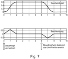
- the lifting device 10 is controlled via the "UP" buttons 3120 and "DOWN” 3130. If neither button is pressed, the lifting device 10 holds the crossbar 130 and load 5 in the currently reached position (using the lifting device brake 140). As long as the "UP” button 3120 is pressed, the lifting device 10 raises the crossbar 130 and any attached load 5. Upon reaching a predefined “Limit-Top Position,” the crossbar 130 remains in this position even when the "UP" button 3120 is pressed again.
- the acceleration and speed profile in the vertical direction are shown in Figure 8 presented informatively.
- the lifting device 10 can detect when the crossbar 130 is not under load (e.g., by measuring the motor load current of the motor 140). After attaching the load 5 to the crossbar 130 (e.g., using lifting straps), the lifting device 10 must first lift the crossbar 130 relatively quickly, as long as the load 5 is not "hanging" and the straps are not tensioned. In order to properly tension the lifting straps (and thus ensure the correct hanging position of the load 5), the lifting device 10 must stop the movement of the crossbar 130 before the load 5 is completely suspended from the crossbar 130, thus allowing readjustment of the lifting straps.
- the acceleration and speed profile for this application is shown in Fig. 8 presented informatively.
- the control panel 310 includes two control buttons for moving the load 5 into and out of the trunk through the loading floor module 20.
- the mobile loading plate 320 is controlled via the "IN” buttons 3140 and "OUT” buttons 3150. If neither of the buttons 3140 and 3150 is pressed, the drive 240 of the mobile loading plate 220 (via the drive brake) holds the mobile loading plate 220 and load 5 in the currently reached position.
- the mobile loading plate 220, along with load 5 is moved out of the loading space 130.
- the mobile loading plate remains in this position even if the "Out” button 3150 is pressed again.
- the mobile loading plate 220, along with load 5 is moved into the loading space 130.
- the mobile loading plate 220 remains in this position even if the "IN” button 3140 is pressed again.
- control profiles of the forces applied to the crossbar 130 by the drive 120 of the lifting device 10 and to the mobile loading plate 220 by the drive 2320 of the mobile loading plate 220 must be designed so that no jerky movement of the load is caused.
- Such control profiles are known, for example, from robotics.
- the control elements are visually marked in such a way that the various positions of the tailgate 7 make it difficult to mix up the control functions.
- the control elements are illuminated when the system is active, to enable operation even in the dark.
- the control panel 310 includes a light indicator 3170 for signaling the current system status, so that the user has a quick overview.
- the light indicator has three colors, the meaning of which has already been defined above.
- the control panel 310 includes a buzzer 3180 for the audible warning when the lifting device 10 or the mobile loading plate 220 are moving (e.g., intermittent beeping). Furthermore, the buzzer can be active when the tailgate 7 opens or closes.
- the control panel 310 includes a text display 3160.
- general information (error status, maintenance instructions) can be displayed.
- the text display is optional, as the information can also be displayed on other information display devices (e.g., on-board computer).
- a further variation of the operating concept, as shown above, can be achieved by an optional remote control 320 ( Fig. 6b ) be realized. While controlling the system via the control panel 310 requires the user to be in close proximity to the control panel 310, control can be exercised more flexibly via the remote control 320 (e.g., to manually orient bulky loads 5 if necessary).
- the remote control 320 can be part of the vehicle key or a separate module (e.g., a key fob).
- the remote control 320 only has the control buttons "UP" 3220, "DOWN” 3230, "IN” 3240, and "OUT" 3250.
- control panel 310 On/Off button 3110; light indicator 3170; buzzer 3180; text display 3160
- the arrangement of the control buttons 3220, 3230, 3240, 3250 on the 320 remote control is designed so that the functionality of each button can be recognized haptically. Examples are described in the implementation section of this document.
- the control buttons can send commands to the system controller when the vehicle is unlocked and the tailgate 7 is in the working position; otherwise, these control buttons are inoperative.
- the tailgate 7 is in the working position when the crossbar 130 is not in its parked position and the support module of the lifting device 10 is fixed in accordance with the operating concept.
- the control buttons 3120, 3130, 3140, 3150 can also be used for load movement. on the control panel. Even when using a remote control 320 or a control application (p. Figure 6c ), the control panel 310 on the vehicle must include the following elements: On/Off button 3110, light indicator 3170, and buzzer 3180.
- the On/Off button can be used to "park" the lifting device 10. If the remote control 320 is integrated into the vehicle key, the vehicle lock button (of the remote control) can be used as an emergency stop button.
- a further development of the operating concept is an optional "control app” 330 (according to Figure 6c ), integrated into a mobile device such as a cell phone, tablet, smartwatch, and the like.
- the mobile device can communicate with the vehicle management system (e.g., vehicle gateway or body controller control unit) via Bluetooth or WiFi.
- the control app 330 communicates with the body controller, which forwards the commands and status information to the control unit of the loading and unloading system (body controller as a relay function). If the vehicle management control unit - e.g., body controller - does not support wireless communication with other devices, communication with the control app can be realized directly from the control unit of the loading and unloading system.
- radio control via remote control 320 or via control app 330
- the control app 330 is implemented in such a way that the functions of the loading and unloading system can be started from a main window 3310.
- the main window consists of the graphical representation of the control buttons 3120, 3130, 3140, and 3150 for load movement, a selection-confirmation button 3320, and the information display 3160.
- the introduction of the confirmation button ensures that an unintentional activation of the loading and unloading system's functions cannot occur. Only the sequence "control element / confirmation element" may lead to function release.
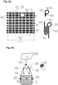
- load carriers 50 can be designed either as a net (load net) or as a box (load box).
- Cargo net The cargo net can be the full width of the cargo area ("full-width net”) or, for example, only half the width of the cargo area (“half-width net”). This allows for a variety of applications. Larger bags, such as those sold in garden centers, are handled with a full-width net, while smaller bags (e.g., cement bags) or beverage crates are handled with a half-width net.
- the load net consists of a flat net 510 provided with perpendicularly arranged reinforcement straps (load-bearing reinforcement straps 520) and stabilizing reinforcement straps 530.
- the load-bearing reinforcement straps 521 serve to suspend the load net from the crossbar 130 of the lifting device 10.
- the stabilizing reinforcement straps 530 serve only to ensure the positional stability of the load-bearing reinforcement straps 520.
- the load net is suspended from the lifting crossbar 130 using straps 580 and anchors 590 (carabiners) attached to the hanging loops 540.
- the load-bearing and stabilizing reinforcement straps 520, 530 are sewn or riveted together at their intersection points 560.
- Hanging loops Hanging the load net (including payload 5) from the crossbar 130 of the lifting device 10 is made possible by implementing hanging loops 540 at the ends of the load-bearing reinforcement straps 520. Furthermore, at certain points where the load-bearing reinforcement straps 520 and the stabilizing reinforcement straps 530 intersect, intermediate hanging loops 550 are attached to enable optimal suspension of the payload 5.
- the stabilizing reinforcement straps 530 also have loops 533 at their ends to allow the load net to be tied laterally using adjustable securing straps 570.
- Load box instead of the load net, which is not dimensionally stable and is therefore more suitable for boxed goods/bagged goods, a folding box 53 specially designed for this purpose can be used (see Figure 5d ).
- the folding box 53 has hanging loops or eyelets 531 on its long and/or transverse sides for hanging from the crossbar 130 using hanging straps and snap hooks in a longitudinal or transverse position.
- the load box should be stackable to support several such fully loaded boxes.
- LF_OpMdCtrl Control Operating Modes
- LF_UsrMdlCtrl Control Operating Modules
- LF_Control Operating Modes LF_OpMdCtrl
- the control function of the lifting device 10 is implemented in such a way that the function "Control lifting device” LF_LftMdlCtrl sends commands to the function block "Control actuators” LF_ActCtrl and receives status information from the function block "Control actuators” LF_ActCtrl.
- the control function of the loading floor module 20 is implemented in such a way that the function "Control loading floor module” LF_LdrCrrCtrl sends commands to the function block "Control actuators” LF_ActCtrl and receives status information from the function block "Control actuators” LF_ActCtrl.
- the control function of the lifting device support module 60 is implemented in such a way that the function "Control support module” LF_SprtMdlCtrl commands on the Function block "Control actuators” LF_ActCtrl sends, and receives status information from the function block "Control actuators” LF_ActCtrl.
- the "Actuator Control” function LF_ActCtrl converts logical commands received from the various control functions (LF_LftMdlCtrl, LF_LdrCrrCtrl, LF_SprtMdlCtrl) into physical control signals required by the various actuators to perform the customer functions.
- the "Actuator Control” function LF_ActCtrl is implemented in such a way that a logical command corresponding to a movement profile (e.g., "Move crossbar 130 upwards without load") is assigned a calibrated profile of control signals specifically assigned to an actuator (e.g., BLDC motor / brushless DC electric motor).
- the "Control Actuators" function LF_ActCtrl is implemented in such a way that information reflecting the physical status of an actuator is communicated to the higher-level control module (LF_LftMdlCtrl, LF_LdrCrrCztl, LF_SprtMdlCtrl).
- This allows the higher-level control module to assign the physical actuator status to a logical functional status (e.g., "Lifting device overloaded") and communicate this status to the "Control Operating Modes" function module LF_OpMdCtrl.
- LF_IndLdhMon serves as an additional monitoring mechanism to detect system errors and initiate an emergency shutdown. For this purpose, information is collected from the sensors. and evaluated, together with status information from the control modules (LF_LftMdlCtrl, LF_LdrCrrCztl, LF_SprtMdlCtrl).
- LF_VehComm ensures the necessary flow of information between the control of the loading and unloading system and the vehicle management.
- Phase 1 "Reaching the working position” the tailgate 7 is opened, e.g., through the cooperation of gas springs 630 and electromotive actuators 6230.
- the position holders 610 are moved into their working position, which is indicated by the reference number 610'.
- the load carrier rod 130 is manually moved from the parking position to the standby position (reference number 130') in order to be able to pick up the stored luggage 5 in the subsequent steps.
- Figure 1b shows phase 2, "Load Lifting.”
- a piece of luggage 5 which is held to the crossbar 130 by a fastening element 580, is lifted to the highest position by the lifting device 10 using the two load cables 170.
- the control unit can determine the path of the load cables 170, the control unit can also calculate how high the load 5 must be lifted in order to then lower it onto the loading floor 220.
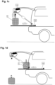
- phase 3 "Loading" shown in Figure 1c , the mobile loading plate 220 is extended while the load 5 is raised sufficiently to avoid a collision with the mobile loading plate 220. After the loading plate 220 is in the load-picking position, the load 5 is lowered onto the loading plate 220.
- phase 4 "Stowing", shown in Figure 1d , the mobile loading plate 220 is retracted into the trunk. Due to the adjustable positioning of the mobile loading plate 220, phases 2 to 4 can be repeated several times in order to load several load items 5.
- the loading plate 220 is locked, the load carrier rod 130 is attached to the trunk lid (parking position) and the position holder 610 is brought into the parking position.
Landscapes
- Engineering & Computer Science (AREA)
- Mechanical Engineering (AREA)
- Transportation (AREA)
- Power-Operated Mechanisms For Wings (AREA)
- Handcart (AREA)
- Warehouses Or Storage Devices (AREA)
- Electric Cable Arrangement Between Relatively Moving Parts (AREA)
- Loading Or Unloading Of Vehicles (AREA)
Claims (13)
- Véhicule automobile avec au moins un dispositif de levage (10) intégré dans le hayon arrière (7) comprenant un système de câble de traction à moteur électrique constituéd'au moins un câble de charge (170),d'au moins une bobine de réception (150) entraînée par moteur électrique pour enrouler et dérouler le câble de charge (170) etd'un guide-câble (180), au moyen duquel au moins deux faisceaux de câbles parallèles sont guidés hors du hayon arrière (7) en direction du sol, les faisceaux de câbles parallèles étant reliés aux extrémités au moyen d'une barre de support (130) en tant que moyen de réception de charge,caractérisé en ce qu'au moins un cadre de montage (160) pour le dispositif de levage (10) est prévu dans le hayon arrière (7), sur lequel sont logés l'au moins un rouleau de réception (150), y compris l'entraînement par moteur électrique (120) et éventuellement le guide-câble (180), et au moins un, de préférence deux éléments de positionnement (620) sont prévus, qui sont logés à l'extrémité sur le cadre de montage (160) et à leur autre extrémité sont logés sur le cadre de véhicule (4) du véhicule automobile, de telle sorte qu'une transmission de force directe du cadre de montage (160) dans la carrosserie du véhicule a lieu.
- Véhicule automobile selon la revendication 1, caractérisé en ce que le cadre de montage (160) s'étend, en position installée à l'intérieur du hayon arrière (7), sur presque toute la largeur du hayon arrière (7).
- Véhicule automobile selon l'une quelconque des revendications précédentes, caractérisé en ce que le guide-câble (180) présente un agencement de rouleaux (1820, 1830) par faisceau de câbles, afin de guider le câble de charge (170) hors du hayon arrière (7) à l'emplacement de sortie souhaité, les agencements de rouleaux (1820, 1830) étant de préférence logés sur les extrémités libres du cadre de montage (160), tandis que l'au moins un rouleau de réception (150) est logé sur le cadre de montage (160) au centre entre les agencements de rouleaux (1820, 1830).
- Véhicule automobile selon l'une quelconque des revendications précédentes, caractérisé en ce que le câble de charge (170) est constitué de deux câbles séparés ou sections de câble séparées (171, 172) de même longueur et le rouleau de réception (150) présente deux bobines juxtaposées sur l'axe de rouleau pour enrouler et dérouler les câbles ou sections de câble.
- Véhicule automobile selon l'une quelconque des revendications précédentes, caractérisé en ce que l'entraînement par moteur électrique de la bobine de réception (150) comprend un moteur électrique (120) avec broche, engrenage (110) et frein (140), notamment avec fonction de freinage d'urgence et de libération manuelle en cas de freinage d'urgence préalablement déclenché, et/ou est équipé d'un système de détection (1210) pour mesurer le poids de charge reçu et/ou la course de levage et/ou la température de fonctionnement.
- Véhicule automobile selon l'une quelconque des revendications précédentes, caractérisé en ce que l'au moins un élément de positionnement (620) comprend une cinématique de levier (6220) qui est réglable avec un mouvement d'ouverture/fermeture du hayon arrière (7) du véhicule, de préférence au moins un entraînement (6230), notamment un entraînement électrique ou électrohydraulique, étant prévu pour actionner la cinématique de levier de l'élément de positionnement (620).
- Véhicule automobile selon la revendication 6, caractérisé en ce que l'au moins un élément de positionnement (620) comprend un moyen de fixation (610) pour bloquer la cinématique de levier (6220), de préférence au moins un système de détection (640, 641) étant prévu pour détecter l'état du moyen de fixation (610) ou de la cinématique de levier (6220).
- Véhicule automobile selon l'une quelconque des revendications 6 à 8 précédentes, caractérisé par une unité de commande avec au moins un module de contrôle, qui sont configurés pour commander une libération de l'entraînement par moteur électrique (120) du rouleau de réception (150) selon un concept de contrôle et/ou en fonction de l'état des éléments de positionnement (620) ou de la cinématique de levier (6220) et/ou du véhicule automobile.
- Véhicule automobile selon l'une quelconque des revendications précédentes, caractérisé en ce que le véhicule automobile comprend au moins un module de plancher de chargement rétractable et extensible.
- Véhicule automobile selon la revendication 9, caractérisé en ce que le module de plancher de chargement comprend :un châssis de plancher, sur le côté inférieur duquel sont agencés un ou plusieurs éléments d'appui pour s'appuyer sur le plancher de l'espace de chargement du véhicule automobile et sur le côté supérieur duquel sont installés un ou plusieurs rouleaux porteurs,un plateau de chargement qui est logé sur le châssis de plancher de manière à pouvoir se déplacer dans la direction longitudinale par rapport à celui-ci à l'aide des rouleaux porteurs, etau moins deux modules de guidage avec des emplacements de liaison pour la fixation sur les parois latérales de l'espace de chargement du véhicule, les modules de guidage présentant chacun au moins un rouleau de guidage roulant sur la surface du plateau de chargement pour guider le plateau de chargement le long de ses côtés longitudinaux.
- Véhicule automobile selon la revendication 10, caractérisé en ce que les modules de guidage présentent chacun au moins un rouleau de guidage latéral qui roule le long des bords longitudinaux du plateau de chargement.
- Véhicule automobile selon l'une quelconque des revendications 10 ou 11 , caractérisé en ce qu'il est prévu un cadre s'étendant au moins par sections autour du plateau de chargement et relié au châssis de plancher, qui comprend de préférence un ou plusieurs éléments de verrouillage pour immobiliser temporairement le plateau de chargement par rapport au châssis de plancher.
- Véhicule automobile selon l'une quelconque des revendications 10 à 12, caractérisé en ce qu'il est prévu au moins un entraînement pour le déplacement motorisé du plateau de chargement par rapport au châssis de plancher, notamment pour l'entraînement d'au moins un rouleau porteur, et/ou au moins un système de détection de charge intégré dans le châssis de plancher pour détecter le poids de charge du chargement du plateau de chargement.
Applications Claiming Priority (3)
| Application Number | Priority Date | Filing Date | Title |
|---|---|---|---|
| DE102020005485 | 2020-09-07 | ||
| DE102021101477.8A DE102021101477B4 (de) | 2020-09-07 | 2021-01-25 | Hebevorrichtung zur Integration in einer Heckklappe eines Kraftfahrzeugs, Ladebodenmodul und System zum Be- und Entladen eines Kraftfahrzeuges |
| PCT/EP2021/071475 WO2022048834A1 (fr) | 2020-09-07 | 2021-07-30 | Dispositif de levage destiné à être intégré dans un hayon d'un véhicule automobile, module de base de chargement et système de chargement et de déchargement d'un véhicule automobile |
Publications (3)
| Publication Number | Publication Date |
|---|---|
| EP4171998A1 EP4171998A1 (fr) | 2023-05-03 |
| EP4171998B1 true EP4171998B1 (fr) | 2025-05-21 |
| EP4171998C0 EP4171998C0 (fr) | 2025-05-21 |
Family
ID=80266782
Family Applications (1)
| Application Number | Title | Priority Date | Filing Date |
|---|---|---|---|
| EP21755725.5A Active EP4171998B1 (fr) | 2020-09-07 | 2021-07-30 | Véhicule à moteur avec au moins un dispositif de levage intégré dans le hayon arrière |
Country Status (6)
| Country | Link |
|---|---|
| US (1) | US12528414B2 (fr) |
| EP (1) | EP4171998B1 (fr) |
| CN (1) | CN116018290A (fr) |
| CA (1) | CA3193301A1 (fr) |
| DE (1) | DE102021101477B4 (fr) |
| WO (1) | WO2022048834A1 (fr) |
Families Citing this family (5)
| Publication number | Priority date | Publication date | Assignee | Title |
|---|---|---|---|---|
| IT202300002091A1 (it) * | 2023-02-08 | 2024-08-08 | Fiat Ricerche | "vano bagagli di autoveicolo provvisto di un'apparecchiatura di sollevamento per sollevare oggetti da caricare nel vano bagagli" |
| CN117088279A (zh) * | 2023-08-23 | 2023-11-21 | 泰州三福船舶工程有限公司 | 一种舱口盖的支撑式便携式吊具结构 |
| ES3032842A1 (es) * | 2024-01-24 | 2025-07-28 | Univ Valladolid | Sistema de carga de equipaje en vehiculo sin esfuerzo |
| FR3159357A1 (fr) | 2024-02-16 | 2025-08-22 | Stellantis Auto Sas | Panier de rangement sous le capot d’un coffre avant de vehicule automobile |
| CN120117185B (zh) * | 2025-05-14 | 2025-09-05 | 杭州瑞利超声科技有限公司 | 一种适用于机载吊放声呐的拆装装置及其工作方法 |
Family Cites Families (32)
| Publication number | Priority date | Publication date | Assignee | Title |
|---|---|---|---|---|
| US4002321A (en) * | 1975-07-07 | 1977-01-11 | Cecil A. Pelts | Tiltable drums for winding hoist lines |
| US5054578A (en) | 1987-02-24 | 1991-10-08 | C. M. Smillie & Company | Power-operated lift and presenting mechanism |
| US4969793A (en) | 1988-02-16 | 1990-11-13 | Pawl E Timothy | Power trunk lift |
| CA1295580C (fr) * | 1989-06-14 | 1992-02-11 | Bernard Bergeron | Appareil de manutention de marchandises |
| US5209435A (en) * | 1989-10-24 | 1993-05-11 | Futrex, Inc. | Passsenger car with emergency exit |
| US5454684A (en) * | 1994-05-31 | 1995-10-03 | Berens; Robin H. | Rollout dumping box for utility vehicle |
| US5456511A (en) | 1994-08-03 | 1995-10-10 | Webber; Albert F. | Truck bed extender |
| US6065792A (en) | 1997-06-05 | 2000-05-23 | Sciullo; John E. | Slide-a-bed system for a truck |
| DE19731324A1 (de) | 1997-07-22 | 1999-03-11 | Bayerische Motoren Werke Ag | Ausziehbarer Ladeboden für ein Fahrzeug |
| DE19815466A1 (de) | 1998-04-07 | 1999-10-14 | Marcel Franz | Be- und Entladegerät |
| DE10006617C1 (de) | 2000-02-15 | 2001-07-12 | Daimler Chrysler Ag | Ausfahrbarer Ladeboden für ein Kraftfahrzeug |
| DE10012767B4 (de) | 2000-03-16 | 2007-05-24 | Webasto Ag | Ladesystem für den Laderaum eines Fahrzeugs |
| AT409620B (de) | 2000-04-11 | 2002-09-25 | Intier Automotive Eybl Gmbh | Ladeboden |
| DE10054572A1 (de) | 2000-11-03 | 2002-05-08 | Opel Adam Ag | Ladesystem für den Laderaum eines Fahrzeugs |
| US20030141733A1 (en) | 2002-01-31 | 2003-07-31 | Burg Donald E. | Vehicle with extendable cargo bed |
| DE10213307A1 (de) | 2002-03-25 | 2003-10-23 | Sai Automotive Sal Gmbh | Ladeboden für ein Fahrzeug und Beladevorrichtung |
| DE10312466B4 (de) | 2003-03-20 | 2006-06-14 | Webasto Ag | Ladesystem für einen Laderaum eines Kraftfahrzeuges |
| US7334776B2 (en) | 2004-07-08 | 2008-02-26 | Homayoon Kazerooni | Apparatus and method for vehicle on-board cargo handling system |
| DE102004051622B4 (de) | 2004-10-22 | 2013-08-22 | Sortimo Speedwave Gmbh | Ladeboden für den Gepäckraum eines Fahrzeugs |
| US7543873B1 (en) * | 2006-12-08 | 2009-06-09 | Joseph Warren Thornsberry | Roll-out drawer system for a vehicle |
| DE102008044282A1 (de) | 2008-12-02 | 2010-06-10 | Fredy Witter | Ladevorrichtung für einen Gepäckraum eines Pkw |
| DE202009014248U1 (de) | 2009-10-22 | 2010-03-04 | Schmid, Otto E., Dipl.-Ing. (FH) | Aufbrech- und Transportvorrichtung für Wild |
| US8398358B2 (en) | 2010-04-14 | 2013-03-19 | Jerry L'Ecuyer | Automobile luggage compartment storage device |
| US9114876B1 (en) * | 2013-03-15 | 2015-08-25 | Air Rescue Systems Corporation | Quick rope assisted deployment and extraction apparatus |
| FR3010967B1 (fr) | 2013-09-23 | 2015-10-23 | Peugeot Citroen Automobiles Sa | Dispositif de coulissement pour un faux plancher d'un vehicule automobile |
| US10919428B2 (en) | 2015-08-07 | 2021-02-16 | Ford Global Technologies, Llc | Powered sliding platform assembly |
| DE202015105898U1 (de) | 2015-11-05 | 2017-02-07 | Smp Deutschland Gmbh | Hebevorrichtung zum Be- und Entladen eines Kofferraums eines Fahrzeugs |
| US10532774B2 (en) | 2016-08-09 | 2020-01-14 | Ford Global Technologies, Llc | Vehicle liftgate with dual stowable hoists |
| JP6610593B2 (ja) | 2017-03-24 | 2019-11-27 | トヨタ自動車株式会社 | バックドア構造 |
| US10500933B2 (en) | 2017-05-10 | 2019-12-10 | Ford Global Technologies, Llc | Apparatus and method for loading and deploying cargo from a motor vehicle |
| US11608002B2 (en) | 2018-08-08 | 2023-03-21 | Uatc, Llc | Transportation receptacle for vehicles |
| WO2020060473A1 (fr) | 2018-09-18 | 2020-03-26 | Kyttinge Investment Ab | Système et procédé de chargement et de déchargement d'un article dans et hors d'un coffre d'une voiture |
-
2021
- 2021-01-25 DE DE102021101477.8A patent/DE102021101477B4/de active Active
- 2021-07-30 CN CN202180054826.4A patent/CN116018290A/zh active Pending
- 2021-07-30 WO PCT/EP2021/071475 patent/WO2022048834A1/fr not_active Ceased
- 2021-07-30 US US18/043,292 patent/US12528414B2/en active Active
- 2021-07-30 CA CA3193301A patent/CA3193301A1/fr active Pending
- 2021-07-30 EP EP21755725.5A patent/EP4171998B1/fr active Active
Also Published As
| Publication number | Publication date |
|---|---|
| US20240025346A1 (en) | 2024-01-25 |
| WO2022048834A1 (fr) | 2022-03-10 |
| US12528414B2 (en) | 2026-01-20 |
| EP4171998A1 (fr) | 2023-05-03 |
| DE102021101477A1 (de) | 2022-03-10 |
| CN116018290A (zh) | 2023-04-25 |
| CA3193301A1 (fr) | 2022-03-10 |
| DE102021101477B4 (de) | 2022-07-14 |
| EP4171998C0 (fr) | 2025-05-21 |
Similar Documents
| Publication | Publication Date | Title |
|---|---|---|
| EP4171998B1 (fr) | Véhicule à moteur avec au moins un dispositif de levage intégré dans le hayon arrière | |
| DE602004009053T2 (de) | Lenkbare /einziehbare frachtkraftantriebseinheit | |
| EP1415908B1 (fr) | Système de chargement de marchandises | |
| EP1305249B1 (fr) | Cabine d'ascenseur disposant d'une machine d'entrainement de poulie motrice integree | |
| DE102014118011B4 (de) | Fahrradträgersystem für ein Fahrzeug | |
| EP3071165B1 (fr) | Commande de roulettes montées sur un élément mobile | |
| EP2195182A1 (fr) | Dispositif de pivotement pour une portière de véhicule | |
| DE202019105694U1 (de) | Fahrzeugträgerbaugruppe | |
| EP3459851A1 (fr) | Combinaison de chariot transporteur à entraînement électrique pour une cabine d'avion | |
| DE102011118550A1 (de) | Gepäckablagefach für ein Flugzeug und Flugzeug mit dem Gepäckablagefach | |
| CN105672787A (zh) | 用于车辆的门把手组件 | |
| WO2017036910A2 (fr) | Dipsositif doté d'un élément de recouvrement de fond pour compartiment de chargement | |
| EP3353108B1 (fr) | Dispositif de surveillance d'ascenseur | |
| WO2016094923A2 (fr) | Système de stockage à compensation d'énergie améliorée entre transtockeurs | |
| KR102250313B1 (ko) | 전동조향 기능을 가지는 전동손수레 | |
| EP3212560A1 (fr) | Appareil élévateur à portique pour conteneurs iso | |
| DE69821248T2 (de) | Steuerungseinrichtung für einen aufzug | |
| DE102011078803B4 (de) | System und Verfahren zum automatisierten Hinaufziehen einer Fahrtrage in einen Rettungswagen | |
| DE102020116187A1 (de) | Verfahren zum Laden von Komponenten in ein Fahrzeug | |
| EP3006389B1 (fr) | Transstockeur et procede de fonctionnement d'un transstockeur | |
| DE102018128099A1 (de) | Elektro-transportwagen | |
| DE10114571A1 (de) | Batterie-elektrisch betriebenes Flurförderzeug, insbesondere Gegengewichtsstapler | |
| DE202012101614U1 (de) | PKW-Ladevorrichtung zum Ein- und Ausladen eines Kleinfahrzeugs sowie Kleinfahrzeug | |
| DE102017220199B3 (de) | Ladevorrichtung, Kraftfahrzeug und Mobilitätssystem | |
| EP1882668B1 (fr) | Ascenseur avec moteur placé dans le contre-poids |
Legal Events
| Date | Code | Title | Description |
|---|---|---|---|
| STAA | Information on the status of an ep patent application or granted ep patent |
Free format text: STATUS: UNKNOWN |
|
| STAA | Information on the status of an ep patent application or granted ep patent |
Free format text: STATUS: THE INTERNATIONAL PUBLICATION HAS BEEN MADE |
|
| PUAI | Public reference made under article 153(3) epc to a published international application that has entered the european phase |
Free format text: ORIGINAL CODE: 0009012 |
|
| STAA | Information on the status of an ep patent application or granted ep patent |
Free format text: STATUS: REQUEST FOR EXAMINATION WAS MADE |
|
| 17P | Request for examination filed |
Effective date: 20230127 |
|
| AK | Designated contracting states |
Kind code of ref document: A1 Designated state(s): AL AT BE BG CH CY CZ DE DK EE ES FI FR GB GR HR HU IE IS IT LI LT LU LV MC MK MT NL NO PL PT RO RS SE SI SK SM TR |
|
| DAV | Request for validation of the european patent (deleted) | ||
| DAX | Request for extension of the european patent (deleted) | ||
| GRAP | Despatch of communication of intention to grant a patent |
Free format text: ORIGINAL CODE: EPIDOSNIGR1 |
|
| STAA | Information on the status of an ep patent application or granted ep patent |
Free format text: STATUS: GRANT OF PATENT IS INTENDED |
|
| INTG | Intention to grant announced |
Effective date: 20250117 |
|
| GRAS | Grant fee paid |
Free format text: ORIGINAL CODE: EPIDOSNIGR3 |
|
| GRAA | (expected) grant |
Free format text: ORIGINAL CODE: 0009210 |
|
| STAA | Information on the status of an ep patent application or granted ep patent |
Free format text: STATUS: THE PATENT HAS BEEN GRANTED |
|
| AK | Designated contracting states |
Kind code of ref document: B1 Designated state(s): AL AT BE BG CH CY CZ DE DK EE ES FI FR GB GR HR HU IE IS IT LI LT LU LV MC MK MT NL NO PL PT RO RS SE SI SK SM TR |
|
| REG | Reference to a national code |
Ref country code: GB Ref legal event code: FG4D Free format text: NOT ENGLISH |
|
| REG | Reference to a national code |
Ref country code: CH Ref legal event code: EP |
|
| REG | Reference to a national code |
Ref country code: DE Ref legal event code: R096 Ref document number: 502021007550 Country of ref document: DE |
|
| REG | Reference to a national code |
Ref country code: IE Ref legal event code: FG4D Free format text: LANGUAGE OF EP DOCUMENT: GERMAN |
|
| U01 | Request for unitary effect filed |
Effective date: 20250530 |
|
| U07 | Unitary effect registered |
Designated state(s): AT BE BG DE DK EE FI FR IT LT LU LV MT NL PT RO SE SI Effective date: 20250605 |
|
| U79 | Statement concerning licences of right filed [unitary effect] |
Effective date: 20250605 |
|
| U20 | Renewal fee for the european patent with unitary effect paid |
Year of fee payment: 5 Effective date: 20250723 |
|
| PG25 | Lapsed in a contracting state [announced via postgrant information from national office to epo] |
Ref country code: ES Free format text: LAPSE BECAUSE OF FAILURE TO SUBMIT A TRANSLATION OF THE DESCRIPTION OR TO PAY THE FEE WITHIN THE PRESCRIBED TIME-LIMIT Effective date: 20250521 |
|
| PG25 | Lapsed in a contracting state [announced via postgrant information from national office to epo] |
Ref country code: NO Free format text: LAPSE BECAUSE OF FAILURE TO SUBMIT A TRANSLATION OF THE DESCRIPTION OR TO PAY THE FEE WITHIN THE PRESCRIBED TIME-LIMIT Effective date: 20250821 Ref country code: GR Free format text: LAPSE BECAUSE OF FAILURE TO SUBMIT A TRANSLATION OF THE DESCRIPTION OR TO PAY THE FEE WITHIN THE PRESCRIBED TIME-LIMIT Effective date: 20250822 |
|
| PG25 | Lapsed in a contracting state [announced via postgrant information from national office to epo] |
Ref country code: PL Free format text: LAPSE BECAUSE OF FAILURE TO SUBMIT A TRANSLATION OF THE DESCRIPTION OR TO PAY THE FEE WITHIN THE PRESCRIBED TIME-LIMIT Effective date: 20250521 |
|
| PG25 | Lapsed in a contracting state [announced via postgrant information from national office to epo] |
Ref country code: HR Free format text: LAPSE BECAUSE OF FAILURE TO SUBMIT A TRANSLATION OF THE DESCRIPTION OR TO PAY THE FEE WITHIN THE PRESCRIBED TIME-LIMIT Effective date: 20250521 |
|
| PG25 | Lapsed in a contracting state [announced via postgrant information from national office to epo] |
Ref country code: RS Free format text: LAPSE BECAUSE OF FAILURE TO SUBMIT A TRANSLATION OF THE DESCRIPTION OR TO PAY THE FEE WITHIN THE PRESCRIBED TIME-LIMIT Effective date: 20250821 |
|
| PG25 | Lapsed in a contracting state [announced via postgrant information from national office to epo] |
Ref country code: IS Free format text: LAPSE BECAUSE OF FAILURE TO SUBMIT A TRANSLATION OF THE DESCRIPTION OR TO PAY THE FEE WITHIN THE PRESCRIBED TIME-LIMIT Effective date: 20250921 |
|
| U1N | Appointed representative for the unitary patent procedure changed after the registration of the unitary effect |
Representative=s name: LORENZ SEIDLER GOSSEL PART. MBB; DE |
|
| PGFP | Annual fee paid to national office [announced via postgrant information from national office to epo] |
Ref country code: GB Payment date: 20251111 Year of fee payment: 5 |
|
| PG25 | Lapsed in a contracting state [announced via postgrant information from national office to epo] |
Ref country code: SM Free format text: LAPSE BECAUSE OF FAILURE TO SUBMIT A TRANSLATION OF THE DESCRIPTION OR TO PAY THE FEE WITHIN THE PRESCRIBED TIME-LIMIT Effective date: 20250521 |
|
| PG25 | Lapsed in a contracting state [announced via postgrant information from national office to epo] |
Ref country code: CZ Free format text: LAPSE BECAUSE OF FAILURE TO SUBMIT A TRANSLATION OF THE DESCRIPTION OR TO PAY THE FEE WITHIN THE PRESCRIBED TIME-LIMIT Effective date: 20250521 |
|
| PG25 | Lapsed in a contracting state [announced via postgrant information from national office to epo] |
Ref country code: SK Free format text: LAPSE BECAUSE OF FAILURE TO SUBMIT A TRANSLATION OF THE DESCRIPTION OR TO PAY THE FEE WITHIN THE PRESCRIBED TIME-LIMIT Effective date: 20250521 |
|
| REG | Reference to a national code |
Ref country code: CH Ref legal event code: H13 Free format text: ST27 STATUS EVENT CODE: U-0-0-H10-H13 (AS PROVIDED BY THE NATIONAL OFFICE) Effective date: 20260224 |
|
| PLBE | No opposition filed within time limit |
Free format text: ORIGINAL CODE: 0009261 |
|
| STAA | Information on the status of an ep patent application or granted ep patent |
Free format text: STATUS: NO OPPOSITION FILED WITHIN TIME LIMIT |
|
| REG | Reference to a national code |
Ref country code: CH Ref legal event code: L10 Free format text: ST27 STATUS EVENT CODE: U-0-0-L10-L00 (AS PROVIDED BY THE NATIONAL OFFICE) Effective date: 20260402 |
|
| PG25 | Lapsed in a contracting state [announced via postgrant information from national office to epo] |
Ref country code: CH Free format text: LAPSE BECAUSE OF NON-PAYMENT OF DUE FEES Effective date: 20250731 |
|
| REG | Reference to a national code |
Ref country code: CH Ref legal event code: Y10 Free format text: ST27 STATUS EVENT CODE: U-0-0-Y10-Y00 (AS PROVIDED BY THE NATIONAL OFFICE) Effective date: 20260423 |
|
| 26N | No opposition filed |
Effective date: 20260224 |