EP4172436B1 - Agencement de verrouillage - Google Patents
Agencement de verrouillage Download PDFInfo
- Publication number
- EP4172436B1 EP4172436B1 EP21737828.0A EP21737828A EP4172436B1 EP 4172436 B1 EP4172436 B1 EP 4172436B1 EP 21737828 A EP21737828 A EP 21737828A EP 4172436 B1 EP4172436 B1 EP 4172436B1
- Authority
- EP
- European Patent Office
- Prior art keywords
- locking
- locking bolt
- blocking
- door
- arm
- Prior art date
- Legal status (The legal status is an assumption and is not a legal conclusion. Google has not performed a legal analysis and makes no representation as to the accuracy of the status listed.)
- Active
Links
Images












Classifications
-
- E—FIXED CONSTRUCTIONS
- E05—LOCKS; KEYS; WINDOW OR DOOR FITTINGS; SAFES
- E05B—LOCKS; ACCESSORIES THEREFOR; HANDCUFFS
- E05B13/00—Devices preventing the key or the handle or both from being used
- E05B13/005—Disconnecting the handle
-
- E—FIXED CONSTRUCTIONS
- E05—LOCKS; KEYS; WINDOW OR DOOR FITTINGS; SAFES
- E05B—LOCKS; ACCESSORIES THEREFOR; HANDCUFFS
- E05B53/00—Operation or control of locks by mechanical transmissions, e.g. from a distance
-
- E—FIXED CONSTRUCTIONS
- E05—LOCKS; KEYS; WINDOW OR DOOR FITTINGS; SAFES
- E05B—LOCKS; ACCESSORIES THEREFOR; HANDCUFFS
- E05B83/00—Vehicle locks specially adapted for particular types of wing or vehicle
- E05B83/02—Locks for railway freight-cars, freight containers or the like; Locks for the cargo compartments of commercial lorries, trucks or vans
-
- E—FIXED CONSTRUCTIONS
- E05—LOCKS; KEYS; WINDOW OR DOOR FITTINGS; SAFES
- E05C—BOLTS OR FASTENING DEVICES FOR WINGS, SPECIALLY FOR DOORS OR WINDOWS
- E05C1/00—Fastening devices with bolts moving rectilinearly
- E05C1/08—Fastening devices with bolts moving rectilinearly with latching action
- E05C1/12—Fastening devices with bolts moving rectilinearly with latching action with operating handle or equivalent member moving otherwise than rigidly with the latch
- E05C1/16—Fastening devices with bolts moving rectilinearly with latching action with operating handle or equivalent member moving otherwise than rigidly with the latch the handle or member moving essentially in a plane substantially parallel to the wing or frame
Definitions
- One such system comprises a locking system that is attached to a door, in particular doors of containers and in particular lorry and semi-trailer compartments.
- the locking system comprises a handle on the outside of the door.
- the handle controls a locking bolt placed on the inside of the door and extending towards and into a recess or passage in the floor or bottom of the trailer container. The handling of the handle is only permitted if a correct code is entered on a keypad. This type of locking system works quite well in most situations.
- GB 2 199 612 A discloses a door lock arrangement comprising a housing with a latch bolt movable between a protruding and a retracted position.
- An operation axis is provided at which a follower is installed, and which is turnable by a lock operating device to its retracted position, wherein a spring acts to return the latch bolt to its protruding position.
- a blocking device to be used with a locking system of a closing structure for a compartment is disclosed but not forming part of the claimed invention.
- the blocking device comprises an engagement member arranged movable between a non-engaging position out of contact with a locking system and an engaging position enabling operation of the locking system.
- the blocking device further comprises a blocking arrangement operably connected to the engagement member wherein the blocking arrangement blocks movement of the engagement member in the non-engaging position.
- an activator is operably connected to said blocking arrangement wherein operation of said activator enables an unblocking of said engagement member by said blocking arrangement.
- the first blocking element may comprise a groove extending generally transversal to the longitudinal direction of the axle and the second blocking element may comprise a plate-shaped section provided with a passage having a generally keyhole shape, wherein a narrower part of the passage fits into the groove of the axle in the engaging position and that the axle is positioned in a wider part of the passage when in the non-engaging position.
- a very secure locking of the axle is thus obtained by this form-locking design.
- the blocking arrangement may comprise a blocking sledge provided with the second blocking element, that the blocking sledge may be arranged slidable between the engaging position and the non-engaging position, with a linkage between the blocking sledge and the activator and force elements acting on said blocking sledge for biasing it in the engaging position.
- the blocking arrangement may further comprise a blocker operatively arranged and designed to releasably lock the blocking arrangement in the engaging position.
- the blocker may be connected to the blocking sledge and being arranged slidable in directions generally transversal to the sliding direction of the blocking sledge, between a blocking position and a release position.
- the axle may be accessible from outside the blocking device and is provided with an operating element, and wherein a force element is arranged to the axle for biasing it into the non-engaging position.
- the activator may comprise a code unit requiring unique code for the activation.
- the blocking device may not be operated unless a unique code is provided by an authorised user.
- the code unit may be at least one key lock.
- the code unit may be a code lock.
- the code unit may comprise an electric actuator and communication module for wireless communication.
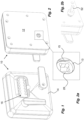
- the code lock 16 is bolted to a base plate 18, which in turn is bolted to a door or the like, preferably with bolts from the inside of the door going through the back plate 12.
- the code lock 16 is provided with a handle 20 and a keypad 22, wherein the interior of the code lock is arranged with a mechanism that blocks movement of the handle 20 until a correct sequence of keys are entered with the keypad 22.
- the front cover 14 of the housing is in that regard arranged with openings for the handle and the keypad but is covering and protecting the rest of the code lock as seen in Fig. 1 .
- the code lock 16 is further arranged with an actuating pin 24, Figs. 5 and 8 , extending through a passage of the base plate 18, which actuating pin 24 is operably connected to the handle 20 of the code lock.
- Bolts (not shown) are threaded into threaded holes 42 in the hub 32 and clamp the hub 32 and the bracket 39 to the base plate 18.
- the base plate 18 is arranged with a passage 44, Figs. 5 and 6 , through which the axle 26 extends.
- the axle 26 is provided with an annular ledge 46 that when the blocking device 10 is assembled is positioned inside the hub 32 and is pushed against an inner surface of the first end wall 30 by a compression spring 48 having one end acting on the annular ledge 46. The other end of the compression spring 48 is in contact with the bushing 34.
- the arrangement enables a movement of the handle 28 and the axle 26 towards the door against the force of the compression spring 48, as will be described below.
- the end of the axle 26 is provided with a seat 50 at its inner end, Fig. 7 , which seat 50 is designed to fit together and act with a shaft 52, Fig. 2b , which shaft 52 is an actuating part of a locking arrangement for locking the door or the like to which the blocking device 10 is attached.
- the axle 26 is provided with an annular groove 54, forming a first blocking element.
- the end of the axle 26 is also arranged with planar surfaces 55 of removed material.
- the plate-shaped section 78 is arranged with a keyhole shaped passage 82, Figs. 7 and 8 , forming a part of a second blocking element with the blocking sledge 76.
- the narrower part of the keyhole passage 82 has a width generally corresponding to the diameter of the annular groove 54 of the axle 26, while the wider part of the keyhole passage 82 has a width larger than the general diameter of the axle 26.
- the blocking sledge 76 is further arranged with a first seat 84 extending in the longitudinal direction of the blocking sledge 76, Fig. 7 .
- a generally plate-shape blocking plate 86 is designed to fit into the first seat 84 and to be movable in the longitudinal direction of the blocking sledge 76.
- the blocking plate 86 is arranged with a passage 88 in which the second shaft 72 of the torque arm 68 fits, Fig. 8 .
- the blocking plate 86 is further arranged with an elongated groove 90 being inclined at an angle in relation to the longitudinal direction of the blocking sledge 76.
- a second seat 92 is provided in the blocking sledge 76, extending transversal to the longitudinal direction of the blocking sledge 76.
- the blocking device 10 is bolted to a door or the like such that the passage 13 of the back plate 12 is placed in relation to an actuation shaft or axle 52 of the locking system is aligned with the longitudinal direction of the axle 26 of the blocking device 10, Fig 2b .
- the axle 26 In the initial inactivated position, the axle 26 is in its retracted position by the compression spring 48 that pushes it the outward direction.
- the annular groove 54 In this position of the axle 26, the annular groove 54 is in the same plane as the plate-shaped section 78 of the blocking sledge 76.
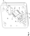
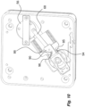
- the blocking sledge 76 is in its forwardmost position whereby the narrow section of the keyhole 82 has been pushed into the annular groove 54 of the axle 26 by the compression springs 93 as seen in Figs. 4 and 10 .
- the blocking plate 86 is in its forwardmost position whereby the pin 96 of the blocker 94 is in the rearmost position in the inclined groove 90 of the blocking plate 86.
- the torque plate 56 may be rotated by electrically driven actuators such as a stepper motor or a linear actuator.
- a suitable power source is arranged to provide the actuators with power to operate them.
- suitable communication devices may be utilised that preferably are provided with authorisation elements so that only dedicated communication devices may operate the actuators.
- first and the second blocking elements may have alternative designs that provide form-locking functions.
- the axle 26 may be provided with a transversal hole or passage and the blocking sledge 76 may be provided with a pin or shaft extending in the sliding direction wherein the pin in the blocking position is positioned inside the passage and wherein the pin is moved out of the passage in the release position.
- the end section of the locking bolt 114 is designed to engage with a recess, seat, ledge or the like fixed structure arranged on a fixed structure of the compartment, such as a door frame or the floor of the compartment.
- a fixed structure of the compartment such as a door frame or the floor of the compartment.
- the end of the locking bolt is arranged with an inclined surface 118, enabling a movement from an extended position to a retracted position when the locking bolt during a closing action hits the fixed structure with its inclined surface.
- the locking bolt may have a more planar or convex end surface.
- the end section 116 is also arranged with a generally tubular element 120 surrounding the locking bolt 114, which element is arranged to prevent attempts to saw or cut off the locking bolt in order to get access to the interior of the compartment.
- the slide bearing 128 is placed in a generally tubular bearing housing 130 and the unit is retained in the bearing block124 by an end plate 132 with a central passage 134 for the shaft at one end and a circlip 136 in a groove 138 in the cylindrical passage 126 of the bearing block 124 at the opposite end.
- the diameter of the cylindrical passage 126 of the bearing block 124 and the diameter of the bearing housing 130 are chosen such that there is a gap or play 140 between the bearing block 124 and the bearing housing 130, enabling movement in the transversal direction of the locking bolt. This is an advantage if the door for some reason is not completely aligned in relation to the frame and therefore the locking bolt is not completely aligned with the locking recess, which could provide difficulties during a locking action. With the "floating" design of the locking bolt being movable transversally, any misalignment would be handled.
- the locking mechanism 112 further comprises a transmission that incorporates an attachment block 142 that comprises a central passage through which the shaft 122 of the locking bolt passes.
- the attachment block 142 is provided with a locking element such as a lock screw (not shown) with which the attachment block 142 may be attached to the shaft 122 at a suitable point along its length.
- a compression spring 144 is provided between an upper end of the attachment block 142 and the end plate 132 of the upper bearing block 124, where the compression spring 144 surrounds the shaft 122.
- the attachment block 142 is further arranged with a second roller bearing 146 journalled on a shaft of the attachment block 142. The second roller bearing 146 is arranged to fit into an elongated groove 148 of an elongated pressure arm 150 of the transmission.
- the locking arrangement 100 is intended to function as follows.
- the handle of the blocking device is operated as described above and turned clockwise as seen from outside the door, the arm 166 is also turned. Since the first roller bearing 170 is in contact with the lever 160, the turning of the arm 166 will cause the lever 160 to pivot towards the locking bolt 114, Fig. 22 .
- the pressure arm 150 is pivotally attached to the lever 160, it will also be moved and its third roller bearing 152 will follow the track 154, pivoting the pressure arm 150 upwards.
- a holding element may be provided for holding the locking bolt in the retracted position.
- the arm 166 When the handle of the blocking device 10 is moved back to its initial position, the arm 166 is also moved back to its initial position and so are the rest of the components of the locking mechanism 112.
- the locking bolt 114 is also returned to its extended position by the force of the compression spring 144 acting on the attachment block 142.
- the pusher plate is further arranged with a pin 200 that is intended to cooperate with a groove 202, Fig. 25 , on the inside of the stop ledge 194.
- the lower guide 192 is provided with an inclined surface 204, the function of which will be described below.
- An elongated locking arm 206 is further provided that is pivotally attached to the base plate via a pillar 207 at a point nearly in the middle of the extension of the locking arm 206. In this regard, the locking arm 206 may be pivotally attached with a low friction bearing.
- a first pin 208 is attached and arranged to be in contact with the end of the pusher plate 196 and the fifth roller bearing 198.
- An upper end of the locking arm 206 is provided with a second pin 210, which is arranged to be in contact with the lever 160 as will be described.
- the second pin 210 may in this regard be provided with a roller bearing for low friction.
- the shaft 122 of the locking bolt 114 is arranged with a locking ring 214, Fig. 24 , whereby the attachment block 142 acts against the locking ring during retraction of the locking bolt.
- This also enables a manual retraction of the locking bolt by a person inside the compartment, by merely gripping the knob 123 and lifting the locking bolt.
- a groove 216 is arranged in the base plate and the attachment block 142 is arranged with a further roller bearing on the opposite side of the second roller bearing 146, running in the groove 216, which provides an increased guide for the attachment block 142 during its movement, preventing any twisting of the attachment block 142 around the shaft 122 since it now doesn't have to be fixedly attached to the shaft 122.
- the variant is intended to function as follows.
- the locking bolt 114 is extended and the transmission is positioned as described above.
- the return shaft 180 is in a retracted position by the contact with the end of the return shaft against a fixed structure, such as a door frame.
- the pusher plate 196 is resting on the inclined surface 204 of the lower guide 192 and the locking arm 206 is biased by a torsion spring (not shown) arranged between the locking arm 206 and the pillar.
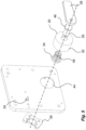
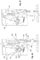
- the components of the locking arrangement are moved in the same manner as above. Further, the lever 160 will during the movement come in contact with the second pin 210 of the locking arm 206 and pivot it so that the lower end of the locking arm 206 is moved towards the pusher. This is enabled in that the pusher plate 196 is inclined downwards, resting on the inclined surface 204 of the lower guide 192 as seen in Fig. 24 . As seen in Fig. 28 , when the locking bolt is in the retracted position, it cannot be pulled out due to that the lever 160 has somewhat passed the vertical position and will together with the rest of the transmission block the locking bolt 114.
- the return shaft 180 When now the door is opened, the return shaft 180 will be moved to the extended position as seen in Fig. 28 by the force of the compression spring 184. The movement of the return shaft 180 will further cause the pusher plate 196 to be moved from the inclined position to a horizontal position, sliding along the guides 190, 192, whereby the pin 200 of the pusher plate 196 will enter the groove 202 of the stop ledge 194.
- the return shaft 180 will come in contact with the fixed structure and will be pushed into the retracted position. This will in turn cause the pusher plate 196 to move towards and come in contact with the first pin 208 of the locking arm, Fig. 25 .
- the pusher plate 196 is guided by its pin 200 through an extension of the groove 202, 202', as seen in Fig. 25 .
- the pusher plate is further secured in this position by a spring-loaded ball 212 placed in the lower guide 192, seen in Fig. 24 . Further movement will cause the locking arm 206 to pivot, whereby its second pin 210 will act on the lever 160 and pivot it towards its initial position.
- the transmission is no longer locked and the force of the compression spring 146 will urge the locking bolt back to its extended, locking, position and all the components will return to their initial positions.
- the locking arm 206 will also return to its initial position by the torque spring and leave the contact with the fifth roller bearing 198 of the pusher plate 196.
- the pin 200 of the pusher plate 196 has now left the groove 202' and the pusher plate 196 is returned to its inclined position against the inclined surface 204.
- Figures 29 - 37 show another variant of the return mechanism 100.
- the same components have the same reference numerals as the previous variant.
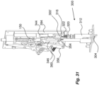
- This variant is provided with another variant of a return mechanism for the locking bolt. It comprises an elongated return shaft 300 arranged slidable in a direction generally parallel to the direction of movement of the locking bolt 114.
- the return shaft is arranged with an inclined end surface 302 intended to come in contact with a fixed structure of the compartment when the door is closed.
- the return shaft is arranged with an overload mechanism comprising an end bolt 304 having the inclined end surface 302, Fig. 30 .
- the end bolt 304 is arranged with a threaded hole in which a threaded section of a piston 306 is connected.
- the upper end of the piston 306 is placed in a cylinder 308.
- a spring 310 is arranged surrounding the piston and is pretensioned between a rear end surface of the end bolt 304 and a front surface of the cylinder 308.
- the cylinder-piston arrangement is placed in a sleeve 312, which sleeve 312 is arranged with an upper contact part 314 to be in contact with an upper part 300' of the return shaft.
- the return shaft 100 may extend into the locking arrangement, but may also be divided so that there is a gap between the lower part and the upper part of the return shaft 300.
- An advantage with the gap is that the travel of the return shaft 300 may be adjusted to the specific door arrangement and the distance between the lower edge of the door and the fixed structure surrounding the door, such as a door frame or the floor of the compartment.
- the upper part 300' of the return shaft is slidably journalled in a bearing block 316.
- the bearing block 316 may be attached to an assembly block 318 which in turn is attached to the base plate 110.
- a nut 320 may be threaded onto the upper part of the return shaft 300 and a compression spring 322 is arranged between the nut 320 and a downward surface of the bearing block 316 for urging the upper part 300' of the return shaft 300 in the downward direction.
- the nut 320 enables adjustment of the tension and thus the force of the compression spring 322.
- the upper end of the return shaft is attached to a pusher 324.
- the upper part of the pusher 324 is arranged with a through-hole 326, which is cooperating with a pin 328, extending generally transversal to the direction of the return shaft 300 and thus the sliding direction of the pusher 324.
- the pin 328 is arranged in an elongated hole 330 in an assembly block 332 and is provided with an enlargement 334 fitting in a recess 336 surrounding the elongated hole 330 on the backside of the assembly block 332, Fig. 34 , enabling a sliding action of the pin 328.
- the pin 328 extends through a hole in a follower 338 so that the follower 338 and the pusher 324 are slidably connected.
- the arrangement provides a certain turning of the follower 338 as will be described.
- a first roller bearing 340 is attached on the backside of the follower 338.
- the first roller bearing 340 is arranged to fit into a recess 342 in the assembly block 332 arranged above the elongated hole 330.
- the side surfaces of the recess 342 are such that the left side, as seen in Fig. 34 extends in a generally straight line with the elongated hole 330.
- the side surface transforms into a curved top surface wider than the elongated hole so that the right wall extends back with an inclination in relation to the direction of the elongated hole 330.
- the function of this design will be explained below.
- the follower 338 with the first roller bearing 340 is further biased towards the left side surface of the recess 342 by a leaf spring 344 pressing on the right side surface of the follower 338 as seen in Fig. 32 .
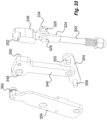
- a generally T-shaped pulling arm 346 is pivotally attached to the assembly block 332 via a shaft 348 at the left upper part as seen in Fig. 33 .
- the right upper part of the pulling arm 346 is pivotally connected to the follower 338 via a pin 350 fitting in a recess 352 of the follower 338.
- the lower end of the pulling arm 346 is in turn pivotally connected to one end of an elongated tension rod 354 via a shaft 355.
- the other end of the tension rod 354 is pivotally attached to one end of an elongated actuator arm 356 via a shaft 358.
- the actuator arm 356 is further pivotally journalled on a shaft 360 attached to the base plate 110 about midway along the extension of the actuator arm 356.
- the arrangement is intended to function as follows.
- the locking bolt 122 is retracted. This is done in that a handle or the like is turned on the outside whereby the hub 164 with its arm 166 has been turned to a vertical downward position.
- the fourth roller bearing 366 of the actuator arm 356 then acts on the lever 160, which will pivot towards the locking bolt 122.
- the pressure arm 150 since the pressure arm 150 is pivotally attached to the lever 160, it will also be moved and its third roller bearing 152 will follow the track 154, pivoting the pressure arm 150 upwards.
- the inclined end surface 302 of the return shaft 300 When the door is closed the inclined end surface 302 of the return shaft 300 will strike against a fixed structure surrounding the door such as a door frame or the floor of the compartment. The inclination of the end surface 302 will cause the return shaft 300 to move upwards against the force of the compression spring 322. If the door and the door frame for some reason are misaligned so that the return shaft may be pushed too far upwards, risking damage to the mechanism, the overload mechanism will come in action, whereby the end bolt 304 will move upwards in the sleeve 312, thereby compressing the spring of the cylinder-piston arrangement, thereby taking up any excessive movement of the return shaft 300.
- the pin 408 extends through a hole 410 in a generally plate-shaped follower 412, wherein the follower is arranged generally perpendicular to the extension.
- the hole 410 is somewhat larger than the diameter of the pin 408.
- An upper part of the pin fits into a hole 414 in a downward end surface of the assembly block 332.
- the follower 412 is attached to the assembly plate 398 via pins 416 extending into elongated grooves 418 in the assembly plate 398 and in a holding plate 420 attached to the ledge 156, allowing a movement of the follower 412 in the direction of the extension and also a slight turning around the pins 416 as will be described.
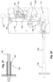
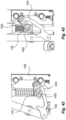
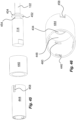
- a blocking arrangement may be used, Figs. 44 and 45 .
- a cylindrical bushing 440 is fixedly attached to a plate 442 that in turn is attached to a downward surface of a door or the like openable component.
- the locking bolt 114 is provided with a cylindrical sheath 444 that is movable along the locking bolt, wherein the lower part of the locking bolt 114 may extend out of a lower end of the sheath 444.
- the shaft will pull the locking bolt upwards.
- the diameter of the locking bolt is such that it will pass the inwardly directed protrusion 460 and be move in contact with the locking plate. Since the upper end surface of the locking bolt is parallel with the locking plate 452, the latter will not tilt and the whole assembly can be moved to the unlocking position through the bushing.
Landscapes
- Engineering & Computer Science (AREA)
- Mechanical Engineering (AREA)
- Lock And Its Accessories (AREA)
- Operating, Guiding And Securing Of Roll- Type Closing Members (AREA)
- Specific Sealing Or Ventilating Devices For Doors And Windows (AREA)
Claims (7)
- Agencement de verrouillage destiné à verrouiller de manière libérable une porte d'un compartiment, l'agencement de verrouillage comprenant :- un boulon de verrouillage (114) mobile entre une position de verrouillage étendue et une position de déverrouillage rétractée ;- un actionneur (162) fonctionnellement relié à un élément d'ouverture, l'actionneur pouvant tourner entre une position initiale et une position activée ;- une transmission (146, 150, 154, 160, 166) disposée entre l'actionneur (162) et le boulon de verrouillage (114), la transmission étant conçue pour déplacer ledit boulon de verrouillage (114) entre la position étendue et la position rétractée lorsque l'actionneur est tourné, ladite transmission comprenant- un levier (160) disposé de manière pivotante et en contact avec l'actionneur ;- un bras de pression (150) fixé de manière pivotante au niveau d'une extrémité au levier et relié fonctionnellement audit boulon de verrouillage ;- la rotation de l'actionneur amenant le levier à pivoter et le bras de pression à agir sur ledit boulon de verrouillage pour faire passer ledit boulon de verrouillage de la position étendue à la position rétractée,ledit actionneur (162) comprenant un bras (166), un premier roulement à rouleaux (170) tourillonné au niveau d'une extrémité libre dudit bras (166), lequel premier roulement à rouleaux (170) étant disposé en contact avec une surface dudit levier (160) et se déplaçant le long de celle-ci,ledit bras de pression (150) étant pourvu d'une rainure allongée (148), le boulon de verrouillage (114) étant pourvu d'un bloc de fixation fixé audit boulon de verrouillage, ledit bloc de fixation étant pourvu d'un deuxième roulement à rouleaux (146) conçu pour se déplacer dans ladite rainure,ladite transmission comprenant en outre- une surface de support (156) pourvue d'un rail (154) et une seconde extrémité dudit bras de pression étant conçue pour être en contact avec ledit rail et s'y déplacer.
- Agencement de verrouillage selon la revendication 1, ladite seconde extrémité étant pourvue d'un troisième roulement à rouleaux (152) se déplaçant dans ledit rail (154) .
- Agencement de verrouillage selon la revendication 1 ou 2, ledit boulon de verrouillage étant pourvu d'un ressort de compression (144) conçu pour solliciter ledit boulon de verrouillage (114) dans la position étendue.
- Agencement de verrouillage selon l'une quelconque des revendications précédentes, comprenant en outre des blocs d'appui (124) conçus pour soutenir ledit boulon de verrouillage (114).
- Agencement de verrouillage selon la revendication 4, lesdits blocs d'appui comprenant des appuis coulissants (128) à travers lesquels le boulon de verrouillage est supporté de manière coulissante, et lesdits appuis coulissants étant disposés dans lesdits blocs d'appui avec du jeu dans les directions transversales.
- Agencement de verrouillage selon l'une quelconque des revendications précédentes, l'agencement de verrouillage comprenant en outre :- un mécanisme de rappel (100) agissant fonctionnellement sur ladite transmission (146, 150, 154, 160, 166) lorsque ledit boulon de verrouillage (114) est dans sa position rétractée, lequel mécanisme de rappel (100) étant pourvu d'un élément qui, lors de la fermeture d'une porte, est mis en contact avec une structure fixe entourant la porte.
- Agencement de verrouillage selon la revendication 6, ledit mécanisme de rappel (110) comprenant- un arbre de rappel coulissant (180) s'étendant hors de la porte lorsque la porte est en position ouverte, une extrémité intérieure étant en contact avec ledit levier (160) de sorte qu'un mouvement dudit arbre de rappel (180) vers la position rétractée amène le levier (160) à pivoter pour revenir à sa position initiale.
Applications Claiming Priority (2)
| Application Number | Priority Date | Filing Date | Title |
|---|---|---|---|
| SE2050755 | 2020-06-24 | ||
| PCT/SE2021/050633 WO2021262079A1 (fr) | 2020-06-24 | 2021-06-24 | Dispositif de blocage et de fermeture automatique |
Publications (3)
| Publication Number | Publication Date |
|---|---|
| EP4172436A1 EP4172436A1 (fr) | 2023-05-03 |
| EP4172436C0 EP4172436C0 (fr) | 2025-01-29 |
| EP4172436B1 true EP4172436B1 (fr) | 2025-01-29 |
Family
ID=76797065
Family Applications (1)
| Application Number | Title | Priority Date | Filing Date |
|---|---|---|---|
| EP21737828.0A Active EP4172436B1 (fr) | 2020-06-24 | 2021-06-24 | Agencement de verrouillage |
Country Status (3)
| Country | Link |
|---|---|
| EP (1) | EP4172436B1 (fr) |
| WO (1) | WO2021262079A1 (fr) |
| ZA (2) | ZA202304546B (fr) |
Families Citing this family (1)
| Publication number | Priority date | Publication date | Assignee | Title |
|---|---|---|---|---|
| CN115220111B (zh) * | 2022-07-20 | 2025-08-22 | 苏州思萃融合基建技术研究所有限公司 | 一种井盖水浸监测终端及其安装方法 |
Citations (1)
| Publication number | Priority date | Publication date | Assignee | Title |
|---|---|---|---|---|
| EP0306028A2 (fr) * | 1987-09-02 | 1989-03-08 | Hörmann-Genk Nv | Vantail de portail ou vantail de porte composé d'un ou de plusieurs parties et muni d'une serrure à barre |
Family Cites Families (8)
| Publication number | Priority date | Publication date | Assignee | Title |
|---|---|---|---|---|
| FI79170C (fi) * | 1986-12-29 | 1989-11-10 | Waertsilae Oy Ab | Arrangemang vid ett doerrlaos. |
| GB2265936A (en) * | 1992-04-04 | 1993-10-13 | Ford Motor Co | A door lock with disabling means for the handle |
| US6705136B2 (en) * | 2001-05-30 | 2004-03-16 | Dave Porter | Storage compartment security system |
| US6843084B2 (en) * | 2001-05-30 | 2005-01-18 | Dave Porter | Storage compartment security system |
| FI120109B (fi) * | 2006-05-02 | 2009-06-30 | Abloy Oy | Lukkorunko |
| US20090217718A1 (en) * | 2008-01-15 | 2009-09-03 | James David Porter | Intermodal physical security device |
| EP3099870B1 (fr) * | 2014-01-31 | 2019-11-13 | Cisa S.p.a. | Dispositif d'actionnement externe, associable avec poignées, barres anti-panique, etc. |
| FI128706B (fi) * | 2015-09-18 | 2020-10-30 | Abloy Oy | Lukkorunko |
-
2021
- 2021-06-24 EP EP21737828.0A patent/EP4172436B1/fr active Active
- 2021-06-24 WO PCT/SE2021/050633 patent/WO2021262079A1/fr not_active Ceased
-
2023
- 2023-04-19 ZA ZA2023/04546A patent/ZA202304546B/en unknown
-
2024
- 2024-04-15 ZA ZA2024/02893A patent/ZA202402893B/en unknown
Patent Citations (1)
| Publication number | Priority date | Publication date | Assignee | Title |
|---|---|---|---|---|
| EP0306028A2 (fr) * | 1987-09-02 | 1989-03-08 | Hörmann-Genk Nv | Vantail de portail ou vantail de porte composé d'un ou de plusieurs parties et muni d'une serrure à barre |
Also Published As
| Publication number | Publication date |
|---|---|
| ZA202402893B (en) | 2025-07-30 |
| EP4172436A1 (fr) | 2023-05-03 |
| EP4172436C0 (fr) | 2025-01-29 |
| ZA202304546B (en) | 2024-08-28 |
| WO2021262079A1 (fr) | 2021-12-30 |
Similar Documents
| Publication | Publication Date | Title |
|---|---|---|
| US8047582B1 (en) | Electro-mechanical lock | |
| US5419597A (en) | Power-actuated motor-vehicle door latch with antitheft override | |
| US4974886A (en) | Motor-vehicle door latch with antitheft override | |
| US20120175896A1 (en) | Vehicle door latch | |
| EP1953317B1 (fr) | Un véhicule à moteur avec un ensemble de loquet double | |
| US5899508A (en) | Double locking vehicle door latch | |
| US7698918B2 (en) | Interchangeable lock operable in fail safe or fail secure modes | |
| US6082791A (en) | Electric strike | |
| AU2012283731B2 (en) | A lock assembly | |
| US7461872B2 (en) | Motorized swing bolt lock | |
| US7614669B2 (en) | Interchangeable lock operable in fail safe or fail secure modes | |
| MXPA06004770A (es) | Seguro de puerta con operacion de manija controlable. | |
| KR101356668B1 (ko) | 록 기구 | |
| DK3140478T3 (en) | ELECTROMECHANICAL LOCKING UNIT | |
| US10392831B2 (en) | Dead-latching slam bolt lock | |
| EP3511492B1 (fr) | Mecanisme de verrouillage pour porte de vehicule de fret | |
| EP0141020B1 (fr) | Equipement de manipulation pour portes | |
| US5520423A (en) | Anti-burst latch | |
| US5062669A (en) | Secured locking device | |
| EP4172436A1 (fr) | Dispositif de blocage et de fermeture automatique | |
| US7066500B2 (en) | Vehicle door lock | |
| US11542726B2 (en) | Surface mounted single solenoid electric strike | |
| US7784315B2 (en) | Locking device for truck | |
| US6729072B1 (en) | Integral latch and drive system for a powered sliding door | |
| US20250230686A1 (en) | Lock |
Legal Events
| Date | Code | Title | Description |
|---|---|---|---|
| STAA | Information on the status of an ep patent application or granted ep patent |
Free format text: STATUS: UNKNOWN |
|
| STAA | Information on the status of an ep patent application or granted ep patent |
Free format text: STATUS: THE INTERNATIONAL PUBLICATION HAS BEEN MADE |
|
| PUAI | Public reference made under article 153(3) epc to a published international application that has entered the european phase |
Free format text: ORIGINAL CODE: 0009012 |
|
| STAA | Information on the status of an ep patent application or granted ep patent |
Free format text: STATUS: REQUEST FOR EXAMINATION WAS MADE |
|
| 17P | Request for examination filed |
Effective date: 20230120 |
|
| AK | Designated contracting states |
Kind code of ref document: A1 Designated state(s): AL AT BE BG CH CY CZ DE DK EE ES FI FR GB GR HR HU IE IS IT LI LT LU LV MC MK MT NL NO PL PT RO RS SE SI SK SM TR |
|
| DAV | Request for validation of the european patent (deleted) | ||
| DAX | Request for extension of the european patent (deleted) | ||
| STAA | Information on the status of an ep patent application or granted ep patent |
Free format text: STATUS: EXAMINATION IS IN PROGRESS |
|
| 17Q | First examination report despatched |
Effective date: 20231206 |
|
| GRAP | Despatch of communication of intention to grant a patent |
Free format text: ORIGINAL CODE: EPIDOSNIGR1 |
|
| STAA | Information on the status of an ep patent application or granted ep patent |
Free format text: STATUS: GRANT OF PATENT IS INTENDED |
|
| INTG | Intention to grant announced |
Effective date: 20240812 |
|
| GRAS | Grant fee paid |
Free format text: ORIGINAL CODE: EPIDOSNIGR3 |
|
| GRAA | (expected) grant |
Free format text: ORIGINAL CODE: 0009210 |
|
| STAA | Information on the status of an ep patent application or granted ep patent |
Free format text: STATUS: THE PATENT HAS BEEN GRANTED |
|
| AK | Designated contracting states |
Kind code of ref document: B1 Designated state(s): AL AT BE BG CH CY CZ DE DK EE ES FI FR GB GR HR HU IE IS IT LI LT LU LV MC MK MT NL NO PL PT RO RS SE SI SK SM TR |
|
| REG | Reference to a national code |
Ref country code: GB Ref legal event code: FG4D |
|
| REG | Reference to a national code |
Ref country code: CH Ref legal event code: EP |
|
| REG | Reference to a national code |
Ref country code: DE Ref legal event code: R096 Ref document number: 602021025433 Country of ref document: DE |
|
| REG | Reference to a national code |
Ref country code: IE Ref legal event code: FG4D |
|
| U01 | Request for unitary effect filed |
Effective date: 20250218 |
|
| U07 | Unitary effect registered |
Designated state(s): AT BE BG DE DK EE FI FR IT LT LU LV MT NL PT RO SE SI Effective date: 20250224 |
|
| PG25 | Lapsed in a contracting state [announced via postgrant information from national office to epo] |
Ref country code: RS Free format text: LAPSE BECAUSE OF FAILURE TO SUBMIT A TRANSLATION OF THE DESCRIPTION OR TO PAY THE FEE WITHIN THE PRESCRIBED TIME-LIMIT Effective date: 20250429 |
|
| PG25 | Lapsed in a contracting state [announced via postgrant information from national office to epo] |
Ref country code: PL Free format text: LAPSE BECAUSE OF FAILURE TO SUBMIT A TRANSLATION OF THE DESCRIPTION OR TO PAY THE FEE WITHIN THE PRESCRIBED TIME-LIMIT Effective date: 20250129 |
|
| PG25 | Lapsed in a contracting state [announced via postgrant information from national office to epo] |
Ref country code: ES Free format text: LAPSE BECAUSE OF FAILURE TO SUBMIT A TRANSLATION OF THE DESCRIPTION OR TO PAY THE FEE WITHIN THE PRESCRIBED TIME-LIMIT Effective date: 20250129 |
|
| PGFP | Annual fee paid to national office [announced via postgrant information from national office to epo] |
Ref country code: GB Payment date: 20250618 Year of fee payment: 5 |
|
| PG25 | Lapsed in a contracting state [announced via postgrant information from national office to epo] |
Ref country code: IS Free format text: LAPSE BECAUSE OF FAILURE TO SUBMIT A TRANSLATION OF THE DESCRIPTION OR TO PAY THE FEE WITHIN THE PRESCRIBED TIME-LIMIT Effective date: 20250529 Ref country code: NO Free format text: LAPSE BECAUSE OF FAILURE TO SUBMIT A TRANSLATION OF THE DESCRIPTION OR TO PAY THE FEE WITHIN THE PRESCRIBED TIME-LIMIT Effective date: 20250429 |
|
| PG25 | Lapsed in a contracting state [announced via postgrant information from national office to epo] |
Ref country code: HR Free format text: LAPSE BECAUSE OF FAILURE TO SUBMIT A TRANSLATION OF THE DESCRIPTION OR TO PAY THE FEE WITHIN THE PRESCRIBED TIME-LIMIT Effective date: 20250129 |
|
| PG25 | Lapsed in a contracting state [announced via postgrant information from national office to epo] |
Ref country code: GR Free format text: LAPSE BECAUSE OF FAILURE TO SUBMIT A TRANSLATION OF THE DESCRIPTION OR TO PAY THE FEE WITHIN THE PRESCRIBED TIME-LIMIT Effective date: 20250430 |
|
| U20 | Renewal fee for the european patent with unitary effect paid |
Year of fee payment: 5 Effective date: 20250617 |
|
| PG25 | Lapsed in a contracting state [announced via postgrant information from national office to epo] |
Ref country code: SM Free format text: LAPSE BECAUSE OF FAILURE TO SUBMIT A TRANSLATION OF THE DESCRIPTION OR TO PAY THE FEE WITHIN THE PRESCRIBED TIME-LIMIT Effective date: 20250129 |
|
| PG25 | Lapsed in a contracting state [announced via postgrant information from national office to epo] |
Ref country code: CZ Free format text: LAPSE BECAUSE OF FAILURE TO SUBMIT A TRANSLATION OF THE DESCRIPTION OR TO PAY THE FEE WITHIN THE PRESCRIBED TIME-LIMIT Effective date: 20250129 |
|
| PG25 | Lapsed in a contracting state [announced via postgrant information from national office to epo] |
Ref country code: SK Free format text: LAPSE BECAUSE OF FAILURE TO SUBMIT A TRANSLATION OF THE DESCRIPTION OR TO PAY THE FEE WITHIN THE PRESCRIBED TIME-LIMIT Effective date: 20250129 |
|
| PLBE | No opposition filed within time limit |
Free format text: ORIGINAL CODE: 0009261 |
|
| STAA | Information on the status of an ep patent application or granted ep patent |
Free format text: STATUS: NO OPPOSITION FILED WITHIN TIME LIMIT |
|
| REG | Reference to a national code |
Ref country code: CH Ref legal event code: L10 Free format text: ST27 STATUS EVENT CODE: U-0-0-L10-L00 (AS PROVIDED BY THE NATIONAL OFFICE) Effective date: 20251210 |
|
| 26N | No opposition filed |
Effective date: 20251030 |
|
| REG | Reference to a national code |
Ref country code: CH Ref legal event code: H13 Free format text: ST27 STATUS EVENT CODE: U-0-0-H10-H13 (AS PROVIDED BY THE NATIONAL OFFICE) Effective date: 20260127 |
|
| PG25 | Lapsed in a contracting state [announced via postgrant information from national office to epo] |
Ref country code: MC Free format text: LAPSE BECAUSE OF FAILURE TO SUBMIT A TRANSLATION OF THE DESCRIPTION OR TO PAY THE FEE WITHIN THE PRESCRIBED TIME-LIMIT Effective date: 20250129 |
|
| PG25 | Lapsed in a contracting state [announced via postgrant information from national office to epo] |
Ref country code: IE Free format text: LAPSE BECAUSE OF NON-PAYMENT OF DUE FEES Effective date: 20250624 |
|
| PG25 | Lapsed in a contracting state [announced via postgrant information from national office to epo] |
Ref country code: CH Free format text: LAPSE BECAUSE OF NON-PAYMENT OF DUE FEES Effective date: 20250630 |