EP4172525B1 - Dispositif de raccord et de retenue de tuyau - Google Patents
Dispositif de raccord et de retenue de tuyau Download PDFInfo
- Publication number
- EP4172525B1 EP4172525B1 EP20751661.8A EP20751661A EP4172525B1 EP 4172525 B1 EP4172525 B1 EP 4172525B1 EP 20751661 A EP20751661 A EP 20751661A EP 4172525 B1 EP4172525 B1 EP 4172525B1
- Authority
- EP
- European Patent Office
- Prior art keywords
- pipe
- gripper
- coupling
- restraining device
- support body
- Prior art date
- Legal status (The legal status is an assumption and is not a legal conclusion. Google has not performed a legal analysis and makes no representation as to the accuracy of the status listed.)
- Active
Links
Images






Classifications
-
- F—MECHANICAL ENGINEERING; LIGHTING; HEATING; WEAPONS; BLASTING
- F16—ENGINEERING ELEMENTS AND UNITS; GENERAL MEASURES FOR PRODUCING AND MAINTAINING EFFECTIVE FUNCTIONING OF MACHINES OR INSTALLATIONS; THERMAL INSULATION IN GENERAL
- F16L—PIPES; JOINTS OR FITTINGS FOR PIPES; SUPPORTS FOR PIPES, CABLES OR PROTECTIVE TUBING; MEANS FOR THERMAL INSULATION IN GENERAL
- F16L21/00—Joints with sleeve or socket
- F16L21/08—Joints with sleeve or socket with additional locking means
-
- F—MECHANICAL ENGINEERING; LIGHTING; HEATING; WEAPONS; BLASTING
- F16—ENGINEERING ELEMENTS AND UNITS; GENERAL MEASURES FOR PRODUCING AND MAINTAINING EFFECTIVE FUNCTIONING OF MACHINES OR INSTALLATIONS; THERMAL INSULATION IN GENERAL
- F16L—PIPES; JOINTS OR FITTINGS FOR PIPES; SUPPORTS FOR PIPES, CABLES OR PROTECTIVE TUBING; MEANS FOR THERMAL INSULATION IN GENERAL
- F16L21/00—Joints with sleeve or socket
- F16L21/02—Joints with sleeve or socket with elastic sealing rings between pipe and sleeve or between pipe and socket, e.g. with rolling or other prefabricated profiled rings
- F16L21/04—Joints with sleeve or socket with elastic sealing rings between pipe and sleeve or between pipe and socket, e.g. with rolling or other prefabricated profiled rings in which sealing rings are compressed by axially-movable members
-
- F—MECHANICAL ENGINEERING; LIGHTING; HEATING; WEAPONS; BLASTING
- F16—ENGINEERING ELEMENTS AND UNITS; GENERAL MEASURES FOR PRODUCING AND MAINTAINING EFFECTIVE FUNCTIONING OF MACHINES OR INSTALLATIONS; THERMAL INSULATION IN GENERAL
- F16L—PIPES; JOINTS OR FITTINGS FOR PIPES; SUPPORTS FOR PIPES, CABLES OR PROTECTIVE TUBING; MEANS FOR THERMAL INSULATION IN GENERAL
- F16L25/00—Construction or details of pipe joints not provided for in, or of interest apart from, groups F16L13/00 - F16L23/00
- F16L25/14—Joints for pipes of different diameters or cross-section
Definitions
- the present device belongs to the field of establishing restrained pipe connections using pipe coupling and restraining devices.
- the present subject matter discloses a pipe coupling and restraining device that may be used for establishing longitudinally restrained pipe connections of multi-diameter and/or multiple materials pipes while allowing for axial misalignments between both ends of the device.
- the present disclosure relates to a pipe coupling and restraining device for connecting to a pipe wherein restraining and sealing are ensured, the installation of which being simpler and easier to perform.
- the present document discloses a pipe coupling and restraining device for:
- the pipe coupling and restraining device can be a gate valve, a "T" socket, a socket bend, or a fixation flange, among others.
- the pipe coupling is preferably made of cast iron.
- the pipe coupling contains two axial ends, one of them is turned to the device to be coupled to the pipe and the other end is turned to the pipe to be coupled.
- a coupling and restraining device for connecting to a pipe, comprising:
- a pipe coupling and restraining device for connecting to a pipe, said pipe defining a longitudinal axis, comprising:
- the wedge-shaped segment comprises interdigitated fingers on a face of the support body for meshing with corresponding interdigitated fingers of two neighbouring wedge-shaped segments in order to support the annular seal as a circumferentially uninterrupted surface, as if the wedge-shaped segments formed a contiguous annular surface around the pipe to support the annular seal without full longitudinal interruptions of such support.
- said fingers have slack interdigitating with the fingers of the adjacent segment such that adjacent segments may oscillate between each other while the fingers are still interdigitated to accommodate a pipe imperfection or misalignment.
- the sleeve and clamping ring comprise bolt fixation tabs for tightening the sleeve and clamping ring against each other.
- first and second annular abutment surfaces are arranged to be facing against each other in an axial direction such that the first and second annular abutment surfaces engage, when tightened one against the other, to compress the collar assembly against the pipe and against the second annular abutment surface.
- the disclosed support body and gripper are both arranged to support the seal against the first annular abutment surface.
- the seal comprises an annular lip for fitting into the gripper.
- the gripper may comprise snap-fit clips that allow a slidably coupling of the gripper to the support body.
- the support body may comprise a track arranged for receiving the gripper in sliding motion and the gripper may comprise clips arranged for slidably coupling to the track.
- the disclosed track may comprise ribs arranged to limit the sliding motion of the gripper.
- the disclosed support body may comprise a mid-body extension and a matching slot for receiving such a mid-body extension and a matching slot for receiving such a mid-body extension, on its opposite side, for guiding each support body with the next, when forming the pipe collar.
- the disclosed support body may comprise snap-fit clips and respective slot for coupling to other support bodies when forming the pipe collar assembly.
- the disclosed gripper comprises a surface for providing continuous and dynamic compression on the annular seal, according to the position of the gripper.
- the disclosed gripper may comprise a straight knurled face for gripping with the pipe.
- the seal may be a polymeric sealing gasket.
- the rivet may be straight knurled.
- the gripper may be knurled allowing such that its knurling ridges or ribs are angled against the removal of the pipe from the device.
- the disclosed pipe coupling and restraining device allows for a small rotation of the collar assembly between the clamping ring and the sleeve such that small pipe misalignments can be tolerated while maintaining adequate grip and sealing.
- the collar assembly is able to adjust to said misalignment by sliding along the abutment surfaces of the clamping ring and of the annular sleeve.
- the clamping ring and sleeve are arranged to receive fastening bolts, optionally with matching nuts, for fastening the clamping ring against the sleeve wherein said bolts are circumferentially arranged around and on the clamping ring.
- the clamping ring and sleeve are arranged to receive nuts and bolts for fastening the clamping ring axially towards the sleeve wherein said bolts are circumferentially distributed.
- the disclosed pipe coupling and restraining device allows for the fasteners to be supplied independently of the coupling such that eroded fasteners can be fully and easily replaced, not requiring machining or rethreading of the pipe coupling.
- the clamping ring and the sleeve comprise perforated tabs arranged for receiving said nuts and bolts.
- the clamping ring comprises as many tabs as considered necessary, radially distributed along the clamping ring, and each of the tabs being coplanar with the contiguous tab on the sleeve, for receiving said nuts and bolts.
- the disclosed bolt fixation tabs comprise blocking protuberances for preventing bolt or nut rotation in order to facilitate the tightening of said nuts and bolts.
- the bolt blocking protuberances are protruding ribs in said one or more tabs.
- the sleeve is of cast iron, in particular ductile cast iron.
- the clamping ring is of cast iron, in particular ductile cast iron.
- the wedge-shaped elements and the gripper are of polymeric material, in particular polyoxymethylene (POM).
- POM polyoxymethylene
- the annular seal is grooved on the face that comes in contact with the pipe.
- the pipe collar comprises wedge-shaped segments, which comprise a number of support bodies and grippers, as many as necessary, for adapting to the different diameters within the diameter range in consideration.
- the support body may comprise extensions on both sides that overlap the neighbouring support bodies on their corresponding channels.
- the gripper comprises extensions to radially compress the sealing ring against the pipe.
- the gripper extensions can be inserted into corresponding slots on the next gripper when forming the pipe collar.
- the annular seal is elastomeric, in particular polymeric, further in particular synthetic rubber, further in particular ethylene propylene diene monomer rubber, EPDM.
- the disclosed annular seal may comprise an annular lip to allow the fitting into the gripper.
- the nuts and bolts are of stainless steel.
- the rivets are made of stainless steel.
- first and second annular abutment surfaces are angled and compatible with the wedge of the wedge-shaped elements and the annular seal, respectively.
- the nuts and bolts for radially compressing the collar assembly around the pipe are provided.
- the pipe collar and the recess on the clamping ring for receiving the pipe collar have a conical shape such that an axial pipe traction effort results in a strengthening of the gripping of the rivet, on the pipe.
- the support body features a conical face along a wedge for better load distribution.
- the gripper is able to slide along the support body and increase the compression force on the annular seal, and enhance gripping behaviour around the pipe.
- the gripper sliding motion increases the sealing behaviour of the device, around the pipe, as the annular sealing is stretched.
- the gripper stretches the annular seal as the gripper slides onto the tube, detaching the annular seal from the first abutment surface, this serves to protect the annular seal corner between the first abutment surface and the pipe.
- the collar assembly comprises a pipe collar, formed by a number of wedge-shaped elements coupled to each other, and the annular seal.
- the pipe collar is attached to the annular seal, in particular the pipe collar segment grippers are attached to the annular seal, in order to prevent any subcomponent disassembly that might occur when setting or assembling the device on site.
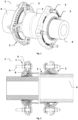
- Figure 1 illustrates an embodiment according to the present disclosure of a pipe coupling and restraining device that comprises: the pipe coupling and restraining device 1, a clamping ring 2, a coupling sleeve 3, the pipe or pipes to be coupled 4, bolts and nuts 5 for joining the sleeve and ring together.
- Figure 2 illustrates in cross-section an embodiment according to the present disclosure of a pipe coupling and restraining device that comprises: the pipe coupling and restraining device 1, clamping ring 2; coupling sleeve 3, bolt 6, nut 7, washer 9, collar assembly 8, pipe 4.
- Figure 3 illustrates in perspective an embodiment according to the present disclosure of a pipe coupling and restraining device that comprises: the pipe coupling and restraining device 1, clamping ring 2; coupling sleeve 3, bolt 6, nut 7, washer 9, collar assembly 8, pipe 4.
- Figure 4 illustrates in detail an embodiment according to the present disclosure of a pipe coupling and restraining device that comprises: clamping ring 2; coupling sleeve 3, bolt 6, nut 7, pipe 4, support body 10, gripper 11, rivet 12 and annular seal 13.
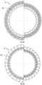
- Figure 5A and 5B illustrate in more detail an embodiment of the collar assembly, seen from two different sides, according to the present disclosure of a pipe coupling and restraining device that comprises collar assembly 8, wedge-shaped segment 15 and annular seal 13 (only present in fig. 5B ).
- Figures 6A and 6B illustrate in more detail an embodiment of the collar assembly according to the present disclosure of a pipe coupling and restraining device that comprises collar assembly 8 and wedge-shaped segment 15.
- Figure 6A and 6B illustrate the adaptability to different diameters by the pipe collar comprising the wedge-shaped segments, as required for different pipe diameters.
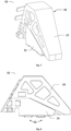
- FIG. 7 illustrates in more detail another embodiment according to the present disclosure of the wedge-shaped segments 15 comprising: the support body 10, an extension surface 17 and the gripper 11.
- FIG 8 illustrates in more detail an embodiment according to the present disclosure of the wedge-shaped segments 15 comprising: the support body 10, the gripper 11 and the rivets 12.
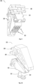
- FIG 9 illustrates in more detail an embodiment according to the present disclosure of the wedge-shaped segments 15 comprising the support body 10, the gripper 11 and rivet 12.
- FIG 10 illustrates in more detail an embodiment according to the present disclosure of the wedge-shaped segments 15 comprising the support body 10, the gripper 11 and rivet 12.
- FIG. 11A pointed rivet 121
- 11B diamond-pattern knurled surface rivet 122
- 11C rivet with a knurled surface with saw-toothed cross-section ridges 123.
- Figures 12 shows two wedge-shaped segments for forming the pipe collar with interdigitated fingers 18 in different interlocking arrangements 12(a) and 12(b) where the diameter of the respective collar assemblies is similar but the respective angle formed between the two segments is dissimilar.
- Figure 13 shows two wedge-shaped segments fully coupled between each other.
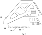
- Figures 14 shows the gripper 11 reacting to the axial movement of the pipe, sliding along the support body 10 and radially into the pipe for enhanced gripping effort.
- Figure 15 shows the support body 10, the gripper 11 and the rivet 12 according to another embodiment.
- Figure 16 shows two wedge-shaped segments coupled between each other.
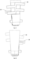
- Figure 17 and 18 represents the frontal view of the wedge-shaped segments and the back view of the wedge-shaped segments, respectively, according to another embodiment showing the interdigitated fingers 18 and snap-fit coupling 19 for coupling to a slot in a adjacent segment while allowing an adjustable gap between adjacent segments.
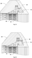
- Figures 19 to 21 show the annular seal 13 before, after and during stretching as the gripper 11 engages further into the pipe.
- Fig. 20 after the stretching there is a deformation of the seal 13.
- the seal becomes stretched with some recesses. It can be seen that the seal becomes thinner in the inferior part as the gripper 11 extends the annular seal 13 along the tube. This improves sealing against the tube. Also, when transporting the pipe coupling and restraining device the annular seal 13 keeps the grippers 11 from falling off the device.
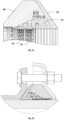
- Figure 22 represents a sectional view of an embodiment according to the present disclosure of a pipe coupling and restraining device mounted sealing and restraining a pipe, according to the disclosure.
Landscapes
- Engineering & Computer Science (AREA)
- General Engineering & Computer Science (AREA)
- Mechanical Engineering (AREA)
- Joints With Sleeves (AREA)
Claims (13)
- Dispositif de raccord et de retenue de tuyau destiné à être raccordé à un tuyau, ledit tuyau définissant un axe longitudinal, comprenant :un manchon de raccord (3) destiné à recevoir une extrémité du tuyau (4) devant être retenu et ayant une première surface de butée annulaire ;une bague de serrage (2) ayant une seconde surface de butée annulaire ;un ensemble pour collier (8) pour retenir et sceller le tuyau, comprenant :
un collier de tuyau formé par des segments en forme de coin (15), chaque segment comprenant un corps de support (10) et un préhenseur (11) arrangé entre le tuyau et le corps de support, et un joint annulaire (13) pour sceller le manchon de raccord au tuyau ;dans lequel le préhenseur (11) est accouplé de manière coulissante au corps de support pour coulisser vers l'avant et radialement vers l'intérieur du tuyau pour retenir le tuyau lorsque le tuyau est retiré du dispositif;dans lequel le corps de support (10) et le préhenseur (11) sont tous deux arrangés pour soutenir le joint annulaire (13) pour le sceller contre la première surface de butée annulaire ;dans lequel le joint annulaire (13) est arrangé pour s'étendre de la première surface de butée annulaire à l'écart entre les préhenseurs (11) et le tuyau (4) ;dans lequel la première ou la seconde surface de butée annulaire est conique telle que lorsque le manchon de raccord (3) et la bague de serrage (2) sont axialement comprimés ensembles, l'ensemble pour collier (8) soit pressé vers l'intérieur du tuyau comprimant le joint radialement entre l'ensemble pour collier (8) et le tuyau (4) et également axialement entre l'ensemble pour collier et la première surface de butée annulaire ;caractérisé en ce quele segment en forme de coin (15) comprend des doigts interdigités (18) sur une face du corps de support (10) destinés à s'engrener avec les doigts interdigités correspondants de deux segments en forme de coin voisins (15) afin de soutenir le joint annulaire en tant que surface circonférentiellement ininterrompue ;dans lequel le préhenseur (11) comprend des extensions pour comprimer radialement le joint annulaire (13) contre le tuyau (4), dans lequel les extensions peuvent être insérées dans les fentes correspondantes sur un préhenseur voisin pour former le collier de tuyau. - Dispositif de raccord et de retenue de tuyau selon la revendication précédente dans lequel la première et la seconde surface de butée annulaire sont toutes deux coniques telles que lorsque le manchon de raccord (3) et la bague de serrage sont axialement comprimés ensembles, l'ensemble pour collier (8) soit pressé vers l'intérieur du tuyau comprimant le joint radialement entre l'ensemble pour collier (8) et le tuyau (4) ainsi que axialement entre l'ensemble pour collier (8) et la première surface de butée annulaire.
- Dispositif de raccord et de retenue de tuyau selon l'une quelconque des revendications précédentes comprenant au moins un, particulièrement deux, plus particulièrement deux, et seulement deux, rivets (12, 121, 122, 123) intégrés dans le préhenseur (11) pour améliorer la prise du tuyau, le rivet ou les rivets (12, 121, 122, 123) étant préférablement moletés en stries droites ou en stries en forme de diamant pour améliorer la prise du tuyau.
- Dispositif de raccord et de retenue de tuyau selon l'une quelconque des revendications précédentes dans lequel le joint annulaire (13) comprend une lèvre annulaire destinée à être fixée au préhenseur (11) et le préhenseur (11) comprend un renfoncement pour recevoir et retenir ladite lèvre annulaire.
- Dispositif de raccord et de retenue de tuyau selon l'une quelconque des revendications précédentes dans lequel le préhenseur (11) comprend des attaches « snap-fit » (19) destinées à raccorder de manière coulissante le préhenseur (11) au corps de support (10) et/ou le préhenseur (11) comprend une face plate vers le tuyau qui a été moletée pour améliorer la prise du tuyau, la face plate du préhenseur (11) étant particulièrement droite moletée avec des stries inclinées contre le retrait du tuyau du dispositif.
- Dispositif de raccord et de retenue de tuyau selon l'une quelconque des revendications précédentes dans lequel le corps de support (10) comprend un rail pour recevoir le préhenseur (11) en un mouvement coulissant et le préhenseur (11) comprend des attaches pour être raccordé de manière coulissante au rail, le rail comprenant préférablement des nervures placées de manière à limiter le mouvement coulissant du préhenseur.
- Dispositif de raccord et de retenue de tuyau selon la revendication 6 dans lequel le rail et le préhenseur (11) sont raccordés de manière coulissante tel que le préhenseur (11) puisse s'incliner autour de l'axe longitudinal du rail pour recevoir une imperfection ou un désalignement de tuyau.
- Dispositif de raccord et de retenue de tuyau selon l'une quelconque des revendications précédentes, dans lequel le préhenseur (11) est arrangé pour étirer le joint annulaire pendant que le préhenseur coulisse sur le tube afin d'augmenter le scellage du dispositif autour du tuyau et/ou le préhenseur (11) est arrangé pour étirer le joint annulaire (13) pendant que le préhenseur coulisse sur le tube détachant le joint annulaire de la première surface de butée pour protéger le joint annulaire en angle entre la première surface de butée et le tuyau.
- Dispositif de raccord et de retenue de tuyau selon l'une quelconque des revendications précédentes, dans lequel le corps de support (10) comprend une extension radiale au milieu du corps et une rainure respective pour recevoir ladite extension du milieu du corps, sur le côté opposé du corps de support, pour guider chaque corps de support (10) avec le suivant, lors de la formation du collier de tuyau.
- Dispositif de raccord et de retenue de tuyau selon l'une quelconque des revendications précédentes, dans lequel le corps de support comprend une attache « snap-fit » et une rainure respective pour recevoir cette attache « snap-fit », sur le côté opposé du corps de support, destinée à être raccordée à un autre corps de support lors de la formation du collier de tuyau.
- Dispositif de raccord et de retenue de tuyau selon l'une quelconque des revendications précédentes, dans lequel le manchon de raccord (3) comprend des onglets de fixation de boulons pour soutenir des boulons ou écrous pour serrer le manchon de raccord et la bague de serrage (2) ensembles, les onglets de fixation de boulons comprenant en particulier des protubérances de blocage pour éviter la rotation du boulon ou écrou, la bague de serrage (2) et le manchon de raccord étant plus préférablement arrangés pour recevoir des écrous et boulons pour attacher la bague de serrage (2) et le manchon de raccord (3) ensembles dans lequel lesdits boulons sont distribués de manière circonférentielle.
- Dispositif de raccord et de retenue de tuyau selon l'une quelconque des revendications précédentes dans lequel la bague de serrage (2) et le manchon de raccord (3) comprennent des onglets perforés arrangés pour recevoir des écrous et boulons de fixation, la bague de serrage comprenant préférablement quatre ou plus d'onglets de fixation de boulons, chaque onglet étant distribué radialement, chacun des onglets étant coplanaire avec l'onglet opposé du manchon, pour recevoir lesdits écrous et boulons.
- Robinet-vanne, clé à douille en T, genou pour clé à douille, ou bride de fixation comprenant le dispositif de raccord et de retenue de l'une quelconque des revendications précédentes.
Applications Claiming Priority (2)
| Application Number | Priority Date | Filing Date | Title |
|---|---|---|---|
| PT11654520 | 2020-06-30 | ||
| PCT/IB2020/056202 WO2022023785A1 (fr) | 2020-06-30 | 2020-09-03 | Raccord de tuyau et dispositif de retenue |
Publications (3)
| Publication Number | Publication Date |
|---|---|
| EP4172525A1 EP4172525A1 (fr) | 2023-05-03 |
| EP4172525C0 EP4172525C0 (fr) | 2025-05-14 |
| EP4172525B1 true EP4172525B1 (fr) | 2025-05-14 |
Family
ID=81603388
Family Applications (2)
| Application Number | Title | Priority Date | Filing Date |
|---|---|---|---|
| EP20751661.8A Active EP4172525B1 (fr) | 2020-06-30 | 2020-09-03 | Dispositif de raccord et de retenue de tuyau |
| EP20829644.2A Withdrawn EP4172526A1 (fr) | 2020-06-30 | 2020-11-30 | Raccord de tuyau et dispositif de retenue |
Family Applications After (1)
| Application Number | Title | Priority Date | Filing Date |
|---|---|---|---|
| EP20829644.2A Withdrawn EP4172526A1 (fr) | 2020-06-30 | 2020-11-30 | Raccord de tuyau et dispositif de retenue |
Country Status (2)
| Country | Link |
|---|---|
| EP (2) | EP4172525B1 (fr) |
| WO (2) | WO2022023785A1 (fr) |
Citations (10)
| Publication number | Priority date | Publication date | Assignee | Title |
|---|---|---|---|---|
| GB2363437A (en) * | 2000-06-13 | 2001-12-19 | Glynwed Pipe Systems Ltd | Pipe coupling device |
| ES1058780U (es) * | 2004-10-28 | 2005-02-01 | Ur-Cast Water Fittings, S.L. | Brida de union autoblocante. |
| WO2007055576A1 (fr) | 2005-11-11 | 2007-05-18 | Georg Fischer Waga N.V. | Dispositif de couplage pour un tube |
| EP2090815A2 (fr) | 2008-01-28 | 2009-08-19 | Fucoli-Somepal Fundição De Ferro, S.A. | Joint multimatériaux avec pinces de blocage |
| WO2010114366A2 (fr) * | 2009-03-30 | 2010-10-07 | Georg Fischer Waga N.V. | Dispositif de couplage |
| GB2474899A (en) * | 2009-10-30 | 2011-05-04 | Crane Ltd T A Viking Johnson | Improved pipe coupling |
| WO2013041491A1 (fr) | 2011-09-19 | 2013-03-28 | E. Hawle Armaturenwerke Gmbh | Dispositif de raccordement tubulaire et procédé de fabrication correspondant |
| WO2014090667A1 (fr) | 2012-12-10 | 2014-06-19 | Georg Fischer Waga N.V. | Dispositif d'accouplement pour un tube |
| WO2016058791A1 (fr) | 2014-10-15 | 2016-04-21 | Vag-Armaturen Gmbh | Dispositif d'assemblage de tuyaux |
| EP3486542A2 (fr) | 2017-11-16 | 2019-05-22 | Georg Fischer WAGA N.V. | Dispositif de raccord |
Family Cites Families (3)
| Publication number | Priority date | Publication date | Assignee | Title |
|---|---|---|---|---|
| US10774964B2 (en) | 2015-08-27 | 2020-09-15 | Robert D. Ryan | Pipe coupling |
| US10533688B2 (en) | 2016-05-16 | 2020-01-14 | Victaulic Company | Coupling having tabbed retainer |
| KR20190021951A (ko) | 2017-08-24 | 2019-03-06 | 현대제철 주식회사 | 파이프 연결 장치 |
-
2020
- 2020-09-03 EP EP20751661.8A patent/EP4172525B1/fr active Active
- 2020-09-03 WO PCT/IB2020/056202 patent/WO2022023785A1/fr not_active Ceased
- 2020-11-30 WO PCT/IB2020/061291 patent/WO2022003413A1/fr not_active Ceased
- 2020-11-30 EP EP20829644.2A patent/EP4172526A1/fr not_active Withdrawn
Patent Citations (12)
| Publication number | Priority date | Publication date | Assignee | Title |
|---|---|---|---|---|
| GB2363437A (en) * | 2000-06-13 | 2001-12-19 | Glynwed Pipe Systems Ltd | Pipe coupling device |
| WO2001096774A1 (fr) | 2000-06-13 | 2001-12-20 | Glynwed Pipe Systems Ltd. | Dispositif servant a accoupler une canalisation |
| ES1058780U (es) * | 2004-10-28 | 2005-02-01 | Ur-Cast Water Fittings, S.L. | Brida de union autoblocante. |
| WO2007055576A1 (fr) | 2005-11-11 | 2007-05-18 | Georg Fischer Waga N.V. | Dispositif de couplage pour un tube |
| EP2090815A2 (fr) | 2008-01-28 | 2009-08-19 | Fucoli-Somepal Fundição De Ferro, S.A. | Joint multimatériaux avec pinces de blocage |
| WO2010114366A2 (fr) * | 2009-03-30 | 2010-10-07 | Georg Fischer Waga N.V. | Dispositif de couplage |
| GB2474899A (en) * | 2009-10-30 | 2011-05-04 | Crane Ltd T A Viking Johnson | Improved pipe coupling |
| US20130082463A1 (en) | 2009-10-30 | 2013-04-04 | Andrew James Benson | Pipe coupling |
| WO2013041491A1 (fr) | 2011-09-19 | 2013-03-28 | E. Hawle Armaturenwerke Gmbh | Dispositif de raccordement tubulaire et procédé de fabrication correspondant |
| WO2014090667A1 (fr) | 2012-12-10 | 2014-06-19 | Georg Fischer Waga N.V. | Dispositif d'accouplement pour un tube |
| WO2016058791A1 (fr) | 2014-10-15 | 2016-04-21 | Vag-Armaturen Gmbh | Dispositif d'assemblage de tuyaux |
| EP3486542A2 (fr) | 2017-11-16 | 2019-05-22 | Georg Fischer WAGA N.V. | Dispositif de raccord |
Non-Patent Citations (9)
| Title |
|---|
| ANONYMOUS: "A big welcome - MULTI/JOINT 3000 Plus DN450 -DN600", GEORG FISCHER WAGA N.V., 1 January 2015 (2015-01-01), XP093370216, Retrieved from the Internet <URL:https://www.ptmg.hr/media/filer_public/81/97/81974fb4-346b-4970-98d0-cf959b09a0eb/multi-joint_3000plus.pdf> |
| ANONYMOUS: "Information Products/Markets No. 51/2015 – BU Utility - Extension MULTI/JOINT 3000 Plus", GEORG FISCHER WAGA N.V., 1 November 2015 (2015-11-01), XP093370221 |
| ANONYMOUS: "Product Catalogue", GEORG FISCHER WAGA N.V., 1 January 2018 (2018-01-01), XP093370214, Retrieved from the Internet <URL:https://www.caldertech.com/Product_Catalogue_Waga_2018.pdf> |
| D10 - INVOICE FROM GEORG FISCHER WAGA N.V. TO INTEREX - WAGA KFT DATED 13 DECEMBER 2019 |
| D13 - EPR DOCUMENTS |
| D14 - Technical drawing 36.01.15 ("Pitbull wedge"), Revision I |
| D15 - Technical drawing 36.02.14 ("Topple D-Range"), Revision B |
| D16 - Technical drawing 36.02.14 ("Topple D-Range"), Revision F |
| D17 - affidavit by Mr. Rudy Woudenberg |
Also Published As
| Publication number | Publication date |
|---|---|
| EP4172525C0 (fr) | 2025-05-14 |
| WO2022003413A1 (fr) | 2022-01-06 |
| EP4172525A1 (fr) | 2023-05-03 |
| WO2022023785A1 (fr) | 2022-02-03 |
| EP4172526A1 (fr) | 2023-05-03 |
Similar Documents
| Publication | Publication Date | Title |
|---|---|---|
| US12129941B2 (en) | Coupling having arcuate stiffness ribs | |
| US12486929B2 (en) | Adapter coupling | |
| EP3022478B1 (fr) | Raccords à nervures de rigidité arquées | |
| EP3561359B1 (fr) | Accouplement à dispositif de retenue à languettes | |
| EP2494249B1 (fr) | Raccord de tube avec dispositif de compression de joint | |
| EP3757437B1 (fr) | Raccord muni d'un dispositif de retenue à languettes et d'orifices d'observation | |
| CN113811712A (zh) | 具有改进密封的凹槽管道联接件 | |
| US20050253382A1 (en) | Mechanical pipe coupling having pipe clearance notches | |
| US11193612B2 (en) | No-hub pipe coupling method and apparatus | |
| EP1164325B1 (fr) | Raccord de tuyaux | |
| WO2022023785A1 (fr) | Raccord de tuyau et dispositif de retenue | |
| EP4127538B1 (fr) | Couplage de retenue de tuyau | |
| EP3702658B1 (fr) | Couplage de tuyaux avec protection contre le cisaillement de pièces de fixation | |
| EP3732387B1 (fr) | Raccord de tuyaux de retenue | |
| HK1218773B (en) | Fittings having arcuate stiffness ribs | |
| HK1212419B (en) | Coupling having arcuate stiffness ribs |
Legal Events
| Date | Code | Title | Description |
|---|---|---|---|
| STAA | Information on the status of an ep patent application or granted ep patent |
Free format text: STATUS: UNKNOWN |
|
| STAA | Information on the status of an ep patent application or granted ep patent |
Free format text: STATUS: THE INTERNATIONAL PUBLICATION HAS BEEN MADE |
|
| PUAI | Public reference made under article 153(3) epc to a published international application that has entered the european phase |
Free format text: ORIGINAL CODE: 0009012 |
|
| STAA | Information on the status of an ep patent application or granted ep patent |
Free format text: STATUS: REQUEST FOR EXAMINATION WAS MADE |
|
| 17P | Request for examination filed |
Effective date: 20230130 |
|
| AK | Designated contracting states |
Kind code of ref document: A1 Designated state(s): AL AT BE BG CH CY CZ DE DK EE ES FI FR GB GR HR HU IE IS IT LI LT LU LV MC MK MT NL NO PL PT RO RS SE SI SK SM TR |
|
| DAV | Request for validation of the european patent (deleted) | ||
| DAX | Request for extension of the european patent (deleted) | ||
| GRAP | Despatch of communication of intention to grant a patent |
Free format text: ORIGINAL CODE: EPIDOSNIGR1 |
|
| STAA | Information on the status of an ep patent application or granted ep patent |
Free format text: STATUS: GRANT OF PATENT IS INTENDED |
|
| INTG | Intention to grant announced |
Effective date: 20241205 |
|
| GRAS | Grant fee paid |
Free format text: ORIGINAL CODE: EPIDOSNIGR3 |
|
| GRAA | (expected) grant |
Free format text: ORIGINAL CODE: 0009210 |
|
| STAA | Information on the status of an ep patent application or granted ep patent |
Free format text: STATUS: THE PATENT HAS BEEN GRANTED |
|
| AK | Designated contracting states |
Kind code of ref document: B1 Designated state(s): AL AT BE BG CH CY CZ DE DK EE ES FI FR GB GR HR HU IE IS IT LI LT LU LV MC MK MT NL NO PL PT RO RS SE SI SK SM TR |
|
| REG | Reference to a national code |
Ref country code: GB Ref legal event code: FG4D |
|
| REG | Reference to a national code |
Ref country code: CH Ref legal event code: EP |
|
| REG | Reference to a national code |
Ref country code: IE Ref legal event code: FG4D |
|
| REG | Reference to a national code |
Ref country code: DE Ref legal event code: R096 Ref document number: 602020051284 Country of ref document: DE |
|
| U01 | Request for unitary effect filed |
Effective date: 20250612 |
|
| U07 | Unitary effect registered |
Designated state(s): AT BE BG DE DK EE FI FR IT LT LU LV MT NL PT RO SE SI Effective date: 20250623 |
|
| REG | Reference to a national code |
Ref country code: ES Ref legal event code: FG2A Ref document number: 3034867 Country of ref document: ES Kind code of ref document: T3 Effective date: 20250825 |
|
| U20 | Renewal fee for the european patent with unitary effect paid |
Year of fee payment: 6 Effective date: 20250819 |
|
| REG | Reference to a national code |
Ref country code: CH Ref legal event code: U11 Free format text: ST27 STATUS EVENT CODE: U-0-0-U10-U11 (AS PROVIDED BY THE NATIONAL OFFICE) Effective date: 20251001 |
|
| PG25 | Lapsed in a contracting state [announced via postgrant information from national office to epo] |
Ref country code: GR Free format text: LAPSE BECAUSE OF FAILURE TO SUBMIT A TRANSLATION OF THE DESCRIPTION OR TO PAY THE FEE WITHIN THE PRESCRIBED TIME-LIMIT Effective date: 20250815 |
|
| PGFP | Annual fee paid to national office [announced via postgrant information from national office to epo] |
Ref country code: NO Payment date: 20250725 Year of fee payment: 6 |
|
| PGFP | Annual fee paid to national office [announced via postgrant information from national office to epo] |
Ref country code: GB Payment date: 20250923 Year of fee payment: 6 |
|
| PG25 | Lapsed in a contracting state [announced via postgrant information from national office to epo] |
Ref country code: HR Free format text: LAPSE BECAUSE OF FAILURE TO SUBMIT A TRANSLATION OF THE DESCRIPTION OR TO PAY THE FEE WITHIN THE PRESCRIBED TIME-LIMIT Effective date: 20250514 |
|
| PG25 | Lapsed in a contracting state [announced via postgrant information from national office to epo] |
Ref country code: RS Free format text: LAPSE BECAUSE OF FAILURE TO SUBMIT A TRANSLATION OF THE DESCRIPTION OR TO PAY THE FEE WITHIN THE PRESCRIBED TIME-LIMIT Effective date: 20250814 |
|
| PGFP | Annual fee paid to national office [announced via postgrant information from national office to epo] |
Ref country code: IE Payment date: 20250917 Year of fee payment: 6 |
|
| PG25 | Lapsed in a contracting state [announced via postgrant information from national office to epo] |
Ref country code: IS Free format text: LAPSE BECAUSE OF FAILURE TO SUBMIT A TRANSLATION OF THE DESCRIPTION OR TO PAY THE FEE WITHIN THE PRESCRIBED TIME-LIMIT Effective date: 20250914 |
|
| PG25 | Lapsed in a contracting state [announced via postgrant information from national office to epo] |
Ref country code: SM Free format text: LAPSE BECAUSE OF FAILURE TO SUBMIT A TRANSLATION OF THE DESCRIPTION OR TO PAY THE FEE WITHIN THE PRESCRIBED TIME-LIMIT Effective date: 20250514 |
|
| PGFP | Annual fee paid to national office [announced via postgrant information from national office to epo] |
Ref country code: CH Payment date: 20251001 Year of fee payment: 6 |
|
| PG25 | Lapsed in a contracting state [announced via postgrant information from national office to epo] |
Ref country code: CZ Free format text: LAPSE BECAUSE OF FAILURE TO SUBMIT A TRANSLATION OF THE DESCRIPTION OR TO PAY THE FEE WITHIN THE PRESCRIBED TIME-LIMIT Effective date: 20250514 |
|
| PGFP | Annual fee paid to national office [announced via postgrant information from national office to epo] |
Ref country code: PL Payment date: 20250812 Year of fee payment: 6 |
|
| PG25 | Lapsed in a contracting state [announced via postgrant information from national office to epo] |
Ref country code: SK Free format text: LAPSE BECAUSE OF FAILURE TO SUBMIT A TRANSLATION OF THE DESCRIPTION OR TO PAY THE FEE WITHIN THE PRESCRIBED TIME-LIMIT Effective date: 20250514 |
|
| PGFP | Annual fee paid to national office [announced via postgrant information from national office to epo] |
Ref country code: ES Payment date: 20251008 Year of fee payment: 6 |
|
| PLBI | Opposition filed |
Free format text: ORIGINAL CODE: 0009260 |
|
| REG | Reference to a national code |
Ref country code: CH Ref legal event code: L10 Free format text: ST27 STATUS EVENT CODE: U-0-0-L10-L00 (AS PROVIDED BY THE NATIONAL OFFICE) Effective date: 20260225 |
|
| PLAX | Notice of opposition and request to file observation + time limit sent |
Free format text: ORIGINAL CODE: EPIDOSNOBS2 |
|
| 26 | Opposition filed |
Opponent name: GEORG FISCHER WAGA N.V. Effective date: 20260213 |
|
| PG25 | Lapsed in a contracting state [announced via postgrant information from national office to epo] |
Ref country code: MC Free format text: LAPSE BECAUSE OF FAILURE TO SUBMIT A TRANSLATION OF THE DESCRIPTION OR TO PAY THE FEE WITHIN THE PRESCRIBED TIME-LIMIT Effective date: 20250514 |
|
| PLBB | Reply of patent proprietor to notice(s) of opposition received |
Free format text: ORIGINAL CODE: EPIDOSNOBS3 |