EP4172571B1 - Gehäuse für ein rotierendes bauteil - Google Patents
Gehäuse für ein rotierendes bauteil Download PDFInfo
- Publication number
- EP4172571B1 EP4172571B1 EP21743061.0A EP21743061A EP4172571B1 EP 4172571 B1 EP4172571 B1 EP 4172571B1 EP 21743061 A EP21743061 A EP 21743061A EP 4172571 B1 EP4172571 B1 EP 4172571B1
- Authority
- EP
- European Patent Office
- Prior art keywords
- housing
- segment
- antenna
- electronics
- housing segment
- Prior art date
- Legal status (The legal status is an assumption and is not a legal conclusion. Google has not performed a legal analysis and makes no representation as to the accuracy of the status listed.)
- Active
Links
Images


Classifications
-
- G—PHYSICS
- G01—MEASURING; TESTING
- G01D—MEASURING NOT SPECIALLY ADAPTED FOR A SPECIFIC VARIABLE; ARRANGEMENTS FOR MEASURING TWO OR MORE VARIABLES NOT COVERED IN A SINGLE OTHER SUBCLASS; TARIFF METERING APPARATUS; MEASURING OR TESTING NOT OTHERWISE PROVIDED FOR
- G01D11/00—Component parts of measuring arrangements not specially adapted for a specific variable
- G01D11/24—Housings ; Casings for instruments
- G01D11/245—Housings for sensors
-
- G—PHYSICS
- G01—MEASURING; TESTING
- G01L—MEASURING FORCE, STRESS, TORQUE, WORK, MECHANICAL POWER, MECHANICAL EFFICIENCY, OR FLUID PRESSURE
- G01L3/00—Measuring torque, work, mechanical power, or mechanical efficiency, in general
- G01L3/02—Rotary-transmission dynamometers
- G01L3/04—Rotary-transmission dynamometers wherein the torque-transmitting element comprises a torsionally-flexible shaft
- G01L3/10—Rotary-transmission dynamometers wherein the torque-transmitting element comprises a torsionally-flexible shaft involving electric or magnetic means for indicating
- G01L3/108—Rotary-transmission dynamometers wherein the torque-transmitting element comprises a torsionally-flexible shaft involving electric or magnetic means for indicating involving resistance strain gauges
Definitions
- the invention relates to a housing segment for providing a housing for a component rotating about a rotation axis, wherein the housing segment is provided for covering a partial area in the axial direction of the rotation axis and for covering a partial area in the circumferential direction of the rotating component, as well as a housing comprising at least one housing segment.
- a measuring device for detecting loads, in particular torque, bending moment and axial force on rotating components such as shafts, spindles or journals, is known.
- the measuring device measures the change in length that occurs under load using at least one strain gauge attached to the component and records it without contact.
- Rotor electronics are provided for contactless feeding of the supply energy for the strain gauge and for the contactless transmission of the measured values to an evaluation unit.
- the rotor electronics are arranged in one or more protective rings that surround the strain gauge.
- EP2078962A1 shows a housing segment for accommodating electronics, comprising a cable feedthrough.
- a simple assembly of the electronics in the housing segment is advantageously shown.
- the protective ring(s) are arranged on the component with support on one side or are designed to be flexible in relation to the component.
- the protective ring is designed with sealing ribs arranged on both sides of the strain gauge.
- the protective ring is designed asymmetrically, with the sealing rib on one side creating a frictional connection and thus a secure connection to the component.
- the sealing rib on the other side has a narrow contact surface and is thus supported against the component. Due to the narrow contact surface, however, almost no load can be transferred from the rotating component.
- System 1 uses an antenna that rotates with the universal joint shaft.
- a fixed receiver is used to transmit the signal.
- the signal provides a torque measurement value.
- System 2 uses a stationary ring antenna.
- a transmitter/receiver unit that rotates with the universal joint shaft sends the signals to the stationary ring antenna.
- the disadvantage is that, depending on the ring diameter, the conventional manufacturing process can lead to tensions within the ring material, which can then lead to the ring ends expanding or contracting when the ring is split during production.
- a second person is required to help mount the ring on the shaft until the second ring half is put on and the screw connections are closed.
- the volume of the ring is determined by an internal electronics pocket and disassembly is also necessary for repairs to the electronics. is required.
- the weight of the ring determines the centrifugal force. The weight has also proven to be a disadvantage during assembly.
- the ring halves are often glued to the rotating component, which means that the component can only be reused to a limited extent after it has been dismantled and the adhesive has been cleaned off.
- the invention is based on the object of providing an improved housing.
- the following aspects were considered in particular:
- the housing allows for simplified installation.
- the invention is based on the object of simplifying a method for producing/providing a housing.
- the invention was based on the object of providing a housing that facilitates maintenance and repair or reduces the associated effort.
- the housing includes a housing segment, wherein the housing segment is made of a plastic, comprises an electronics housing for an electronics module, has a cavity arranged radially outside the electronics housing and connected to the electronics housing via an opening for receiving an antenna.
- a housing segment made of plastic is advantageous because it is lighter than the metal materials used in the state of the art. This reduces centrifugal forces and vibrations.
- a compact design also enables cost-effective production and simplified assembly.
- a plastic housing can protect the antenna from environmental influences without reducing its functionality through shielding from the housing.
- a connection between the antenna and the electronics housing A connecting cable must be provided between the electronics and the antenna.
- Plastics in the sense of this invention are carbon-containing polymers which are largely free of metals or other materials that shield electromagnetic waves, at least in the area of the cavity for accommodating the antenna.
- the housing is also advantageously characterized by the fact that the housing is composed of interconnected housing segments.
- At least one housing segment has a housing for electronics, in particular for accommodating a prefabricated electronic module.
- This at least one housing segment can be manufactured using 3D printing, also known as additive manufacturing.
- Additive manufacturing is also often abbreviated to AM.
- Additive manufacturing can provide individual adaptation to a surface contour of the outer surface of a rotating component.
- 3D printing makes it possible to manufacture the housing segment decentrally, which simplifies and speeds up delivery.
- manufacturing from a plastic such as PA12 or PA6 has proven to be advantageous as a cost-effective material.
- Such plastic materials are already available today as standard printing materials for 3D printing.
- the required lead time can be kept low for small quantities. For example, no molds or NC programming are required on site. Long transport routes can also be avoided.
- the housing segments can be connected to one another to form a circumferential housing.
- the housing preferably surrounds the rotating component coaxially to the axis of rotation.
- the housing segments are connected to one another in a form-fitting manner.
- This can be done, for example, by means of a
- This can be done by means of a snap-in connection.
- Such snap-in connections can be provided inexpensively. It has proven to be advantageous to provide a connection with play. This can compensate for manufacturing tolerances or deviations from predetermined or specified nominal dimensions. Assembly is particularly easy. This means that assembly can also be carried out by one employee alone.
- the housing can be connected to the rotating component in a force-fitting manner, preferably by means of a clamping device.
- the force-fitting connection ensures that the housing rests firmly on the component, and the housing can be released again by releasing the force-fitting connection. This means that gluing may not be necessary.
- a simple dismantling option makes it easier to repair the components protected by the housing, and individual segments of the housing itself can also be replaced more easily. This is particularly easy if the segments are designed to be detachable from one another.
- a clearance in the circumferential direction when locking there is provision for a clearance in the circumferential direction when locking.
- This has an advantageous effect on assembly, since pre-assembly can be carried out first and the housing surrounds the rotating component as a ring-shaped housing.
- a particularly simple design provides at least one elongated hole in the circumferential direction. This allows clearance to be provided in the circumferential direction when locking into the elongated hole.
- At least one housing segment is provided with an electronics housing in the form of a hollow space.
- This hollow space can be used to accommodate electronics. It can also be provided to accommodate the electronics as a pre-assembled electronics module.
- this electronics housing is accessible from the outside of the housing, i.e. from the axial direction, without removing housing segments. It has proven advantageous to provide a central web that protrudes in the radial direction and is accessible from the axial direction, so that when the electronics housing is formed in this central web, easy accessibility of the electronics housing is guaranteed. It may happen that the electronics have to be replaced or that components of an electronics system have to be replaced. In particular, it may be necessary to carry out maintenance on a regular basis. In these cases, it is particularly advantageous if the housing is easily accessible. For example, the housing can only be closed with a removable and reinstallable cover. Alternatively, the electronics module can already contain the function of the cover.
- the housing is formed by housing segments manufactured as identical parts. This reduces the number of parts, which is advantageous. A break-out side wall can then only be broken out of the housing segment where the electronics housing is required. The break-out side walls can remain in the other housing segments, thus preventing noise during operation and the accumulation of dirt in the electronics housings provided.
- At least one housing segment with an electronics housing is produced using 3D printing.
- base segments without an electronics housing can be provided.
- the base segments preferably have a shorter extension in the circumferential direction and can also be produced as a mass component using another manufacturing process. Adaptation to the place of use can be carried out using the at least one housing segment. This means that the number of individual components can be reduced.
- the production time can also be reduced because only the housing segment is produced using 3D printing. With 3D printing, the production speed is currently still very limited. Furthermore, a cost advantage can be achieved if a mass production process is used for the Base segments are used and thus, due to high quantities, a cheaper manufacturing process per unit, such as injection molding, is used.
- clamping device for a force-fitting connection between the housing and the rotating component, the clamping device having at least one clamping band, preferably two clamping bands.
- Two clamping bands allow the force-fitting connection for the narrow web and the wide web to be dosed separately.
- Such clamping bands are available as standard components and are therefore inexpensive.
- Clamping bands are also easy to assemble and disassemble. Each clamping band can be accommodated in a circumferential groove so that slipping in the axial direction is prevented. The groove also contributes to easy assembly.
- the clamping band By using the clamping band, an even pressure distribution can be achieved on the ring-shaped housing and thus on the housing segment. Peak stresses in individual areas can thus be avoided. This results in lower requirements in terms of strength for the polymer material used.
- the housing is provided with a shield on its inside.
- the shield can be held by holding elements distributed around the circumference. It has proven particularly advantageous that the shield can be pushed in.
- the shielding ensures that the magnetic field lines emanating from the stationary receiver are advantageously guided around the antenna. This reduces the magnetic field losses caused by the wave.
- the housing segment has a receptacle, preferably continuous in the circumferential direction, for an antenna radially on the outside.
- a groove is provided as the receptacle, which is formed on the outermost radius of the central web. This allows the connection to the antenna and also the connection to the sensors arranged in the housing to be kept short.
- the radial distance between shaft and antenna is in the range of 40 mm and 80 mm, preferably greater than 60 mm.
- the housing segment has a narrow web and a wide web.
- the webs are intended for a lateral closure of the housing.
- the wide web has a larger axial extension and thus a contact area with the rotating component than the narrow web.
- the wide web is designed with cavities for a lightweight structure, preferably with a honeycomb structure.
- the lightweight structure also achieves a high load-bearing capacity.
- the lightweight structure makes it possible to minimize both the resulting weight and the required material. For 3D printing, it is also advantageous to have an even material distribution. Large jumps from one layer to the next should be avoided due to stress and distortion.
- the electronics are pre-assembled as an electronic module.
- the pre-assembled electronic module can then be installed quickly. Replacement is also possible quickly. This means that downtimes can be minimized. It is also advantageous if the housing is easily accessible. The manufacturer can also carry out a preliminary check of such an electronic module, so that possible errors and malfunctions are also minimized.
- electromagnetic shielding can be provided directly in the housing. This means that the shielding can be integrated into the manufacturing process.
- a suitable geometry on the inner ring side means that any required shielding tape can be mounted and fixed without tools. This means that a conventional adhesive connection can be dispensed with.
- a further advantage is a housing in which a shield against electromagnetic radiation is arranged, suitable for shielding the internal cavity and/or the electronics housing against electromagnetic waves.
- the shielding can be made from a metallic mesh, an electrically conductive sheet or another fabric that shields electromagnetic waves.
- the shielding can also be arranged in such a way that it shields not only the electronics but also the sensors on the shaft.
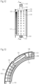
- FIG 1 is a section of a universal joint shaft 3 as an example of a rotating component 1.
- the universal joint shaft 3, hereinafter also referred to as shaft, is provided with sensors 301 on the outer diameter, not shown here. Two sensors are provided, which are mounted opposite one another or offset by 180°.
- the sensor 301 rotates with the shaft 3 and is covered and protected by the housing 7.
- One embodiment of a sensor 301 is shown in Figure 2 and is described in detail below.
- the shaft 3 rotates about the axis of rotation 51.
- the axial direction of the shaft is marked with 53.
- the radial direction is marked with 55 and the circumferential direction is marked with 57.
- the shaft 3 is coaxially surrounded by a housing 7.
- the housing 7 rests on the outer surface 4 of the shaft 3.
- the housing 7 has four housing segments 10.
- the housing segments 10 are each connected to adjacent housing segments 10 by a positive connection 21.
- a clamping device 25 is provided to provide a force-locking connection 26 with the shaft 3.
- This clamping device 25 here comprises two clamping bands 27 with a closure 29.
- the clamping bands 27 are arranged on both sides of a central web 45 and the strength of the force-locking connection to the shaft 3 can be adjusted in each case by means of the clamping closure 29.
- the central web 45 projects in the radial direction 55 beyond the areas with the clamping bands 27.
- Housings 61 for an electronic module are formed in the central web of each housing segment 10.
- the housing segments 10 are identical parts, whereby only one of the housings 61 is required to accommodate an electronic module 171.
- the electronic module can be a pre-assembled and encapsulated electronics.
- An antenna 41 is arranged on the radial outer circumference of the central web 45.
- the antenna 41 enables transmission and reception.
- the power supply is provided via the transmission signal and measurement signals are received in parallel.
- a stationary transmitter/receiver unit 81 is assigned to the antenna 41.
- the transmitter/receiver unit also referred to as a stationary receiver, is attached to a part of the stationary bearing housing 91 by an adjusting bracket 93.
- the adjustment bracket has a radial adjustment connection 97 and an axial adjustment connection 95.
- the adjustment connections 95, 97 include elongated holes and screws so that the position of the adjustment bracket 93 can be adjusted in the radial direction 55 and axial direction 53.
- the stationary receiver 81 is firmly connected to the stationary adjustment bracket 93, here via a spacer 85.
- the spacer 85 enables better ventilation of the stationary transmitter unit 81 through a ventilation slot 87.
- the spacer 85 made of plastic and the defined distance from the adjustment bracket 93 keep the losses of the inductive energy transmission low.
- the stationary transmitting unit 81 makes it possible to receive signals and data from the rotating antenna 41 and also to transmit energy to the rotating antenna 41 and thus to the electronic module 171.
- an adjustment gauge 89 can be used, as shown in Figure 10 shown in detail. Adjustment after mounting the housing 7.
- a torque measuring device 9 is provided by strain gauges with associated electronics and a transmitting and receiving unit.
- the housing 7 can also be used to protect other components arranged on a rotating component. In particular, other sensors can also be accommodated in the housing.
- FIG 2 is a detailed excerpt from Figure 1
- Sensors 301 are arranged inside the housing 7.
- the torque sensor system 310 shown here comprises two measuring points, which are arranged at an angle of 180°.
- the arrangement of the strain gauges offset by 180° on the circumference minimizes the influence of any bending forces that may occur on the torque signal.
- Each measuring point comprises a first strain gauge package 320 and a second strain gauge package 330.
- the two measuring points are each connected to a support point 340.
- the first and second strain gauge packages of the two measuring points can be used to detect, for example, torsion or other forces acting on the shaft 3 or a rotating component.
- the support point 340 is electrically connected via a line 350 to a not further shown in the Housing 61 is connected to the electronic module 171.
- the signals can be transmitted to a stationary transmitting/receiving unit 81 via the antenna 41.
- the transmitting/receiving unit is firmly connected to the adjustment bracket 93, whereby the adjustment bracket 93 offers the possibility of adjustment in the axial 53 and radial direction 55.
- the sensors are sketched in front of the housing, but in reality the sensors 301 are arranged between the webs 105, 107 and between the ceiling of the housing interior 112 and the surface of the rotating component.
- the housing is made of Figure 1 shown in detail.
- the housing 7 consists of four housing segments 100. A different number of housing segments 100 could also be provided. These housing segments 100 were manufactured in a 3D printing process as plastic segments 103. This makes it possible to individually adapt the housing segments 100 and in particular their radius of curvature in the circumferential direction 57 to the diameter of the intended installation location.
- the housing segments 100 are designed as identical parts.
- In each housing segment 100 there is a housing 161 for an electronic module 171, as in Figure 9 shown.
- the housings 161 are initially closed by break-out side walls 163. If the housings 161 were open, noise would be generated through the openings during operation and dirt would collect in the unused housings and openings.
- the side walls 163 of the housing 161 can be easily broken out, e.g. using a screwdriver.
- a closing lid 185 is used to close the housing 161. This closing lid allows the housing 161 to be resealed. If the electronics or the electronics module 171 is defective, the closing lid 185 can be removed for replacement and after replacing the electronics module 171 or the defective components, the housing 161 can be closed again.
- the housing 161 is accessible from the axial direction 53; dismantling the housing 7 or individual housing segments 100 is not necessary.
- the housing segments 100 are connected by positive connections 21 to the adjacent housing segments 100 to form a circumferential Housing 7 are connected to each other.
- This connection mechanism with the locking connection 130 between the housing segments provides pre-fixing during assembly. This enables assembly by one employee without additional tools.
- Fig.4 the intended locking connection is described.
- Locking lugs 133 are formed on an end of the housing segment 100 provided in the circumferential direction 57. These locking lugs 133 are arranged on both sides of the segment of the center web 145. These locking lugs 133 each engage in an elongated hole 131 of the adjacent housing segment 100. Through the elongated hole 131, Fig.5 , a connection with play 135 is made possible.
- the housing segment thus has locking lugs in the circumferential direction at one end and elongated holes 131 assigned to the locking lugs 133 at the other end.
- the play makes assembly easier and even minor deviations in the circumference of the rotating component 1 can be compensated.
- a centering 151 with a centering bolt 153, Fig.5 , and a centering recess 155, Fig.4 is provided.
- two locking connections and one centering are provided for each connection point, but several centering connections and only one locking connection 130 or several locking connections could also be provided.
- the centering 151 and the locking connection 130 help to facilitate and stably connect the housing segments.
- the housing 7 encloses the rotation axis 51.
- a force-locking connection 26 is provided for a firm connection to the rotating component.
- the housing segment 100 has a groove on both sides of the center web 145 for receiving a tensioning band, not shown.
- the groove 127 prevents the tensioning band from slipping in the axial direction.
- an antenna groove 143 for mounting the antenna 41 is formed on the center web 145.
- the antenna groove prevents the antenna from slipping in the axial direction.
- the housing outer side 113 of the housing segment 100 is in the antenna groove 143 with antenna attachments 141, see also Figure 7 ,
- the antenna mounts 141 are provided with cable bushings 167, Fig.6
- the cable feedthroughs extend from the outside of the housing 113 of the housing segment into the housing 161.
- a breakthrough 165 is provided to an inside of the housing 111 of the housing segment 100. This serves to accommodate an electrical connection 177 to the sensor system 310. Further openings are visible on the inside of the housing 111. These openings are discharge openings 123 for excess, unfused material.
- the housing segments are designed with hollow spaces to reduce weight and the amount of material required.
- the housing segment 100 is designed with a wide web 107 and a narrow web 105 as an axial side wall. The webs 105, 107 are force-fitted to the rotating component. The different sized contact surfaces reduce the stress on the housing segment, since the force fit is of different strengths due to the different size of the contact surface formed.
- the wide web 107 is designed in lightweight construction 117.
- a honeycomb structure is provided here as the lightweight structure 109.
- tongues 121 are formed as a holding element 119 for a shield 115.
- the tongues 121 are slightly curved radially inwards at the ends. This makes it easier to insert a shield 115 and also increases the stability of the tongues.
- the volume of the housing extends in the axial direction 53 between the webs 105 and 107 and is marked with 147.
- the height and thus the radial extension of the housing interior volume are marked with 149.
- the electronics can be pre-assembled as an electronic module before final assembly. In the event of a defect, the entire electronic module 171 can also be replaced. To do this, an electrical connection 177 to the sensor system is then removed, including a strain relief 181 provided. Antenna connections 175 must be removed and a fastening 183 of the electronic module 171 to a fastening element 169 formed in the housing 161 must be removed so that the electronic module can be removed in its entirety from the housing 161.
- the electronic module comprises a circuit board 179 which carries electronic components, wherein the electronic components may be encapsulated with the circuit board.
- the electronics are detachably encapsulated in the housing. This means that individual circuit boards can still be replaced.
- the functionality of the prefabricated circuit board and the electronic module 171 can be checked before final assembly. If a suitable material is selected (e.g. plastic filled with metal particles), electromagnetic shielding can be provided directly in the housing.
- a spacer 85 is shown, whereby the spacer allows good ventilation of the transmitting/receiving unit 81.
- Figure 10 is the one based on Figure 1
- the previously mentioned setting gauge 89 is shown in detail. This allows predetermined distances between the antenna and the transmitting/receiving unit 81 to be set.
- a support 86 can be inserted in the desired position.
- the ring-shaped housing 7 can be fixed using a commercially available clamping band 27. This ensures even pressure distribution on the housing 7 and avoids peak stresses in individual areas. This results in lower demands on the strength of the polymer material used. For example, when used as a housing on a universal joint shaft at a speed of 0 to 3000 rpm and a diameter of 100 mm to 2200 mm and a strength or yield stress in the range of 65 MPa to 80 MPa is sufficient.
- fixation specifically the clamping device 25 is also subjected to less stress, since the housing 7 with the individual housing segments 10 is designed to be weight-optimized.
- a shielding tape can be mounted and fixed without tools using the retaining elements 119 on the inside of the housing. This means that a conventional adhesive connection can be dispensed with. This means that both the installation itself and the replacement are easy to install.
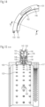
- FIG. 8 Another variant of segmented housing is in Figure 8 shown.
- many base segments 210 which are not adapted to the respective universal joint diameter, are joined together to form a chain.
- a locking connection with a spring locking lug 133 is shown.
- the spring locking lug engages in an elongated hole, so that a positive connection with play is provided.
- There is only housing segment 100 comprising a housing 161.
- This housing segment 100 serves as a type of "chain lock" or locking element of the housing 7.
- the advantage here is the greater flexibility compared to varying universal joint diameters, since the base segment 210 is independent of the diameter. Only one housing segment 100 is required, individually adapted to the specific application, e.g. the diameter of the installation location.
- the base elements are adapted in their outer contour to the housing segment 100.
- the base segment also has a central web 245 for receiving the antenna 41.
- the contact surfaces to the rotating component can also be designed in a similar way to the contact surface of the narrow web 105 and the wide web 107.
- housing segment 100 together with base segments 210 to form a housing 7.
- housing 7 is shown arranged on a hollow shaft 5.
- contour of the inside of the housing is not visible in this illustration.
- FIG. 12 to 15 an alternative design of the housing segment 100 in lightweight construction is shown.
- a lightweight design of the housing segment is particularly tailored to production using additive processes.
- the housing segment has a central web, whereby this central web has a larger radial extent.
- the rectangular shape has the advantage that coordination or adaptation to the curvature of the housing segment 100 is not necessary.
- Centering webs are formed in the area of the webs 107 and 107 for centering 151.
- These centering webs 154 engage in centering recesses 155 formed in opposite directions.
- the locking elements 133 and the elongated holes 131 are provided radially below the antenna groove 143. As a result, the locking connection is protected from damage by means of the elongated hole 131 and locking lug 133 due to its internal arrangement.
- FIG. 15 is a section through the housing segment along BB from Figure 14 with the viewing direction shown.
- the center web has side housing walls 146.
- the antenna groove 143 is formed in the circumferential direction between the side walls 146.
- a cavity 150 is formed in the center web.
- a support structure 191 is provided within the cavity 150.
- This support structure has support struts 195 to the bottom of the antenna groove.
- Support struts 197 are formed to the side walls 146 and support struts 199 are formed to the ceiling of the housing interior 112. These support struts are formed by support struts 193 formed in the circumferential direction, Fig. 13 connected to each other. Openings 123 are formed in the cover 112 of the housing interior through which excess material can be removed.
- FIG 16 the production chain for additive manufacturing, also known as 3D printing, is shown.
- the data for 3D printing representing the component to be additively manufactured can be fed to the control unit via a data carrier 426 or can also be fed to the control unit via a network connection.
- the data can be contained in a computer program or the computer program for processing the data can already be present in the control unit.
- the control unit controls the 3D printer to produce the 3D printed component, such as in particular the housing segment 100.
- the base segments 210 can also be produced using 3D printing, which enables on-site production.
- the spacer 85 and the setting gauge can also be produced using 3D production.
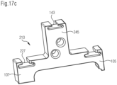
- FIG. 17a to 17c A variant with basic segments is shown.
- the base segments are not connected to one another by means of locking lugs, but have radially partially closed grooves 227 for receiving the clamping band 237.
- a clamping band with through holes 237 has been used.
- Such clamping bands 237 can be clamped particularly well.
- Each base segment 210 has two contact surfaces 247 tilted towards one another on the webs 107 and 105. The tilted arrangement of the contact surfaces 247 relative to one another ensures that both the narrow side web 105 with two contact points and the wide side web 107 with two contact points rest on the rotating component 1 in the clamped state.
- the base segments 210 are provided with two offset holes.
- the base segments can be pre-mounted on rods and the tensioning straps and the antenna can be inserted into the grooves 227, 143 provided for this purpose.
- These base segments 210 can be manufactured using injection molding, 3D printing and machining.
- Rotating component Cardan shaft, 4 Outer surface of cardan shaft 5 Hollow shaft 7 Housing 9 Torque measuring device 10 Housing segment 21 Positive-locking connection 25 Clamping device 26 Force-locking connection 27 Tension strap 29 Closure strap 41 antenna 45 Center bridge 51 Rotation axis 53 Axial direction 55 Radial direction 57 Circumferential direction 61 Electronics housing 81 stationary receiver, transmitting-receiving unit 85 Spacer 86 Edition 87 Ventilation slot 89 Adjustment gauge - distance between antenna and fixed receiver 91 Part of the stationary bearing housing 93 Adjustment bracket 95 Axial adjustment connection 97 Radial adjustment connection 100 Housing segment in lightweight construction 103 Plastic segment 105 Side bar narrow 107 Side bar wide 109 Lightweight structure 111 Housing interior 112 Ceiling inside housing 113 Housing exterior 115 shielding 117 Side bar in lightweight construction (honeycomb structure) 119 Holding elements 121 Tongues 123 Openings for excess material 127 Groove clamping band 130 Snap connection 131 Long hole 133 locking lug 135 Game 141 Antenna mounting 143 An
Landscapes
- Physics & Mathematics (AREA)
- General Physics & Mathematics (AREA)
- Casings For Electric Apparatus (AREA)
- Arrangements For Transmission Of Measured Signals (AREA)
- Details Of Aerials (AREA)
Description
- Die Erfindung betrifft ein Gehäusesegment für die Bereitstellung eines Gehäuses für ein um eine Rotationsachse rotierenden Bauteils, wobei das Gehäusesegment für eine Abdeckung eines Teilbereiches in axialer Richtung der Rotationsachse und für eine Abdeckung eines Teilbereiches in Umfangsrichtung des rotierenden Bauteiles vorgesehen ist, sowie ein Gehäuse umfassend zumindest ein Gehäusesegment.
- Aus der
DE 198 57 770 ist eine Drehmomentmessvorrichtung an rotierenden Bauteilen, wie Wellen oder Zapfen, bekannt. Durch die bei einer Rotation wirkenden Kräfte ergeben sich infolge der elastischen Verformung des Bauteils Längenänderungen. Durch auf dem Bauteil befestigten Dehnungsmessstreifen wird mit Hilfe dieser eine proportionale Widerstandsänderung gemessen und berührungslos erfasst. Für eine berührungslose Einspeisung der Versorgungsenergie für die Dehnungsmessstreifen sowie für eine ebenfalls berührungslose Rückübertragung der Messwerte an eine Auswerteeinheit, ist eine Rotorelektronik vorgesehen. Die Rotorelektronik ist in einem die Dehnungsmessstreifen umgreifenden Kunststoffring angeordnet. Dabei sind die Dehnungsmessstreifen zu ihrem Schutz von einem formstabilen gegen das rotierende Bauteil beidseitig der Dehnungsmessstreifen abdichtenden Metallschutzring umgeben. Der Metallschutzring trägt seinerseits koaxial auf seinem Umfang den Kunststoffring, wobei die Rotorelektronik von dem der Kunststoffring aufgenommen ist. Nachteilig ist, dass dieser Schutzring eine zusätzliche Versteifung des Bauteils verursacht und damit die Messergebnissen verfälscht. - Aus der
EP1 415 134 B1 ist eine Messvorrichtung zur Erfassung von Belastungen, insbesondere Drehmoment, Biegemoment und Axialkraft an rotierenden Bauteilen, wie Wellen, Spindeln oder Zapfen, bekannt. Mit der Messvorrichtung wird die sich unter Belastung ergebende Längenänderung mit Hilfe wenigstens eines auf dem Bauteil befestigten Dehnungsmessstreifens gemessen und berührungslos erfasst. Für eine berührungslose Einspeisung der Versorgungsenergie für den Dehnungsmessstreifen sowie für die ebenfalls berührungslose Übertragung der Messwerte an eine Auswerteeinheit ist eine Rotorelektronik vorgesehen. Die Rotorelektronik ist in einem oder mehreren, den Dehnungsmessstreifen umgreifenden Schutzring angeordnet ist. - Im Stand der Technik ist weiterhin die
EP 2078962 A1 bekannt, die ein GehäuseSegment zur Aufnahme einer Elektronik, umfassend eine Kabeldurchführung zeigt. In dieser Anmeldung ist eine einfache Montage der Elektronik in dem Gehäusesegment vorteilhaft dargestellt. - Zur Verbesserung der Messgenauigkeit und der Aussagefähigkeit der Messergebnisse der Messvorrichtung sind der oder die Schutzringe einseitig abgestützt auf dem Bauteil angeordnet oder verformungsweich in Bezug auf das Bauteil ausgebildet. Der Schutzring ist mit beidseitig des Dehnmesstreifen angeordneten Dichtstegen ausgebildet. Dabei ist der Schutzring asymmetrisch ausgebildet, wobei auf der einen Seite der Dichtsteg einen Kraftschluss und damit eine sichere Verbindung zum Bauteil herstellt. Der Dichtsteg auf der anderen Seite weist eine schmale Auflagefläche auf und stützt sich damit gegen das Bauteil ab. Aufgrund der schmalen Auflagefläche kann aber so gut wie keine Belastung vom rotierenden Bauteil übertragen.
- Zur Drehmomentmessung mittels Dehnmesstreifen (= DMS) an einer Gelenkwelle, z.B. in einem Stahlwalzwerk, gibt es zwei Systeme. Bei dem System 1 wird eine mit der Gelenkwelle rotierende Antenne verwendet. Ein feststehender Empfänger dient zur Übertragung des Signals. Dabei liefert das Signal am Ende der Signalverarbeitung einen Drehmomentmesswert. Bei dem System 2 wird eine stehende Ringantenne verwendet. Eine mit der Gelenkwelle rotierende Sender/Empfänger-Einheit sendet die Signale an die stehende Ringantenne. Produkte, welche solche Systeme zur Drehmomentmessung benutzen, sind z.B. drehmomentbegrenzende Kupplungen und hydrodynamische Kupplungen.
- Nachteilig ist jedoch, dass es je nach Ringdurchmesser aufgrund des konventionellen Herstellungsverfahrens zu Spannungen innerhalb des Ringmaterials kommt, was dann beim Teilen des Ring während der Fertigung zu einem Weiten bzw. Zusammenziehen der Ringenden führen kann. Speziell bei großen geweiteten Ringhälften ist dann zur Montage des Ringes auf der Welle eine zweite Person zur Unterstützung erforderlich bis die zweite Ringhälfte aufgesetzt und die Schraubenverbindungen geschlossen sind. Hinzu kommt, dass durch eine innenliegende Elektroniktasche das Volumen des Ringes mitbestimmt und auch für eine Reparatur der Elektronik eine Demontage erforderlich ist. Durch das Gewicht des Ringes wird die wirkende Fliehkraft mit bestimmt. Auch hat sich das Gewicht als Nachteilig bei der Montage herausgestellt. Häufig werden die Ringhälften auch auf das rotierende Bauteil geklebt, wodurch das Bauteil nach einer Demontage nur bedingt wiederverwendbar ist, nachdem das Bauteil vom Kleber gereinigt wurde.
- Der Erfindung liegt die Aufgabe zu Grunde ein verbessertes Gehäuse bereitzustellen. Dabei wurden die folgenden Aspekte insbesondere betrachtet:
Das Gehäuse erlaubt eine vereinfachte Montage. - Weiterhin liegt der Erfindung die Aufgabe zu Grunde, ein Verfahren zur Herstellung/Bereitstellung eines Gehäuses zu vereinfachen.
- Darüber hinaus lag der Erfindung die Aufgabe zu Grunde ein Gehäuse bereitzustellen, dass eine Wartung und Reparatur erleichtert bzw. den damit verbundenen Aufwand reduziert.
- Die Aufgabe wird durch das Gehäuse nach Anspruch 1 gelöst. Weitere vorteilhafte Merkmale sind in den abhängigen Ansprüchen genannt.
- Erfindungsgemäß beinhaltet das Gehäuse ein Gehäusesegment wobei das Gehäusesegment aus einem Kunststoff gefertigt ist, eine Elektronikhausung für ein Elektronikmodul umfasst, eine radial außerhalb der Elektronikhausung angeordneten mit der Elektronikhausung über einen Durchbruch in Verbindung stehenden Hohlraum zur Aufnahme einer Antenne aufweist.
- Vorteilhaft ist ein Gehäusesegment aus Kunststoff, da dies ein geringeres Gewicht im Vergleich zu den im Stand der Technik verwendeten Metallwerkstoffen aufweist. So können Fliehkräfte und Vibrationen reduziert werden. Ein kompakter Aufbau ermöglicht zudem eine kostengünstige Fertigung und vereinfachte Montage. Zudem kann mit einem Kunststoffgehäuse die Antenne vor Umwelteinflüssen geschützt werden, ohne dabei durch eine Abschirmung aus dem Gehäuse in ihrer Funktion gemindert zu werden. Eine Verbindung zwischen der Antenne und der in der Elektronikhausung befindlichen Elektronik ist für ein Verbindungskabel vorzusehen, mit der Elektronik und Antenne verbunden werden können. Kunststoff im Sinne dieser Erfindung sind Kohlenstoff enthaltende Polymere, die zumindest im Bereich des Hohlraums zur Aufnahme der Antenne weitgehend frei von Metallen oder anderen elektromagnetische Wellen abschirmenden Materialien sind.
- Weiterhin vorteilhaft zeichnet sich das Gehäuse dadurch aus, dass das Gehäuse aus miteinander verbundenen Gehäusesegmenten zusammengesetzt ist. Es weist mindestens ein Gehäusesegment eine Hausung für eine Elektronik, insbesondere für die Aufnahme eines vorfertigbaren Elektronikmoduls auf. Dieses mindestens eine Gehäusesegment kann mittels 3D-Druck, auch als additive Fertigung bezeichnet, hergestellt sein. Additive Fertigung wird auch häufig durch AM abgekürzt. Durch die additive Fertigung kann eine individuelle Anpassung an eine Oberflächenkontur der äußeren Oberfläche eines rotierenden Bauteiles vorgesehen werden. Insbesondere ist es möglich das Gehäusesegment an die Außenkontur des Umfanges des rotierenden Bauteiles anzupassen. Durch 3D-Druck ist es möglich das Gehäusesegment dezentral zu fertigen, wodurch die Bereitstellung vereinfacht und auch beschleunigt werden kann. Insbesondere hat sich eine Herstellung aus einem Kunststoff, wie zum Beispiel PA12 oder PA6 als kostengünstige Materialien als vorteilhaft herausgestellt. Derartige Kunststoffmaterialien sind als Standartdruckmaterialien für den 3D-Druck bereits heute verfügbar. Für die Herstellung im 3D-Druck können bei geringen Stückzahlen die erforderliche Vorlaufzeit gering gehalten werden. So sind z.B. keine Gussformen oder eine NC-Programmierung vor Ort erforderlich. Auch können weite Transportwege vermieden werden.
- In einer bevorzugten Ausführungsform ist vorgesehen, dass die Gehäusesegmente zur Bildung eines umlaufenden Gehäuses miteinander verbunden werden können. Vorzugsweise umgibt das Gehäuse das rotierende Bauteil koaxial zur Rotationsachse. Durch einen vorgelagerten Montageschritt eines Verbindens der Gehäusesegmente mit anderen Gehäusesegmenten kann eine Montage vor Ort verkürzt werden.
- Erfindungsgemäß ist vorgesehen, die Gehäusesegmente formschlüssig miteinander zu verbinden. Das kann beispielsweise durch eine Rastverbindung geschehen. Solche Rastverbindungen können kostengünstig vorgesehen werden. Dabei hat es sich als vorteilhaft herausgestellt, eine Verbindung mit Spiel vorzusehen. Dadurch kann eine Fertigungstoleranz oder Abweichungen von vorbestimmten bzw. vorgegebenen Sollmaßen ausgeglichen werden. Eine Montage wird besonders einfach. So kann erreicht werden, dass eine Montage auch durch einen Mitarbeiter alleine möglich wird.
- Es hat sich als vorteilhaft herausgestellt, dass das Gehäuse kraftschlüssig, vorzugsweise mittels einer Spannvorrichtung, mit dem rotierenden Bauteil verbindbar ist. Durch den Kraftschluss kann ein festes Aufliegen des Gehäuses erreicht werden, wobei durch ein Lösen des Kraftschlusses auch wieder ein Lösen des Gehäuses möglich ist. Somit kann ggf. auf ein Verkleben verzichtet werden. Das ist insbesondere bei einer Demontage vorteilhaft, da ein Entfernen von Klebstoff häufig schwierig ist. Durch eine einfache Möglichkeit einer Demontage wird zum einen eine Reparatur der von dem Gehäuse geschützten Bauteile erleichtert, auch können einfacher einzelne Segmente des Gehäuses selbst ausgetauscht werden. Das ist insbesondere vereinfacht möglich, wenn auch die Verrastung der Segmente miteinander lösbar ausgestaltet ist.
- In einer bevorzugten Ausführungsform ist vorgesehen, bei der Verrastung ein Spiel in Umfangsrichtung vorzusehen. Das wirkt sich vorteilhaft auf die Montage aus, da zunächst eine Vormontage vorgenommen werden kann und das Gehäuse als ringförmiges Gehäuse das rotierende Bauteil umgibt. Eine besonders einfache Konstruktion sieht mindestens ein in Umfangsrichtung ausgebildetes Langloch vor. Dadurch kann bei Verrastung in das Langloch in Umfangsrichtung ein Spiel bereitgestellt werden.
- Es hat sich als vorteilhaft herausgestellt, dass mindestens ein Gehäusesegment mit einer Elektronikhausung in Form eines ausgebildeten Hohlraumes versehen ist. Dieser Hohlraum kann dazu verwendet werden eine Elektronik aufzunehmen. Es kann auch vorgesehen sein, die Elektronik als ein vormontiertes Elektronikmodul aufzunehmen. In einer bevorzugten Ausführungsform ist vorgesehen, dass diese Elektronikhausung von der Gehäuseaußenseite, also aus axialer Richtung ohne Entfernen von Gehäusesegmenten zugänglich ist. Es hat sich als vorteilhaft herausgestellt einen Mittensteg vorzusehen, der in radialer Richtung vorsteht und der aus axialer Richtung zugänglich ist, so dass bei Ausbildung der Elektronikhausung in diesem Mittensteg die leichte Zugänglichkeit der Elektronikhausung gewährleistet ist. Es kann vorkommen, dass die Elektronik ausgetauscht werden muss oder ein Austausch von Bestandteilen einer Elektronik erforderlich wird. Es kann insbesondere erforderlich sein, dass regelmäßig eine Wartung durchgeführt werden muss. Gerade dann ist es von großem Vorteil, wenn die Hausung leicht zugänglich ist. So kann beispielsweise die Hausung nur durch einen entfernbaren und wieder montierbaren Deckel verschlossen sein. Alternativ kann das Elektronikmodul die Funktion des Deckels bereits beinhalten.
- In einer bevorzugten Ausführungsform ist es vorgesehen, dass das Gehäuse durch als Gleichteile hergestellten Gehäusesegmenten gebildet wird. Dadurch wird die Teilevielfalt reduziert, was vorteilhaft ist. So kann dann nur bei dem Gehäusesegment eine herausbrechbare Seitenwandung herausgebrochen, bei dem die Elektronikhausung benötigt wird. In den weiteren Gehäusesegmenten können die herausbrechbaren Seitenwandungen verbleiben und dadurch eine Geräuscherzeugung im Betrieb und auch Schmutzansammlungen in den vorgehaltenen Elektronikhausungen vermieden werden.
- In einer bevorzugten Ausführungsform ist vorgesehen, dass zumindest ein Gehäusesegment mit einer Elektronikhausung in 3D-Druck hergestellt ist. Für weitere verwendete Gehäusesegmente können Basissegmente ohne Elektronikhausung vorgesehen sein. Die Basissegmente haben vorzugsweise eine kürzere Erstreckung in Umfangsrichtung und können auch als Massenbauteil in einem anderen Fertigungsverfahren hergestellt sein. Eine Anpassung an den Einsatzort kann durch das mindestens eine Gehäusesegment vorgenommen werden. Damit kann die Anzahl an individuellen Bauteilen reduziert werden. Auch kann die Produktionszeit reduziert werden, da nur das Gehäusesegment in 3D-Druck produziert wird. Beim 3D-Druck ist derzeit die Produktionsgeschwindigkeit noch sehr begrenzt. Weiterhin kann ein Kostenvorteil erreicht werden, wenn ein Massenfertigungsverfahren für die Basissegmente eingesetzt wird und so durch hohe Stückzahlen ein pro Stück günstigeres Herstellungsverfahren, wie zum Beispiel Spritzguss, verwendet wird.
- Es hat sich als vorteilhaft herausgestellt, dass für eine kraftschlüssige Verbindung von Gehäuse und rotierendem Bauteil eine Spannvorrichtung vorgesehen ist, wobei die Spannvorrichtung mindestens ein Spannband, vorzugsweise zwei Spannbänder, aufweist. Durch zwei Spannbänder lässt sich für den schmalen Steg und für den breiten Steg die kraftschlüssige Verbindung getrennt voneinander dosieren. Derartige Spannbänder sind als Standartbauteile erhältlich und damit kostengünstig. Auch lassen sich Spannbänder leicht montieren und auch demontieren. Jedes Spannband kann in einer umlaufenden Nut aufgenommen sein, so dass ein Verrutschen in axialer Richtung verhindert ist. Darüber hinaus trägt die Nut auch zu einer leichten Montage bei. Durch die Verwendung des Spannbandes kann eine gleichmäßige Druckverteilung auf dem ringförmigen Gehäuse und somit auf dem Gehäusesegment erreicht werden. Spitzenspannungen in einzelnen Bereichen können dadurch vermieden. Hieraus ergeben sich geringere Anforderungen hinsichtlich Festigkeit an den verwendeten Polymerwerkstoff.
- In einer bevorzugten Ausführungsform ist vorgesehen, dass das Gehäuse auf seiner Gehäuseinnenseite mit einer Abschirmung versehen ist. Die Abschirmung kann durch über den Umfang verteilte Halteelemente gehalten werden. Es hat sich insbesondere als vorteilhaft herausgestellt, dass die Abschirmung hereinschiebbar ist. Durch die Abschirmung wird erreicht dass die vom ortsfesten Empfänger ausgehenden Magnetfeldlinien vorteilhaft um die Antenne geführt werden. Dadurch werden die Magnetfeldverluste hervorgerufen durch die Welle reduziert.
- In einer bevorzugten Ausführungsform ist vorgesehen, dass das Gehäusesegment eine Aufnahme, vorzugsweise in Umfangsrichtung fortlaufend, für eine Antenne radial außen aufweist. Vorzugsweise ist als Aufnahme eine Nut vorgesehen, die auf dem äußersten Radius des Mittelsteges ausgebildet ist. Dadurch kann zum einen die Verbindung zu der Antenne und auch die Verbindung zu den in dem Gehäuse angeordneten Sensoren kurz gehalten werden.
- Es hat sich als vorteilhaft herausgestellt, dass der radiale Abstand zwischen Welle und Antenne im Bereich von 40 mm und 80 mm liegt, vorzugsweise größer als 60 mm ist.
- In einer bevorzugten Ausführungsform ist vorgesehen, dass das Gehäusesegment einen schmalen Steg und einen breiten Steg aufweist. Die Stege sind für einen seitlichen Abschluss des Gehäuses vorgesehen. Der breite Steg weist dabei eine größere axiale Erstreckung und damit Kontaktfläche zum rotierenden Bauteil auf als der schmale Steg. Dabei ist der breite Steg mit Hohlräumen für eine Leichtbaustruktur, vorzugsweise mit Wabenstruktur, ausgebildet. Durch die Leichtbaustruktur wird weiterhin eine hohe Belastbarkeit erreicht. Durch die Leichtbaustruktur ist es aber möglich sowohl das resultierende Gewicht als auch das erforderliche Material zu minimieren. Für den 3D-Druck ist es darüber hinaus vorteilhaft, eine gleichmäßige Materialverteilung zu haben. Große Sprünge von einer Schicht zur nächsten sind aufgrund von Spannungen und Verzug zu vermeiden.
- In einer bevorzugten Ausführungsform ist vorgesehen die Elektronik als Elektronikmodul ausgebildet vorzumontieren. Das vormontierte Elektronikmodul kann so zügig montiert werden. Auch ist ein Austausch zügig möglich. Dadurch können Stillstandzeiten minimiert werden. Vorteilhaft ist dabei auch, wenn die Hausung leicht zugänglich ist. Auch ist eine Vorabkontrolle eines derartigen Elektronikmoduls durch den Hersteller möglich, so dass auch mögliche Fehler und eine Fehlfunktion minimiert werden.
- Bei geeigneter Werkstoffauswahl (z.B. metallpartikel-gefüllter Kunststoff) kann eine elektromagnetische Abschirmung direkt im Gehäuse vorgesehen werden. Dadurch kann bereits im Herstellprozess die Abschirmung integriert werden. Durch eine geeignete Geometrie an der innenliegende Ringseite kann ein ggf. erforderliches Abschirmband werkzeuglos montiert und fixiert werden. Auf eine konventionelle Klebeverbindung kann dadurch verzichtet werden.
- Weiterhin vorteilhaft ist ein Gehäuse wobei zwischen der Aufnahme für die Antenne und der Oberfläche des rotierenden Bauteils eine Abschirmung gegen elektromagnetische Strahlung angeordnet ist, geeignet den innenliegenden Hohlraum und/oder die Elektronikhausung gegen elektromagnetische Wellen abzuschirmen.
- Die Abschirmung kann dabei beispielsweis aus einem Metallischen Netz, einem elektrisch leitenden Blech oder aus einem anderen elektromagnetische Wellen abschirmenden Gewebe ausgeführt sein. Zudem kann die Abschirmung auch derart angeordnet sein, dass sie neben der Elektronik auch die auf der Welle befindliche Sensorik abschirmt.
- Anhand von Ausführungsbeispielen werden weitere vorteilhafte Merkmale der Erfindung erläutert unter Bezugnahme auf die Zeichnungen.
- Fig. 1
- Gelenkwelle als rotierendes Bauteil mit einem Antennenring und mit einem ortsfest angeordneten Empfänger.
- Fig. 2
- Detail Gelenkwelle
- Fig. 3
- Gehäuse mit 4 Segmenten
- Fig. 4
- Vergrößerte Darstellung des Gehäusesegmentes gem.
Fig. 3 - Fig. 5
- Vergrößerte Darstellung des Anschlussbereiches des Gehäusesegmentes aus
Fig. 3 , - Fig.6
- Vergrößerte Darstellung des Gehäuseabschnittes mit Ausnehmung für die Elektronik
- Fig.7
- geschlossene Ausnehmung für Elektronik
- Fig.8
- feingliedriges Gehäuse mit Verbindungssegment
- Fig.9
- Elektronikmodul
- Fig.10
- Einstelllehre
- Fig.11
- Distanzstück
- Fig.12
- Gehäusesegment in Leichtbauausführung
- Fig.13
- Schnittdarstellung durch das Gehäusesegment aus
Figur 12 entlang A-A - Fig.14
- Seitenansicht des Gehäusesegmentes gem.
Fig. 12 - Fig.15
- Schnittdarstellung entlang B-B gem.
Fig. 14 - Fig.16
- Prozess
- Fig.17 a-c
- feingliedriges Gehäuse mittels Spannring verbunden
- In
Figur 1 ist Abschnitt einer Gelenkwelle 3 als ein Beispiel eines rotierenden Bauteiles 1 gezeigt. Die Gelenkwelle 3, im Folgenden auch als Welle bezeichnet, ist auf dem Außendurchmesser mit Sensoren 301, hier nicht gezeigt, versehen. Es sind zwei gegenüberliegende bzw. um 180° versetzen angebracht Sensoren vorgesehen. Der Sensor 301 rotiert mit der Welle 3 und ist durch das Gehäuse 7 verdeckt und geschützt. Eine Ausführung eines Sensors 301 ist inFigur 2 gezeigt und wird nachfolgend detailliert beschrieben. Die Welle 3 rotiert um die Drehachse 51. Die axiale Richtung der Welle ist mit 53 gekennzeichnet. Die radiale Richtung ist mit 55 bezeichnet und die Umfangsrichtung wird mit 57 gekennzeichnet. - Die Welle 3 ist von einem Gehäuse 7 koaxial umgeben. Das Gehäuse 7 liegt an der Außenfläche 4 der Welle 3 an. Das Gehäuse 7 weist bei der gezeigten Ausführung vier Gehäusesegmente 10 auf. Die Gehäusesegmente 10 sind jeweils durch eine formschlüssige Verbindung 21 mit benachbarten Gehäusesegmenten 10 jeweils verbunden. Zur Bereitstellung einer kraftschlüssigen Verbindung 26 mit der Welle 3 ist eine Spannvorrichtung 25 vorgesehen. Diese Spannvorrichtung 25 umfasst hier zwei Spannbänder 27 mit Verschluss 29. Die Spannbänder 27 sind beidseitig zu einem Mittensteg 45 angeordnet und die Stärke des Kraftschlusses der Verbindung zur Welle 3 ist jeweils mittels des Spannverschlusses 29 einstellbar. Der Mittensteg 45 ragt in radialer Richtung 55 über die Bereiche mit den Spannbändern 27 hinaus. In dem Mittensteg eines jeden Gehäusesegmentes 10 sind Hausungen 61 für ein Elektronikmodul ausgebildet. Die Gehäusesegmente 10 sind Gleichteile, wobei nur eine der Hausungen 61 für die Aufnahme eines Elektronikmoduls 171 benötigt wird. Das Elektronikmodul kann eine vormontierte und gekapselte Elektronik sein.
- Auf dem radialen Außenumfang des Mittenstegs 45 ist eine Antenne 41 angeordnet. Durch die Antenne 41 ist ein Senden und Empfangen möglich. Über das Sendesignal wird die Energieversorgung bereitgestellt und es werden parallel Messsignale empfangen. Der Antenne 41 ist ein ortsfest angeordnete Sende-/Empfangseinheit 81 zugeordnet. Die Sende-/Empfangseinheit, auch als ortsfester Empfänger bezeichnet, ist an einem Teil des ortsfesten Lagergehäuses 91 durch eine Justierhalterung 93 gehaltert. Die Justierhalterung weist eine radiale Justierverbindung 97 und eine axiale Justierverbindung 95 auf. Die Justierverbindungen 95, 97 umfassen Langlöcher und Schrauben, so dass die Position der Justierhalterung 93 in radialer Richtung 55 und axialer Richtung 53 einstellbar ist. Der ortsfeste Empfänger 81 ist mit der ortsfesten Justierhalterung 93, hier über ein Distanzstück 85, fest verbunden. Durch das Distanzstück 85 wird eine bessere Belüftung der ortsfesten Sendeeinheit 81 durch einen ausgebildeten Lüftungsschlitz 87 ermöglicht. Darüber hinaus wird durch das aus Kunststoff gefertigte Distanzstück 85 und den definierten Abstand zur Justierhalterung 93 die Verluste der induktiven Energieübertragung gering gehalten. Durch die ortsfeste Sendeeinheit 81 ist es zum einen möglich Signale und Daten von der rotierenden Antenne 41 zu empfangen und zum anderen ist es auch möglich Energie zu der rotierenden Antenne 41 und damit auch zum Elektronikmodul 171 zu übertragen. Zur Justierung des Abstandes von Antenne zur ortsfesten Empfangseinheit 81 kann eine Einstelllehre 89, wie in
Figur 10 detailliert gezeigt, verwendet werden. Die Justierung nach der Montage des Gehäuses 7. - Durch Dehnungsmessstreifen mit zugeordneter Elektronik und einer Sende- und Empfangseinheit ist eine Drehmomentmessvorrichtung 9 bereitgestellt. Das Gehäuse 7 kann aber auch für den Schutz von anderen auf einem rotierenden Bauteil angeordneten Bestandteilen verwendet werden. Insbesondere können auch andere Sensoren in dem Gehäuse aufgenommen sein.
- In
Figur 2 ist ein detaillierter Ausschnitt vonFigur 1 darrgestellt. Innerhalb des Gehäuses 7 sind Sensoren 301 angeordnet. Die gezeigte Drehmomentsensorik 310 umfasst hier zwei Messpunkte, die hier in einem Winkel von 180° angeordnet sind. Durch die 180° auf dem Umfang versetzte Anordnung der Dehnungsmesstreifen wird der Einfluss von eventuell auftretenden Biegekräften auf das Drehmomentsignal minimiert. Jeder Messpunkt umfasst ein erstes Dehnmessstreifenpaket 320 und ein zweites Dehnmessstreifenpaket 330. Die beiden Messpunkte sind jeweils mit einem Stützpunkt 340 verbunden. Durch das erste und das zweite Dehnmessstreifenpaket der beiden Messpunkte kann z.B. eine Torsion bzw. andere auf die Welle 3 oder eines rotierenden Bauteils wirkende Kräfte detektiert werden. Der Stützpunkt 340 ist elektrisch über eine Leitung 350 mit einem hier nicht weiter dargestellten in der Hausung 61 aufgenommenen Elektronikmodul 171 verbunden. Über die Antenne 41 können die Signale zu einer ortsfesten Sende-/Empfangseinheit 81 übertragen werden. Die Sende-/Empfangseinheit ist mit der Justierhalterung 93 fest verbunden, wobei die Justierhalterung 93 die Möglichkeit einer Justierung in axialer 53 und radialer Richtung 55 bietet. In der gezeigten Darstellung sind die Sensoren zwar vor dem Gehäuse skizziert, aber in Realität sind die Sensoren 301 zwischen den Stegen 105, 107 und zwischen der Decke der Gehäuseinnenseite 112 und der Oberfläche des rotierenden Bauteiles angeordnet. - In
Figur 3 ist das Gehäuse ausFigur 1 im Detail dargestellt. Das Gehäuse 7 besteht aus vier Gehäusesegmenten 100. Es könnte auch eine abweichende Anzahl an Gehäusesegment 100 vorgesehen sein. Diese Gehäusesegmente 100 sind in einem 3D-Druckverfahren als Kunststoffsegmente 103 hergestellt worden. Dadurch ist es möglich die Gehäusesegmente 100 und insbesondere deren Krümmungsradius in Umfangsrichtung 57 an den Durchmesser des vorgesehenen Montageortes individuell anzupassen. Die Gehäusesegmente 100, sind als Gleichteile ausgebildet. In jedem Gehäusesegment 100 ist eine Hausung 161 für ein Elektronikmodul 171, wie inFigur 9 dargestellt, ausgebildet. Die Hausungen 161 sind anfänglich durch herausbrechbare Seitenwandungen 163 verschlossen. Wären die Hausungen 161 offen würden im Betrieb Geräusche durch die Öffnungen erzeugt werden und auch Schmutz würde sich innerhalb der nicht genutzten Hausungen und Öffnungen ansammeln. Die Seitenwandungen 163 der Hausung 161 können durch z.B. einem Schraubendreher leicht herausgebrochen werden. Zum Verschließen der Hausung 161 ist ein Verschlussdeckel 185 eingesetzt. Durch diesen Verschlussdeckel kann die Hausung 161 wiederverschließbar verschlossen werden. Ist mal die Elektronik bzw. das Elektronikmodul 171 defekt, so kann zum Austausch der Verschlussdeckel 185 entfernt werden und nach Austausch des Elektronikmoduls 171 oder der defekten Bauteile kann die Hausung 161 wieder verschlossen werden. Die Hausung 161 ist aus axialer Richtung 53 zugänglich, eine Demontage des Gehäuses 7 oder einzelner Gehäusesegmente 100 ist nicht erforderlich. - Die Gehäusesegmente 100 sind durch formschlüssige Verbindungen 21 mit den jeweils angrenzenden Gehäusesegmenten 100 zur Bildung eines umlaufenden Gehäuses 7 miteinander verbunden. Durch diesen Verbindungsmechanismus mit der Rastverbindung 130 zwischen den Gehäusesegmenten ist eine Vorfixierung während der Montage bereitgestellt. Damit ist eine Montage durch einen Mitarbeiter ohne zusätzliche Hilfsmittel möglich. Im Folgenden,
Fig. 4 , wird die vorgesehene Rastverbindung beschrieben. Es ist an einem in Umfangsrichtung 57 vorgesehenen Ende des Gehäusesegmentes 100 Rastnasen 133 ausgebildet. Diese Rastnasen 133 sind beidseitig von dem Segment des Mittensteges 145 angeordnet. Diesen Rastnasen 133 greifen jeweils in ein Langloch 131 des angrenzenden Gehäusesegmentes 100 ein. Durch das Langloch 131,Fig. 5 , wird eine Verbindung mit Spiel 135 ermöglicht. Somit weist das Gehäusesegment an dem einen Ende in Umfangrichtung Rastnasen und an dem anderen Ende den Rastnasen 133 zugeordnete Langlöcher 131 auf. Durch das Spiel wird die Montage erleichtert und es können auch geringfügige Abweichungen des Umfanges des rotierenden Bauteils 1 ausgeglichen werden. Zur weiteren Montageerleichterung ist eine Zentrierung 151 mit einem Zentrierbolzen 153,Fig. 5 , und einer Zentrierausnehmung 155,Fig. 4 , vorgesehen. In der gezeigten Ausführung sind pro Verbindungsstelle zwei Rastverbindungen und eine Zentrierung vorgesehen, es könnten aber auch mehrere Zentrierungen und nur eine Rastverbindung 130 oder mehrere Rastverbindungen vorgesehen sein. Die Zentrierung 151 und die Rastverbindung 130 tragen zur Erleichterung und zur Stabilität der Verbindung der Gehäusesegmente bei. Im montierten Zustand umschließt das Gehäuse 7 die Rotationsachse 51. Zur festen Verbindung mit dem rotierenden Bauteil ist eine kraftschlüssige Verbindung 26 vorgesehen. Dafür weist das Gehäusesegment 100 beidseitig des Mittensteges 145 eine Nut für die Aufnahme eines Spannbandes, nicht dargestellt auf. Durch die Nut 127 ist ein Verrutschen des Spannbandes in axialer Richtung verhindert. Darüber hinaus ist auf dem Mittensteg 145 eine Antennennut 143 zur Lagerung der Antenne 41 ausgebildet. Durch die Antennennut ist ein Verrutschen der Antenne in axialer Richtung verhindert. Die Gehäuseaußenseite 113 des Gehäusesegmentes 100 ist in der Antennennut 143 mit Antennenbefestigungen 141, siehe auchFigur 7 , versehen. Die Antennenbefestigungen 141 sind mit Leitungsdurchführungen 167,Fig. 6 verbunden. Die Leitungsdurchführungen reichen von der Gehäuseaußenseite 113 des Gehäusesegmentes in die Hausung 161. Dadurch ist eine elektrische Verbindung von Elektronikmodul zur Antenne möglich. Von der Hausung 161 ausgehend ist ein Durchbruch 165 zu einer Gehäuseinnenseite 111 des Gehäusesegmentes 100 ausgebildet. Diese dient zur Aufnahme einer elektrischen Verbindung 177 zur Sensorik 310. Auf der Gehäuseinnenseite 111 sind weitere Öffnungen sichtbar. Bei diesen Öffnungen handelt es sich um Abführöffnungen 123 für überschüssiges, nicht verschmolzenes Material. In diesen Umfangsabschnitten sind die Gehäusesegmente mit Hohlräumen für eine Gewichtsreduzierung und die Reduzierung von erforderlichem Material ausgebildet. Das Gehäusesegment 100 ist mit einem breiten Steg 107 und mit einem schmalen Steg 105 als axialer Seitenwandung ausgebildet. Die Stege 105, 107 werden mit dem rotierendem Bauteil kraftschlüssig verbunden. Durch die unterschiedlich großen Kontaktflächen wird die Beanspruchung des Gehäusesegmentes reduziert, da aufgrund der unterschiedlichen Größe der ausgebildeten Kontaktfläche der Kraftschluss unterschiedlich stark ist. Der breite Steg 107 ist in Leichtbauweise 117 ausgebildet. Hier ist als Leichtbaustruktur 109 eine Wabenstruktur vorgesehen. Auf der Innenseite 111 des Gehäusesegmentes 100 sind Zungen 121 als Halteelement 119 für eine Abschirmung 115 ausgebildet. Wie inFigur 4 gut zu erkennen ist, sind die Zungen 121 endseitig leicht nach radial innen gekrümmt. Dadurch wird ein Einschieben einer Abschirmung 115 erleichtert, darüber hinaus wird die Stabilität der Zungen erhöht. - Das Volumen des Gehäuses erstreckt sich in axialer Richtung 53 zwischen den Stegen 105 und 107 und ist mit 147 gekennzeichnet. Die Höhe und damit die radiale Erstreckung des Gehäuseinnenvolumens sind mit 149 gekennzeichnet.
- Anhand von
Figur 8 wir das Elektronikmodul 171 näher beschrieben. Die Elektronik kann vor der Endmontage bereits als Elektronikmodul vormontiert sein. Bei einem Defekt kann auch ein Austausch des kompletten Elektronikmoduls 171 durchgeführt werden. Dafür wird dann eine elektrische Verbindung 177 zur Sensorik inklusive einer vorgesehenen Zugentlastung 181 gelöst. Antennenanschlüsse 175 sind zu lösen und eine Befestigung 183 des Elektronikmoduls 171 zu einem in der Hausung 161 ausgebildeten Befestigungselement 169 ist zu lösen, damit das Elektronikmodul in seiner Gesamtheit aus der Hausung 161 entnommen werden kann. - Das Elektronikmodul umfasst eine Platine 179, die Elektronikkomponenten trägt, wobei die Elektronikkomponenten mit der Platine vergossen sein können. Darüber hinaus kann vorgesehen sein, dass die Elektronik in der Hausung lösbar vergossen ist. Damit bleibt auch ein einzelner Austausch der Platine weiterhin möglich. Die Funktionalität der vorgefertigten Platine als auch des Elektronikmoduls 171 können vor Endmontage überprüft werden. Bei geeigneter Werkstoffauswahl (z.B. metallpartikel-gefüllter Kunststoff) kann eine elektromagnetische Abschirmung direkt im Gehäuse vorgesehen werden.
- In
Figur 11 ist ein Distanzstück 85 gezeigt, wobei das Distanzstück eine gute Belüftung der Sende-/Empfangseinheit 81 ermöglicht. InFigur 10 ist die anhand vonFigur 1 schon genannte Einstelllehre 89 in Detail gezeigt. Damit können vorbestimmte Abstände zwischen Antenne und der Sende-/Empfangseinheit 81 eingestellt werden. Dafür kann eine Auflage 86 an gewünschter Position eingelegt werden. - Bei diesem anhand der
Figuren 1 bis 7 dargestellten Ausführungsbeispiel eines segmentierten Gehäuses aus gleichen Bauteilen lassen sich unterschiedliche Ringdurchmesser auf einfache Art realisieren. - Es ist ein Fixieren des ringförmigen Gehäuses 7 mittels eines handelsüblichen Spannbandes 27 möglich. Hierdurch wird eine gleichmäßige Druckverteilung auf das Gehäuse 7 erreicht, Spitzenspannungen in einzelnen Bereichen werden vermieden. Hieraus ergeben sich geringere Anforderungen hinsichtlich Festigkeit an den verwendeten Polymerwerkstoff. So sind bei einem Einsatz als Gehäuse auf einer Gelenkwelle bei einer Drehzahl von 0 bis zu 3000 rpm und einem Durchmesser von 100 mm bis 2200 mm und einer Festigkeit bzw. Streckspannung in Bereich von 65 MPa bis 80 MPa ausreichend.
- Die Fixierung, konkret die Spannvorrichtung 25, wird im Gegenzug ebenfalls weniger belastet, da das Gehäuse 7 mit den einzelnen Gehäusesegmenten 10 gewichtsoptimiert gestaltet ist.
- Durch die Halteelemente 119 gehäuseinnenseitig kann ein Abschirmband werkzeuglos montiert und fixiert werden. Auf eine konventionelle Klebeverbindung kann dadurch verzichtet werden. Somit sind sowohl die Montage selbst und auch ein Austausch montagefreundlich.
- Eine weitere Variante segmentierten Gehäuses ist in
Figur 8 dargestellt. Hierbei werden viele Basissegmente 210, welche nicht an den jeweiligen Gelenkwellendurchmesser angepasst werden, zu einer Kette zusammengefügt. Hier ist wiederum eine Rastverbindung mit einer Federrastnase 133 gezeigt. Die Federrastnase greift in ein Langloch ein, so dass eine Formschlüssige Verbindung mit Spiel bereitgestellt ist. Es gibt nur noch Gehäusesegment 100 umfassend eine Hausung 161. Dieses Gehäusesegment 100 dient als eine Art als "Kettenschloss" oder Schließelement des Gehäuses 7. Vorteil hier ist die höhere Flexibilität gegenüber variierenden Gelenkwellendurchmessern, da das Basissegment 210 unabhängig vom Durchmesser ist. Es ist nur noch ein Gehäusesegment 100 auf den konkreten Einsatz individuell angepasst an z.B. den Durchmesser des Einsatzortes erforderlich. Dies erweitert die Einsatzmöglichkeiten speziell im Hinblick auf temporäre Messeinsätze, da diese Basissegmente 210 sehr kostengünstig gefertigt und bevorratet werden können. Die Basiselemente sind in Ihrer Außenkontur des Gehäusesegmentes 100 angepasst. In der gezeigten Ausführung weist auch das Basissegment einen Mittensteg 245 zur Aufnahme der Antenne 41 auf. Auch die Kontaktflächen zu dem rotierenden Bauteil sind können vergleichbar der Kontaktfläche des schmalen Steges 105 und des breiten Steges 107 ausgestaltet sein. Es ist aber auch möglich die beiden Seitenbegrenzungen des Basissegmentes 210 symmetrisch auszugestalten, da hier der Kontakt zum rotierenden Bauteil linienförmig ist und somit die auf das Basissegment 210 übertragenen Kräfte, insbesondere Torsionskräfte gering sind. Durch die Basissegmente 210 sind dann die als "Kettenschloss" eingesetzten Gehäusesegmente nur noch in geringer Stückzahl erforderlich. So können für vorbestimmte Standartdurchmesser diese dann auch in einer geringen Stückzahl vorzuhalten. Natürlich ist es auch möglich auch mehr als ein Gehäusesegment 100 zusammen mit Basissegmente 210 zur Bildung eines Gehäuses 7 einzusetzen. Bei der Darstellung inFigur 8 ist das Gehäuse 7 auf einer Hohlwelle 5 angeordnet dargestellt. Somit ist die Kontur der Gehäuseinnenseite in dieser Darstellung nicht ersichtlich. - Als weitere für den Anwendungsfall additive gefertigte Bauteile sind zu nennen:
- Einstellehre: Die Einstellehre dient zur einfachen Montage des feststehenden Empfängers im definierten Abstand zum Kupferband als Antenne 41 auf dem ringförmigen Gehäuse 7,
Figur 2 undFigur 10 . Die Lehre ist für den gewünschten Abstand einstellbar. - Distanzstück 85,
Figur 11 : Das Distanzstück besteht aus Kunststoff, da es für den Empfänger für die Funktion vorteilhaft ist, wenn dieser nicht direkt auf der metallischen Justierhalterung 93 befestigt ist. Das Distanzstück 85 ist so gestaltet, dass die Wärme, welche beim Betrieb des Empfängers 81 entsteht, bestmöglich an die Umgebungsluft abgegeben werden kann. Außerdem wird der metallfreie Raum um den Empfänger erhöht. - In den
Figuren 12 bis 15 ist eine Ausführungsalternative des Gehäusesegmentes 100 in Leichtbauweise dargestellt. Eine derartige Leichtbauausführung des Gehäusesegmentes ist insbesondere auf eine Fertigung mittels additiven Verfahren abgestimmt. Im Vergleich zu der Ausführung gemäß 3 bis 7 weist das Gehäusesegment einen Mittelsteg auf, wobei dieser Mittensteg eine größere radiale Erstreckung aufweist. Dadurch ist es möglich, die Hausung 161 für das Elektronikmodul rechteckförmig auszubilden. Die Rechteckform hat den Vorteil, dass eine Abstimmung bzw. Anpassung an die Krümmung des Gehäusesegmentes 100 nicht erforderlich ist. Es sind für eine Zentrierung 151 sind im Bereich der Stege 107 und 107 jeweils Zentrierstege ausgebildet. Diese Zentrierstege 154 greifen in gegensinnig ausgebildete Zentrierausnehmungen 155 ein. Die Rastelemente 133 und die Langlöcher 131 sind radial unterhalb der Antennennut 143 vorgesehen. Dadurch ist die Rastverbindung mittels Langloch 131 und Rastnase 133 aufgrund der innenliegenden Anordnung vor Beschädigungen geschützt. - Aus
Figur 13 undFigur 15 ist der innere Aufbau des Mittensteges 145 zu ersehen. InFigur 15 ist ein Schnitt durch das Gehäusesegment entlang B-B ausFigur 14 mit der angezeigten Blickrichtung dargestellt. Der Mittensteg weist seitliche Gehäusewandungen 146 auf. In Umfangsrichtung ist zwischen den Seitenwandungen 146 die Antennennut 143 ausgebildet. In dem Mittensteg ist ein Hohlraum 150 ausgebildet. Innerhalb des Hohlraumes 150 ist eine Stützstruktur 191 vorgesehen. Diese Stützstruktur weist Stützstreben 195 zum Boden der Antennennut auf. Es sind Stützstreben 197 zu den Seitenwänden 146 ausgebildet und des sind Stützstreben 199 zur Decke der Gehäuseinnenseite 112 ausgebildet. Diese Stützstreben sind durch in Umfangsrichtung ausgebildeten Stützstreben 193,Fig. 13 miteinander verbunden. In der Decke 112 der Gehäuseinnenseite sind Öffnungen 123 ausgebildet, durch die überschüssiges Material abgeführt werden kann. - In
Figur 16 ist die Fertigungskette für die Additive Fertigung, auch 3D-Druck genannt, dargestellt. Die das additiv zu fertigende Bauteil wiedergebenden Daten für den 3D-Druck können über einen Datenträger 426 der Steuereinheit zugeführt werden oder auch über eine Netzwerkverbindung der Steuereinheit zugeführt werden. Die Daten können in einem Rechenprogramm enthalten sein oder das Rechenprogramm zur Verarbeitung der Daten kann bereits in der Steuereinheit vorhanden sein. Durch die Steuereinheit wird der 3D-Drucker zur Herstellung des 3D-Druckbauteiles, wie insbesondere dem Gehäusesegment 100, angesteuert. Auch die Basissegmente 210 können in 3D-Druck hergestellt werden, was eine Vorortherstellung ermöglicht. Auch das Distanzstück 85 und die Einstelllehre können so in 3D-Fertigung hergestellt sein. - In den
Figuren 17a bis 17c ist eine Ausführungsvariante mit Basissegmenten gezeigt. Im Vergleich zu der Ausführung gemäßFigur 8 sind die Basissegmente nicht mittels Rastnasen miteinander verbunden, sondern verfügen über radial teilgeschlossene Nuten 227 für die Aufnahme des Spannbandes 237. Bei dieser Ausführung ist ein Spannband mit Durchbüchen 237 verwendet worden. Derartige Spannbänder 237 lassen sich besonders gut spannen. Jedes Basissegment 210 weist an den Stegen 107 und 105 jeweils zwei zueinander gekippte Kontaktflächen 247 auf. Durch die gekippte Anordnung der Kontaktflächen 247 zueinander ist gewährleistet, dass sowohl der Seitensteg schmal 105 mit zwei Kontaktstellen und auch der Seitensteg breit 107 mit zwei Kontaktstellen auf dem rotierenden Bauteil 1 im verspannten Zustand aufliegt. Dabei verändern sich die Positionen der Kontaktstellen in Abhängigkeit von der Oberflächenkrümmung des rotierenden Bauteils 1. Für eine Vereinfachung der Montage sind die Basissegmente 210 mit zwei versetzten Löchern versehen. Die Basissegmente können auf Stäbe vormontiert werden und die die Spannbänder und die Antenne können in die dafür vorgesehene Nuten 227, 143 eingezogen werden. Diese Basissegmente 210 können sowohl im Spritzguss als auch in 3D-Druck als auch spannend hergestellt werden. -
1 Rotierendes Bauteil 3 Gelenkwelle, 4 Außenfläche Gelenkwelle 5 Hohlwelle 7 Gehäuse 9 Drehmomentmessvorrichtung 10 Gehäusesegment 21 Formschlüssige Verbindung 25 Spannvorrichtung 26 Kraftschlüssige Verbindung 27 Spannband 29 Verschluss Spannband 41 Antenne 45 Mittensteg 51 Drehachse 53 Axiale Richtung 55 Radiale Richtung 57 Umfangsrichtung 61 Elektronikhausung 81 ortsfester Empfänger, Sende-Empfangseinheit 85 Distanzstück 86 Auflage 87 Lüftungsschlitz 89 Einstelllehre - Abstand Antenne zu ortsfestem Empfänger 91 Teil des Ortsfesten Lagergehäuses 93 Justierhalterung 95 Axiale Justierverbindung 97 Radiale Justierverbindung 100 Gehäusesegment in Leichtbauweise 103 Kunststoffsegment 105 Seitensteg schmal 107 Seitensteg breit 109 Leichtbaustruktur 111 Gehäuseinnenseite 112 Decke Gehäuseinnenseite 113 Gehäuseaußenseite 115 Abschirmung 117 Seitensteg in Leichtbau (Wabenstruktur) 119 Halteelemente 121 Zungen 123 Öffnungen für überschüssiges Material 127 Nut Spannband 130 Rastverbindung 131 Langloch 133 Rastnase 135 Spiel 141 Antennenbefestigung 143 Antennennut 145 Segment Mittensteg 146 Seitenwand Mittensteg 147 Axiale Erstreckung des Gehäuseinnenraumes 149 Radiale Erstreckung des Gehäuseinnenraumes 150 Hohlraum Mittensteg 151 Zentrierung 153 Zentrierbolzen 154 Zentrierstege 155 Zentrierausnehmung 161 Hausung Elektronikmodul 163 Seitenwandung-herausbrechbar 165 Durchbruch zum Gehäuseinnenraum 167 El. Leitungsdurchführung Antennenanschluss 169 Befestigungselement in der Elektronikhausung 171 Elektronikmodul 175 Antennenanschlüsse 177 Verbindung zur Sensorik 179 Elektronikplatine 181 Zugentlastung 183 Befestigung Platine zum Gehäusesegment 185 Verschlussdeckel-wiederverschließbar 191 Stützstruktur Mittensteg 193 Stützstrebe in Umfangsrichtung 195 Stützstrebe Antennenboden 197 Stützstrebe Seitenwand 199 Stützstrebe Decke Gehäuseinnenseite 210 Basissegment 233 Federrastnase 227 radial teilgeschlossene Nut Spannband 237 Spannband mit Durchbrüchen 245 Mittensteg Basissegment 247 Kontaktflächen zueinander gekippt 301 Sensor 310 Drehmomentsensorik 320 Erstes Dehnmessstreifenpacket 330 Zweites Dehnmessstreifenpacket 340 Stützpunkt 350 El. Verbindung zum Elektronikmodul 420 Steuereinheit 422 Rechenprogramm 424 3D-Drucker 426 Träger
Claims (12)
- Gehäuse (7) für einen Teilbereich eines um eine Rotationsachse (51) rotierenden Bauteiles (1), wobei das Gehäuse (7) die Rotationsachse (51) umschließt und wobei das Gehäuse (7) zumindest ein Gehäusesegment (10, 100, 210) aufweist, wobei das Gehäusesegment (10, 100, 210) für eine Abdeckung eines Teilbereiches in axialer Richtung (53) der Rotationsachse (51) und für eine Abdeckung eines Teilbereiches in Umfangsrichtung (57) des rotierenden Bauteiles (1, 5) vorgesehen ist, wobei das Gehäusesegment (10, 100, 210) aus einem Kunststoff gefertigt ist, eine Elektronikhausung (61, 161) für ein Elektronikmodul (171) umfasst, einen radial außerhalb der Elektronikhausung (61, 161) angeordneten mit der Elektronikhausung (61, 161) in über einen Durchbruch in Verbindung stehenden Hohlraum zur Aufnahme (143) einer Antenne (41) aufweist, Gehäusesegment (10, 100) mit weiteren Gehäusesegmenten (10, 100, 210) zur Bildung eines das rotierende Bauteil (1), vorzugsweise koaxial, umgebenden Gehäuse (7) verbindbar ist und mittels formschlüssigen Verbindungen (21, 130) zur Verbindung mit weiteren Gehäusesegmenten (10, 100, 210), vorzugsweise zur Verbindung mit Spiel (135), versehen ist, wobei der Hohlraum zur Aufnahme (143) einer Antenne (41) die Rotationsachse Ringförmig in Umfangsrichtung umschließt.
- Gehäuse (7) nach Anspruch 1, dadurch gekennzeichnet dass das Gehäuse eine Antenne (41) umfasst, wobei die Antenne (41) als Ringantenne ausgeführt ist
- Gehäuse (7) nach Anspruch 1 oder Anspruch 2, dadurch gekennzeichnet dass das Gehäusesegment (10, 100, 210) einen Mittensteg (145, 245) aufweist, wobei sich der Mittensteg (145, 245) in radialer Richtung erstreckt und eine geringere axiale Erstreckung als die maximale axiale Erstreckung des Gehäusesegmentes (100, 210) aufweist und wobei der Mittensteg (145) zumindest einen innenliegenden Hohlraum (150) aufweist.
- Gehäuse (7) nach einem der vorherigen Ansprüche, dadurch gekennzeichnet dass in dem Hohlraum (150) des Mittensteges (145) eine Stützstruktur (191) für eine Erhöhung der Formstabilität des Mittensteges (145) angeordnet ist, wobei die Stützstruktur (191) in axialer Richtung (53), in Umfangsrichtung (57) und/oder in radialer Richtung (55) verlaufende Stege (193, 195, 197, 199) aufweisen kann.
- Gehäuse (7) nach einem der vorherigen Ansprüche, dadurch gekennzeichnet dass das Gehäusesegment (100, 210) mindestens ein Langloch (131) zur Bereitstellung einer formschlüssigen Verbindung (21) mit Spiel (135) und mindestens ein Rastnase (133, 233) zur Verbindung mit einem weiteren Gehäusesegment (10, 100, 210) aufweist.
- Gehäuse (7) nach einem der vorherigen Ansprüche, dadurch gekennzeichnet dass das Gehäusesegment (10, 100, 210) mit mindestens einem Halteelemente für die Aufnahme einer Abschirmung aufweist, wobei das mindestens eine Halteelemente über den innenliegenden Hohlraum (150) und/oder die Elektronikhausung (61, 161) zugänglich sind.
- Gehäuse (7) nach einem der vorherigen Ansprüche, dadurch gekennzeichnet dass ein radialer Abstand zwischen radialer Oberfläche des rotierendem Bauteil und der Aufnahme (143) für die Antenne im Bereich von 40 mm und 80 mm liegt, vorzugsweise größer als 60 mm ist.
- Gehäuse (7)nach einem der vorherigen Ansprüche, dadurch gekennzeichnet dass das Gehäusesegment (10, 100, 210) mittels einem additiven Verfahren, vorzugsweise im 3D Druck Verfahren hergestellt ist.
- Gehäuse (7) nach einem der vorherigen Ansprüche, dadurch gekennzeichnet, dass das Teile des Gehäusesegmentes (10, 100, 210), des Mittensteg (145, 245) und/oder der Stützstruktur (191) Hohlräume zur Ausbildung eine Leichtbaustruktur (109) aufweisen, vorzugsweise mittels Wabenstruktur, geeignet eine Gewichtsreduzierung zu erreichen.
- Gehäuse (7) nach nach einem der vorherigen Ansprüche, dadurch gekennzeichnet dass das Gehäuse (7) kraftschlüssig, vorzugsweise mittels einer Spannvorrichtung (25), mit dem rotierenden Bauteil (1) verbindbar ist.
- Gehäuse (7) nach nach einem der vorherigen Ansprüche, dadurch gekennzeichnet dass zumindest ein Gehäusesegment (10, 100) mit der Elektronikhausung (161) für das Elektronikmodul (171) in einem Additiven Verfahren wie beispielsweise 3D-Druck hergestellt sind, wobei andere Gehäusesegmente als Basiselemente (210) mit einer kürzeren Erstreckung in Umfangsrichtung (57) in einem abweidenden Fertigungsverfahren, wie beispielsweise Spritzguss, hergestellt sein können.
- Gehäuse (7) nach einem der vorherigen Ansprüche, dadurch gekennzeichnet, dass zwischen der Aufnahme (143) für die Antenne (41) und der Oberfläche des rotierenden Bauteils eine Abschirmung gegen elektromagnetische Strahlung angeordnet ist, geeignet den innenliegenden Hohlraum (150) und/oder die Elektronikhausung (61, 161) gegen elektromagnetische Wellen abzuschirmen.
Applications Claiming Priority (4)
| Application Number | Priority Date | Filing Date | Title |
|---|---|---|---|
| DE102020116994 | 2020-06-29 | ||
| DE102020116998.1A DE102020116998A1 (de) | 2020-06-29 | 2020-06-29 | Gehäuse für ein rotierendes Bauteil |
| DE102020130312.2A DE102020130312A1 (de) | 2020-06-29 | 2020-11-17 | Gehäuse für ein rotierendes Bauteil |
| PCT/EP2021/067773 WO2022002892A1 (de) | 2020-06-29 | 2021-06-29 | Gehäuse für ein rotierendes bauteil |
Publications (2)
| Publication Number | Publication Date |
|---|---|
| EP4172571A1 EP4172571A1 (de) | 2023-05-03 |
| EP4172571B1 true EP4172571B1 (de) | 2024-08-07 |
Family
ID=79315607
Family Applications (1)
| Application Number | Title | Priority Date | Filing Date |
|---|---|---|---|
| EP21743061.0A Active EP4172571B1 (de) | 2020-06-29 | 2021-06-29 | Gehäuse für ein rotierendes bauteil |
Country Status (3)
| Country | Link |
|---|---|
| EP (1) | EP4172571B1 (de) |
| CN (1) | CN115720623B (de) |
| WO (1) | WO2022002892A1 (de) |
Family Cites Families (16)
| Publication number | Priority date | Publication date | Assignee | Title |
|---|---|---|---|---|
| DE19857770A1 (de) * | 1998-12-07 | 2000-06-08 | Mannesmann Ag | Drehmomentmeßvorrichtung an rotierenden Bauteilen |
| DE10139524A1 (de) * | 2001-08-10 | 2003-02-20 | Sms Demag Ag | Vorrichtung zur Messung von Belastungen an rotierenden Bauteilen |
| JP4188160B2 (ja) * | 2003-07-25 | 2008-11-26 | ミネベア株式会社 | 回転角センサー |
| JP5214869B2 (ja) * | 2006-10-30 | 2013-06-19 | Ntn株式会社 | 回転センサ付き転がり軸受 |
| DE102006056462A1 (de) * | 2006-11-28 | 2008-05-29 | Dr. Johannes Heidenhain Gmbh | Drehgeber |
| WO2012080778A1 (en) * | 2010-12-17 | 2012-06-21 | Aktiebolaget Skf | Support member, detection set comprising such a support member, manufacturing method of such a detection set and bearing assembly including such a detection set |
| DE102013015452A1 (de) * | 2013-09-18 | 2015-03-19 | Valeo Schalter Und Sensoren Gmbh | Verfahren zum Herstellen einer Magneteinheit für eine Sensoreinrichtung zum Erfassen einer einen Rotationszustand einer Lenkwelle eines Kraftfahrzeugs charakterisierenden Messgröße, Magneteinheit, Sensoreinrichtung und Kraftfahrzeug |
| DE102014212296A1 (de) * | 2014-06-26 | 2015-12-31 | Conti Temic Microelectronic Gmbh | Sensormodul und Verfahren zum Herstellen eines Sensormoduls |
| CN104316241A (zh) * | 2014-11-18 | 2015-01-28 | 北京邮电大学 | 一种小型转矩传感器 |
| DE102016204764B4 (de) * | 2016-03-22 | 2020-04-23 | Mtu Friedrichshafen Gmbh | Messeinrichtung, Brenngasversorgungseinrichtung mit einer solchen Messeinrichtung und Brennkraftmaschine mit einer solchen Brenngasversorgungseinrichtung |
| EP3273207B1 (de) * | 2016-07-22 | 2022-03-30 | Engelmann Sensor GmbH | Durchflusssensor mit einem sensoroberteil und einem sensorunterteil |
| WO2018059622A1 (de) * | 2016-09-29 | 2018-04-05 | Schaeffler Technologies AG & Co. KG | GETRIEBE MIT DREHMOMENTENMESSVORRICHTUNG UND RADIAL ÄUßERER AUSWERTEELEKTRONIKEINHEIT |
| EP3550291A1 (de) * | 2018-04-05 | 2019-10-09 | Georg Fischer Rohrleitungssysteme AG | Befestigungsvorrichtung für messgeräte an rohren |
| DE102018127022A1 (de) * | 2018-10-30 | 2020-04-30 | Schaeffler Technologies AG & Co. KG | Gehäuseelement und Sensorsystem zur Erfassung von Winkel- und Rotationsinformationen einer elektrischen Maschine |
| CN209446080U (zh) * | 2019-01-23 | 2019-09-27 | 东莞市马赫工业电气设备有限公司 | 一种易拆装的传感器 |
| CN110579228B (zh) * | 2019-07-26 | 2021-06-25 | 中国石油天然气集团公司管材研究所 | 一种用于不同规格管线表面监测的传感器安置及保护方法 |
-
2021
- 2021-06-29 WO PCT/EP2021/067773 patent/WO2022002892A1/de not_active Ceased
- 2021-06-29 EP EP21743061.0A patent/EP4172571B1/de active Active
- 2021-06-29 CN CN202180046020.0A patent/CN115720623B/zh active Active
Also Published As
| Publication number | Publication date |
|---|---|
| CN115720623B (zh) | 2025-12-12 |
| WO2022002892A1 (de) | 2022-01-06 |
| EP4172571A1 (de) | 2023-05-03 |
| CN115720623A (zh) | 2023-02-28 |
Similar Documents
| Publication | Publication Date | Title |
|---|---|---|
| EP2411779B1 (de) | Drehmomentsensor | |
| EP1074826B1 (de) | Drehmomentsensor | |
| DE112008003712B4 (de) | Trägeranordnung, einstückig ausgebildeter Träger sowie Verfahren zur Montage einer Wellenhalte- und Trägeranordnung | |
| EP1353150B1 (de) | Drehwinkelmesseinrichtung | |
| EP2718171B1 (de) | Lenksystem in einem fahrzeug | |
| DE102014201875A1 (de) | Elektromotor mit Haltescheibe und Verfahren zu dessen Montage | |
| DE102015103408A1 (de) | Instrumentiertes lagerund herstellungsverfahren eines derartigen instrumentierten lagers | |
| DE102017008938A1 (de) | Vorrichtung zur Messung von Momenten einer Windenergieanlage, Verfahren zum Betreiben einer Windenergieanlage sowie Windenergieanlage | |
| DE102007040857B4 (de) | Drehmomentsensor für ein Lenkrad | |
| DE102011009016B4 (de) | Flexibler Raddrehzahlsensor ausserhalb eines abgedeckten Radlagers | |
| EP2473818A1 (de) | Vorrichtung zur messung und/oder erfassung von distanzen und distanzänderungen sowie vorrichtung zur messung und/oder erfassung von mechanischen belastungen | |
| EP4172571B1 (de) | Gehäuse für ein rotierendes bauteil | |
| EP2113758A2 (de) | Drehmomentsensor mit Telemetriesystem | |
| DE102020116998A1 (de) | Gehäuse für ein rotierendes Bauteil | |
| DE102020116165A1 (de) | Motorsteuervorrichtung mit verbesserter Drehwinkelgenauigkeit | |
| EP2918148B1 (de) | Lc-modul zum einbau in einem kraftfahrzeugsteuergerät | |
| DE102023122072B3 (de) | Elektromotor | |
| DE102020130312A1 (de) | Gehäuse für ein rotierendes Bauteil | |
| EP3945291A1 (de) | Befestigungselement, insbesondere drehmomentstütze, und maschine | |
| DE602004009117T2 (de) | Drehmomentsensor und Herstellungsverfahren für das Drehmomentsensorgehäuse | |
| DE102013225327A1 (de) | Lageranordnung und Verfahren zum Lagern eines Verdrängers einer Verdrängerpumpe bezüglich eines Gehäuses | |
| DE102022108016A1 (de) | Getriebesystem | |
| DE102009036746A1 (de) | Verfahren zum Montieren eines Lagerträgers | |
| WO2009021904A1 (de) | Elektrische maschine mit einer vorrichtung zur befestigung eines stators | |
| DE102012203788A1 (de) | Lageranordnung zur drehbaren Lagerung eines Wellenelements |
Legal Events
| Date | Code | Title | Description |
|---|---|---|---|
| STAA | Information on the status of an ep patent application or granted ep patent |
Free format text: STATUS: UNKNOWN |
|
| STAA | Information on the status of an ep patent application or granted ep patent |
Free format text: STATUS: THE INTERNATIONAL PUBLICATION HAS BEEN MADE |
|
| PUAI | Public reference made under article 153(3) epc to a published international application that has entered the european phase |
Free format text: ORIGINAL CODE: 0009012 |
|
| STAA | Information on the status of an ep patent application or granted ep patent |
Free format text: STATUS: REQUEST FOR EXAMINATION WAS MADE |
|
| 17P | Request for examination filed |
Effective date: 20230130 |
|
| AK | Designated contracting states |
Kind code of ref document: A1 Designated state(s): AL AT BE BG CH CY CZ DE DK EE ES FI FR GB GR HR HU IE IS IT LI LT LU LV MC MK MT NL NO PL PT RO RS SE SI SK SM TR |
|
| DAV | Request for validation of the european patent (deleted) | ||
| DAX | Request for extension of the european patent (deleted) | ||
| REG | Reference to a national code |
Ref country code: DE Ref legal event code: R079 Free format text: PREVIOUS MAIN CLASS: G01D0011240000 Ipc: G01L0003100000 Ref country code: DE Ref legal event code: R079 Ref document number: 502021004717 Country of ref document: DE Free format text: PREVIOUS MAIN CLASS: G01D0011240000 Ipc: G01L0003100000 |
|
| GRAP | Despatch of communication of intention to grant a patent |
Free format text: ORIGINAL CODE: EPIDOSNIGR1 |
|
| STAA | Information on the status of an ep patent application or granted ep patent |
Free format text: STATUS: GRANT OF PATENT IS INTENDED |
|
| RIC1 | Information provided on ipc code assigned before grant |
Ipc: G01D 11/24 20060101ALI20240111BHEP Ipc: G01L 3/10 20060101AFI20240111BHEP |
|
| INTG | Intention to grant announced |
Effective date: 20240124 |
|
| GRAS | Grant fee paid |
Free format text: ORIGINAL CODE: EPIDOSNIGR3 |
|
| GRAA | (expected) grant |
Free format text: ORIGINAL CODE: 0009210 |
|
| STAA | Information on the status of an ep patent application or granted ep patent |
Free format text: STATUS: THE PATENT HAS BEEN GRANTED |
|
| AK | Designated contracting states |
Kind code of ref document: B1 Designated state(s): AL AT BE BG CH CY CZ DE DK EE ES FI FR GB GR HR HU IE IS IT LI LT LU LV MC MK MT NL NO PL PT RO RS SE SI SK SM TR |
|
| REG | Reference to a national code |
Ref country code: GB Ref legal event code: FG4D Free format text: NOT ENGLISH |
|
| REG | Reference to a national code |
Ref country code: CH Ref legal event code: EP |
|
| REG | Reference to a national code |
Ref country code: IE Ref legal event code: FG4D Free format text: LANGUAGE OF EP DOCUMENT: GERMAN |
|
| REG | Reference to a national code |
Ref country code: DE Ref legal event code: R096 Ref document number: 502021004717 Country of ref document: DE |
|
| REG | Reference to a national code |
Ref country code: LT Ref legal event code: MG9D |
|
| REG | Reference to a national code |
Ref country code: NL Ref legal event code: MP Effective date: 20240807 |
|
| PG25 | Lapsed in a contracting state [announced via postgrant information from national office to epo] |
Ref country code: NO Free format text: LAPSE BECAUSE OF FAILURE TO SUBMIT A TRANSLATION OF THE DESCRIPTION OR TO PAY THE FEE WITHIN THE PRESCRIBED TIME-LIMIT Effective date: 20241107 |
|
| PG25 | Lapsed in a contracting state [announced via postgrant information from national office to epo] |
Ref country code: NL Free format text: LAPSE BECAUSE OF FAILURE TO SUBMIT A TRANSLATION OF THE DESCRIPTION OR TO PAY THE FEE WITHIN THE PRESCRIBED TIME-LIMIT Effective date: 20240807 Ref country code: PL Free format text: LAPSE BECAUSE OF FAILURE TO SUBMIT A TRANSLATION OF THE DESCRIPTION OR TO PAY THE FEE WITHIN THE PRESCRIBED TIME-LIMIT Effective date: 20240807 Ref country code: GR Free format text: LAPSE BECAUSE OF FAILURE TO SUBMIT A TRANSLATION OF THE DESCRIPTION OR TO PAY THE FEE WITHIN THE PRESCRIBED TIME-LIMIT Effective date: 20241108 Ref country code: FI Free format text: LAPSE BECAUSE OF FAILURE TO SUBMIT A TRANSLATION OF THE DESCRIPTION OR TO PAY THE FEE WITHIN THE PRESCRIBED TIME-LIMIT Effective date: 20240807 Ref country code: PT Free format text: LAPSE BECAUSE OF FAILURE TO SUBMIT A TRANSLATION OF THE DESCRIPTION OR TO PAY THE FEE WITHIN THE PRESCRIBED TIME-LIMIT Effective date: 20241209 |
|
| PG25 | Lapsed in a contracting state [announced via postgrant information from national office to epo] |
Ref country code: BG Free format text: LAPSE BECAUSE OF FAILURE TO SUBMIT A TRANSLATION OF THE DESCRIPTION OR TO PAY THE FEE WITHIN THE PRESCRIBED TIME-LIMIT Effective date: 20240807 |
|
| PG25 | Lapsed in a contracting state [announced via postgrant information from national office to epo] |
Ref country code: LV Free format text: LAPSE BECAUSE OF FAILURE TO SUBMIT A TRANSLATION OF THE DESCRIPTION OR TO PAY THE FEE WITHIN THE PRESCRIBED TIME-LIMIT Effective date: 20240807 |
|
| PG25 | Lapsed in a contracting state [announced via postgrant information from national office to epo] |
Ref country code: IS Free format text: LAPSE BECAUSE OF FAILURE TO SUBMIT A TRANSLATION OF THE DESCRIPTION OR TO PAY THE FEE WITHIN THE PRESCRIBED TIME-LIMIT Effective date: 20241207 |
|
| PG25 | Lapsed in a contracting state [announced via postgrant information from national office to epo] |
Ref country code: HR Free format text: LAPSE BECAUSE OF FAILURE TO SUBMIT A TRANSLATION OF THE DESCRIPTION OR TO PAY THE FEE WITHIN THE PRESCRIBED TIME-LIMIT Effective date: 20240807 |
|
| PG25 | Lapsed in a contracting state [announced via postgrant information from national office to epo] |
Ref country code: ES Free format text: LAPSE BECAUSE OF FAILURE TO SUBMIT A TRANSLATION OF THE DESCRIPTION OR TO PAY THE FEE WITHIN THE PRESCRIBED TIME-LIMIT Effective date: 20240807 Ref country code: RS Free format text: LAPSE BECAUSE OF FAILURE TO SUBMIT A TRANSLATION OF THE DESCRIPTION OR TO PAY THE FEE WITHIN THE PRESCRIBED TIME-LIMIT Effective date: 20241107 |
|
| PG25 | Lapsed in a contracting state [announced via postgrant information from national office to epo] |
Ref country code: RS Free format text: LAPSE BECAUSE OF FAILURE TO SUBMIT A TRANSLATION OF THE DESCRIPTION OR TO PAY THE FEE WITHIN THE PRESCRIBED TIME-LIMIT Effective date: 20241107 Ref country code: PT Free format text: LAPSE BECAUSE OF FAILURE TO SUBMIT A TRANSLATION OF THE DESCRIPTION OR TO PAY THE FEE WITHIN THE PRESCRIBED TIME-LIMIT Effective date: 20241209 Ref country code: PL Free format text: LAPSE BECAUSE OF FAILURE TO SUBMIT A TRANSLATION OF THE DESCRIPTION OR TO PAY THE FEE WITHIN THE PRESCRIBED TIME-LIMIT Effective date: 20240807 Ref country code: NO Free format text: LAPSE BECAUSE OF FAILURE TO SUBMIT A TRANSLATION OF THE DESCRIPTION OR TO PAY THE FEE WITHIN THE PRESCRIBED TIME-LIMIT Effective date: 20241107 Ref country code: NL Free format text: LAPSE BECAUSE OF FAILURE TO SUBMIT A TRANSLATION OF THE DESCRIPTION OR TO PAY THE FEE WITHIN THE PRESCRIBED TIME-LIMIT Effective date: 20240807 Ref country code: LV Free format text: LAPSE BECAUSE OF FAILURE TO SUBMIT A TRANSLATION OF THE DESCRIPTION OR TO PAY THE FEE WITHIN THE PRESCRIBED TIME-LIMIT Effective date: 20240807 Ref country code: IS Free format text: LAPSE BECAUSE OF FAILURE TO SUBMIT A TRANSLATION OF THE DESCRIPTION OR TO PAY THE FEE WITHIN THE PRESCRIBED TIME-LIMIT Effective date: 20241207 Ref country code: HR Free format text: LAPSE BECAUSE OF FAILURE TO SUBMIT A TRANSLATION OF THE DESCRIPTION OR TO PAY THE FEE WITHIN THE PRESCRIBED TIME-LIMIT Effective date: 20240807 Ref country code: GR Free format text: LAPSE BECAUSE OF FAILURE TO SUBMIT A TRANSLATION OF THE DESCRIPTION OR TO PAY THE FEE WITHIN THE PRESCRIBED TIME-LIMIT Effective date: 20241108 Ref country code: FI Free format text: LAPSE BECAUSE OF FAILURE TO SUBMIT A TRANSLATION OF THE DESCRIPTION OR TO PAY THE FEE WITHIN THE PRESCRIBED TIME-LIMIT Effective date: 20240807 Ref country code: ES Free format text: LAPSE BECAUSE OF FAILURE TO SUBMIT A TRANSLATION OF THE DESCRIPTION OR TO PAY THE FEE WITHIN THE PRESCRIBED TIME-LIMIT Effective date: 20240807 Ref country code: BG Free format text: LAPSE BECAUSE OF FAILURE TO SUBMIT A TRANSLATION OF THE DESCRIPTION OR TO PAY THE FEE WITHIN THE PRESCRIBED TIME-LIMIT Effective date: 20240807 |
|
| PG25 | Lapsed in a contracting state [announced via postgrant information from national office to epo] |
Ref country code: DK Free format text: LAPSE BECAUSE OF FAILURE TO SUBMIT A TRANSLATION OF THE DESCRIPTION OR TO PAY THE FEE WITHIN THE PRESCRIBED TIME-LIMIT Effective date: 20240807 Ref country code: SM Free format text: LAPSE BECAUSE OF FAILURE TO SUBMIT A TRANSLATION OF THE DESCRIPTION OR TO PAY THE FEE WITHIN THE PRESCRIBED TIME-LIMIT Effective date: 20240807 |
|
| PG25 | Lapsed in a contracting state [announced via postgrant information from national office to epo] |
Ref country code: EE Free format text: LAPSE BECAUSE OF FAILURE TO SUBMIT A TRANSLATION OF THE DESCRIPTION OR TO PAY THE FEE WITHIN THE PRESCRIBED TIME-LIMIT Effective date: 20240807 |
|
| PG25 | Lapsed in a contracting state [announced via postgrant information from national office to epo] |
Ref country code: CZ Free format text: LAPSE BECAUSE OF FAILURE TO SUBMIT A TRANSLATION OF THE DESCRIPTION OR TO PAY THE FEE WITHIN THE PRESCRIBED TIME-LIMIT Effective date: 20240807 |
|
| PG25 | Lapsed in a contracting state [announced via postgrant information from national office to epo] |
Ref country code: SK Free format text: LAPSE BECAUSE OF FAILURE TO SUBMIT A TRANSLATION OF THE DESCRIPTION OR TO PAY THE FEE WITHIN THE PRESCRIBED TIME-LIMIT Effective date: 20240807 |
|
| REG | Reference to a national code |
Ref country code: DE Ref legal event code: R097 Ref document number: 502021004717 Country of ref document: DE |
|
| PLBE | No opposition filed within time limit |
Free format text: ORIGINAL CODE: 0009261 |
|
| STAA | Information on the status of an ep patent application or granted ep patent |
Free format text: STATUS: NO OPPOSITION FILED WITHIN TIME LIMIT |
|
| PGFP | Annual fee paid to national office [announced via postgrant information from national office to epo] |
Ref country code: DE Payment date: 20250618 Year of fee payment: 5 |
|
| PGFP | Annual fee paid to national office [announced via postgrant information from national office to epo] |
Ref country code: GB Payment date: 20250618 Year of fee payment: 5 |
|
| 26N | No opposition filed |
Effective date: 20250508 |
|
| PGFP | Annual fee paid to national office [announced via postgrant information from national office to epo] |
Ref country code: AT Payment date: 20250721 Year of fee payment: 5 |
|
| PG25 | Lapsed in a contracting state [announced via postgrant information from national office to epo] |
Ref country code: SE Free format text: LAPSE BECAUSE OF FAILURE TO SUBMIT A TRANSLATION OF THE DESCRIPTION OR TO PAY THE FEE WITHIN THE PRESCRIBED TIME-LIMIT Effective date: 20240807 |
|
| REG | Reference to a national code |
Ref country code: CH Ref legal event code: H13 Free format text: ST27 STATUS EVENT CODE: U-0-0-H10-H13 (AS PROVIDED BY THE NATIONAL OFFICE) Effective date: 20260127 |
|
| PG25 | Lapsed in a contracting state [announced via postgrant information from national office to epo] |
Ref country code: MC Free format text: LAPSE BECAUSE OF FAILURE TO SUBMIT A TRANSLATION OF THE DESCRIPTION OR TO PAY THE FEE WITHIN THE PRESCRIBED TIME-LIMIT Effective date: 20240807 |
|
| PG25 | Lapsed in a contracting state [announced via postgrant information from national office to epo] |
Ref country code: LU Free format text: LAPSE BECAUSE OF NON-PAYMENT OF DUE FEES Effective date: 20250629 |
|
| REG | Reference to a national code |
Ref country code: BE Ref legal event code: MM Effective date: 20250630 |
|
| PG25 | Lapsed in a contracting state [announced via postgrant information from national office to epo] |
Ref country code: IE Free format text: LAPSE BECAUSE OF NON-PAYMENT OF DUE FEES Effective date: 20250629 |
|
| PG25 | Lapsed in a contracting state [announced via postgrant information from national office to epo] |
Ref country code: RO Free format text: LAPSE BECAUSE OF FAILURE TO SUBMIT A TRANSLATION OF THE DESCRIPTION OR TO PAY THE FEE WITHIN THE PRESCRIBED TIME-LIMIT Effective date: 20240807 Ref country code: IT Free format text: LAPSE BECAUSE OF NON-PAYMENT OF DUE FEES Effective date: 20250629 Ref country code: BE Free format text: LAPSE BECAUSE OF NON-PAYMENT OF DUE FEES Effective date: 20250630 |
|
| PG25 | Lapsed in a contracting state [announced via postgrant information from national office to epo] |
Ref country code: FR Free format text: LAPSE BECAUSE OF NON-PAYMENT OF DUE FEES Effective date: 20250630 |