EP4173375B1 - Wellenformanzeige mit dci - Google Patents
Wellenformanzeige mit dci Download PDFInfo
- Publication number
- EP4173375B1 EP4173375B1 EP21737173.1A EP21737173A EP4173375B1 EP 4173375 B1 EP4173375 B1 EP 4173375B1 EP 21737173 A EP21737173 A EP 21737173A EP 4173375 B1 EP4173375 B1 EP 4173375B1
- Authority
- EP
- European Patent Office
- Prior art keywords
- waveform
- dci
- active time
- drx active
- waveform type
- Prior art date
- Legal status (The legal status is an assumption and is not a legal conclusion. Google has not performed a legal analysis and makes no representation as to the accuracy of the status listed.)
- Active
Links
Images


Classifications
-
- H—ELECTRICITY
- H04—ELECTRIC COMMUNICATION TECHNIQUE
- H04W—WIRELESS COMMUNICATION NETWORKS
- H04W52/00—Power management, e.g. Transmission Power Control [TPC] or power classes
- H04W52/02—Power saving arrangements
- H04W52/0209—Power saving arrangements in terminal devices
- H04W52/0212—Power saving arrangements in terminal devices managed by the network, e.g. network or access point is leader and terminal is follower
- H04W52/0216—Power saving arrangements in terminal devices managed by the network, e.g. network or access point is leader and terminal is follower using a pre-established activity schedule, e.g. traffic indication frame
-
- H—ELECTRICITY
- H04—ELECTRIC COMMUNICATION TECHNIQUE
- H04L—TRANSMISSION OF DIGITAL INFORMATION, e.g. TELEGRAPHIC COMMUNICATION
- H04L5/00—Arrangements affording multiple use of the transmission path
- H04L5/003—Arrangements for allocating sub-channels of the transmission path
- H04L5/0053—Allocation of signalling, i.e. of overhead other than pilot signals
-
- H—ELECTRICITY
- H04—ELECTRIC COMMUNICATION TECHNIQUE
- H04W—WIRELESS COMMUNICATION NETWORKS
- H04W52/00—Power management, e.g. Transmission Power Control [TPC] or power classes
- H04W52/02—Power saving arrangements
- H04W52/0209—Power saving arrangements in terminal devices
- H04W52/0225—Power saving arrangements in terminal devices using monitoring of external events, e.g. the presence of a signal
- H04W52/0229—Power saving arrangements in terminal devices using monitoring of external events, e.g. the presence of a signal where the received signal is a wanted signal
-
- H—ELECTRICITY
- H04—ELECTRIC COMMUNICATION TECHNIQUE
- H04W—WIRELESS COMMUNICATION NETWORKS
- H04W72/00—Local resource management
- H04W72/20—Control channels or signalling for resource management
- H04W72/23—Control channels or signalling for resource management in the downlink direction of a wireless link, i.e. towards a terminal
- H04W72/232—Control channels or signalling for resource management in the downlink direction of a wireless link, i.e. towards a terminal the control data signalling from the physical layer, e.g. DCI signalling
-
- H—ELECTRICITY
- H04—ELECTRIC COMMUNICATION TECHNIQUE
- H04L—TRANSMISSION OF DIGITAL INFORMATION, e.g. TELEGRAPHIC COMMUNICATION
- H04L1/00—Arrangements for detecting or preventing errors in the information received
- H04L1/0001—Systems modifying transmission characteristics according to link quality, e.g. power backoff
-
- H—ELECTRICITY
- H04—ELECTRIC COMMUNICATION TECHNIQUE
- H04W—WIRELESS COMMUNICATION NETWORKS
- H04W76/00—Connection management
- H04W76/20—Manipulation of established connections
- H04W76/28—Discontinuous transmission [DTX]; Discontinuous reception [DRX]
-
- Y—GENERAL TAGGING OF NEW TECHNOLOGICAL DEVELOPMENTS; GENERAL TAGGING OF CROSS-SECTIONAL TECHNOLOGIES SPANNING OVER SEVERAL SECTIONS OF THE IPC; TECHNICAL SUBJECTS COVERED BY FORMER USPC CROSS-REFERENCE ART COLLECTIONS [XRACs] AND DIGESTS
- Y02—TECHNOLOGIES OR APPLICATIONS FOR MITIGATION OR ADAPTATION AGAINST CLIMATE CHANGE
- Y02D—CLIMATE CHANGE MITIGATION TECHNOLOGIES IN INFORMATION AND COMMUNICATION TECHNOLOGIES [ICT], I.E. INFORMATION AND COMMUNICATION TECHNOLOGIES AIMING AT THE REDUCTION OF THEIR OWN ENERGY USE
- Y02D30/00—Reducing energy consumption in communication networks
- Y02D30/70—Reducing energy consumption in communication networks in wireless communication networks
Definitions
- US2018294916A1 discloses a method for dynamic switching between waveforms on downlink.
- embodiments may be embodied as a system, apparatus, method, or program product. Accordingly, embodiments may take the form of an entirely hardware embodiment, an entirely software embodiment (including firmware, resident software, micro-code, etc.) or an embodiment combining software and hardware aspects.
- the computer readable medium may be a computer readable storage medium.
- the computer readable storage medium may be a storage device storing the code.
- the storage device may be, for example, but not limited to, an electronic, magnetic, optical, electromagnetic, infrared, holographic, micromechanical, or semiconductor system, apparatus, or device, or any suitable combination of the foregoing.
- the remote computer may be connected to the user's computer through any type of network, including a local area network (“LAN”), wireless LAN (“WLAN”), or a wide area network (“WAN”), or the connection may be made to an external computer (for example, through the Internet using an Internet Service Provider (“ISP”)).
- LAN local area network
- WLAN wireless LAN
- WAN wide area network
- ISP Internet Service Provider
- a list with a conjunction of "and/or” includes any single item in the list or a combination of items in the list.
- a list of A, B and/or C includes only A, only B, only C, a combination of A and B, a combination of B and C, a combination of A and C or a combination of A, B and C.
- a list using the terminology "one or more of” includes any single item in the list or a combination of items in the list.
- one or more of A, B and C includes only A, only B, only C, a combination of A and B, a combination of B and C, a combination of A and C or a combination of A, B and C.
- a list using the terminology “one of” includes one and only one of any single item in the list.
- “one of A, B and C” includes only A, only B or only C and excludes combinations of A, B and C.
- a member selected from the group consisting of A, B, and C includes one and only one of A, B, or C, and excludes combinations of A, B, and C.”
- "a member selected from the group consisting of A, B, and C and combinations thereof' includes only A, only B, only C, a combination of A and B, a combination of B and C, a combination of A and C or a combination of A, B and C.
- each block in the flowchart diagrams and/or block diagrams may represent a module, segment, or portion of code, which includes one or more executable instructions of the code for implementing the specified logical function(s).
- multi-carrier e.g., Orthogonal Frequency Division Multiplexing (“OFDM”)
- OFDM Orthogonal Frequency Division Multiplexing
- DL downlink
- UL uplink
- single carrier e.g., Discrete Fourier Transform (“DFT") Spread OFDM
- DFT-s-OFDM Spread OFDM
- CP-OFDM Cyclic Prefix OFDM
- PAPR Peak-to-Average Power Ratio
- CM cubic metric
- the UL already supports single carrier (DFT-s-OFDM and/or Single Carrier Frequency Division Multiple Access (“SC-FDMA”)).
- SC-FDMA Single Carrier Frequency Division Multiple Access
- the power constraint of the UE especially at cell edge necessitates enhancement of the UL as well by adopting other single carrier waveforms such as Single Carrier Quadrature Amplitude Modulation ("SC-QAM”) or Single-Carrier Frequency Domain Equalization (“SC-FDE”)/ Cyclic Prefix Single Carrier (“CP-SC”) for cell edge scenarios.
- SC-QAM Single Carrier Quadrature Amplitude Modulation
- SC-FDE Single-Carrier Frequency Domain Equalization
- CP-SC Cyclic Prefix Single Carrier
- One candidate waveform type for use on high frequencies is OFDM-based single carrier waveform such as DFT-s-OFDM waveform.
- a single carrier waveform may be used for downlink (“DL") due to its low PAPR comparing with CP-OFDM and its better frequency flexibility comparing with pure single carrier candidates such as SC-QAM.
- DL downlink
- SC-QAM pure single carrier candidates
- DFT-s-OFDM or other single carrier candidates for DL enhances the cell coverage, it limits the Multiple-In-Multiple-Out (“MIMO”) capabilities of the system and reduces the flexibility of Demodulation Reference Signal (“DMRS”) mapping.
- MIMO Multiple-In-Multiple-Out
- DMRS Demodulation Reference Signal
- Some FR4 expected use cases described in 3GPP TR 38.807 such as high data rate enhanced mobile broadband (“eMBB”) require high channel bandwidth for high throughput, where MIMO also can play an important rule.
- eMBB high data rate enhanced mobile broadband
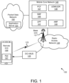
- Figure 1 depicts a wireless communication system 100 for waveform indication using DCI, according to embodiments of the disclosure.
- the wireless communication system 100 includes at least one remote unit 105, a radio access network ("RAN") 120, and a mobile core network 140.
- the RAN 120 and the mobile core network 140 form a mobile communication network.
- the RAN 120 may be composed of a base unit 121 with which the remote unit 105 communicates using wireless communication links 123.
- remote units 105 Even though a specific number of remote units 105, base units 121, wireless communication links 123, RANs 120, and mobile core networks 140 are depicted in Figure 1 , one of skill in the art will recognize that any number of remote units 105, base units 121, wireless communication links 123, RANs 120, and mobile core networks 140 may be included in the wireless communication system 100.
- the RAN 120 is compliant with the 5G system specified in the Third Generation Partnership Project ("3GPP") specifications.
- the RAN 120 may be a Next Generation Radio Access Network ("NG-RAN”), implementing New Radio (“NR”) Radio Access Technology (“RAT”) and/or Long-Term Evolution (“LTE”) RAT.
- the RAN 120 may include non-3GPP RAT (e.g., Wi-Fi ® or Institute of Electrical and Electronics Engineers (“IEEE”) 802.11-family compliant WLAN).
- the RAN 120 is compliant with the LTE system specified in the 3GPP specifications.
- the wireless communication system 100 may implement some other open or proprietary communication network, for example Worldwide Interoperability for Microwave Access (“WiMAX”) or IEEE 802.16-family standards, among other networks.
- WiMAX Worldwide Interoperability for Microwave Access
- IEEE 802.16-family standards among other networks.
- the present disclosure is not intended to be limited to the implementation of any particular wireless communication system architecture or protocol.
- the RAN node 210 may select the waveform (possibly including subcarrier spacing) based on some parameters such as the used carrier frequency, UE measurement (RSRP/RSRQ/SINR)/location, UE 205 and RAN node 210 RF capabilities, UE power status (e.g., PH report), UE assistance information (e.g., DL transform precoding recommendation based on PL estimate), indication of UE battery power status etc.
- UE battery can help the RAN node 210 to choose the right waveform, since some waveforms require higher signal processing reception complexity than others, and thus save some UE power at critical battery power status.
- the power saving offset (“PS-offset”) 310 is semi-statically configured before DRX ON time defining the start of the interval for the DCI with CRC scrambled by PS-RNTI ("DCP") monitoring occasion 315 as shown in Figure 3 .
- DCP PS-RNTI
- the UE 205 monitors the Search Space ((i.e., Search Space (“SS") Set 1) for DCP.
- SS Search Space
- more than one monitoring occasions 315 may be configured for DCP on the Primary Cell (“PCell”) for Carrier Aggregation (“CA”) and on Special Cell (“SpCell”) for Dual Connectivity (“DC”) based on the Search Space (i.e., Search Space (“SS”) Set 1) and Control Resource Set (“CORESET”) configurations.
- PCell Primary Cell
- CA Carrier Aggregation
- SpCell Special Cell
- DC Dual Connectivity
- multiple bits are added in DCI format 2_6 providing information about different single carrier waveforms or different multicarrier waveforms for DL physical channels.
- Figure 7 depicts a user equipment apparatus 700 that may be used for performing enhanced DM-RS configuration, according to embodiments of the disclosure.
- the user equipment apparatus 700 is used to implement one or more of the solutions described above.
- the user equipment apparatus 700 may be one embodiment of the remote unit 105 and/or the UE 205, described above.
- the user equipment apparatus 700 may include a processor 705, a memory 710, an input device 715, an output device 720, and a transceiver 725.
- the input device 715 and the output device 720 are combined into a single device, such as a touchscreen.
- the user equipment apparatus 700 may not include any input device 715 and/or output device 720.
- the user equipment apparatus 700 may include one or more of: the processor 705, the memory 710, and the transceiver 725, and may not include the input device 715 and/or the output device 720.
- the DCI uses one or more code points to provide information about the waveform type to be used for the reception of the physical downlink channel.
- the one or more code points indicate one of: a CORESET identifier, a search space identifier, and a DCI format, where the one or more code point further indicates a corresponding waveform type for reception of the identified CORESET, search space, and/or DCI format.
- receiving the downlink transmission during the next occurring DRX Active Time includes receiving a second waveform indication during the DRX Active Time, the second waveform indication indicating a first waveform type for use with a dormant BWP and a second waveform type for use with a non-dormant BWP.
- each BWP of a SCell is configured with a default waveform type, where a same default waveform type is configured for the physical downlink channel.
- the DCI containing the waveform indicator includes a code point configured for non-dormant BWP of each SCell in a group, where each bit in the code point corresponds to one of the SCells in the group.
- determining the waveform type for the next occurring DRX Active Time includes determining a waveform type for use by a dormant BWP for performing RRM measurements.
- the output device 720 may include a wearable display separate from, but communicatively coupled to, the rest of the user equipment apparatus 700, such as a smart watch, smart glasses, a heads-up display, or the like. Further, the output device 720 may be a component of a smart phone, a personal digital assistant, a television, a table computer, a notebook (laptop) computer, a personal computer, a vehicle dashboard, or the like.
- the output device 720 includes one or more speakers for producing sound.
- the output device 720 may produce an audible alert or notification (e.g., a beep or chime).
- the output device 720 includes one or more haptic devices for producing vibrations, motion, or other haptic feedback.
- all or portions of the output device 720 may be integrated with the input device 715.
- the input device 715 and output device 720 may form a touchscreen or similar touch-sensitive display.
- the output device 720 may be located near the input device 715.
- the transceiver 725 communicates with one or more network functions of a mobile communication network via one or more access networks.
- the transceiver 725 operates under the control of the processor 705 to transmit messages, data, and other signals and also to receive messages, data, and other signals.
- the processor 705 may selectively activate the transceiver 725 (or portions thereof) at particular times in order to send and receive messages.
- the transceiver 725 includes at least transmitter 730 and at least one receiver 735.
- One or more transmitters 730 may be used to provide UL communication signals to a base unit 121, such as the UL transmissions described herein.
- one or more receivers 735 may be used to receive DL communication signals from the base unit 121, as described herein.
- the user equipment apparatus 700 may have any suitable number of transmitters 730 and receivers 735.
- the transmitter(s) 730 and the receiver(s) 735 may be any suitable type of transmitters and receivers.
- the transceiver 725 includes a first transmitter/receiver pair used to communicate with a mobile communication network over licensed radio spectrum and a second transmitter/receiver pair used to communicate with a mobile communication network over unlicensed radio spectrum.
- the first transmitter/receiver pair used to communicate with a mobile communication network over licensed radio spectrum and the second transmitter/receiver pair used to communicate with a mobile communication network over unlicensed radio spectrum may be combined into a single transceiver unit, for example a single chip performing functions for use with both licensed and unlicensed radio spectrum.
- the first transmitter/receiver pair and the second transmitter/receiver pair may share one or more hardware components.
- certain transceivers 725, transmitters 730, and receivers 735 may be implemented as physically separate components that access a shared hardware resource and/or software resource, such as for example, the network interface 740.
- one or more transmitters 730 and/or one or more receivers 735 may be implemented and/or integrated into a single hardware component, such as a multi-transceiver chip, a system-on-a-chip, an Application-Specific Integrated Circuit ("ASIC"), or other type of hardware component.
- one or more transmitters 730 and/or one or more receivers 735 may be implemented and/or integrated into a multi-chip module.
- other components such as the network interface 740 or other hardware components/circuits may be integrated with any number of transmitters 730 and/or receivers 735 into a single chip.
- the transmitters 730 and receivers 735 may be logically configured as a transceiver 725 that uses one more common control signals or as modular transmitters 730 and receivers 735 implemented in the same hardware chip or in a multi-chip module.
- the input device 815 and the output device 820 are combined into a single device, such as a touchscreen.
- the network apparatus 800 may not include any input device 815 and/or output device 820.
- the network apparatus 800 may include one or more of: the processor 805, the memory 810, and the transceiver 825, and may not include the input device 815 and/or the output device 820.
- the transceiver 825 includes at least one transmitter 830 and at least one receiver 835.
- the transceiver 825 communicates with one or more remote units 85.
- the transceiver 825 may support at least one network interface 840 and/or application interface 845.
- the application interface(s) 845 may support one or more APIs.
- the network interface(s) 840 may support 3GPP reference points, such as Uu, N1, N2 and N3. Other network interfaces 840 may be supported, as understood by one of ordinary skill in the art.
- the network apparatus 800 is a RAN node (e.g., gNB) that communicates with one or more UEs, as described herein.
- the processor 805 controls the network apparatus 800 to perform the above described RAN behaviors.
- the processor 805 may include an application processor (also known as “main processor") which manages application-domain and operating system (“OS”) functions and a baseband processor (also known as “baseband radio processor”) which manages radio functions.
- the processor 805 determines a waveform type for a next occurring DRX Active Time for a UE.
- the processor 805 controls the transceiver 825 to transmit DCI outside any DRX Active Time of the UE, where the DCI contains a waveform indicator and to transmit a downlink transmission on a physical downlink channel (e.g., PDSCH and/or PDCCH) during the next occurring DRX Active Time using the determined waveform.
- a physical downlink channel e.g., PDSCH and/or PDCCH
- the DCI contains a DCI-WUS.
- the waveform indicator provides information about the usage of a single carrier waveform type or a multicarrier waveform type for reception of the physical downlink channel.
- the location of the waveform indicator within the DCI is semi-statically configured by higher layer signaling.
- the DCI uses one or more code points to provide information about the waveform type to be used for the reception of the physical downlink channel.
- the one or more code points indicate one of: a CORESET identifier, a search space identifier, and a DCI format, where the one or more code point further indicates a corresponding waveform type for reception of the identified CORESET, search space, and/or DCI format.
- transmitting the downlink transmission during the next occurring DRX Active Time includes transmitting a second waveform indication during the DRX Active Time, the second waveform indication indicating a first waveform type for use with a dormant BWP and a second waveform type for use with a non-dormant BWP.
- each BWP of a SCell is configured with a default waveform type, where a same default waveform type is configured for the physical downlink channel.
- the DCI containing the waveform indicator includes a code point configured for non-dormant BWP of each SCell in a group, where each bit in the code point corresponds to one of the SCells in the group.
- determining the waveform type for the next occurring DRX Active Time includes determining a waveform type for use by a dormant BWP for performing RRM measurements.
- the DCI containing the waveform indicator is transmitted using a same waveform type as used to transmit a CORESET for the same cell.
- the waveform indicator further indicates a waveform type to be used during the next DRX Active Time for a physical uplink channel.
- transmitting the downlink transmission during the next occurring DRX Active Time includes sending an uplink CG for the UE, where the uplink CG contains a second waveform indicator that indicates a waveform type to be used for uplink CG transmission.
- the memory 810 in one embodiment, is a computer readable storage medium.
- the memory 810 includes volatile computer storage media.
- the memory 810 may include a RAM, including dynamic RAM (“DRAM”), synchronous dynamic RAM (“SDRAM”), and/or static RAM (“SRAM”).
- the memory 810 includes non-volatile computer storage media.
- the memory 810 may include a hard disk drive, a flash memory, or any other suitable non-volatile computer storage device.
- the memory 810 includes both volatile and non-volatile computer storage media.
- the memory 810 stores data related to enhanced DM-RS configuration.
- the memory 810 may store parameters, configurations, resource assignments, policies, and the like, as described above.
- the memory 810 also stores program code and related data, such as an operating system or other controller algorithms operating on the apparatus 800.
- the input device 815 may include any known computer input device including a touch panel, a button, a keyboard, a stylus, a microphone, or the like.
- the input device 815 may be integrated with the output device 820, for example, as a touchscreen or similar touch-sensitive display.
- the input device 815 includes a touchscreen such that text may be input using a virtual keyboard displayed on the touchscreen and/or by handwriting on the touchscreen.
- the input device 815 includes two or more different devices, such as a keyboard and a touch panel.
- the output device 820 in one embodiment, is designed to output visual, audible, and/or haptic signals.
- the output device 820 includes an electronically controllable display or display device capable of outputting visual data to a user.
- the output device 820 may include, but is not limited to, an LCD display, an LED display, an OLED display, a projector, or similar display device capable of outputting images, text, or the like to a user.
- the output device 820 may include a wearable display separate from, but communicatively coupled to, the rest of the network apparatus 800, such as a smart watch, smart glasses, a heads-up display, or the like.
- the output device 820 may be a component of a smart phone, a personal digital assistant, a television, a table computer, a notebook (laptop) computer, a personal computer, a vehicle dashboard, or the like.
- the transceiver 825 includes at least transmitter 830 and at least one receiver 835.
- One or more transmitters 830 may be used to communicate with the UE, as described herein.
- one or more receivers 835 may be used to communicate with network functions in the PLMN and/or RAN, as described herein.
- the network apparatus 800 may have any suitable number of transmitters 830 and receivers 835.
- the transmitter(s) 830 and the receiver(s) 835 may be any suitable type of transmitters and receivers.
- Figure 9 depicts one embodiment of a method 900 for waveform indication using DCI, according to embodiments of the disclosure.
- the method 900 is performed by a user equipment device in a mobile communication network, such as the remote unit 105, the UE 205, and/or the user equipment apparatus 700, described above.
- the method 900 is performed by a processor, such as a microcontroller, a microprocessor, a CPU, a GPU, an auxiliary processing unit, a FPGA, or the like.
- the first apparatus may be implemented by a user equipment device in a mobile communication network, such as the remote unit 105, the UE 205, and/or the user equipment apparatus 800, described above.
- the first apparatus includes a transceiver and a processor that monitors for DCI outside a DRX Active Time, where the DCI contains a waveform indicator.
- the processor determines a waveform type for a next occurring DRX Active Time, and the transceiver receives a downlink transmission on a physical downlink channel (e.g., PDSCH and/or PDCCH) during the next occurring DRX Active Time using the determined waveform.
- a physical downlink channel e.g., PDSCH and/or PDCCH
- the DCI includes a DCI-WUS.
- the waveform indicator provides information about the usage of a single carrier waveform type or a multicarrier waveform type for reception of the physical downlink channel.
- the location of the waveform indicator within the DCI is semi-statically configured by higher layer signaling.
- receiving the downlink transmission during the next occurring DRX Active Time includes receiving a second waveform indication during the DRX Active Time, the second waveform indication indicating a first waveform type for use with a dormant BWP and a second waveform type for use with a non-dormant BWP.
- each BWP of a SCell is configured with a default waveform type, where a same default waveform type is configured for the physical downlink channel.
- the DCI containing the waveform indicator is received using a same waveform type as used to receive a CORESET for the same cell.
- the waveform indicator further indicates a waveform type to be used during the next DRX Active Time for a physical uplink channel.
- receiving the downlink transmission during the next occurring DRX Active Time includes receiving an uplink CG, where the uplink CG contains a second waveform indicator that indicates a waveform type to be used for uplink CG transmission.
- the DCI includes a DCI-WUS.
- the waveform indicator provides information about the usage of a single carrier waveform type or a multicarrier waveform type for reception of the physical downlink channel.
- the location of the waveform indicator within the DCI is semi-statically configured by higher layer signaling.
- determining the waveform type for the next occurring DRX Active Time includes using a default waveform type when no DCI containing a waveform indicator is received at least a threshold amount of time prior to the start of the next occurring DRX Active Time.
- the DCI contains a waveform indicator but is not received with a minimum time gap between the DCI-WUS and the next occurring DRX Active Time.
- the waveform indicator is absent from the DCI-WUS.
Landscapes
- Engineering & Computer Science (AREA)
- Signal Processing (AREA)
- Computer Networks & Wireless Communication (AREA)
- Mobile Radio Communication Systems (AREA)
Claims (15)
- Verfahren (900) einer Benutzerausrüstungsvorrichtung, UE, wobei das Verfahren umfasst:Überwachen (905) von Downlink-Steuerinformationen, DCI, außerhalb eines diskontinuierlichen Empfangs, DRX, DRX-Aktivzeit, wobei die DCI einen Wellenform indikator umfassen;Bestimmen (910) eines Wellenformtyps für eine nächste auftretende DRX-Aktivzeit; undEmpfangen (915) einer Downlink-Übertragung auf einem physischen Downlink-Kanal während der nächsten auftretenden DRX-Aktivzeit unter Verwendung der bestimmten Wellenform.
- Benutzerausrüstungseinrichtung (UE-Einrichtung) (700), umfassend:
einen Prozessor (705), der eingerichtet ist zum:Überwachen von Downlink-Steuerinformationen, DCI, außerhalb eines diskontinuierlichen Empfangs, DRX, DRX-Aktivzeit, wobei die DCI einen Wellenformindikator umfassen; undBestimmen eines Wellenformtyps für die nächste auftretende DRX-Aktivzeit; undeinen Transceiver (725), der dazu eingerichtet ist, während der nächsten auftretenden DRX-Aktivzeit unter Verwendung der bestimmten Wellenform eine Downlink-Übertragung auf einem physischen Downlink-Kanal zu empfangen. - UE-Einrichtung (700) nach Anspruch 2, wobei die DCI ein DCI-Wake-Up-Signal, DCI-WUS, umfassen.
- UE-Einrichtung (700) nach Anspruch 2, wobei der Wellenformindikator Informationen über die Nutzung eines Einzelträger-Wellenformtyps oder eines Mehrträger-Wellenformtyps für den Empfang des physischen Downlink-Kanals bereitstellt.
- UE-Einrichtung (700) nach Anspruch 2, wobei der Ort des Wellenformindikators innerhalb der DCI durch Signalisierung auf einer höheren Ebene halbstatisch konfiguriert ist.
- UE-Einrichtung (700) nach Anspruch 2, wobei die DCI einen oder mehrere Codepunkte verwenden, um Informationen über den Wellenformtyp bereitzustellen, der für den Empfang des physischen Downlink-Kanals verwendet werden soll.
- UE-Einrichtung (700) nach Anspruch 6, wobei der eine oder die mehreren Codepunkte eines der folgenden angeben:
eine Control Resource Set-, CORESET-, Kennung, eine Suchraumkennung und ein DCI-Format, wobei der eine oder die mehreren Codepunkte ferner einen entsprechenden Wellenformtyp für den Empfang des identifizierten CORESET-, Suchraum- und/oder DCI-Formats angeben. - UE-Einrichtung (700) nach Anspruch 2, wobei das Bestimmen des Wellenformtyps für die nächste auftretende DRX-Aktivzeit das Verwenden eines Standard-Wellenformtyps umfasst, wenn keine DCI, die einen Wellenformindikator umfassen, mindestens eine Schwellenzeitspanne vor dem Beginn der nächsten auftretenden DRX-Aktivzeit empfangen werden.
- UE-Einrichtung (700) nach Anspruch 2, wobei das Empfangen der Downlink-Übertragung während der nächsten auftretenden DRX-Aktivzeit das Empfangen einer zweiten Wellenformanzeige während der DRX-Aktivzeit umfasst, wobei die zweite Wellenformanzeige einen ersten Wellenformtyp zur Verwendung mit einem ruhenden Bandbreitenteil, BWP, und einen zweiten Wellenformtyp zur Verwendung mit einem nicht ruhenden BWP angibt.
- UE-Einrichtung (700) nach Anspruch 9, wobei jedes BWP einer sekundären Zelle, SCell, mit einem Standardwellenformtyp konfiguriert ist, wobei derselbe Standardwellenformtyp für den physischen Downlink-Kanal konfiguriert ist.
- UE-Einrichtung (700) nach Anspruch 2, wobei die DCI, die den Wellenformindikator umfassen, einen Codepunkt einschließt, der für das nicht ruhende BWP jeder sekundären Zelle, SCell, in einer Gruppe konfiguriert ist, wobei jedes Bit im Codepunkt einer der SCells in der Gruppe entspricht.
- UE-Einrichtung (700) nach Anspruch 2, wobei das Bestimmen des Wellenformtyps für die nächste auftretende DRX-Aktivzeit das Bestimmen eines Wellenformtyps zur Verwendung durch ein ruhendes BWP zum Durchführen von Radio Resource Management (RRM)-Messungen umfasst.
- UE-Einrichtung (700) nach Anspruch 2, wobei die DCI, die den Wellenformindikator umfassen, unter Verwendung desselben Wellenformtyps empfangen werden, der zum Empfangen eines Control Resource Set (CORESET) für dieselbe Zelle verwendet wird.
- UE-Einrichtung (700) nach Anspruch 2, wobei der Wellenformindikator ferner einen Wellenformtyp angibt, der während der nächsten DRX-Aktivzeit für einen physischen Uplink-Kanal verwendet werden soll.
- Funkzugangsnetz, RAN, inrichtung (800), umfassend:einen Prozessor (805), der dazu eingerichtet ist, einen Wellenformtyp für einen nächsten auftretenden diskontinuierlichen Empfang, DRX, DRX-Aktivzeit für eine Benutzereinrichtung, UE, zu bestimmen; undeinen Sendeempfänger (825), der eingerichtet ist zum:Übertragen von Downlink-Steuerinformationen, DCI, außerhalb einer DRX-Aktivzeit der UE, wobei die DCI einen Wellenformindikator umfassen; undÜbertragen, während der nächsten DRX-Aktivzeit, einer Downlink-Übertragung auf einem physischen Downlink-Kanal unter Verwendung der bestimmten Wellenform.
Applications Claiming Priority (2)
| Application Number | Priority Date | Filing Date | Title |
|---|---|---|---|
| US202063045011P | 2020-06-26 | 2020-06-26 | |
| PCT/IB2021/055720 WO2021260660A1 (en) | 2020-06-26 | 2021-06-26 | Waveform indication using dci |
Publications (3)
| Publication Number | Publication Date |
|---|---|
| EP4173375A1 EP4173375A1 (de) | 2023-05-03 |
| EP4173375C0 EP4173375C0 (de) | 2024-07-10 |
| EP4173375B1 true EP4173375B1 (de) | 2024-07-10 |
Family
ID=76744881
Family Applications (1)
| Application Number | Title | Priority Date | Filing Date |
|---|---|---|---|
| EP21737173.1A Active EP4173375B1 (de) | 2020-06-26 | 2021-06-26 | Wellenformanzeige mit dci |
Country Status (4)
| Country | Link |
|---|---|
| US (1) | US20230269664A1 (de) |
| EP (1) | EP4173375B1 (de) |
| CN (1) | CN115720719B (de) |
| WO (1) | WO2021260660A1 (de) |
Families Citing this family (9)
| Publication number | Priority date | Publication date | Assignee | Title |
|---|---|---|---|---|
| CN116506951A (zh) * | 2022-01-18 | 2023-07-28 | 维沃移动通信有限公司 | Bwp上的波形确定方法及终端 |
| CN116939618A (zh) * | 2022-04-08 | 2023-10-24 | 华为技术有限公司 | 一种通信方法及通信装置 |
| EP4515770A4 (de) * | 2022-04-29 | 2026-02-25 | Lenovo Beijing Ltd | Verfahren und vorrichtungen zur uplink-übertragung |
| CN119547514A (zh) | 2022-07-15 | 2025-02-28 | 诺基亚技术有限公司 | 波形管理 |
| CN117997481A (zh) * | 2022-11-03 | 2024-05-07 | 上海朗帛通信技术有限公司 | 一种被用于无线通信的节点中的方法和装置 |
| KR20240070776A (ko) * | 2022-11-14 | 2024-05-22 | 삼성전자주식회사 | 무선 통신 시스템에서 동적 파형 변경 지시 방법 및 장치 |
| EP4369668A1 (de) * | 2022-11-14 | 2024-05-15 | Nokia Technologies Oy | Verfahren zur ul-wellenformumschaltung mit gemeinsamem gruppen-dci |
| CN119011071B (zh) * | 2023-05-22 | 2026-01-27 | 中国电信股份有限公司北京研究院 | 辅助信息上报方法和系统、终端和计算机可读存储介质 |
| US12557024B2 (en) * | 2023-09-07 | 2026-02-17 | Qualcomm Incorporated | Low power wake-up signal for small data transfer |
Family Cites Families (12)
| Publication number | Priority date | Publication date | Assignee | Title |
|---|---|---|---|---|
| US8902830B2 (en) * | 2010-12-28 | 2014-12-02 | Motorola Mobility Llc | Energy-saving base station and method |
| CN104769857B (zh) * | 2012-11-01 | 2018-05-22 | Lg 电子株式会社 | 在无线通信系统中支持设备特性的调度组的方法和装置 |
| US10039055B2 (en) * | 2013-07-19 | 2018-07-31 | Lg Electronics Inc. | Method for monitoring a physical downlink control channel during DRX operation in a wireless communication system and a device therefor |
| US10849134B2 (en) * | 2016-11-04 | 2020-11-24 | Qualcomm Incorporated | Indicating a range of beam correspondence in a wireless node |
| US10623163B2 (en) * | 2017-03-31 | 2020-04-14 | Qualcomm Incorporated | Coexistence of control resource sets with different waveforms |
| US10644827B2 (en) * | 2017-04-06 | 2020-05-05 | Qualcomm Incorporated | Systems and methods for dynamic switching between waveforms on downlink |
| KR102383385B1 (ko) * | 2017-04-17 | 2022-04-08 | 삼성전자 주식회사 | 업링크 전력 제어를 위한 방법 및 장치 |
| CN108990166B (zh) * | 2017-05-05 | 2019-11-19 | 华为技术有限公司 | 一种获取控制信息的方法及装置 |
| CN110999479A (zh) * | 2018-08-03 | 2020-04-10 | Lg电子株式会社 | 在无线通信系统中发送和接收下行链路数据信道的方法和用于该方法的设备 |
| EP3797496B1 (de) * | 2018-08-10 | 2024-08-07 | Apple Inc. | Downlink-wellenform- und schutzintervallanpassung für ein drahtloses system |
| WO2020038546A1 (en) * | 2018-08-20 | 2020-02-27 | Nokia Technologies Oy | Multi-purpose wake-up signal in new radio |
| CN110958668B (zh) * | 2018-09-27 | 2021-11-05 | 大唐移动通信设备有限公司 | 一种终端状态转换方法、网络设备及终端 |
-
2021
- 2021-06-26 US US18/012,532 patent/US20230269664A1/en active Pending
- 2021-06-26 EP EP21737173.1A patent/EP4173375B1/de active Active
- 2021-06-26 CN CN202180044888.7A patent/CN115720719B/zh active Active
- 2021-06-26 WO PCT/IB2021/055720 patent/WO2021260660A1/en not_active Ceased
Also Published As
| Publication number | Publication date |
|---|---|
| US20230269664A1 (en) | 2023-08-24 |
| CN115720719A (zh) | 2023-02-28 |
| CN115720719B (zh) | 2026-04-28 |
| EP4173375A1 (de) | 2023-05-03 |
| EP4173375C0 (de) | 2024-07-10 |
| WO2021260660A1 (en) | 2021-12-30 |
Similar Documents
| Publication | Publication Date | Title |
|---|---|---|
| EP4173375B1 (de) | Wellenformanzeige mit dci | |
| EP4173420B1 (de) | Wellenformtyp einer steuersignalkonfiguration | |
| TWI848042B (zh) | 用於新無線電載波聚合的次細胞休眠 | |
| EP4169199B1 (de) | Leistungseffiziente pdcch-überwachung | |
| US12494881B2 (en) | Demodulation reference signal configuration | |
| US20230361894A1 (en) | Channel-sensing measurement and channel access report | |
| US20230319816A1 (en) | Inserting beam switching gaps between beam transmissions | |
| US20240172199A1 (en) | Indication of uplink transmission in downlink symbol | |
| US20240163058A1 (en) | Full duplex reference signal configuration | |
| US20230109827A1 (en) | Applying irregular subcarrier spacing | |
| US20240048333A1 (en) | Multiple default beams for multiple pdsch/pusch and multi-slot pdcch monitoring | |
| US20250106661A1 (en) | Configuration, measurement, and reporting for multiple waveform-based reference signals | |
| WO2022172177A1 (en) | Receiving csi-rs and pdsch using multiple dfts | |
| CN115997422A (zh) | 用于连接模式不连续接收切换的用户设备优化 | |
| US20240389037A1 (en) | Transmitting single-carrier synchronization signal block | |
| KR102802725B1 (ko) | 인위적 am/pm을 추가하는 것에 의한 l1 보안 | |
| US20250081232A1 (en) | Ue assistance for no-lbt based unlicensed channel access | |
| US20250105907A1 (en) | Multiple waveforms based qcl/tci framework | |
| US20240365260A1 (en) | Synchronization signal block groups associated with multiple waveforms for a wireless communication network supporting a high frequency range | |
| WO2023199294A1 (en) | Techniques for signal repetition using reconfigurable intelligent surfaces |
Legal Events
| Date | Code | Title | Description |
|---|---|---|---|
| STAA | Information on the status of an ep patent application or granted ep patent |
Free format text: STATUS: UNKNOWN |
|
| STAA | Information on the status of an ep patent application or granted ep patent |
Free format text: STATUS: THE INTERNATIONAL PUBLICATION HAS BEEN MADE |
|
| PUAI | Public reference made under article 153(3) epc to a published international application that has entered the european phase |
Free format text: ORIGINAL CODE: 0009012 |
|
| STAA | Information on the status of an ep patent application or granted ep patent |
Free format text: STATUS: REQUEST FOR EXAMINATION WAS MADE |
|
| 17P | Request for examination filed |
Effective date: 20221202 |
|
| AK | Designated contracting states |
Kind code of ref document: A1 Designated state(s): AL AT BE BG CH CY CZ DE DK EE ES FI FR GB GR HR HU IE IS IT LI LT LU LV MC MK MT NL NO PL PT RO RS SE SI SK SM TR |
|
| DAV | Request for validation of the european patent (deleted) | ||
| DAX | Request for extension of the european patent (deleted) | ||
| GRAP | Despatch of communication of intention to grant a patent |
Free format text: ORIGINAL CODE: EPIDOSNIGR1 |
|
| STAA | Information on the status of an ep patent application or granted ep patent |
Free format text: STATUS: GRANT OF PATENT IS INTENDED |
|
| INTG | Intention to grant announced |
Effective date: 20240208 |
|
| GRAS | Grant fee paid |
Free format text: ORIGINAL CODE: EPIDOSNIGR3 |
|
| GRAA | (expected) grant |
Free format text: ORIGINAL CODE: 0009210 |
|
| STAA | Information on the status of an ep patent application or granted ep patent |
Free format text: STATUS: THE PATENT HAS BEEN GRANTED |
|
| AK | Designated contracting states |
Kind code of ref document: B1 Designated state(s): AL AT BE BG CH CY CZ DE DK EE ES FI FR GB GR HR HU IE IS IT LI LT LU LV MC MK MT NL NO PL PT RO RS SE SI SK SM TR |
|
| REG | Reference to a national code |
Ref country code: CH Ref legal event code: EP |
|
| REG | Reference to a national code |
Ref country code: DE Ref legal event code: R096 Ref document number: 602021015533 Country of ref document: DE |
|
| U01 | Request for unitary effect filed |
Effective date: 20240729 |
|
| U07 | Unitary effect registered |
Designated state(s): AT BE BG DE DK EE FI FR IT LT LU LV MT NL PT SE SI Effective date: 20240812 |
|
| PG25 | Lapsed in a contracting state [announced via postgrant information from national office to epo] |
Ref country code: NO Free format text: LAPSE BECAUSE OF FAILURE TO SUBMIT A TRANSLATION OF THE DESCRIPTION OR TO PAY THE FEE WITHIN THE PRESCRIBED TIME-LIMIT Effective date: 20241010 |
|
| PG25 | Lapsed in a contracting state [announced via postgrant information from national office to epo] |
Ref country code: PL Free format text: LAPSE BECAUSE OF FAILURE TO SUBMIT A TRANSLATION OF THE DESCRIPTION OR TO PAY THE FEE WITHIN THE PRESCRIBED TIME-LIMIT Effective date: 20240710 Ref country code: GR Free format text: LAPSE BECAUSE OF FAILURE TO SUBMIT A TRANSLATION OF THE DESCRIPTION OR TO PAY THE FEE WITHIN THE PRESCRIBED TIME-LIMIT Effective date: 20241011 |
|
| PG25 | Lapsed in a contracting state [announced via postgrant information from national office to epo] |
Ref country code: IS Free format text: LAPSE BECAUSE OF FAILURE TO SUBMIT A TRANSLATION OF THE DESCRIPTION OR TO PAY THE FEE WITHIN THE PRESCRIBED TIME-LIMIT Effective date: 20241110 |
|
| PG25 | Lapsed in a contracting state [announced via postgrant information from national office to epo] |
Ref country code: HR Free format text: LAPSE BECAUSE OF FAILURE TO SUBMIT A TRANSLATION OF THE DESCRIPTION OR TO PAY THE FEE WITHIN THE PRESCRIBED TIME-LIMIT Effective date: 20240710 |
|
| PG25 | Lapsed in a contracting state [announced via postgrant information from national office to epo] |
Ref country code: RS Free format text: LAPSE BECAUSE OF FAILURE TO SUBMIT A TRANSLATION OF THE DESCRIPTION OR TO PAY THE FEE WITHIN THE PRESCRIBED TIME-LIMIT Effective date: 20241010 Ref country code: ES Free format text: LAPSE BECAUSE OF FAILURE TO SUBMIT A TRANSLATION OF THE DESCRIPTION OR TO PAY THE FEE WITHIN THE PRESCRIBED TIME-LIMIT Effective date: 20240710 |
|
| PG25 | Lapsed in a contracting state [announced via postgrant information from national office to epo] |
Ref country code: RS Free format text: LAPSE BECAUSE OF FAILURE TO SUBMIT A TRANSLATION OF THE DESCRIPTION OR TO PAY THE FEE WITHIN THE PRESCRIBED TIME-LIMIT Effective date: 20241010 Ref country code: PL Free format text: LAPSE BECAUSE OF FAILURE TO SUBMIT A TRANSLATION OF THE DESCRIPTION OR TO PAY THE FEE WITHIN THE PRESCRIBED TIME-LIMIT Effective date: 20240710 Ref country code: NO Free format text: LAPSE BECAUSE OF FAILURE TO SUBMIT A TRANSLATION OF THE DESCRIPTION OR TO PAY THE FEE WITHIN THE PRESCRIBED TIME-LIMIT Effective date: 20241010 Ref country code: IS Free format text: LAPSE BECAUSE OF FAILURE TO SUBMIT A TRANSLATION OF THE DESCRIPTION OR TO PAY THE FEE WITHIN THE PRESCRIBED TIME-LIMIT Effective date: 20241110 Ref country code: HR Free format text: LAPSE BECAUSE OF FAILURE TO SUBMIT A TRANSLATION OF THE DESCRIPTION OR TO PAY THE FEE WITHIN THE PRESCRIBED TIME-LIMIT Effective date: 20240710 Ref country code: GR Free format text: LAPSE BECAUSE OF FAILURE TO SUBMIT A TRANSLATION OF THE DESCRIPTION OR TO PAY THE FEE WITHIN THE PRESCRIBED TIME-LIMIT Effective date: 20241011 Ref country code: ES Free format text: LAPSE BECAUSE OF FAILURE TO SUBMIT A TRANSLATION OF THE DESCRIPTION OR TO PAY THE FEE WITHIN THE PRESCRIBED TIME-LIMIT Effective date: 20240710 |
|
| PG25 | Lapsed in a contracting state [announced via postgrant information from national office to epo] |
Ref country code: SM Free format text: LAPSE BECAUSE OF FAILURE TO SUBMIT A TRANSLATION OF THE DESCRIPTION OR TO PAY THE FEE WITHIN THE PRESCRIBED TIME-LIMIT Effective date: 20240710 Ref country code: RO Free format text: LAPSE BECAUSE OF FAILURE TO SUBMIT A TRANSLATION OF THE DESCRIPTION OR TO PAY THE FEE WITHIN THE PRESCRIBED TIME-LIMIT Effective date: 20240710 |
|
| PG25 | Lapsed in a contracting state [announced via postgrant information from national office to epo] |
Ref country code: CZ Free format text: LAPSE BECAUSE OF FAILURE TO SUBMIT A TRANSLATION OF THE DESCRIPTION OR TO PAY THE FEE WITHIN THE PRESCRIBED TIME-LIMIT Effective date: 20240710 |
|
| PG25 | Lapsed in a contracting state [announced via postgrant information from national office to epo] |
Ref country code: SK Free format text: LAPSE BECAUSE OF FAILURE TO SUBMIT A TRANSLATION OF THE DESCRIPTION OR TO PAY THE FEE WITHIN THE PRESCRIBED TIME-LIMIT Effective date: 20240710 |
|
| PLBE | No opposition filed within time limit |
Free format text: ORIGINAL CODE: 0009261 |
|
| STAA | Information on the status of an ep patent application or granted ep patent |
Free format text: STATUS: NO OPPOSITION FILED WITHIN TIME LIMIT |
|
| 26N | No opposition filed |
Effective date: 20250411 |
|
| PGFP | Annual fee paid to national office [announced via postgrant information from national office to epo] |
Ref country code: GB Payment date: 20250617 Year of fee payment: 5 |
|
| U20 | Renewal fee for the european patent with unitary effect paid |
Year of fee payment: 5 Effective date: 20250624 |
|
| REG | Reference to a national code |
Ref country code: CH Ref legal event code: H13 Free format text: ST27 STATUS EVENT CODE: U-0-0-H10-H13 (AS PROVIDED BY THE NATIONAL OFFICE) Effective date: 20260127 |
|
| PG25 | Lapsed in a contracting state [announced via postgrant information from national office to epo] |
Ref country code: MC Free format text: LAPSE BECAUSE OF FAILURE TO SUBMIT A TRANSLATION OF THE DESCRIPTION OR TO PAY THE FEE WITHIN THE PRESCRIBED TIME-LIMIT Effective date: 20240710 |
|
| PG25 | Lapsed in a contracting state [announced via postgrant information from national office to epo] |
Ref country code: IE Free format text: LAPSE BECAUSE OF NON-PAYMENT OF DUE FEES Effective date: 20250626 |
|
| PG25 | Lapsed in a contracting state [announced via postgrant information from national office to epo] |
Ref country code: CH Free format text: LAPSE BECAUSE OF NON-PAYMENT OF DUE FEES Effective date: 20250630 |