EP4173470A1 - Dispositif d'ajustement d'un pignon d'un entraînement à chaîne - Google Patents
Dispositif d'ajustement d'un pignon d'un entraînement à chaîne Download PDFInfo
- Publication number
- EP4173470A1 EP4173470A1 EP22200451.7A EP22200451A EP4173470A1 EP 4173470 A1 EP4173470 A1 EP 4173470A1 EP 22200451 A EP22200451 A EP 22200451A EP 4173470 A1 EP4173470 A1 EP 4173470A1
- Authority
- EP
- European Patent Office
- Prior art keywords
- externally threaded
- chain
- bearing
- rotary bearing
- drive
- Prior art date
- Legal status (The legal status is an assumption and is not a legal conclusion. Google has not performed a legal analysis and makes no representation as to the accuracy of the status listed.)
- Pending
Links
Images


Classifications
-
- A—HUMAN NECESSITIES
- A01—AGRICULTURE; FORESTRY; ANIMAL HUSBANDRY; HUNTING; TRAPPING; FISHING
- A01F—PROCESSING OF HARVESTED PRODUCE; HAY OR STRAW PRESSES; DEVICES FOR STORING AGRICULTURAL OR HORTICULTURAL PRODUCE
- A01F15/00—Baling presses for straw, hay or the like
- A01F15/08—Details
-
- F—MECHANICAL ENGINEERING; LIGHTING; HEATING; WEAPONS; BLASTING
- F16—ENGINEERING ELEMENTS AND UNITS; GENERAL MEASURES FOR PRODUCING AND MAINTAINING EFFECTIVE FUNCTIONING OF MACHINES OR INSTALLATIONS; THERMAL INSULATION IN GENERAL
- F16H—GEARING
- F16H55/00—Elements with teeth or friction surfaces for conveying motion; Worms, pulleys or sheaves for gearing mechanisms
- F16H55/02—Toothed members; Worms
- F16H55/30—Chain-wheels
-
- A—HUMAN NECESSITIES
- A01—AGRICULTURE; FORESTRY; ANIMAL HUSBANDRY; HUNTING; TRAPPING; FISHING
- A01F—PROCESSING OF HARVESTED PRODUCE; HAY OR STRAW PRESSES; DEVICES FOR STORING AGRICULTURAL OR HORTICULTURAL PRODUCE
- A01F15/00—Baling presses for straw, hay or the like
- A01F15/08—Details
- A01F15/0841—Drives for balers
- A01F15/085—Drives for balers for round balers
-
- F—MECHANICAL ENGINEERING; LIGHTING; HEATING; WEAPONS; BLASTING
- F16—ENGINEERING ELEMENTS AND UNITS; GENERAL MEASURES FOR PRODUCING AND MAINTAINING EFFECTIVE FUNCTIONING OF MACHINES OR INSTALLATIONS; THERMAL INSULATION IN GENERAL
- F16C—SHAFTS; FLEXIBLE SHAFTS; ELEMENTS OR CRANKSHAFT MECHANISMS; ROTARY BODIES OTHER THAN GEARING ELEMENTS; BEARINGS
- F16C25/00—Bearings for exclusively rotary movement adjustable for wear or play
- F16C25/02—Sliding-contact bearings
- F16C25/04—Sliding-contact bearings self-adjusting
-
- F—MECHANICAL ENGINEERING; LIGHTING; HEATING; WEAPONS; BLASTING
- F16—ENGINEERING ELEMENTS AND UNITS; GENERAL MEASURES FOR PRODUCING AND MAINTAINING EFFECTIVE FUNCTIONING OF MACHINES OR INSTALLATIONS; THERMAL INSULATION IN GENERAL
- F16H—GEARING
- F16H55/00—Elements with teeth or friction surfaces for conveying motion; Worms, pulleys or sheaves for gearing mechanisms
- F16H55/02—Toothed members; Worms
- F16H55/30—Chain-wheels
- F16H55/303—Chain-wheels for round linked chains, i.e. hoisting chains with identical links
-
- F—MECHANICAL ENGINEERING; LIGHTING; HEATING; WEAPONS; BLASTING
- F16—ENGINEERING ELEMENTS AND UNITS; GENERAL MEASURES FOR PRODUCING AND MAINTAINING EFFECTIVE FUNCTIONING OF MACHINES OR INSTALLATIONS; THERMAL INSULATION IN GENERAL
- F16H—GEARING
- F16H7/00—Gearings for conveying rotary motion by endless flexible members
- F16H7/06—Gearings for conveying rotary motion by endless flexible members with chains
-
- F—MECHANICAL ENGINEERING; LIGHTING; HEATING; WEAPONS; BLASTING
- F16—ENGINEERING ELEMENTS AND UNITS; GENERAL MEASURES FOR PRODUCING AND MAINTAINING EFFECTIVE FUNCTIONING OF MACHINES OR INSTALLATIONS; THERMAL INSULATION IN GENERAL
- F16H—GEARING
- F16H7/00—Gearings for conveying rotary motion by endless flexible members
- F16H7/08—Means for varying tension of belts, ropes or chains
-
- A—HUMAN NECESSITIES
- A01—AGRICULTURE; FORESTRY; ANIMAL HUSBANDRY; HUNTING; TRAPPING; FISHING
- A01F—PROCESSING OF HARVESTED PRODUCE; HAY OR STRAW PRESSES; DEVICES FOR STORING AGRICULTURAL OR HORTICULTURAL PRODUCE
- A01F15/00—Baling presses for straw, hay or the like
- A01F15/08—Details
- A01F15/18—Endless belts, rolls or the like
- A01F2015/186—Constructional details of rollers or the bearings of the rollers of the press chamber
-
- F—MECHANICAL ENGINEERING; LIGHTING; HEATING; WEAPONS; BLASTING
- F16—ENGINEERING ELEMENTS AND UNITS; GENERAL MEASURES FOR PRODUCING AND MAINTAINING EFFECTIVE FUNCTIONING OF MACHINES OR INSTALLATIONS; THERMAL INSULATION IN GENERAL
- F16H—GEARING
- F16H7/00—Gearings for conveying rotary motion by endless flexible members
- F16H7/08—Means for varying tension of belts, ropes or chains
- F16H2007/0863—Finally actuated members, e.g. constructional details thereof
- F16H2007/0865—Pulleys
-
- F—MECHANICAL ENGINEERING; LIGHTING; HEATING; WEAPONS; BLASTING
- F16—ENGINEERING ELEMENTS AND UNITS; GENERAL MEASURES FOR PRODUCING AND MAINTAINING EFFECTIVE FUNCTIONING OF MACHINES OR INSTALLATIONS; THERMAL INSULATION IN GENERAL
- F16H—GEARING
- F16H7/00—Gearings for conveying rotary motion by endless flexible members
- F16H7/08—Means for varying tension of belts, ropes or chains
- F16H2007/0889—Path of movement of the finally actuated member
- F16H2007/0893—Circular path
Definitions
- the invention relates to a device for adjusting a chain wheel of a chain drive, in particular a chain drive for driving press rollers or press belts of a round baler for pressing crops.
- the device comprises a trunnion with a free end and a fixed end, a rotary bearing arranged on the trunnion, and a sprocket wheel guided on the rotary bearing.
- round balers with a fixed pressing chamber are characterized in that a plurality of pressing rollers are arranged over the circumference of a defined cylindrical pressing chamber, which delimit the pressing chamber in the circumferential direction.
- the cylindrical pressing chamber is delimited at the end faces by respective side walls.
- Round balers with variable bale chambers are characterized in that the cylindrical bale chamber is delimited by one or more press belts in the circumferential direction, with the press belt being guided over several rollers.
- the cylindrical pressing chamber is also delimited by respective side walls at the end faces. It is also known to drive or rotate both the press rollers of a round baler with a fixed press chamber and the rollers of a round baler with a variable press chamber via a chain drive.
- chain drives are arranged on a frame of the round baler on one or both side walls outside of the baling chamber.
- the chain drive comprises a plurality of toothed wheels or sprockets which are connected to the press rollers or rollers, the sprockets being drive-connected via one or more drive chains.
- Such a round baler is, for example, from DE 196 32 762 A1 known. It shows a drive device for the press rollers of a round baler, which delimit a press chamber, wherein several chain drives are provided.
- the individual chain drives are each used to drive one Partial number of the press rollers to be driven in total, with drive sprockets for driving the individual chain drives being drivable together.
- the chain wheels intended for driving the press rollers are arranged on an arc of a circle in a lateral housing part of the round baler and the chain drives are attached parallel to one another.
- EP 2 952 089 A1 Another prior art round baler is shown EP 2 952 089 A1 , in which several press rollers are arranged around a press chamber and carry sprockets driven by a chain drive with a common chain. At least one of the sprockets and the associated press roller have cooperating guide means in the form of external shaft teeth on the press roller and cooperating hub internal teeth on the sprocket, which positively connect the sprocket and the press roller in the direction of rotation and allow the sprocket to move in the axial direction of the press roller.
- means for fixing the axial position of the chain wheel are provided in the form of a shaft nut fastened to the press roll stub and an external toothing engaging therewith.
- the design of the press rollers and sprockets disclosed here is suitable for drive-transmitting sprockets, but proves to be expensive in terms of cost and manufacture. However, it meets the requirement for axial adjustability of the sprockets for fine adjustment within the chain drive.
- sprockets are free-running and are usually guided on a rotary bearing, which is mounted on a bearing pin extending from the frame of the round baler or on a bearing pin of a chain tensioning device.
- Such free-running sprockets must also be subjected to fine axial adjustment in order to lie precisely in the course of the chain.
- the fine adjustment of the sprockets mounted on the bearing journal is usually done by means of spacer discs that are mounted on the bearing journal on both sides of the end faces of the rotary bearing, as is known, for example, from the assembly of the chain drives on a John Deere round baler of the type F441R.
- the object on which the invention is based is seen in specifying a device for the axial fine adjustment of a free-running chain wheel of a chain drive of a round baler, by means of which the aforementioned problems are overcome.
- a device of the type mentioned at the outset is designed in such a way that the bearing journal has a first externally threaded area and a second externally threaded area, with a threaded nut being arranged on each of the externally threaded areas, with which the rotary bearing is clamped on the bearing journal between the externally threaded areas.
- the arrangement of threaded nuts on both sides axially of the rotary bearing enables precise axial displacement of the rotary bearing by simply turning the threaded nuts.
- An axial fine adjustment of the sprocket is independent of a gauge (or thickness) of a shim. A time-consuming disassembly of the sprocket or the rotary bearing from the bearing pin, for example to place a thicker or thinner spacer disc between the sprocket and the frame, is no longer necessary.
- a spacer element can be provided between a threaded nut and a corresponding end face side of the rotary bearing.
- the spacer is placed between the threaded nut and the corresponding face of the rotary bearing so that the threaded nut does not come into direct contact with the rotary bearing. This avoids a transfer of rotation to the threaded nut and a loosening of the threaded nut due to vibration and rotational movements of the rotary bearing during operation.
- the axial coarse positioning of the sprocket on the bearing journal can be designed very variably by the spacer element, with the same design of the threads on bearing journals of the same length, without having to change the position of the threaded nuts excessively. In this way, the number of threads on the bearing journal and thus also the production costs for the external thread on the bearing journal can be minimized and an adjustment range can be made variable.
- a simple embodiment of a spacer element is a bushing, sleeve or disc that is pushed onto the bearing journal and clamped between the threaded nut and the end face of the rotary bearing, on one side or also on both sides of the rotary bearing.
- a further embodiment provides for the use of one or more plate springs, which can serve as spacer elements, and these can be arranged in addition to or instead of the spacer elements mentioned above.
- One or more cup springs put the threaded nuts under a certain tension, which provides additional anti-rotation protection against the threaded nuts coming loose.
- a spring-loaded axial displacement of the chain wheel can also be achieved if a plate spring is only arranged on one side of the rotary bearing.
- adjusting the threaded nut arranged on the opposite side of the diaphragm spring causes compression or expansion of the diaphragm spring.
- Adjusting the threaded nut is caused by an associated increasing or decreasing spring tension axial displacement of the rotary bearing on the journal.
- the described axial displacement of the rotary bearing can already be achieved by adjusting just one of the threaded nuts.
- the diameter of the first externally threaded portion is larger than the diameter of the second externally threaded portion, the second externally threaded portion extending from the free end of the bearing journal and the first externally threaded portion extending between the fixed end and the rotary bearing.
- Different diameters of the externally threaded sections starting from a smaller diameter at the free end of the bearing journal, allow assembly of the device by only accessing the free end of the bearing journal. This enables the fixed end of the bearing journal to be fastened to the frame of the round baler in a non-removable manner, for example by a welded connection or as a cast or forged part of a frame part of the frame.
- a bearing journal area without a thread is preferably provided between the externally threaded areas of the bearing journal, on which bearing the rotary bearing is accommodated.
- the bearing journal area on which the rotary bearing is accommodated can be manufactured independently of the threaded areas and with different sizes in diameter and adapted to an optimal fit for the rotary bearing.
- an internally threaded area is provided, to which a clamping plate is attached via a clamping screw, with the rotary bearing on the bearing journal between is clamped between the external thread area and the clamping plate.
- the clamping function of the threaded nut on the second externally threaded area of the previous example is replaced by the clamping plate.
- a spacer element can also be provided here between the threaded nut and/or the clamping plate and a corresponding end face side of the rotary bearing, with the spacer element also being able to be designed accordingly as a bushing, sleeve, disc or plate spring.
- the device described above is particularly suitable for use in a chain drive for driving press rollers or press belts of a round baler for pressing crops.
- the device can be used on one or more sprockets of the chain drive.
- the chain drive mentioned above can be used in many types of agricultural machinery in which rollers, rollers, drums or other rotary bodies have to be driven. However, it is particularly suitable for use in a round baler with a frame, a baling chamber and press rollers or press belts arranged on the frame and surrounding the baling chamber for pressing crops, with the chain drive on the frame and/or a side wall of the round baler for driving the press rollers or of the press belt is arranged.
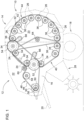
- the round baler 10 shown has a front part 12 and a rear part 14 .
- the round baler 10 further includes a frame 16, a chassis 18, a tongue 20, side walls 22 at the front part 12, side walls 23 at the rear part 14, nip rollers 24 at the front part 12, nip rollers 26 at the rear part 14, a feed assembly 28 for receiving of a harvested crop and a drive device 30.
- the frame 16 consists of struts and the like which hold and support the aforementioned components together and thus form the front part 12 into a unit.
- the chassis 18 is composed, not specified, of an axle and wheels attached thereto, which are located in the lower rear area of the front part 12 and support the entire round baler 10 on the ground in a mobile manner.
- the drawbar 20 is used to connect the round baler 10 to a towing vehicle, e.g. B. on a tractor, and is fixed to the frame 16 connected.
- the side walls 22, 23 are also firmly connected to the frame 16 and close a bale chamber 32 at the front.
- the side walls 22, 23 are at a distance from one another and accommodate the press rollers 24 and 26 in a movable manner.
- a bearing (not shown) is provided, which serves to connect the rear part 14 in a vertically pivotable manner.
- the side walls 22, 23 are connected to one another by transverse struts, which are not described in any more detail but are well known.
- the press rollers 24 and 26 are composed in a known manner of a metal jacket and a shaft or shaft stubs.
- the centers of the press rollers 24 and 26, ie their axes of rotation lie essentially on part of a circle which surrounds the press chamber 32.
- the chain wheels 34 of the press rollers 24 are surrounded by a drive chain 38 of a first chain drive 40 .
- the chain wheels 36 of the press rollers 26 are surrounded by a drive chain 42 of a second chain drive 44 .
- Another drive chain 46 of a third chain drive 48 serves to drive the first and second chain drive 40 and 44.
- the third chain drive 48 is driven by a main drive sprocket 50 which is connected to the drive device 30.
- the third chain drive 48 drives a first drive sprocket 52 which serves to drive the first chain drive 40 .
- the third chain drive 48 also drives a second drive sprocket 54 which serves to drive the second chain drive 44 .
- the first and second drive sprockets 52 and 54 are each double-toothed, with a first toothing of the first drive sprocket 52 and a first toothing of the second drive sprocket 54 being connected to the third chain drive 48 .
- a second toothing of the first drive sprocket 52 is in contact with the first Chain drive 40 in connection and drives it.
- a second toothing of the second drive chain wheel 54 is connected to the second chain drive 44 and drives it.
- the drive device 28 is in a manner not shown by the towing vehicle, z. B. via a cardan shaft, and contains a transverse shaft 56 in the rear area of the drawbar 20.
- the main drive chain wheel 50 which drives the third chain drive 48, extends from the shaft 56.
- the chain drives 40, 44 and 48 are tensioned via additional sprockets 58, 60, 62, 64 and by means of tensioning devices, which are not specified in detail. Furthermore, a chain wheel 66 is provided for the first chain drive 40 and a chain wheel 68 for the second chain drive 44 for guiding or deflecting the respective drive chains 38, 42.
- devices 70 are each shown for adjusting the additional sprockets 58, 60, 62, 64, 66 and 68, with the sprockets 58, 60, 62, 64, 66 and 68 each being arranged on a bearing journal 72 of such a device 70.
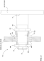
- the device 70 comprises a rotary bearing 74 arranged on the bearing journal 72 and the chain wheel 58, 60, 62, 64 guided on the rotary bearing 74, 66 and 68.
- the trunnion 72 comprises a free end 76 and a fixed end 78.
- the bearing journal is fixed to the frame 16, to the side walls 22, 23 or to a clamping arm 80 of a clamping device (unspecified).
- the bearing journal can be attached in any form in a removable (detachable) manner or in a non-detachable manner, for example by welding or by a connection produced in the casting or forging process of the clamping arm 80 .
- the bearing journal 72 also has a first externally threaded area 82 and a second externally threaded area 84, the diameter of the first externally threaded area (82) being larger than the diameter of the second externally threaded area (84).
- first threaded nut 86 On the externally threaded portion 82 is a first threaded nut 86 and on the second A second threaded nut 88 is screwed onto the externally threaded area 84 .
- a first spacer element 92 in the form of a spacer sleeve or bushing is provided between the first threaded nut 86 and an end face 90 of the rotary bearing 74 facing it.
- a second spacer element 96 is also provided in the form of a spacer sleeve or bushing.
- the spacer elements 92 and 96 can also be designed here as spacers or washers.
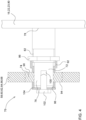
- the first spacer element 92 is replaced by a pair of plate springs 98 .
- One or more plate springs 98 can be arranged one behind the other.
- the second spacer element 96 could also be replaced by one or more cup springs 98 .
- FIG. 4 Further alternative embodiments are in figure 4 or figure 5 shown.
- the second externally threaded portion 84 and the second nut 88 from figures 2 and 3 replaced by an internally threaded area 100 provided at the free end 76 of the bearing journal 72 with a clamping screw 102 enclosed therein and a clamping plate 104 .
- the internal thread on the internal thread area 100 in combination with the clamping screw 102 and the clamping plate 104 develop the same technical effect as the previously described second threaded nut 88 in combination with the second external thread area 84, with the rotary bearing 74 on the bearing journal 72 between the first external thread area 82 and the Clamping plate 104 is clamped.
- a spacer element 92, 96, 98 can also be provided here between the first threaded nut 86 and/or the clamping plate 104 and the corresponding end face 90, 94 of the rotary bearing 74, the spacer element 92, 96, 98 being correspondingly also available as a bush, sleeve, Disk or plate spring can be formed.
- the position of the rotary bearing 74 can be changed axially to the bearing journal 72 and a fine adjustment of the rotary bearing and thus the axial position of the chain wheel to the bearing journal 74 can be made.
- disk springs 98 are provided as spacer elements, then due to the preload applied by disk spring 98, an axial displacement of rotary bearing 74 can be achieved by adjusting only one threaded nut 86, 88 or by adjusting only clamping screw 104 (in the case of the exemplary embodiment in figure 5 ) be achieved.
Landscapes
- Engineering & Computer Science (AREA)
- General Engineering & Computer Science (AREA)
- Mechanical Engineering (AREA)
- Life Sciences & Earth Sciences (AREA)
- Environmental Sciences (AREA)
- Gears, Cams (AREA)
Applications Claiming Priority (2)
| Application Number | Priority Date | Filing Date | Title |
|---|---|---|---|
| DE102021128386.8A DE102021128386A1 (de) | 2021-10-29 | 2021-10-29 | Vorrichtung zum Justieren eines Kettenrades eines Kettentriebs |
| DE102021128389.2A DE102021128389A1 (de) | 2021-10-29 | 2021-10-29 | Vorrichtung zum Justieren eines Kettenrades eines Kettentriebs |
Publications (1)
| Publication Number | Publication Date |
|---|---|
| EP4173470A1 true EP4173470A1 (fr) | 2023-05-03 |
Family
ID=83689682
Family Applications (2)
| Application Number | Title | Priority Date | Filing Date |
|---|---|---|---|
| EP22200451.7A Pending EP4173470A1 (fr) | 2021-10-29 | 2022-10-10 | Dispositif d'ajustement d'un pignon d'un entraînement à chaîne |
| EP22200452.5A Pending EP4173471A1 (fr) | 2021-10-29 | 2022-10-10 | Dispositif d'ajustement d'un pignon d'un entraînement à chaîne |
Family Applications After (1)
| Application Number | Title | Priority Date | Filing Date |
|---|---|---|---|
| EP22200452.5A Pending EP4173471A1 (fr) | 2021-10-29 | 2022-10-10 | Dispositif d'ajustement d'un pignon d'un entraînement à chaîne |
Country Status (2)
| Country | Link |
|---|---|
| US (2) | US12422023B2 (fr) |
| EP (2) | EP4173470A1 (fr) |
Families Citing this family (2)
| Publication number | Priority date | Publication date | Assignee | Title |
|---|---|---|---|---|
| US20250322746A1 (en) * | 2024-04-15 | 2025-10-16 | Fca Us Llc | Driver aggression and energy use monitoring during use of vehicle |
| EP4666841A1 (fr) * | 2024-06-17 | 2025-12-24 | Deere & Company | Dispositif pour un entraînement par chaîne, entraînement par chaîne et presse à balles |
Citations (7)
| Publication number | Priority date | Publication date | Assignee | Title |
|---|---|---|---|---|
| GB189717578A (en) * | 1897-07-27 | 1897-09-11 | William Thomas Whiteman | Vehicle Wheel Brake. |
| GB190204923A (en) * | 1902-02-26 | 1902-06-05 | George Lee Phelps | Improvements in Fly-wheels specially adapted for Harvesting Machines. |
| GB191117241A (en) * | 1911-07-28 | 1912-04-25 | John Mcgille Lamb | Improvements in or relating to Means for Facilitating the Detachment of the Wheels of Cycles, Motor-cycles and like Vehicles. |
| GB115153A (en) * | 1917-07-24 | 1918-05-02 | Improvements in or relating to wheels for motor vehicles | |
| DE19632762A1 (de) | 1996-08-14 | 1998-02-19 | Gkn Walterscheid Getriebe Gmbh | Antriebsvorrichtung für die Rollen einer Rundballenpresse |
| CN201640029U (zh) * | 2009-12-09 | 2010-11-24 | 广东海洋大学 | 高密度饲草圆捆打捆机 |
| EP2952089A1 (fr) | 2014-06-05 | 2015-12-09 | Usines Claas France S.A.S | Presse à balles rondes |
Family Cites Families (24)
| Publication number | Priority date | Publication date | Assignee | Title |
|---|---|---|---|---|
| DE278610C (fr) * | ||||
| GB191211381A (en) | 1912-05-13 | 1913-04-24 | Joseph Tudor Richards | Improvements in or relating to Vats for Use in Making Cheese. |
| GB290718A (en) * | 1927-02-16 | 1928-05-16 | Walter Dunn | Improvements in or relating to machines for distributing manure, seed and the like |
| US2127031A (en) | 1933-06-27 | 1938-08-16 | Carl E Johnson | Variable-speed unit |
| US2343084A (en) | 1940-07-27 | 1944-02-29 | Brown & Sharpe Mfg | Tightening device for sprocket chains, belts, and the like |
| US3110379A (en) | 1959-03-11 | 1963-11-12 | Gregory Ind | Bicycle brake |
| US3597988A (en) * | 1969-10-27 | 1971-08-10 | Portec Inc | Self-aligning sprocket |
| US3709466A (en) | 1971-02-08 | 1973-01-09 | A Dowrelio | Anchor hoist |
| US3789593A (en) * | 1972-12-07 | 1974-02-05 | Sperry Rand Corp | Hay rolling machine with pickup means |
| JPS549824Y2 (fr) | 1975-12-02 | 1979-05-09 | ||
| US4069719A (en) * | 1976-06-18 | 1978-01-24 | Cancilla Philip S | Chain tensioner for chain drives |
| US4488636A (en) | 1980-08-30 | 1984-12-18 | Sperry Corporation | Feeder mechanism for agricultural baler |
| DE4238296A1 (de) * | 1992-11-13 | 1994-05-19 | Bleichert Foerderanlagen Gmbh | Staurollenbahn |
| KR200216564Y1 (ko) * | 1998-11-24 | 2001-04-02 | 진세동 | 라미네이터 롤러의 압착롤러 슬립장치 |
| US6272825B1 (en) | 1999-09-15 | 2001-08-14 | Hay & Forage Industries | Round baler having hydraulically sequenced clutch and tailgate cylinders |
| KR200263252Y1 (ko) * | 2001-02-21 | 2002-02-04 | 이황철 | 냉동 냉장형 빙삭기 |
| KR20030078251A (ko) * | 2002-03-28 | 2003-10-08 | 현대자동차주식회사 | 무단변속기의 벨트 및 풀리의 자동 정열 조정장치 |
| US7444747B2 (en) * | 2004-10-14 | 2008-11-04 | Vermeer Manufacturing Company | Roller mount arrangement |
| CN201566850U (zh) * | 2009-11-03 | 2010-09-01 | 广东海洋大学 | 兼用型缠绕裹膜机 |
| JP5427643B2 (ja) * | 2010-02-24 | 2014-02-26 | 本田技研工業株式会社 | カラー部材の組付け構造 |
| US20170112321A1 (en) * | 2015-10-22 | 2017-04-27 | Corey John Murray Brown | Cooking Device Shaft Assembly |
| CN208839667U (zh) * | 2018-09-20 | 2019-05-10 | 郑州长城冶金设备有限公司 | 一种辊式破碎机 |
| JP7299476B2 (ja) | 2019-03-25 | 2023-06-28 | 株式会社椿本チエイン | スプロケット及び伝動機構 |
| DE102020209370A1 (de) | 2019-08-08 | 2021-02-11 | Sram Deutschland Gmbh | Fahrrad-Schaltwerk, insbesondere mit Feder-Dämpfer-Baugruppe |
-
2022
- 2022-09-14 US US17/931,926 patent/US12422023B2/en active Active
- 2022-09-14 US US17/931,922 patent/US12379022B2/en active Active
- 2022-10-10 EP EP22200451.7A patent/EP4173470A1/fr active Pending
- 2022-10-10 EP EP22200452.5A patent/EP4173471A1/fr active Pending
Patent Citations (7)
| Publication number | Priority date | Publication date | Assignee | Title |
|---|---|---|---|---|
| GB189717578A (en) * | 1897-07-27 | 1897-09-11 | William Thomas Whiteman | Vehicle Wheel Brake. |
| GB190204923A (en) * | 1902-02-26 | 1902-06-05 | George Lee Phelps | Improvements in Fly-wheels specially adapted for Harvesting Machines. |
| GB191117241A (en) * | 1911-07-28 | 1912-04-25 | John Mcgille Lamb | Improvements in or relating to Means for Facilitating the Detachment of the Wheels of Cycles, Motor-cycles and like Vehicles. |
| GB115153A (en) * | 1917-07-24 | 1918-05-02 | Improvements in or relating to wheels for motor vehicles | |
| DE19632762A1 (de) | 1996-08-14 | 1998-02-19 | Gkn Walterscheid Getriebe Gmbh | Antriebsvorrichtung für die Rollen einer Rundballenpresse |
| CN201640029U (zh) * | 2009-12-09 | 2010-11-24 | 广东海洋大学 | 高密度饲草圆捆打捆机 |
| EP2952089A1 (fr) | 2014-06-05 | 2015-12-09 | Usines Claas France S.A.S | Presse à balles rondes |
Also Published As
| Publication number | Publication date |
|---|---|
| EP4173471A1 (fr) | 2023-05-03 |
| US20230132573A1 (en) | 2023-05-04 |
| US12379022B2 (en) | 2025-08-05 |
| US12422023B2 (en) | 2025-09-23 |
| US20230133649A1 (en) | 2023-05-04 |
Similar Documents
| Publication | Publication Date | Title |
|---|---|---|
| EP0295449B1 (fr) | Dispositif pour imprimer ou découper à l'emporte-pièce une bande | |
| CH627951A5 (de) | Walzenstuhl fuer die schrotung und vermahlung von getreide. | |
| DE19517955A1 (de) | Fahrzeugachsen-Differential | |
| EP4173471A1 (fr) | Dispositif d'ajustement d'un pignon d'un entraînement à chaîne | |
| DE19751117A1 (de) | Vorrichtung zur Vermeidung von Spiel zwischen den kämmenden Zähnen eines ersten und eines zweiten Zahnrads in einem Druckwerk einer Offset-Rotationsdruckmaschine | |
| DE19907290C1 (de) | Walze für Erntemaschinen | |
| CH360328A (de) | Kupplungseinrichtung für einen aus mehreren Teilen zusammengesetzten Walzen-, Wellen-, Zylinder- oder dergleichen Strang grosser Laenge an Textil-, insbesondere Spinnereimaschinen | |
| WO2013045334A1 (fr) | Arbre à raccord à bride | |
| DE102021128386A1 (de) | Vorrichtung zum Justieren eines Kettenrades eines Kettentriebs | |
| DE102014008008A1 (de) | Rundballenpresse | |
| EP0956761A1 (fr) | Dispositif noué pour presses à balles | |
| EP1438890B1 (fr) | Dispositif de tension de fil et presse à grandes balles | |
| EP3850246B1 (fr) | Transmission | |
| DE102021128389A1 (de) | Vorrichtung zum Justieren eines Kettenrades eines Kettentriebs | |
| EP0240808A1 (fr) | Presse à balles rondes pour fourrage agricole | |
| DE10227378B4 (de) | Walzenpaar zum Spannen von Strängen aus Filtermaterial | |
| EP4666841A1 (fr) | Dispositif pour un entraînement par chaîne, entraînement par chaîne et presse à balles | |
| EP0931448B1 (fr) | Rouleau pour presse à balles rondes | |
| EP4103329B1 (fr) | Bielle de réaction destinée à intercepter un couple d'entraînement et ensemble rouleaux muni d'une bielle de réaction | |
| DE19618800B4 (de) | Ballenpresse | |
| DE69826958T2 (de) | Brammenkalibrierpresse | |
| DE4131571C2 (de) | Walzenstützvorrichtung zur Korrektur des Walzenspaltes in einem Vielwalzen-Walzgerüst für Bänder | |
| WO2018050909A1 (fr) | Transmission par courroie | |
| EP3913256A1 (fr) | Dispositif de serrage pour une courroie ou une chaine d'entraînement | |
| DE4012753C2 (de) | Maschine zum Aufnehmen und Pressen von landwirtschaftlichem Erntegut |
Legal Events
| Date | Code | Title | Description |
|---|---|---|---|
| PUAI | Public reference made under article 153(3) epc to a published international application that has entered the european phase |
Free format text: ORIGINAL CODE: 0009012 |
|
| STAA | Information on the status of an ep patent application or granted ep patent |
Free format text: STATUS: THE APPLICATION HAS BEEN PUBLISHED |
|
| AK | Designated contracting states |
Kind code of ref document: A1 Designated state(s): AL AT BE BG CH CY CZ DE DK EE ES FI FR GB GR HR HU IE IS IT LI LT LU LV MC ME MK MT NL NO PL PT RO RS SE SI SK SM TR |
|
| STAA | Information on the status of an ep patent application or granted ep patent |
Free format text: STATUS: REQUEST FOR EXAMINATION WAS MADE |
|
| 17P | Request for examination filed |
Effective date: 20231103 |
|
| RBV | Designated contracting states (corrected) |
Designated state(s): AL AT BE BG CH CY CZ DE DK EE ES FI FR GB GR HR HU IE IS IT LI LT LU LV MC ME MK MT NL NO PL PT RO RS SE SI SK SM TR |
|
| STAA | Information on the status of an ep patent application or granted ep patent |
Free format text: STATUS: EXAMINATION IS IN PROGRESS |
|
| 17Q | First examination report despatched |
Effective date: 20250902 |