EP4173492B1 - Vorrichtung und verfahren zum erwärmen eines lebensmittels - Google Patents
Vorrichtung und verfahren zum erwärmen eines lebensmittels Download PDFInfo
- Publication number
- EP4173492B1 EP4173492B1 EP21205404.3A EP21205404A EP4173492B1 EP 4173492 B1 EP4173492 B1 EP 4173492B1 EP 21205404 A EP21205404 A EP 21205404A EP 4173492 B1 EP4173492 B1 EP 4173492B1
- Authority
- EP
- European Patent Office
- Prior art keywords
- food
- cavity
- filling
- cap
- forming tube
- Prior art date
- Legal status (The legal status is an assumption and is not a legal conclusion. Google has not performed a legal analysis and makes no representation as to the accuracy of the status listed.)
- Active
Links
Images




Classifications
-
- A—HUMAN NECESSITIES
- A23—FOODS OR FOODSTUFFS; TREATMENT THEREOF, NOT COVERED BY OTHER CLASSES
- A23B—PRESERVATION OF FOODS, FOODSTUFFS OR NON-ALCOHOLIC BEVERAGES; CHEMICAL RIPENING OF FRUIT OR VEGETABLES
- A23B2/00—Preservation of foods or foodstuffs, in general
- A23B2/40—Preservation of foods or foodstuffs, in general by heating loose unpacked materials
- A23B2/42—Preservation of foods or foodstuffs, in general by heating loose unpacked materials while they are progressively transported through the apparatus
- A23B2/46—Preservation of foods or foodstuffs, in general by heating loose unpacked materials while they are progressively transported through the apparatus with transport through tubes
-
- A—HUMAN NECESSITIES
- A23—FOODS OR FOODSTUFFS; TREATMENT THEREOF, NOT COVERED BY OTHER CLASSES
- A23L—FOODS, FOODSTUFFS OR NON-ALCOHOLIC BEVERAGES, NOT OTHERWISE PROVIDED FOR; PREPARATION OR TREATMENT THEREOF
- A23L13/00—Meat products; Meat meal; Preparation or treatment thereof
- A23L13/60—Comminuted or emulsified meat products, e.g. sausages; Reformed meat from comminuted meat product
-
- A—HUMAN NECESSITIES
- A23—FOODS OR FOODSTUFFS; TREATMENT THEREOF, NOT COVERED BY OTHER CLASSES
- A23L—FOODS, FOODSTUFFS OR NON-ALCOHOLIC BEVERAGES, NOT OTHERWISE PROVIDED FOR; PREPARATION OR TREATMENT THEREOF
- A23L5/00—Preparation or treatment of foods or foodstuffs, in general; Food or foodstuffs obtained thereby; Materials therefor
- A23L5/10—General methods of cooking foods, e.g. by roasting or frying
- A23L5/15—General methods of cooking foods, e.g. by roasting or frying using wave energy, irradiation, electrical means or magnetic fields, e.g. oven cooking or roasting using radiant dry heat
Definitions
- the invention relates to a device and a method for heating a food, preferably for at least partially cooking the food.
- Devices for ohmic heating or cooking of food by passing a current through the electrically conductive food are already known, for example from US$3,167,000 or the US$4,642,847 .
- the WO 00/76330 A1 describes a plant for the continuous production of food products.
- a process for treating a food by ohmic heating is based on the EP 3 032 956 B1
- a device for pasteurizing a food mass by applying a current with a frequency in the range 10 MHz to 50 MHz is disclosed in EP 2 895 014 B1 ; convexly curved electrodes are used.
- food can be heated by supplying energy via heat conduction or electromagnetic radiation.
- the object of the invention is to provide a device and a method for heating food which allow higher productivity compared to conventional devices and methods.
- the device according to the invention and the method according to the invention are particularly suitable for heating, possibly even cooking, pasty foods such as meatloaf or pasta.
- meat sausages are used as food
- pre-cooked or already fully cooked sausage products can be produced during treatment by the device or method of the invention, for example hot dog sausages or so-called Vienna sausages.
- the shaped tube used in the device does not necessarily have to have a circular cylindrical shape. Although it could have a circular internal cross-section, this could also have other shapes, for example oval, square, polygonal, etc.
- the shaped tube consists of an electrically non-conductive or almost non-conductive material, which should also be sufficiently heat-resistant, ie temperatures of, for example, 80° C, preferably 100 ° C or even more preferably at least 120 ° C should easily withstand.
- the shaped tube should also be mechanically strong enough not to deform even at comparatively high internal pressures. This can be achieved through suitable wall thicknesses of, for example, at least 0.5 cm, preferably at least 1 cm or more preferably at least 1.5 cm.
- the molded tube can have a transparent material in sections (for example as a window) or in its entirety. This has the advantage that the processes inside, in particular an optical change in the food when heated, can be recognized or monitored visually or using a vision system.
- the molded tube can have a ceramic material at least in sections. It is advantageous if the material of the molded tube is wear-resistant and/or has a non-stick effect on the food.
- a filling slide is movably guided in the forming tube.
- This filling slide is ideally shaped so that its external cross-section is congruent but slightly smaller than the internal cross-section of the forming tube.
- the filling slide can be hollow and thus be part of a line for feeding the food into a hollow space.
- the filling slide can be referred to as a filling tube.
- the device has two caps between which the food can be received in a cavity, namely a first cap associated with the filling slide and a second cap opposite the filling slide. Both caps have concave surfaces facing each other, between which they delimit the cavity for receiving the food.
- Concave surface means that at least part of the surface of the respective cap facing the cavity is concave, although the entire surface of a cap facing the cavity can also be concave. Such concave surfaces have proven to be advantageous with regard to the subsequent shape of the finished processed food and with regard to the heat input into the food.
- the device has an air valve on the second cap.
- Air valve means that air can be passed through the valve.
- On the second cap in the context of the invention means that the air valve can be arranged in, on or next to the second cap, but in any case on the side of the cavity opposite the filling slide.
- the cavity formed between the caps can preferably be evacuated via the air valve, ie a negative pressure can be generated in the cavity compared to the normal pressure.
- the device can have or be connected to a vacuum source or a vacuum pump in order to be able to effect evacuation via the air valve.
- the device can be configured to generate a negative pressure of, for example, 500 mbar, preferably 200 mbar or even 100 mbar or less in the cavity.
- the evacuation of the cavity is at least partially, but preferably completely, completed via the air valve.
- this offers the advantage that the cavity can be filled with the food more quickly than if the food had to be filled against a normal pressure prevailing in the cavity.
- the lower back pressure in the cavity reduces the energy requirement for filling, and thirdly, the risk of undesired air being incorporated into the food when filling the food is reduced.
- the device can be configured to apply an electrical voltage between the first and second caps, which leads to a current flow through the food located between the caps.
- the two caps are preferably designed as electrodes and the device has its own power source as a heating device or a connection to an external power source.
- the device can have a controller that is configured to apply the electrical voltage between the two electrodes only at certain times or over certain time intervals. It goes without saying that the food must be electrically conductive in order to be able to be heated when a current is applied.
- a copper alloy has proven to be particularly effective for the material of the electrodes.
- at least the surface of the electrodes facing the cavity can be coated with a silver layer to improve conductivity and to protect against corrosion; the silver coating preferably has a thickness between 5 micrometers and 20 micrometers.
- the device can be configured to heat or, if necessary, cook the food using electromagnetic radiation.
- a microwave generator for example, can be provided as the heating device of the device and the food in the cavity can be exposed to the microwaves generated by the microwave generator.
- the device can be configured to heat the food using heat conduction.
- the heating device can be provided to first heat the shaped tube, for example by the heating device having heating cartridges embedded in the shaped tube or a heated liquid bath that accommodates the shaped tube, before the shaped tube passes on the heat to the food located in the cavity.
- compressed air can be supplied to the cavity formed between the caps via the air valve.
- the device can be equipped or connectable to a source of compressed air.
- the supply of compressed air into the cavity can support and considerably simplify the removal or ejection of the finished food on the side opposite the air valve or can also be used to clean the molding tube.
- a particularly preferred embodiment is one in which the cavity between the caps can be evacuated via the air valve and air under normal pressure for ventilation or compressed air can be supplied to this cavity.
- the air valve thus has a dual function. If either air under normal pressure or compressed air can be supplied, the air valve even has a triple function. Ventilation alone can offer the advantage of preventing the food from deforming when the filling slide is reset.
- the air valve As a cone valve.
- Such a cone valve can withstand the required pressures, is small and can therefore be at least partially installed in the shaped pipe if necessary. It also enables precise control and secure closure.
- the construction of the device is particularly simple if the air valve is formed in one piece with the second cap. This means that the valve seat (but of course not the valve body that can move relative to it) is formed in one piece with the second cap. In this way, the number of components of the device is reduced.
- the second cap is arranged in a fixed position relative to the forming tube. In this way, the second cap can be secured particularly firmly; it can serve as a counter bearing for the ejection pressure, particularly when the treated food is ejected.
- the second cap is mounted movably relative to the shaped tube. This allows the second cap (which can optionally be designed as a second electrode) to be displaced relative to the forming tube to create an opening in the cavity through which the food can be ejected after it has been heated.
- the filling slide can be completely removed from the molding tube. This makes it possible to discharge the treated food through the same opening through which the filling slide can be inserted into the forming tube. It is expedient if the filling slide is also suitably guided or stored in a position that is completely led out of the shaped tube, so that it maintains an axial alignment relative to the shaped tube or can safely assume it again in order to be able to return comparatively quickly and safely after the food has been discharged to be able to be introduced into the shaped tube.
- the filling slide includes a lockable filling valve. This is only opened as long as the food is filled into the cavity through the filling slide. Shutting off can ensure that a predetermined maximum volume of food is always filled into the cavity.
- the filling slide is configured as a hollow filling tube.
- the filling slide could also have a substantially U-shaped cross section with a filling groove on its outside.
- the configuration as a hollow filling pipe has the advantage of being easier to shut off.
- the device can have a collet, which can be mounted, for example, on the shaped tube and in which the filling slide can be temporarily fixed or clamped.
- the collet chuck can have two clamping jaws that are movable relative to one another. This offers the advantage of being able to at least temporarily fix the filling slide in a stationary manner relative to the molding tube while the food is being heated. This prevents the filling slide from being moved outwards too early due to the internal pressure of the food and the food being destroyed in the process.
- the collet is designed to be electrically conductive. This makes it possible, for example, to supply a current to a first cap designed as an electrode on the filling slide if the food is to be heated by ohmic heating.
- the collet can be used for the local transfer of current and heat (heating integrated in the clamping jaws) to the cap (electrode) of the filling slide.
- the positioning and holding of the filling slide can be carried out or supported by a switchable external mechanical stop.
- the device can have an ejector as a further component. This can be rod-shaped.
- the ejector can serve to push the food out of the forming tube after the food has been heated and both the first cap and the second cap have been removed from the forming tube.
- the ejector can optionally have a flexible cleaning lip in order to mechanically clean the inner wall of the forming tube when ejecting the food from the forming tube.
- the food is filled into a cavity in a molding tube via a filling slide and then heated completely or at least locally.
- This method can be carried out with a device in one of the variants described above.
- the cavity is evacuated via an air valve before the food is filled into this cavity, i.e. a negative pressure is generated in the cavity compared to the normal pressure. This makes it easier to fill the food and reduces the energy requirement due to the lower resistance; at the same time, unwanted storage of Air in the food and possible formation of steam bubbles is prevented or at least greatly reduced.
- the filling slide is moved within the forming tube while the cavity is being filled with the food.
- This displacement is caused by a filling pressure of the food filling the cavity, i.e. by a kind of recoil effect.
- the movement of the filling slide can be adjusted using a throttle valve.
- the filling pressure of the food filling the cavity is comparatively high and amounts to at least 10 bar, preferably even at least 15 bar, more preferably in the range from 15 bar to 25 bar. These pressures can be used to quickly fill the cavity and also push the filling slide out of the forming tube. In embodiments, this pushing out is even possible without an active drive being required to push the filling slide out of the forming tube.
- the filling slide can be moved completely out of the forming tube so that the food can be discharged from the forming tube. In this way, the filling slide releases the opening through which the food can be discharged after heating.
- the food can be removed or at least ejected from the molding tube by supplying compressed air into the cavity or at least supported. Avoiding mechanical components for ejection or ejection makes the device less complex and makes it easier to clean.
- the compressed air used for ejection is supplied to the cavity via the air valve used for evacuation. This gives the valve a dual function for both evacuation and for supporting the ejection of the food from the cavity.
- a collet chuck can be provided, by means of which the filling slide is at least temporarily fixed in a certain position while the food is being heated.
- the collet can optionally be electrically conductive and in this way can be used to supply an electrical current to and through the food in order to heat it using ohmic heating.
- a rod-shaped ejector for example, is used to mechanically push the heated food out of the forming tube. In this case, it makes sense if the two caps are removed from the shaped tube before pushing it out.
- the ejector can optionally have a flexible cleaning lip in order to mechanically clean the inner walls of the forming tube when the food is pushed out.
- the food can be, for example, a pasty mass or a so-called sausage meat, for example a dough or a meatloaf.
- the electrical voltages used between the two electrodes in the option with ohmic heating in the device according to the invention and in the method according to the invention are preferably in the range from 150V to 650V.
- the current intensity during the treatment of a food reaches values of e.g. 1 to 5A; the power during heating can be 0.5 to 2.5 kW, preferably 1 to 1.5 kW.
- Periods of, for example, 10s to 45s have proven to be favorable as a duration for the treatment of a food by ohmic heating. Which values are optimal depends, for example, on the type of food and, if applicable, its consistency and/or degree of moisture.
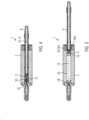
- Fig.1 shows a simplified schematic representation of individual components of various embodiments of a device 1 according to the invention for heating a foodstuff.
- the device 1 comprises a shaped tube 2.
- This can have a substantially cylindrical outer surface 3 and consist of an electrically non-conductive material, in particular completely or at least partially of a transparent material such as Plexiglas. It is also conceivable for the shaped tube 2 to be made of ceramic.
- the shaped tube 2 has an interior 4 which is delimited by an inner wall 5.
- a central section of the interior 4 is also cylindrical, but the interior 4 can also have any other cross-sectional shape.
- the interior 4 can have a diameter of, for example, 0.5 cm to 4 cm, but larger values are also conceivable.
- the interior 4 has a first opening 6 and a second opening 7 at its ends.
- a filling slide 8 is movable relative to the molding tube 2 and is intended to be inserted at least in sections into the interior 4 of the molding tube 2.
- an outer contour of the filling slide 8 is designed to be congruent to the cross section of the interior 4 of the shaped tube, but is dimensioned minimally smaller than the cross section of the interior 4 in order to seal the interior 4 at the first opening 6, but still allow it to be moved comparatively easily in the interior 4 .
- the outer contour 9 of the filling slide 8 can therefore be circular.
- the filling slide 8 is designed as a filling tube, ie with a line 10 in its interior, which is connected to a distal (in Fig. 1 : left) end is closed by a filling valve 11, designed here as a cone valve.
- the filling slide 8 is connected to a reservoir 13, in which the food 14 to be heated is held, via a schematically indicated, for example flexible, supply line 12.
- the food 14 can be pasty, for example a dough or meatloaf.
- the food 14 can be conveyed via the supply line to the filling slide 8 using a suitable conveying means such as a pump (not shown).
- the filling slide 8 has a first cap 15.
- the cap 15 has a concave surface 16 facing the interior 4.
- the opening of the filling valve 11 is located approximately in the center of the concave surface 16.
- the shaped tube 2 has a step 17.
- a second cap 18 with a cap body 19 can be inserted into the step 17.
- the cap body 19 comprises a flange 20 which can be inserted into the step 17.
- the second cap 18 has a concave Surface 21 which faces the interior 4 of the forming tube 2 or the concave surface 16 of the filling slide 8.
- a valve element 23 is movably mounted in the cap body 19, forming an air valve 22 on the second cap 18.
- the air valve 22 is designed as a cone valve, the opening of which is located approximately in the center of the concave surface 21 of the second cap 18.
- An air line 24 connects the air valve 22 to a vacuum source 25, for example a vacuum pump.
- a collet 26 is arranged in the molding tube 2.
- the collet 26 has two clamping jaws 26a, 26b, which can be moved relative to one another between an open position and a clamping position. In the open position, the distance between the clamping jaws 26a, 26b is large enough to allow the filling slide 8 to pass between them.
- the device 1 has a heating device 27, which can be connected to a controller 28 of the device 1.
- the heating device 27 serves to provide energy for heating a food 14 located in the molding tube 2.
- the heating device 27 can be configured in different ways.
- it can be a microwave generator that generates microwave radiation 29 and directs it onto the food 14 located in the mold tube 2.
- the heating device can be or comprise a liquid bath in which the shaped tube 2 is embedded to absorb heat, and/or the heating device 27 can comprise electrical resistance heating elements which rest on the shaped tube 2 or can be embedded in the wall of the shaped tube 2.
- the heating device 27 can have or include a power source and - as explained in detail below - be configured for ohmic heating of a food located in the molding tube 2.
- the first cap 15 and the second cap 18 are each designed as first and second electrodes, i.e. made of electrically conductive material.
- the concave surface 16, 21 of the first and second electrodes 15, 18 can be provided with a coating made of silver, for example.
- the collet chuck 26 and the filling slide 8 are preferably also electrically conductive or made of an electrically conductive material, and power lines 30 lead from the heating device 27 to the second cap 18 or to the collet chuck 26.
- the device has a substantially rod-shaped ejector 31.
- This comprises an annular cleaning lip 32 made of flexible material.
- the cleaning lip 32 is dimensioned such that it enables mechanical cleaning of the inner wall 5 of the interior 4 of the molding tube 2 when the ejector 31 is pushed from right to left through the interior 4.
- Fig.2 For the sake of clarity, some components of the device 1 are no longer shown.
- the device 1 is in a first state.
- the filling slide 8 is guided as far as possible into the interior 4 of the forming tube 2.
- the collet 26 is in its open position.
- the second cap 18 is inserted into the step 17 at the second opening 7 of the forming tube 2.
- the first and second caps 15, 18 touch each other or are only a minimal distance apart.
- the concave surfaces 16, 21 of the two caps 15, 18 form a cavity 33 between the two caps 15, 18.
- the air valve 22 is in its open position, in which the valve element 23 is retracted to the left. Via the air line 24, the vacuum source 25 ensures that the cavity 33 is evacuated via the air valve 22.
- the air pressure in the cavity 33 can be reduced to a value of less than 500 mbar, preferably less than 200 mbar or even less than 100 mbar.
- Fig.3 shows the device 1 in a second state.
- the air valve 22 has been closed by moving the valve element 23 of the air valve 22, which is designed as a cone valve, to the right into its valve seat. This completes the evacuation of the cavity 33.
- This offers the advantage that the subsequent filling of the cavity 33 with a food 14 is counteracted by considerably less resistance; in addition, the risk of air contained in the cavity 33 being stored in the food 14 when the cavity is filled and forming undesirable bubbles there is reduced, which could burst when the food is heated or cooked and destroy the food.
- Fig. 4 shows the device 1 in a third state, namely at the start of filling the cavity 33 with food.
- the filling valve 11 is open.
- the (usually pasty) food 14 is guided from the reservoir 13 to the filling slide 8 via the supply line 12.
- the food 14 is filled into the cavity 33 under a very high pressure of, for example, 10 bar to 25 bar.
- the internal pressure of the food 14 within the cavity 33 acts as a drive for the filling slide 8, which moves the filling slide 8 to the right, since the first cap 18 is fixed relative to the molding tube 2 more firmly than the filling slide 8.
- a (small) distance has already formed between the first cap 15 and the second cap 18.
- the cavity 33 is no longer empty from the start of filling with food 14; it can even (and usually will) be completely filled with the food 14.
- the term “ cavity” 33 is used in the sense of the invention even if the space between the two caps 15, 18 is completely or partially filled.
- Fig.5 shows the device 1 in a fourth state, in which the filling of the cavity 33 with the food 14 is completed.
- the entire space between the first cap 15 and the second cap 18 is filled with the food 14.
- the filling valve 11 on the filling slide 8 is shut off.
- the clamping jaws 26a, 26b of the collet 26 are brought into the closed position in which they clamp the filling slide 8 between them and thus fix it in place relative to the molding tube 2.
- the heating of the food 14 can be carried out.
- the heating device 27 serves to supply heat to the portion of the food 14 contained in the cavity 33. This can be done by means of heat conduction via the molding tube 2, by supplying electromagnetic radiation, for example microwave radiation 29, or by ohmic heating by applying an electrical voltage between the first and second caps 15, 18 designed as electrodes via the collet 26 and the electrically conductive filling slide 8. A current flows through the food 14, which is also electrically conductive, and is converted into heat by the electrical resistance of the food 14, which heats the food 14 at least locally, preferably completely and homogeneously.
- Heating is to be understood as meaning that the temperature of the food rises, for example by at least 5°C, whereby the food 14 can optionally also be cooked.
- the electrical voltage between the two caps 15, 18 designed as electrodes can be, for example, between 150V and 650V and can be applied for a duration of, for example, 5s to 45s.
- Fig.6 shows the device in a fifth state.
- the collet 26 has been brought into its open position.
- the filling slide 8 has been moved to the right and completely removed from the forming tube 2.
- the assembly with the second cap 18 has also been moved out of the step 17 and completely removed from the forming tube 2.
- the heated food 14 is still located in the interior 4 of the forming tube 2.
- the shape of the ends of the food 14 is predetermined by the concave surfaces 16, 21 of the caps 15, 18 or according to the shape of these surfaces 16, 21.
- Fig. 7 shows the device 1 in a sixth state.
- the forming tube 2 has been moved out of alignment 34 between the filling slide 8 and the second cap 18.
- the shaped tube 2 is mounted in a guide 35 and is offset along the guide relative to the filling slide 8.
- the shaped tube 2 (or a plurality of such shaped tubes 2) is arranged on a support 36, for example a rotatable drum 36, and was removed from alignment 34 by means of this.
- the mold slide 8 and the assembly with the second cap 18 are moved while the mold tube 2 remains stationary.
- the interior 4 of the shaped tube 2 is now aligned with the ejector 31. This is inserted through the first opening 6 into the interior of the shaped tube 2.
- the cleaning lip 32 strokes along the inner wall 5 of the interior 4 and in this way cleans the inner wall 5.
- the second opening 7 is free or open.
- Fig. 8 shows the device 1 in a seventh state. Based on the condition in Fig. 7 the ejector 31 has been moved so far through the interior 4 of the shaped tube 2 that the cleaning lip 32 has emerged from the second opening 7 of the shaped tube 2 at the distal end of the ejector 31. In this way, the heated (or cooked) food 14 is ejected or discharged from the forming tube 2. As a result, the device 1 or the method produces a heated, pre-cooked or even cooked food such as a sausage, for example a hot dog sausage, or a stick (pre-)baked from dough.
- the device 1 can be returned to the Fig.2 return to the first state shown; the cycle begins again.
- Fig. 9 shows a further exemplary embodiment of a device 1 according to the invention.
- the cap body 19 with the second cap 18 is here stationary relative to the shaped tube 2.
- the cap body 19 can be firmly mounted on the shaped tube 2 for this purpose.
- the air valve 22 can be connected via the air line 24 not only to a vacuum source 25, but also selectively to a compressed air source 37.
- element 37 can simply be a connection to the ambient air (normal pressure).
- a directional control valve 38 can be controlled by the controller 28 and ensures that the air valve 22 is always fluidly connected either to the vacuum source 25 or to the compressed air source 37.
- Fig. 9 shows the device 1 in a state in which the heating of the food 14 has been completed and the filling slide 8 has been completely removed from the forming tube 2.
- Fig. 10 shows the exemplary embodiment Fig. 9 in a second state. Starting from the in Fig. 9 In the state shown, the air valve 22 has been opened and connected via the directional control valve 38 to the compressed air source 37 or the ambient air under normal pressure. Air or compressed air is therefore passed into the cavity 33 via the air valve 22 in the second cap 18.
- the compressed air ensures that the heated food 14 is discharged or ejected to the right out of the forming tube 2.
- the second cap 18 or its cap body 19 serve as a counter bearing since they are connected in a stationary manner to the shaped tube 2.
- the compressed air can at the same time have a cleaning effect on the inner wall 5 of the interior 4.
- the device according to the invention and the method according to the invention can be modified in many ways.
- the compressed air source 37 and the directional control valve 38 can be dispensed with if ventilating the cavity 33 via the air valve 22 with normal pressure is sufficient to ventilate the food 14 - as in Fig. 11 shown - from the molding tube 2.
- the air valve 22 can, but does not have to, be formed in one piece with the cap body 19.
- it could also be arranged adjacent to the cap 18 in the wall of the molding tube 2.
- objects in the cavity 33 could also be sterilized.
Landscapes
- Life Sciences & Earth Sciences (AREA)
- Engineering & Computer Science (AREA)
- Polymers & Plastics (AREA)
- Chemical & Material Sciences (AREA)
- Food Science & Technology (AREA)
- Nutrition Science (AREA)
- Health & Medical Sciences (AREA)
- Wood Science & Technology (AREA)
- Zoology (AREA)
- General Preparation And Processing Of Foods (AREA)
- Processing Of Meat And Fish (AREA)
- Meat, Egg Or Seafood Products (AREA)
- Commercial Cooking Devices (AREA)
Priority Applications (8)
| Application Number | Priority Date | Filing Date | Title |
|---|---|---|---|
| EP21205404.3A EP4173492B1 (de) | 2021-10-28 | 2021-10-28 | Vorrichtung und verfahren zum erwärmen eines lebensmittels |
| DK21205404.3T DK4173492T3 (da) | 2021-10-28 | 2021-10-28 | Indretning og fremgangsmåde til opvarmning af et levnedsmiddel |
| ES21205404T ES2981126T3 (es) | 2021-10-28 | 2021-10-28 | Dispositivo y procedimiento para calentar un alimento |
| PL21205404.3T PL4173492T3 (pl) | 2021-10-28 | 2021-10-28 | Urządzenie i sposób podgrzewania żywności |
| US18/705,421 US20250008988A1 (en) | 2021-10-28 | 2022-10-07 | Device and method for heating food |
| PCT/EP2022/077897 WO2023072552A1 (de) | 2021-10-28 | 2022-10-07 | Vorrichtung und verfahren zum erwärmen eines lebensmittels |
| CN202280072186.4A CN118215405A (zh) | 2021-10-28 | 2022-10-07 | 用于加热食物的装置和方法 |
| JP2024524432A JP7760725B2 (ja) | 2021-10-28 | 2022-10-07 | 食品を加熱する装置及び方法 |
Applications Claiming Priority (1)
| Application Number | Priority Date | Filing Date | Title |
|---|---|---|---|
| EP21205404.3A EP4173492B1 (de) | 2021-10-28 | 2021-10-28 | Vorrichtung und verfahren zum erwärmen eines lebensmittels |
Publications (2)
| Publication Number | Publication Date |
|---|---|
| EP4173492A1 EP4173492A1 (de) | 2023-05-03 |
| EP4173492B1 true EP4173492B1 (de) | 2024-04-03 |
Family
ID=78770329
Family Applications (1)
| Application Number | Title | Priority Date | Filing Date |
|---|---|---|---|
| EP21205404.3A Active EP4173492B1 (de) | 2021-10-28 | 2021-10-28 | Vorrichtung und verfahren zum erwärmen eines lebensmittels |
Country Status (8)
| Country | Link |
|---|---|
| US (1) | US20250008988A1 (pl) |
| EP (1) | EP4173492B1 (pl) |
| JP (1) | JP7760725B2 (pl) |
| CN (1) | CN118215405A (pl) |
| DK (1) | DK4173492T3 (pl) |
| ES (1) | ES2981126T3 (pl) |
| PL (1) | PL4173492T3 (pl) |
| WO (1) | WO2023072552A1 (pl) |
Family Cites Families (10)
| Publication number | Priority date | Publication date | Assignee | Title |
|---|---|---|---|---|
| US3167000A (en) | 1959-04-16 | 1965-01-26 | Emhart Corp | Apparatus for manufacture of cooked meat products |
| ES473307A1 (es) * | 1977-09-14 | 1979-10-16 | Tivet Dev Ltd | Un metodo de preparar un producto carnico o similar a carne en molde |
| US4642847A (en) | 1985-10-08 | 1987-02-17 | Ross Henry M | Apparatus for forming sausage products |
| DE3939035A1 (de) * | 1989-11-25 | 1991-05-29 | Hauni Werke Koerber & Co Kg | Vorrichtung zum herstellen von wurstfoermigen lebensmittelprodukten |
| AU5492300A (en) | 1999-06-16 | 2001-01-02 | Penn State Research Foundation, The | Unit product continuous forming device |
| FR2795923A1 (fr) * | 1999-07-07 | 2001-01-12 | Act Ind | Procede de fabrication de saucisse sans peau, dispositif pour la mise en oeuvre de ce procede et saucisse fabriquee par ledit procede |
| US6740349B2 (en) | 1999-10-18 | 2004-05-25 | The Dial Corporation | Apparatus and method for forming casingless sausages |
| NL2009466C2 (nl) | 2012-09-14 | 2014-03-18 | Zwanenberg Food Group B V | Inrichting voor het pasteuriseren van een massa voedingswaar. |
| DE102014010166A1 (de) | 2013-08-16 | 2015-02-19 | Deutsches Institut Für Lebensmitteltechnik E.V. | Verfahren und Vorrichtung zur Behandlung eines Lebensmittels mittels Erhitzung |
| DE102021120881A1 (de) | 2020-08-12 | 2022-02-17 | Fritz Kortschack | Spezialelektrodenanordnung zur gezielten Ohm'schen Erhitzung unterschiedlicher, elektrisch leitfähige oder elektrisch leitfähige Bestandteile enthaltende Güter oder Strukturen |
-
2021
- 2021-10-28 EP EP21205404.3A patent/EP4173492B1/de active Active
- 2021-10-28 PL PL21205404.3T patent/PL4173492T3/pl unknown
- 2021-10-28 DK DK21205404.3T patent/DK4173492T3/da active
- 2021-10-28 ES ES21205404T patent/ES2981126T3/es active Active
-
2022
- 2022-10-07 CN CN202280072186.4A patent/CN118215405A/zh active Pending
- 2022-10-07 US US18/705,421 patent/US20250008988A1/en active Pending
- 2022-10-07 WO PCT/EP2022/077897 patent/WO2023072552A1/de not_active Ceased
- 2022-10-07 JP JP2024524432A patent/JP7760725B2/ja active Active
Also Published As
| Publication number | Publication date |
|---|---|
| JP2024540999A (ja) | 2024-11-06 |
| US20250008988A1 (en) | 2025-01-09 |
| DK4173492T3 (da) | 2024-05-27 |
| CN118215405A (zh) | 2024-06-18 |
| ES2981126T3 (es) | 2024-10-07 |
| WO2023072552A1 (de) | 2023-05-04 |
| EP4173492A1 (de) | 2023-05-03 |
| PL4173492T3 (pl) | 2024-08-19 |
| JP7760725B2 (ja) | 2025-10-27 |
Similar Documents
| Publication | Publication Date | Title |
|---|---|---|
| EP1981378B1 (de) | Dampffunktion am ende eines brühvorgangs | |
| EP3367852B1 (de) | Vorrichtung und verfahren zum aufbereiten von lebensmitteln | |
| DE2306927C3 (de) | Druckkochvorrichtung | |
| DE102013114799A1 (de) | Vorrichtung und Verfahren zur Herstellung eines Partikelschaumstoffteils | |
| EP0384278A2 (de) | Verfahren und Vorrichtung zum Auftragen von flüssigen, pastösen oder plastischen Substanzen auf ein Substrat | |
| EP3190937A1 (de) | GARAUFSATZ FÜR EIN AUFHEIZBARES GEFÄß EINER KÜCHENMASCHINE | |
| DE2541374A1 (de) | Garmachverfahren und -vorrichtung | |
| DE60117267T2 (de) | Verfahren und vorrichtung zur thermischen behandelung ungeschaelter eier | |
| EP4173492B1 (de) | Vorrichtung und verfahren zum erwärmen eines lebensmittels | |
| DE202017105946U1 (de) | Vorrichtung zum automatisierten Erhitzen und/oder Garen von Lebensmitteln | |
| EP2918197A1 (de) | Siebträgeranordnung, Siebträger-Kaffeemaschine und Ableiteinsatz | |
| EP3011246A1 (de) | Verfahren und injektor zum einleiten eines dampfförmigen wärmeträgers in ein flüssiges produkt | |
| DE102015221005A1 (de) | Anlage und Verfahren zum Bereistellen von Dampf sowie Vorrichtung umfassend eine derartige Anlage | |
| EP0303260B1 (de) | Vorsatzgerät für einen Wurstfüller | |
| EP3816305A1 (de) | Verfahren und vorrichtung zur thermischen behandlung eines rohrförmigen metallischen bauteils | |
| DE2731137B2 (de) | Dampfbeheiztes Koch- und Sterilisationsgerät | |
| DE3911544A1 (de) | Verfahren und vorrichtung zum stumpfschweissen von zwei kunststoff-rohrabschnitten oder kunststoff-formstuecken | |
| DE102016106874B4 (de) | Backvorrichtung und Verfahren zum mehrflächigen Backen | |
| DE912329C (de) | Homogenisiervorrichtung fuer Fluessigkeiten | |
| DE4141976C2 (de) | Verfahren und Vorrichtung zum Keimfreimachen von schüttfähigen Stoffen | |
| EP3118528B1 (de) | Garsystem zum garen und aromatisieren von gargut | |
| DE3939035A1 (de) | Vorrichtung zum herstellen von wurstfoermigen lebensmittelprodukten | |
| DE1068616B (de) | Vorrichtung zum Dosieren, Formen und Verpacken von plastischen Nahrungs- und Genußmitteln wie Butter, Margarine, Speiseeis u. dgl | |
| DE10331863B3 (de) | Vorrichtung zur Herstellung von dental medizinischen Präzisionsformteilen aus polymerisierbarem Kunststoff | |
| DE102023127099A1 (de) | Kolbenkaffeemaschine mit einer Brüheinheit, und Verfahren zum Temperieren einer Brühbuchse einer solchen Brüheinheit |
Legal Events
| Date | Code | Title | Description |
|---|---|---|---|
| PUAI | Public reference made under article 153(3) epc to a published international application that has entered the european phase |
Free format text: ORIGINAL CODE: 0009012 |
|
| STAA | Information on the status of an ep patent application or granted ep patent |
Free format text: STATUS: REQUEST FOR EXAMINATION WAS MADE |
|
| 17P | Request for examination filed |
Effective date: 20220608 |
|
| AK | Designated contracting states |
Kind code of ref document: A1 Designated state(s): AL AT BE BG CH CY CZ DE DK EE ES FI FR GB GR HR HU IE IS IT LI LT LU LV MC MK MT NL NO PL PT RO RS SE SI SK SM TR |
|
| P01 | Opt-out of the competence of the unified patent court (upc) registered |
Effective date: 20230523 |
|
| GRAP | Despatch of communication of intention to grant a patent |
Free format text: ORIGINAL CODE: EPIDOSNIGR1 |
|
| STAA | Information on the status of an ep patent application or granted ep patent |
Free format text: STATUS: GRANT OF PATENT IS INTENDED |
|
| INTG | Intention to grant announced |
Effective date: 20231027 |
|
| GRAS | Grant fee paid |
Free format text: ORIGINAL CODE: EPIDOSNIGR3 |
|
| GRAA | (expected) grant |
Free format text: ORIGINAL CODE: 0009210 |
|
| STAA | Information on the status of an ep patent application or granted ep patent |
Free format text: STATUS: THE PATENT HAS BEEN GRANTED |
|
| AK | Designated contracting states |
Kind code of ref document: B1 Designated state(s): AL AT BE BG CH CY CZ DE DK EE ES FI FR GB GR HR HU IE IS IT LI LT LU LV MC MK MT NL NO PL PT RO RS SE SI SK SM TR |
|
| REG | Reference to a national code |
Ref country code: CH Ref legal event code: EP |
|
| REG | Reference to a national code |
Ref country code: IE Ref legal event code: FG4D Free format text: LANGUAGE OF EP DOCUMENT: GERMAN |
|
| REG | Reference to a national code |
Ref country code: DE Ref legal event code: R096 Ref document number: 502021003191 Country of ref document: DE |
|
| REG | Reference to a national code |
Ref country code: DK Ref legal event code: T3 Effective date: 20240524 |
|
| REG | Reference to a national code |
Ref country code: NL Ref legal event code: FP |
|
| REG | Reference to a national code |
Ref country code: LT Ref legal event code: MG9D |
|
| PG25 | Lapsed in a contracting state [announced via postgrant information from national office to epo] |
Ref country code: IS Free format text: LAPSE BECAUSE OF FAILURE TO SUBMIT A TRANSLATION OF THE DESCRIPTION OR TO PAY THE FEE WITHIN THE PRESCRIBED TIME-LIMIT Effective date: 20240803 |
|
| REG | Reference to a national code |
Ref country code: ES Ref legal event code: FG2A Ref document number: 2981126 Country of ref document: ES Kind code of ref document: T3 Effective date: 20241007 |
|
| PG25 | Lapsed in a contracting state [announced via postgrant information from national office to epo] |
Ref country code: BG Free format text: LAPSE BECAUSE OF FAILURE TO SUBMIT A TRANSLATION OF THE DESCRIPTION OR TO PAY THE FEE WITHIN THE PRESCRIBED TIME-LIMIT Effective date: 20240403 |
|
| PG25 | Lapsed in a contracting state [announced via postgrant information from national office to epo] |
Ref country code: HR Free format text: LAPSE BECAUSE OF FAILURE TO SUBMIT A TRANSLATION OF THE DESCRIPTION OR TO PAY THE FEE WITHIN THE PRESCRIBED TIME-LIMIT Effective date: 20240403 Ref country code: FI Free format text: LAPSE BECAUSE OF FAILURE TO SUBMIT A TRANSLATION OF THE DESCRIPTION OR TO PAY THE FEE WITHIN THE PRESCRIBED TIME-LIMIT Effective date: 20240403 |
|
| PG25 | Lapsed in a contracting state [announced via postgrant information from national office to epo] |
Ref country code: GR Free format text: LAPSE BECAUSE OF FAILURE TO SUBMIT A TRANSLATION OF THE DESCRIPTION OR TO PAY THE FEE WITHIN THE PRESCRIBED TIME-LIMIT Effective date: 20240704 |
|
| PG25 | Lapsed in a contracting state [announced via postgrant information from national office to epo] |
Ref country code: PT Free format text: LAPSE BECAUSE OF FAILURE TO SUBMIT A TRANSLATION OF THE DESCRIPTION OR TO PAY THE FEE WITHIN THE PRESCRIBED TIME-LIMIT Effective date: 20240805 |
|
| PG25 | Lapsed in a contracting state [announced via postgrant information from national office to epo] |
Ref country code: CZ Free format text: LAPSE BECAUSE OF FAILURE TO SUBMIT A TRANSLATION OF THE DESCRIPTION OR TO PAY THE FEE WITHIN THE PRESCRIBED TIME-LIMIT Effective date: 20240403 |
|
| PG25 | Lapsed in a contracting state [announced via postgrant information from national office to epo] |
Ref country code: LV Free format text: LAPSE BECAUSE OF FAILURE TO SUBMIT A TRANSLATION OF THE DESCRIPTION OR TO PAY THE FEE WITHIN THE PRESCRIBED TIME-LIMIT Effective date: 20240403 |
|
| PG25 | Lapsed in a contracting state [announced via postgrant information from national office to epo] |
Ref country code: PT Free format text: LAPSE BECAUSE OF FAILURE TO SUBMIT A TRANSLATION OF THE DESCRIPTION OR TO PAY THE FEE WITHIN THE PRESCRIBED TIME-LIMIT Effective date: 20240805 Ref country code: NO Free format text: LAPSE BECAUSE OF FAILURE TO SUBMIT A TRANSLATION OF THE DESCRIPTION OR TO PAY THE FEE WITHIN THE PRESCRIBED TIME-LIMIT Effective date: 20240703 Ref country code: LV Free format text: LAPSE BECAUSE OF FAILURE TO SUBMIT A TRANSLATION OF THE DESCRIPTION OR TO PAY THE FEE WITHIN THE PRESCRIBED TIME-LIMIT Effective date: 20240403 Ref country code: IS Free format text: LAPSE BECAUSE OF FAILURE TO SUBMIT A TRANSLATION OF THE DESCRIPTION OR TO PAY THE FEE WITHIN THE PRESCRIBED TIME-LIMIT Effective date: 20240803 Ref country code: HR Free format text: LAPSE BECAUSE OF FAILURE TO SUBMIT A TRANSLATION OF THE DESCRIPTION OR TO PAY THE FEE WITHIN THE PRESCRIBED TIME-LIMIT Effective date: 20240403 Ref country code: GR Free format text: LAPSE BECAUSE OF FAILURE TO SUBMIT A TRANSLATION OF THE DESCRIPTION OR TO PAY THE FEE WITHIN THE PRESCRIBED TIME-LIMIT Effective date: 20240704 Ref country code: FI Free format text: LAPSE BECAUSE OF FAILURE TO SUBMIT A TRANSLATION OF THE DESCRIPTION OR TO PAY THE FEE WITHIN THE PRESCRIBED TIME-LIMIT Effective date: 20240403 Ref country code: CZ Free format text: LAPSE BECAUSE OF FAILURE TO SUBMIT A TRANSLATION OF THE DESCRIPTION OR TO PAY THE FEE WITHIN THE PRESCRIBED TIME-LIMIT Effective date: 20240403 Ref country code: BG Free format text: LAPSE BECAUSE OF FAILURE TO SUBMIT A TRANSLATION OF THE DESCRIPTION OR TO PAY THE FEE WITHIN THE PRESCRIBED TIME-LIMIT Effective date: 20240403 Ref country code: RS Free format text: LAPSE BECAUSE OF FAILURE TO SUBMIT A TRANSLATION OF THE DESCRIPTION OR TO PAY THE FEE WITHIN THE PRESCRIBED TIME-LIMIT Effective date: 20240703 |
|
| REG | Reference to a national code |
Ref country code: DE Ref legal event code: R097 Ref document number: 502021003191 Country of ref document: DE |
|
| PGFP | Annual fee paid to national office [announced via postgrant information from national office to epo] |
Ref country code: DK Payment date: 20241023 Year of fee payment: 4 |
|
| PGFP | Annual fee paid to national office [announced via postgrant information from national office to epo] |
Ref country code: PL Payment date: 20241003 Year of fee payment: 4 |
|
| PG25 | Lapsed in a contracting state [announced via postgrant information from national office to epo] |
Ref country code: EE Free format text: LAPSE BECAUSE OF FAILURE TO SUBMIT A TRANSLATION OF THE DESCRIPTION OR TO PAY THE FEE WITHIN THE PRESCRIBED TIME-LIMIT Effective date: 20240403 |
|
| PG25 | Lapsed in a contracting state [announced via postgrant information from national office to epo] |
Ref country code: RO Free format text: LAPSE BECAUSE OF FAILURE TO SUBMIT A TRANSLATION OF THE DESCRIPTION OR TO PAY THE FEE WITHIN THE PRESCRIBED TIME-LIMIT Effective date: 20240403 Ref country code: SK Free format text: LAPSE BECAUSE OF FAILURE TO SUBMIT A TRANSLATION OF THE DESCRIPTION OR TO PAY THE FEE WITHIN THE PRESCRIBED TIME-LIMIT Effective date: 20240403 |
|
| PG25 | Lapsed in a contracting state [announced via postgrant information from national office to epo] |
Ref country code: SM Free format text: LAPSE BECAUSE OF FAILURE TO SUBMIT A TRANSLATION OF THE DESCRIPTION OR TO PAY THE FEE WITHIN THE PRESCRIBED TIME-LIMIT Effective date: 20240403 |
|
| PG25 | Lapsed in a contracting state [announced via postgrant information from national office to epo] |
Ref country code: SM Free format text: LAPSE BECAUSE OF FAILURE TO SUBMIT A TRANSLATION OF THE DESCRIPTION OR TO PAY THE FEE WITHIN THE PRESCRIBED TIME-LIMIT Effective date: 20240403 Ref country code: SK Free format text: LAPSE BECAUSE OF FAILURE TO SUBMIT A TRANSLATION OF THE DESCRIPTION OR TO PAY THE FEE WITHIN THE PRESCRIBED TIME-LIMIT Effective date: 20240403 Ref country code: RO Free format text: LAPSE BECAUSE OF FAILURE TO SUBMIT A TRANSLATION OF THE DESCRIPTION OR TO PAY THE FEE WITHIN THE PRESCRIBED TIME-LIMIT Effective date: 20240403 Ref country code: EE Free format text: LAPSE BECAUSE OF FAILURE TO SUBMIT A TRANSLATION OF THE DESCRIPTION OR TO PAY THE FEE WITHIN THE PRESCRIBED TIME-LIMIT Effective date: 20240403 |
|
| PLBE | No opposition filed within time limit |
Free format text: ORIGINAL CODE: 0009261 |
|
| STAA | Information on the status of an ep patent application or granted ep patent |
Free format text: STATUS: NO OPPOSITION FILED WITHIN TIME LIMIT |
|
| 26N | No opposition filed |
Effective date: 20250106 |
|
| PG25 | Lapsed in a contracting state [announced via postgrant information from national office to epo] |
Ref country code: SI Free format text: LAPSE BECAUSE OF FAILURE TO SUBMIT A TRANSLATION OF THE DESCRIPTION OR TO PAY THE FEE WITHIN THE PRESCRIBED TIME-LIMIT Effective date: 20240403 |
|
| REG | Reference to a national code |
Ref country code: CH Ref legal event code: PL |
|
| PG25 | Lapsed in a contracting state [announced via postgrant information from national office to epo] |
Ref country code: MC Free format text: LAPSE BECAUSE OF FAILURE TO SUBMIT A TRANSLATION OF THE DESCRIPTION OR TO PAY THE FEE WITHIN THE PRESCRIBED TIME-LIMIT Effective date: 20240403 |
|
| PG25 | Lapsed in a contracting state [announced via postgrant information from national office to epo] |
Ref country code: LU Free format text: LAPSE BECAUSE OF NON-PAYMENT OF DUE FEES Effective date: 20241028 Ref country code: BE Free format text: LAPSE BECAUSE OF NON-PAYMENT OF DUE FEES Effective date: 20241031 |
|
| PG25 | Lapsed in a contracting state [announced via postgrant information from national office to epo] |
Ref country code: CH Free format text: LAPSE BECAUSE OF NON-PAYMENT OF DUE FEES Effective date: 20241031 |
|
| REG | Reference to a national code |
Ref country code: BE Ref legal event code: MM Effective date: 20241031 |
|
| PG25 | Lapsed in a contracting state [announced via postgrant information from national office to epo] |
Ref country code: SE Free format text: LAPSE BECAUSE OF FAILURE TO SUBMIT A TRANSLATION OF THE DESCRIPTION OR TO PAY THE FEE WITHIN THE PRESCRIBED TIME-LIMIT Effective date: 20240403 |
|
| PG25 | Lapsed in a contracting state [announced via postgrant information from national office to epo] |
Ref country code: IE Free format text: LAPSE BECAUSE OF NON-PAYMENT OF DUE FEES Effective date: 20241028 |
|
| PGFP | Annual fee paid to national office [announced via postgrant information from national office to epo] |
Ref country code: AT Payment date: 20260113 Year of fee payment: 5 |
|
| PG25 | Lapsed in a contracting state [announced via postgrant information from national office to epo] |
Ref country code: IT Free format text: LAPSE BECAUSE OF NON-PAYMENT OF DUE FEES Effective date: 20241028 |
|
| PGFP | Annual fee paid to national office [announced via postgrant information from national office to epo] |
Ref country code: NL Payment date: 20260109 Year of fee payment: 5 |
|
| PG25 | Lapsed in a contracting state [announced via postgrant information from national office to epo] |
Ref country code: HU Free format text: LAPSE BECAUSE OF FAILURE TO SUBMIT A TRANSLATION OF THE DESCRIPTION OR TO PAY THE FEE WITHIN THE PRESCRIBED TIME-LIMIT; INVALID AB INITIO Effective date: 20211028 |
|
| PG25 | Lapsed in a contracting state [announced via postgrant information from national office to epo] |
Ref country code: CY Free format text: LAPSE BECAUSE OF FAILURE TO SUBMIT A TRANSLATION OF THE DESCRIPTION OR TO PAY THE FEE WITHIN THE PRESCRIBED TIME-LIMIT; INVALID AB INITIO Effective date: 20211028 |
|
| PGFP | Annual fee paid to national office [announced via postgrant information from national office to epo] |
Ref country code: GB Payment date: 20260109 Year of fee payment: 5 |
|
| PGFP | Annual fee paid to national office [announced via postgrant information from national office to epo] |
Ref country code: ES Payment date: 20260113 Year of fee payment: 5 |
|
| PGFP | Annual fee paid to national office [announced via postgrant information from national office to epo] |
Ref country code: DE Payment date: 20260108 Year of fee payment: 5 |
|
| PG25 | Lapsed in a contracting state [announced via postgrant information from national office to epo] |
Ref country code: IT Free format text: LAPSE BECAUSE OF NON-PAYMENT OF DUE FEES Effective date: 20241028 |
|
| PGFP | Annual fee paid to national office [announced via postgrant information from national office to epo] |
Ref country code: IT Payment date: 20260128 Year of fee payment: 5 |
|
| PGRI | Patent reinstated in contracting state [announced from national office to epo] |
Ref country code: IT Effective date: 20241031 |
|
| PGFP | Annual fee paid to national office [announced via postgrant information from national office to epo] |
Ref country code: FR Payment date: 20260109 Year of fee payment: 5 |