EP4173695A1 - Système de filtration de membrane - Google Patents
Système de filtration de membrane Download PDFInfo
- Publication number
- EP4173695A1 EP4173695A1 EP21205628.7A EP21205628A EP4173695A1 EP 4173695 A1 EP4173695 A1 EP 4173695A1 EP 21205628 A EP21205628 A EP 21205628A EP 4173695 A1 EP4173695 A1 EP 4173695A1
- Authority
- EP
- European Patent Office
- Prior art keywords
- concentrate
- filtration system
- pump
- control device
- membrane filtration
- Prior art date
- Legal status (The legal status is an assumption and is not a legal conclusion. Google has not performed a legal analysis and makes no representation as to the accuracy of the status listed.)
- Pending
Links
- 238000005374 membrane filtration Methods 0.000 title claims abstract description 59
- 239000012141 concentrate Substances 0.000 claims abstract description 168
- 239000012466 permeate Substances 0.000 claims abstract description 38
- 239000012528 membrane Substances 0.000 claims abstract description 29
- 238000011010 flushing procedure Methods 0.000 claims description 58
- 238000011084 recovery Methods 0.000 claims description 31
- 238000001914 filtration Methods 0.000 claims description 24
- 239000007788 liquid Substances 0.000 claims description 10
- 238000006073 displacement reaction Methods 0.000 claims description 9
- 238000001223 reverse osmosis Methods 0.000 claims description 4
- 238000001728 nano-filtration Methods 0.000 claims description 3
- 108091006146 Channels Proteins 0.000 description 25
- 238000010586 diagram Methods 0.000 description 10
- 239000012267 brine Substances 0.000 description 8
- HPALAKNZSZLMCH-UHFFFAOYSA-M sodium;chloride;hydrate Chemical compound O.[Na+].[Cl-] HPALAKNZSZLMCH-UHFFFAOYSA-M 0.000 description 8
- 238000004519 manufacturing process Methods 0.000 description 7
- 230000001276 controlling effect Effects 0.000 description 6
- 150000003839 salts Chemical class 0.000 description 6
- 230000001186 cumulative effect Effects 0.000 description 4
- XLYOFNOQVPJJNP-UHFFFAOYSA-N water Substances O XLYOFNOQVPJJNP-UHFFFAOYSA-N 0.000 description 4
- 230000009286 beneficial effect Effects 0.000 description 3
- 238000004891 communication Methods 0.000 description 3
- 238000012544 monitoring process Methods 0.000 description 3
- 206010016825 Flushing Diseases 0.000 description 2
- 238000009825 accumulation Methods 0.000 description 2
- 238000013461 design Methods 0.000 description 2
- 239000002245 particle Substances 0.000 description 2
- 230000002829 reductive effect Effects 0.000 description 2
- 230000000717 retained effect Effects 0.000 description 2
- 108090000862 Ion Channels Proteins 0.000 description 1
- 102000004310 Ion Channels Human genes 0.000 description 1
- 230000015572 biosynthetic process Effects 0.000 description 1
- 238000011968 cross flow microfiltration Methods 0.000 description 1
- 230000007423 decrease Effects 0.000 description 1
- 230000003247 decreasing effect Effects 0.000 description 1
- 230000001419 dependent effect Effects 0.000 description 1
- 238000005265 energy consumption Methods 0.000 description 1
- 239000012530 fluid Substances 0.000 description 1
- 230000000977 initiatory effect Effects 0.000 description 1
- 238000009434 installation Methods 0.000 description 1
- 230000000670 limiting effect Effects 0.000 description 1
- 238000012423 maintenance Methods 0.000 description 1
- 238000005259 measurement Methods 0.000 description 1
- 238000000034 method Methods 0.000 description 1
- 238000012806 monitoring device Methods 0.000 description 1
- 230000001105 regulatory effect Effects 0.000 description 1
- 239000012465 retentate Substances 0.000 description 1
- 238000000108 ultra-filtration Methods 0.000 description 1
Images


Classifications
-
- B—PERFORMING OPERATIONS; TRANSPORTING
- B01—PHYSICAL OR CHEMICAL PROCESSES OR APPARATUS IN GENERAL
- B01D—SEPARATION
- B01D61/00—Processes of separation using semi-permeable membranes, e.g. dialysis, osmosis or ultrafiltration; Apparatus, accessories or auxiliary operations specially adapted therefor
- B01D61/02—Reverse osmosis; Hyperfiltration ; Nanofiltration
- B01D61/12—Controlling or regulating
-
- B—PERFORMING OPERATIONS; TRANSPORTING
- B01—PHYSICAL OR CHEMICAL PROCESSES OR APPARATUS IN GENERAL
- B01D—SEPARATION
- B01D2311/00—Details relating to membrane separation process operations and control
- B01D2311/08—Specific process operations in the concentrate stream
-
- B—PERFORMING OPERATIONS; TRANSPORTING
- B01—PHYSICAL OR CHEMICAL PROCESSES OR APPARATUS IN GENERAL
- B01D—SEPARATION
- B01D2311/00—Details relating to membrane separation process operations and control
- B01D2311/16—Flow or flux control
- B01D2311/165—Cross-flow velocity control
-
- B—PERFORMING OPERATIONS; TRANSPORTING
- B01—PHYSICAL OR CHEMICAL PROCESSES OR APPARATUS IN GENERAL
- B01D—SEPARATION
- B01D2311/00—Details relating to membrane separation process operations and control
- B01D2311/24—Quality control
- B01D2311/246—Concentration control
-
- B—PERFORMING OPERATIONS; TRANSPORTING
- B01—PHYSICAL OR CHEMICAL PROCESSES OR APPARATUS IN GENERAL
- B01D—SEPARATION
- B01D2311/00—Details relating to membrane separation process operations and control
- B01D2311/25—Recirculation, recycling or bypass, e.g. recirculation of concentrate into the feed
-
- B—PERFORMING OPERATIONS; TRANSPORTING
- B01—PHYSICAL OR CHEMICAL PROCESSES OR APPARATUS IN GENERAL
- B01D—SEPARATION
- B01D2311/00—Details relating to membrane separation process operations and control
- B01D2311/25—Recirculation, recycling or bypass, e.g. recirculation of concentrate into the feed
- B01D2311/252—Recirculation of concentrate
- B01D2311/2523—Recirculation of concentrate to feed side
-
- B—PERFORMING OPERATIONS; TRANSPORTING
- B01—PHYSICAL OR CHEMICAL PROCESSES OR APPARATUS IN GENERAL
- B01D—SEPARATION
- B01D2313/00—Details relating to membrane modules or apparatus
- B01D2313/12—Specific discharge elements
-
- B—PERFORMING OPERATIONS; TRANSPORTING
- B01—PHYSICAL OR CHEMICAL PROCESSES OR APPARATUS IN GENERAL
- B01D—SEPARATION
- B01D2313/00—Details relating to membrane modules or apparatus
- B01D2313/16—Specific vents
-
- B—PERFORMING OPERATIONS; TRANSPORTING
- B01—PHYSICAL OR CHEMICAL PROCESSES OR APPARATUS IN GENERAL
- B01D—SEPARATION
- B01D2313/00—Details relating to membrane modules or apparatus
- B01D2313/19—Specific flow restrictors
-
- B—PERFORMING OPERATIONS; TRANSPORTING
- B01—PHYSICAL OR CHEMICAL PROCESSES OR APPARATUS IN GENERAL
- B01D—SEPARATION
- B01D2313/00—Details relating to membrane modules or apparatus
- B01D2313/24—Specific pressurizing or depressurizing means
- B01D2313/243—Pumps
-
- B—PERFORMING OPERATIONS; TRANSPORTING
- B01—PHYSICAL OR CHEMICAL PROCESSES OR APPARATUS IN GENERAL
- B01D—SEPARATION
- B01D2315/00—Details relating to the membrane module operation
- B01D2315/10—Cross-flow filtration
-
- Y—GENERAL TAGGING OF NEW TECHNOLOGICAL DEVELOPMENTS; GENERAL TAGGING OF CROSS-SECTIONAL TECHNOLOGIES SPANNING OVER SEVERAL SECTIONS OF THE IPC; TECHNICAL SUBJECTS COVERED BY FORMER USPC CROSS-REFERENCE ART COLLECTIONS [XRACs] AND DIGESTS
- Y02—TECHNOLOGIES OR APPLICATIONS FOR MITIGATION OR ADAPTATION AGAINST CLIMATE CHANGE
- Y02A—TECHNOLOGIES FOR ADAPTATION TO CLIMATE CHANGE
- Y02A20/00—Water conservation; Efficient water supply; Efficient water use
- Y02A20/124—Water desalination
- Y02A20/131—Reverse-osmosis
Definitions
- the invention refers to a membrane filtration system and a retrofit concentrate draining device configured for use in a membrane filtration system.
- Known membrane filtration systems like nano filtration systems or reverse osmosis filtration systems, for example, often comprise a recirculation or crossflow allowing a recovery of the concentrate. It is known to have a draining valve in said crossflow line to partly discharge the concentrate during operation. In some applications, it is known to periodically flush the membrane feed a concentrate channel by opening a respective valve. During the operation at high recoveries, the concentration or salinity in the concentrate increases. The changing concentration has a great influence on the formation or accumulation of organic and inorganic foulness in the membrane filters and the energy consumption of the overall system.
- the membrane filtration system comprises at least one membrane with an inlet, and a concentrate outlet on one side of this membrane. Furthermore, the filtration system comprises a permeate outlet on the opposite side of the at least one membrane. Thus, a part of the liquid entering the inlet passes the at least one membrane and leaves through the permeate outlet. Another part of the liquid entering the inlet is retained by the membrane and eventually discharged as a concentrate through a concentrate outlet. For example, salts in the liquid are retained by the membrane so that the concentrate is a brine having an increased concentration of salts.
- the system may further comprise a recirculation channel connecting the concentrate outlet and the inlet such that the concentrate can be circulated on the first side of the membrane, defining the inlet or concentrate side of the membrane. During this circulation, the concentration or salinity of the concentrate increases due to the liquid passing the membrane.
- the membrane filtration system comprises an active concentrate draining device for removing a defined amount or flow of concentrate from the system, i. e. to precisely discharge a defined amount of concentrate.
- the concentrate draining device comprises at least one pump and is connected to said concentrate outlet.
- the pump actively drains out a part of the concentrate from the crossflow channel.
- the pump allows a controlled concentrate output allowing to precisely adjust the concentrate output and the recovery, in particular a recovery rate during the filtration process. This allows to control the entire filtration process more precisely, for example, to increase the efficiency and/or to reduce to amount of energy required for filtration.
- the pump of the concentrate draining device can be operated to provide a continuous or a quasi continuous concentrate output of the filtration system.
- This allows a continuous concentrate output and a continuous permeate output of the system at the same time, allowing a production without interruption.
- the use of a pump allows to more precisely control the amount of concentrate discharge, as for example possible with a valve or regulating valve.
- the concentrate draining device according to the invention using a pump may be used in a filtration system without a recirculation of concentrate as well as in a membrane filtration system having a recirculation channel connecting the concentrate outlet and the inlet allowing a recirculation of a concentrate.
- said concentrate draining device comprises a flushing valve, which preferably is placed in parallel to the at least one pump of the concentrate draining device, i.e. in a conduit parallel to the at least one pump.
- the flushing valve allows to flush the membrane filtration system, i. e. to preferably exchange the entire amount of liquid contained in the filtration system.
- the flushing valve may have a greater cross section than the at least one pump, i.e. the valve may allow a higher flow than the at least one pump or several pumps. This allows to have a greater flow during flushing than during concentrate discharge provided by the pump or pumps.
- a flushing is initiated in case that the concentration or salinity in the crossflow reaches or exceeds a predefined threshold.
- the concentration or salinity may continuously increase requiring a flushing after a certain period of operation, i. e. from time to time.
- a certain period of operation i. e. from time to time.
- the flushing valve is controlled by the control device of the concentrate draining device.
- control device may activate the flushing valve to initiate the flushing of the filtration system, for example on basis of a sensor signal or after a predefined period of operation.
- the concentrate concentration increases from a concentration closed to feed water concentration at the start to a highest steady state concentration. This steady state concentration depends on the permeate flow to feed flow ratio or water recovery. Forward flushing preferably is performed before the concentration reaches steady state, thereby reducing the concentration back down to initial level.
- the membrane filtration system is operated at repeating cycles of filtration and flushing with the concentrate concentration changing within each cycle.
- the at least one pump is a positive displacement pump.
- a positive displacement pump may be a metering pump allowing to provide a precise fluid flow and exact control of the amount of concentrate output from the filtration system.
- the positive displacement pump for example, may be a membrane or piston pump.
- Such a reciprocating pump like a membrane or piston pump may for example be controlled in stroke speed and/or stroke length to adjust the flow of concentrate output.
- the concentrate draining device comprises at least one pressure reduction valve, which is placed in front of the at least one pump of the concentrate draining device.
- the pressure reduction valve or valves ensure a desired inlet pressure for the at least one pump, in particular the positive displacement pump.
- a pressure reduction valve or valves ensure a maximum inlet pressure for the at least one pump and in particular reduces the pressure to the maximum inlet pressure or below a maximum inlet pressure. This is in particular of importance with increasing pressure in the crossflow channel occurring from increasing salinity during the operation.
- the concentrate draining device comprises a control device configured to control the amount of concentrate which is drawn off by the at least one pump.
- the control device preferably controls the pump, in particular controls the flow produced by the pump, for example by control of the stroke length and/or stroke speed of a reciprocating positive displacement pump.
- the control device may be an electronic device, preferably comprising a microcontroller executing a control software, which configured to provide the desired control functionality.
- the amount of concentrate, which is drawn off may be predefined in the control device or input by an operator using suitable input means of the control device or being connected to the control device.
- the control device is configured such that the amount of concentrate drawn off is controlled to achieve a target recovery rate, which target recovery rate preferably is in the range between 50% and 99,9%, i.e. near 100%.
- the recovery rate is defined as the ratio of feed or inlet flow and the permeate output or flow produced in a cycle.
- the cycle is defined as a filtration cycle between two flushings of the inlet and concentration channel.
- the recovery rate may be defined as a net recovery rate considering the loss during flushing or the recovery rate without considering this loss.
- the recovery rate may be monitored, preferably continuously monitored in the system by use of suitable sensors.
- At least one flow sensor is arranged in the permeate outlet and/or in said inlet, which at least one flow sensor is connected to the control device, i.e. communicating with the control device, such that the control device receives sensor data representing the flow.
- the control device preferably there are provided at least two flow sensors, one in the inlet and one in the permeate outlet, or one in the inlet and one in the concentrate outlet. This allows a direct measurement or calculation of the permeate flow.
- the control device preferably is configured such that it controls a concentrate draining device, in particular the at least one pump on basis of the output signal of the at least one flow sensor, preferably several flow sensors, for example one flow sensor in the inlet and one flow sensor in the permeate outlet.
- the recovery rate as defined above, can be calculated, and the recovery rate can be controlled to achieve a target recovery rate as explained above.
- the concentrate outlet flow is known by the control device, since it is set by the control device and provided by respective control of the at least one pump in the concentrate draining device.
- a flow sensor in the recirculation channel may directly detect the crossflow or circulating flow of concentrate. All the required sensors are connected to, i.e. communicating with the control device, so that the control device can carry out a control of the pump on basis of the received sensor data.
- the connection for communication of the sensors and the control device may be a wired or wireless connection.
- concentration sensor there may be arranged at least one concentration sensor or salinity sensor in the flow path of the concentrate and/or the permeate, for example the concentrate outlet, wherein the concentration sensor preferably is a conductivity sensor.
- a pressure sensor may be used as a concentration sensor, since the pressure increases with the salt concentration. Thus, the pressure can be used at least as a rough approximation of the salt concentration.
- the output signal of such concentration sensor may be used for control of the at least one pump in the concentrate draining device to keep the concentration or salinity of the concentrate in a predefined range.
- a concentration sensor may be placed in the flow path of the concentrate.
- a concentration sensor in the permeate outlet to monitor a salt concentration in the permeate.
- a single concentration sensor may be used for both, monitoring the concentration in the permeate during filtration and to monitor the concentration in the inlet or recirculation channel during flushing.
- the concentration sensor may be arranged in a channel which by use of valves can be selectively connected with a flow path for the permeate, such that the permeate flows through the channel with the concentration sensor, or connected with a flow path of the concentrate, i.e. that the concentrate flows through the flow path containing the concentration sensor.
- such a concentration sensor is connected to the control device and the control device is configured such that the opening of the flushing valve is controlled on basis of the output of the concentration sensor.
- the closing of the flushing valve may be controlled on basis of the output of the concentration sensor.
- the flushing valve may be opened in case that the concentration detected by the concentration sensor reaches a predefined threshold, i. e. when the concentration reaches a predefined maximum value.
- the control device is configured such that the flushing valve is closed after predefined period of time, or when a predefined amount of liquid has been discharged through the flushing valve or when the concentration of the concentrate reaches a predefined minimum or stabilizes at a minimum value, as explained above.
- the respective values may be detected by one or more suitable sensors.
- a concentration sensor as mentioned above may be used. According to the special embodiment explained above, this may be the same concentration sensor used during filtration for monitoring the concentration in the permeate.
- a respective flow sensor may be used. Those sensors may be connected to the control device such that the control device may control the flushing valve on basis of respective sensor signals received from the sensors.
- the concentration of salt in the brine may be estimated. For example, the feed conductivity can be multiplied by a concentration factor coming from the volumes of feed, concentrate and permeate.
- the control device may be integrated into a pump unit constituting the at least one pump of the concentrate draining device.
- the concentrate draining device may be configured as an autonomous device.
- the control device constituting the control of the concentrate draining device is realized as a software application executed by electronics of a pump unit, i. e. preferably the electronics executing the pump control of the pump itself.
- the same microprocessor and same storage means, which are provided for the pump control can be used for executing a control program for the entire concentrate draining device, for example additionally controlling flushing valves, etc.
- the membrane filtration system may for example be a reverse osmosis or nano filtration system.
- a crossflow of concentrate may be used in which a concentrate draining device as described before is beneficial.
- a crossflow microfiltration or an ultrafiltration membrane system is another example.
- a concentrate draining device is beneficial in limiting accumulation of particles and/or particle plugging in membrane channels.
- the invention provides a concentrate draining device which is configured to be integrated into existing membrane filtration systems.
- a conventional membrane filtration system may be upgraded to a membrane filtration system as described above.
- the concentrate draining device comprises an interface, which is configured for connection to a concentrate outlet of a membrane filtration system.
- the interface may be configured corresponding to the concentrate outlet of an existing membrane filtration system.
- the interface may have a flange or thread corresponding to an existing flange or a thread of a concentrate outlet of an existing membrane filtration system.
- the concentrate draining device comprises at least one pump, preferably at least one positive displacement pump. This pump is connected to the interface for connection to a concentrate outlet. Concerning preferred details of the pump, it is referred to the description above.
- the concentrate draining device further comprises a control device configured for controlling the at least one pump.
- the at least one pump and this control device are configured such that the at least one pump actively draws off a desired amount of concentrate from a membrane filtration system, to which the concentrate draining device is connected.
- the control device may be configured to carry out a control as described above with reference to the membrane filtration system according to the invention. Preferred embodiments of the membrane filtration system as described above should be regarded as preferred embodiments of the retrofit concentrate draining device according to the invention, too.
- control device is an independent control device for the concentrate draining deceive such that no connection to a further control device of the membrane filtration system is necessary.
- control device of the concentrate draining device may have a suitable data interface for communication with a control device of the membrane filtration system and/or any other control or monitoring device.
- the concentrate draining device comprises a flushing valve arranged in parallel to the at least one pump.
- This flushing valve preferably is controlled by said control device.
- the control device may open and close the flushing valve as described above, preferably on basis of sensor signals received by sensors in said concentrate draining device or connected to sensor inputs of the control device.
- control device of the concentrate draining device is configured such that it controls the at least on pump to achieve a predefined recovery rate in the membrane filtration system.
- control device is configured such that the predefined recovery rate can directly by set in said control device. Nevertheless, as described before, it may be possible to provide a communication interface allowing to receive information about the desired recovery rate from other or external control devices or input devices.
- the control device controls the flow of the pump to achieve the predefined recovery rate, for example by controlling the speed of a drive motor of said pump.
- the concentrate draining device may comprise at least one sensor input provided in said control device and/or at least on sensor connected with said control device.
- the sensor is a concentrate sensor arranged in a concentrate and/or permeate flow path and/or at least one flow sensor. This allows to directly provide the required sensor signals to the control devices allowing the control device to control the concentrate draining device independent from other control systems of the filtration system.
- the control device and the connected sensors or sensors integrated into the concentrate draining device to provide an autonomous control.
- the flow and/or concentrate sensor may, for example, be used to control a flushing valve as described above.
- the pump for draining concentrate may be controlled on basis of sensor signals received from those sensors, for example to meet said predefined recovery rate.
- the concentrate draining device additionally may comprise at least one pressure reduction valve arranged in front of the at least one pump to provide a constant, preferably reduced inlet pressure for the pump or pumps, in particular at least one positive displacement or metering pump.
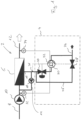
- the membrane filtration system comprises a standard membrane filtration system, for example a reverse osmosis filtration system provided with a concentrate draining device 4.
- the membrane filtration system comprises a membrane 6 with an inlet 8 on a first side of the membrane 6.
- a feed pump 10 On the second side of the membrane 6,there is a permeate outlet 12.
- This filtration system is provided with a recirculation channel 14 for circulating a concentrate or retentate, respectively, on the first or the entrance side of the membrane 6.
- This recirculation channel connects a concentrate outlet 16 and the inlet 8 behind the feed pump 10.
- a crossflow pump 18 for establishing and controlling the crossflow or circulating flow in the recirculation channel 14.
- the concentrate draining device 4 Connected to the concentrate outlet 16, there is the concentrate draining device 4 forming an active concentrate draining system. Downwards to the concentrate outlet, there is a pressure reduction valve 20 arranged in front of a pump in form of a at least one metering pump 2. In the first embodiment according to figure 1 , there is arranged a single metering pump, whereas in the second embodiment according to figure 2 , there are arranged two metering pumps 2 in parallel. These two metering pumps 2 may be operated simultaneously or in an alternating manner to, for example increase the output and/or to ensure a continuous operation, for example during maintenance.
- the metering 2 or metering pumps 2 may be reciprocating pumps, for example membrane pumps, which can be controlled in speed and/or stroke length to control and adjust a flow produced by the metering pump 2.
- the metering 2 or metering pumps 2 allow to precisely control the flow or amount of concentrate drained out of the recirculation channel 14. This allows to exactly set a recovery rate as explained below.
- the pressure reduction valve 20 in front of the one or two metering pumps 22 reduces the pressure in the concentrate outlet to an allowable maximum inlet pressure for the metering pump or pumps 22.
- the pressure reduction valve 20 may provide a constant inlet pressure for the metering pump or pumps 22 independent from the pressure present in the concentrate outlet 16.
- the pressure in the concentrate outlet 16 may change depending on the salinity or concentration of the concentrate.
- a flushing channel 26 In parallel to the pressure reduction valve 20 and the metering pump 22 or the metering pumps 22, there is arranged a flushing channel 26 with a flushing valve 28.
- the flushing channel 26 directly connects the concentrate outlet 16 and the brine outlet 24, thereby bypassing the metering pump 22 or metering pumps 22.
- the flushing valve 28 allows a higher flow compared to the metering pump or metering pumps 22.
- control device 30 which forms the entire control for the concentrate draining device.
- the control device 30 is integrated into the pump 22, preferably in form of an integrated controller controlling the pump 22 itself and the entire concentrate draining device.
- the controller for the concentrate draining device may also be realized as a separate control device.
- the flow sensor 32 is arranged the inlet 8, in this example behind the feed pump 10 and upwards from the connection of the crossflow channel.
- the second flow sensor 34 is arranged in the permeate outlet 12. Both flow sensors 32 and 34 are connected to the control device 30.
- a conductivity sensor 36 on the concentrate outlet 16 to detect the conductivity representing the salinity of the brine inside the concentrate outlet 16.
- the conductivity sensor 36 is connected to the control device 30.
- the control device 30 is connected to the flushing valve 28 for controlling the flushing valve 28.
- the pressure reduction valve 20 is controlled by the control device 30.
- the control device 30 is additionally connected to a second metering pump 22, which may be controlled as a slave pump, for example switched on and off by a command output from the control device 30.
- the control device 30 controls the recovery rate on basis of the flow signals received from the flow sensors 32, 34.
- the recovery rate represents the ratio of feed and produced liquid, i. e. permeate.
- the recovery rate is a ratio of the flow in the inlet 8 and the permeate flow in the permeate outlet 12.
- the recovery rate depends on the amount of concentrate drained from the concentrate outlet.
- This concentrate draining flow can be changed by changing the feed rate of the pump 22 or pumps 22, for example by changing the drive speed or the stroke length.
- the concentrate draining flow, produced by the pump or pumps 22 is controlled to keep the recovery rate in a predefined range, for example between a 50% and a 99,9%, i.e. near 100%.
- the concentration or salinity in the concentrate will increase. Therefore, from time-to-time flushing will become necessary.
- the flushing valve 28 is opened by the control device 30.
- the need for a flushing may be detected by a conductivity sensor 36, detecting the conductivity of the concentrate, which is representive for the salinity.
- a conductivity sensor may be arranged in the permeate outlet monitoring the concentration or salinity of the permeate. An increase of the concentration or salinity may indicate the need of a flushing.
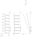
- FIG. 3 shows three diagrams showing the conductivity G, the permeate flow F and the cumulative concentrate volume V over time t.
- the solid lines represent the operation according to the invention, whereas the dashed lines represent the operation according to a prior art filtration system.
- the concentration in the feed or recirculation channel according to the invention is not constant, contrary to a prior art system.
- the flushing valve 28 is closed, and the concentrate is partly drained off by use of the pump 22.
- the salinity constantly increases until the point in time t 1 .
- the conductivity reaches a maximum G 2 , which is detected by the control device 30.
- the control device 30 opens the flushing valve 28, so that the concentrate on the entrance side of the membrane is flowing directly into the brine outlet 24.
- the flushing valve 28 is kept open until the water in the filtration system is exchanged with fresh feed water, which can be indicated by the conductivity reaching a minimum value or minimum threshold G 1 .
- this threshold G 1 is reached at the point t 2 .
- the control device 30 initiates a closing of the flushing valve 28. Then, during the further production, the conductivity increases again until the maximum value G 2 is reached at point in time t 3 .
- the conductivity G 1 represents a feed concentration.
- the conductivity G 1 represents a feed concentration.
- the permeate flow decreases during the flushing, i.e. between the points in time t 1 and t 2 or t 3 and t 4 .
- a cumulative concentrate volume V during the operation according to the invention increases stepwise during the flushing, contrary to the operation according to a prior art system showing a constantly increasing volume V (dashed line). Furthermore, it can be seen that the total cumulative concentrate volume is reduced by the operation according to the invention.
- the active draining by use of the concentrate draining device 4 allows a constant production of brine or concentrate and permeate. Both, the concentrate and the permeate are continuously produced and discharged. However, during flushing the output of the brine or concentrate increases as shown in figure 3 (lower diagram). Nevertheless, at the same time, the production of the permeate can be continued, but on a decreased level as shown in the diagram in the middle in figure 3 .
- the concentrate draining device 4 may be provided as an upgrade kit, which can be connected to a concentrate outlet 16 of an existing membrane filtration system 2.
- the control device 30 may have a sensor input allowing to connect existing flow sensors 32 and 34 in the conventional membrane filtration system and to receive sensor signals from the respective sensors.
- the sensors may be a part of the retrofit concentrate draining device and may be attached or inserted into the membrane filtration system 2 to be upgraded by the concentrate draining device.
- Such design allows to introduce a concentrate draining device 4 as described into an existing membrane filtration systems 2.
- Figure 4 shows an embodiment according to the invention not having the recirculation channel 14 as shown in the embodiments according to figures 1 and 2 .
- the concentrate draining device 14 is directly connected to the concentrate outlet 16 of the membrane unit.
- the several sensors are not shown in figure 4 , however, the arrangement of the sensors as discussed with reference to figures 1 and 2 may be the same.
- an arrangement of two or more metering pumps 22 in parallel as shown in figure 2 may be used in the embodiment as shown in figure 4 .
- Figure 5 shows a further alternative embodiment having a different position of the circulation pump 18.
- the recirculation pump 18 is arranged in the inlet or feed line 8 downstream the feed pump 10 with the recirculation channel 14 connected to the inlet or feed channel between the feed pump 10 and the recirculation pump 18.
- This arrangement of the recirculation pump 18 is beneficial, since the recirculation pump 18 can be flushed during the flushing when the flushing valve 18 is open.
- the sensors and the control device are not shown. The arrangement of the sensors and the control device may be the same as shown in figure 1 and 2 .
- two or more metering pumps 22 in parallel as shown in figure 2 may be used.
Landscapes
- Chemical & Material Sciences (AREA)
- Engineering & Computer Science (AREA)
- Water Supply & Treatment (AREA)
- Nanotechnology (AREA)
- Chemical Kinetics & Catalysis (AREA)
- Separation Using Semi-Permeable Membranes (AREA)
Priority Applications (4)
| Application Number | Priority Date | Filing Date | Title |
|---|---|---|---|
| EP21205628.7A EP4173695A1 (fr) | 2021-10-29 | 2021-10-29 | Système de filtration de membrane |
| CN202280069883.4A CN118103129A (zh) | 2021-10-29 | 2022-10-28 | 膜过滤系统 |
| EP22813147.0A EP4422784A1 (fr) | 2021-10-29 | 2022-10-28 | Système de filtration à membrane |
| PCT/EP2022/080196 WO2023073169A1 (fr) | 2021-10-29 | 2022-10-28 | Système de filtration à membrane |
Applications Claiming Priority (1)
| Application Number | Priority Date | Filing Date | Title |
|---|---|---|---|
| EP21205628.7A EP4173695A1 (fr) | 2021-10-29 | 2021-10-29 | Système de filtration de membrane |
Publications (1)
| Publication Number | Publication Date |
|---|---|
| EP4173695A1 true EP4173695A1 (fr) | 2023-05-03 |
Family
ID=78414546
Family Applications (2)
| Application Number | Title | Priority Date | Filing Date |
|---|---|---|---|
| EP21205628.7A Pending EP4173695A1 (fr) | 2021-10-29 | 2021-10-29 | Système de filtration de membrane |
| EP22813147.0A Pending EP4422784A1 (fr) | 2021-10-29 | 2022-10-28 | Système de filtration à membrane |
Family Applications After (1)
| Application Number | Title | Priority Date | Filing Date |
|---|---|---|---|
| EP22813147.0A Pending EP4422784A1 (fr) | 2021-10-29 | 2022-10-28 | Système de filtration à membrane |
Country Status (3)
| Country | Link |
|---|---|
| EP (2) | EP4173695A1 (fr) |
| CN (1) | CN118103129A (fr) |
| WO (1) | WO2023073169A1 (fr) |
Cited By (1)
| Publication number | Priority date | Publication date | Assignee | Title |
|---|---|---|---|---|
| WO2025068193A1 (fr) * | 2023-09-25 | 2025-04-03 | Inovaya | Unité de traitement d'eau et méthodes de nettoyage d'une telle unité |
Citations (10)
| Publication number | Priority date | Publication date | Assignee | Title |
|---|---|---|---|---|
| US20120103906A1 (en) * | 2009-07-05 | 2012-05-03 | Desalitech Ltd. | Closed Circuit Desalination Retrofit For Improved Performance Of Common Reverse Osmosis Systems |
| US20140311981A1 (en) * | 2013-04-19 | 2014-10-23 | Maple Expert Solutions, Inc. | Systems and Methods for Concentrating Sugar Content of Liquids |
| US20190209968A1 (en) * | 2016-09-07 | 2019-07-11 | Israel Aerospace Industries Ltd. | Method and system for liquid treatment |
| US20190224624A1 (en) * | 2017-02-15 | 2019-07-25 | Hitachi, Ltd. | Reverse osmosis treatment apparatus and reverse osmosis treatment method |
| US20200009506A1 (en) * | 2017-03-28 | 2020-01-09 | Bp Exploration Operating Company Limited | Process and System for Supplying a Low Salinity Injection Water |
| US10532938B2 (en) * | 2013-03-14 | 2020-01-14 | Bl Technologies, Inc. | Membrane filtration system with concentrate staging and concentrate recirculation, switchable stages, or both |
| US20200016538A1 (en) * | 2017-04-02 | 2020-01-16 | Desalitech Ltd. | Hydraulic-arm aided closed circuit batch-ro desalination apparatus of low energy and high recovery prospects |
| US20200023317A1 (en) * | 2017-04-01 | 2020-01-23 | Bl Technologies, Inc. | Method for reducing monovalent ions in concentrate of nanofiltration system and the nanofiltration system |
| US20200038808A1 (en) * | 2017-03-14 | 2020-02-06 | Desalstech Ltd | Integrated reverse osmosis and membrane cleaning systems for fouling prevention |
| US10960355B2 (en) * | 2017-09-25 | 2021-03-30 | Desalitech Ltd | Two-stage closed circuit desalination system of super RO characteristics |
Family Cites Families (2)
| Publication number | Priority date | Publication date | Assignee | Title |
|---|---|---|---|---|
| GB201319141D0 (en) * | 2013-10-30 | 2013-12-11 | Exmoor Pharma Concepts Ltd | Volume reduction devices and method |
| WO2018148542A1 (fr) * | 2017-02-09 | 2018-08-16 | Bergstrom Robert A | Système de dispersion de saumure |
-
2021
- 2021-10-29 EP EP21205628.7A patent/EP4173695A1/fr active Pending
-
2022
- 2022-10-28 WO PCT/EP2022/080196 patent/WO2023073169A1/fr not_active Ceased
- 2022-10-28 EP EP22813147.0A patent/EP4422784A1/fr active Pending
- 2022-10-28 CN CN202280069883.4A patent/CN118103129A/zh active Pending
Patent Citations (10)
| Publication number | Priority date | Publication date | Assignee | Title |
|---|---|---|---|---|
| US20120103906A1 (en) * | 2009-07-05 | 2012-05-03 | Desalitech Ltd. | Closed Circuit Desalination Retrofit For Improved Performance Of Common Reverse Osmosis Systems |
| US10532938B2 (en) * | 2013-03-14 | 2020-01-14 | Bl Technologies, Inc. | Membrane filtration system with concentrate staging and concentrate recirculation, switchable stages, or both |
| US20140311981A1 (en) * | 2013-04-19 | 2014-10-23 | Maple Expert Solutions, Inc. | Systems and Methods for Concentrating Sugar Content of Liquids |
| US20190209968A1 (en) * | 2016-09-07 | 2019-07-11 | Israel Aerospace Industries Ltd. | Method and system for liquid treatment |
| US20190224624A1 (en) * | 2017-02-15 | 2019-07-25 | Hitachi, Ltd. | Reverse osmosis treatment apparatus and reverse osmosis treatment method |
| US20200038808A1 (en) * | 2017-03-14 | 2020-02-06 | Desalstech Ltd | Integrated reverse osmosis and membrane cleaning systems for fouling prevention |
| US20200009506A1 (en) * | 2017-03-28 | 2020-01-09 | Bp Exploration Operating Company Limited | Process and System for Supplying a Low Salinity Injection Water |
| US20200023317A1 (en) * | 2017-04-01 | 2020-01-23 | Bl Technologies, Inc. | Method for reducing monovalent ions in concentrate of nanofiltration system and the nanofiltration system |
| US20200016538A1 (en) * | 2017-04-02 | 2020-01-16 | Desalitech Ltd. | Hydraulic-arm aided closed circuit batch-ro desalination apparatus of low energy and high recovery prospects |
| US10960355B2 (en) * | 2017-09-25 | 2021-03-30 | Desalitech Ltd | Two-stage closed circuit desalination system of super RO characteristics |
Cited By (1)
| Publication number | Priority date | Publication date | Assignee | Title |
|---|---|---|---|---|
| WO2025068193A1 (fr) * | 2023-09-25 | 2025-04-03 | Inovaya | Unité de traitement d'eau et méthodes de nettoyage d'une telle unité |
Also Published As
| Publication number | Publication date |
|---|---|
| WO2023073169A1 (fr) | 2023-05-04 |
| CN118103129A (zh) | 2024-05-28 |
| EP4422784A1 (fr) | 2024-09-04 |
Similar Documents
| Publication | Publication Date | Title |
|---|---|---|
| US12053742B2 (en) | Water conditioning systems having diversion devices | |
| KR102180787B1 (ko) | 역삼투 또는 나노여과에 의한 수처리 시스템 및 방법 | |
| US10821404B2 (en) | Control method for a filter system | |
| WO2017013027A1 (fr) | Procédés et systèmes de commande d'injection d'eau de mer | |
| CA3158644C (fr) | Procede et systeme pour effectuer un processus d'osmose inverse par lots a l'aide d'un reservoir avec une cloison mobile | |
| EP2745916B1 (fr) | Procédé de nettoyage d'un filtre de fluide liquide | |
| CN115364536B (zh) | 一种滤池反冲洗系统、滤池系统以及反冲洗方法 | |
| US10435306B2 (en) | Water treatment system and method | |
| EP4173695A1 (fr) | Système de filtration de membrane | |
| FI125583B (en) | A method for providing fluid circulation in membrane filtration and membrane filtration apparatus | |
| KR102572193B1 (ko) | 염분 농도 변화에 대응 가능한 고효율 가변형 고압 막여과 수처리 시스템 | |
| CN212680282U (zh) | 水肥一体化智能过滤反冲洗系统 | |
| JP7128887B2 (ja) | 多変量自動クロスフロー濾過制御 | |
| KR20190078762A (ko) | 정수기 | |
| CN215975082U (zh) | 净水机 | |
| US20210291118A1 (en) | Cleaning-in-place method and filter device | |
| CN212609697U (zh) | 净水水路及设备 | |
| EP2745917B1 (fr) | Ensemble filtre de fluide liquide | |
| US20130180908A1 (en) | Filter Backflush System for Entrained Filtration Elements | |
| CN210683297U (zh) | 一种净水控制装置及净水设备 | |
| EP4015068A1 (fr) | Procédé de commande pour un système de filtre à membrane et système de filtre à membrane | |
| EP2992946A1 (fr) | Appareil pour purifier un liquide et procédé de fonctionnement d'un tel appareil | |
| JP4853899B2 (ja) | 濁水処理用排水システム | |
| CN114074966A (zh) | 净水水路、方法及设备 | |
| CN121627134A (zh) | 一种基于反渗透膜的高效水处理系统及控制方法 |
Legal Events
| Date | Code | Title | Description |
|---|---|---|---|
| PUAI | Public reference made under article 153(3) epc to a published international application that has entered the european phase |
Free format text: ORIGINAL CODE: 0009012 |
|
| STAA | Information on the status of an ep patent application or granted ep patent |
Free format text: STATUS: THE APPLICATION HAS BEEN PUBLISHED |
|
| AK | Designated contracting states |
Kind code of ref document: A1 Designated state(s): AL AT BE BG CH CY CZ DE DK EE ES FI FR GB GR HR HU IE IS IT LI LT LU LV MC MK MT NL NO PL PT RO RS SE SI SK SM TR |