EP4173714A1 - Vorrichtung zur entnahme biologischer proben - Google Patents
Vorrichtung zur entnahme biologischer proben Download PDFInfo
- Publication number
- EP4173714A1 EP4173714A1 EP21306501.4A EP21306501A EP4173714A1 EP 4173714 A1 EP4173714 A1 EP 4173714A1 EP 21306501 A EP21306501 A EP 21306501A EP 4173714 A1 EP4173714 A1 EP 4173714A1
- Authority
- EP
- European Patent Office
- Prior art keywords
- reagent
- container
- liquid
- collector
- collector element
- Prior art date
- Legal status (The legal status is an assumption and is not a legal conclusion. Google has not performed a legal analysis and makes no representation as to the accuracy of the status listed.)
- Pending
Links
- 239000012472 biological sample Substances 0.000 title claims abstract description 68
- 239000003153 chemical reaction reagent Substances 0.000 claims abstract description 89
- 238000006243 chemical reaction Methods 0.000 claims description 89
- 239000007788 liquid Substances 0.000 claims description 87
- 238000012360 testing method Methods 0.000 claims description 15
- 230000000694 effects Effects 0.000 claims description 7
- 230000005484 gravity Effects 0.000 claims description 4
- 238000004458 analytical method Methods 0.000 claims description 2
- 239000000463 material Substances 0.000 description 15
- 238000000034 method Methods 0.000 description 14
- 230000000149 penetrating effect Effects 0.000 description 13
- 239000000523 sample Substances 0.000 description 12
- 239000012528 membrane Substances 0.000 description 11
- 239000000203 mixture Substances 0.000 description 11
- 102000004190 Enzymes Human genes 0.000 description 10
- 108090000790 Enzymes Proteins 0.000 description 10
- 230000003321 amplification Effects 0.000 description 10
- 238000003199 nucleic acid amplification method Methods 0.000 description 10
- 239000004698 Polyethylene Substances 0.000 description 8
- 239000004743 Polypropylene Substances 0.000 description 8
- 239000013543 active substance Substances 0.000 description 8
- 239000000872 buffer Substances 0.000 description 8
- 238000007834 ligase chain reaction Methods 0.000 description 8
- 239000000126 substance Substances 0.000 description 8
- 108020004707 nucleic acids Proteins 0.000 description 6
- 102000039446 nucleic acids Human genes 0.000 description 6
- 150000007523 nucleic acids Chemical class 0.000 description 6
- -1 polyethylene Polymers 0.000 description 6
- 239000000243 solution Substances 0.000 description 6
- 230000001419 dependent effect Effects 0.000 description 5
- DRBBFCLWYRJSJZ-UHFFFAOYSA-N N-phosphocreatine Chemical compound OC(=O)CN(C)C(=N)NP(O)(O)=O DRBBFCLWYRJSJZ-UHFFFAOYSA-N 0.000 description 4
- 241000700605 Viruses Species 0.000 description 4
- 229960000686 benzalkonium chloride Drugs 0.000 description 4
- CADWTSSKOVRVJC-UHFFFAOYSA-N benzyl(dimethyl)azanium;chloride Chemical compound [Cl-].C[NH+](C)CC1=CC=CC=C1 CADWTSSKOVRVJC-UHFFFAOYSA-N 0.000 description 4
- 239000007853 buffer solution Substances 0.000 description 4
- YMKDRGPMQRFJGP-UHFFFAOYSA-M cetylpyridinium chloride Chemical compound [Cl-].CCCCCCCCCCCCCCCC[N+]1=CC=CC=C1 YMKDRGPMQRFJGP-UHFFFAOYSA-M 0.000 description 4
- 229960001927 cetylpyridinium chloride Drugs 0.000 description 4
- 239000000835 fiber Substances 0.000 description 4
- 229920001223 polyethylene glycol Polymers 0.000 description 4
- 150000003856 quaternary ammonium compounds Chemical class 0.000 description 4
- 102000018120 Recombinases Human genes 0.000 description 3
- 108010091086 Recombinases Proteins 0.000 description 3
- CPKVUHPKYQGHMW-UHFFFAOYSA-N 1-ethenylpyrrolidin-2-one;molecular iodine Chemical compound II.C=CN1CCCC1=O CPKVUHPKYQGHMW-UHFFFAOYSA-N 0.000 description 2
- QKNYBSVHEMOAJP-UHFFFAOYSA-N 2-amino-2-(hydroxymethyl)propane-1,3-diol;hydron;chloride Chemical compound Cl.OCC(N)(CO)CO QKNYBSVHEMOAJP-UHFFFAOYSA-N 0.000 description 2
- 241000894006 Bacteria Species 0.000 description 2
- GHXZTYHSJHQHIJ-UHFFFAOYSA-N Chlorhexidine Chemical compound C=1C=C(Cl)C=CC=1NC(N)=NC(N)=NCCCCCCN=C(N)N=C(N)NC1=CC=C(Cl)C=C1 GHXZTYHSJHQHIJ-UHFFFAOYSA-N 0.000 description 2
- VEXZGXHMUGYJMC-UHFFFAOYSA-M Chloride anion Chemical compound [Cl-] VEXZGXHMUGYJMC-UHFFFAOYSA-M 0.000 description 2
- WTEVQBCEXWBHNA-UHFFFAOYSA-N Citral Natural products CC(C)=CCCC(C)=CC=O WTEVQBCEXWBHNA-UHFFFAOYSA-N 0.000 description 2
- 229920000742 Cotton Polymers 0.000 description 2
- 102000012410 DNA Ligases Human genes 0.000 description 2
- 108010061982 DNA Ligases Proteins 0.000 description 2
- 239000003298 DNA probe Substances 0.000 description 2
- 102100034343 Integrase Human genes 0.000 description 2
- 238000007397 LAMP assay Methods 0.000 description 2
- 102000003960 Ligases Human genes 0.000 description 2
- 108090000364 Ligases Proteins 0.000 description 2
- 239000012901 Milli-Q water Substances 0.000 description 2
- 108091034117 Oligonucleotide Proteins 0.000 description 2
- 239000002033 PVDF binder Substances 0.000 description 2
- 108091000080 Phosphotransferase Proteins 0.000 description 2
- 239000002202 Polyethylene glycol Substances 0.000 description 2
- 241000416918 Polyphylla Species 0.000 description 2
- 229920000153 Povidone-iodine Polymers 0.000 description 2
- 102000009609 Pyrophosphatases Human genes 0.000 description 2
- 108010009413 Pyrophosphatases Proteins 0.000 description 2
- 108010092799 RNA-directed DNA polymerase Proteins 0.000 description 2
- 239000007984 Tris EDTA buffer Substances 0.000 description 2
- JLCPHMBAVCMARE-UHFFFAOYSA-N [3-[[3-[[3-[[3-[[3-[[3-[[3-[[3-[[3-[[3-[[3-[[5-(2-amino-6-oxo-1H-purin-9-yl)-3-[[3-[[3-[[3-[[3-[[3-[[5-(2-amino-6-oxo-1H-purin-9-yl)-3-[[5-(2-amino-6-oxo-1H-purin-9-yl)-3-hydroxyoxolan-2-yl]methoxy-hydroxyphosphoryl]oxyoxolan-2-yl]methoxy-hydroxyphosphoryl]oxy-5-(5-methyl-2,4-dioxopyrimidin-1-yl)oxolan-2-yl]methoxy-hydroxyphosphoryl]oxy-5-(6-aminopurin-9-yl)oxolan-2-yl]methoxy-hydroxyphosphoryl]oxy-5-(6-aminopurin-9-yl)oxolan-2-yl]methoxy-hydroxyphosphoryl]oxy-5-(6-aminopurin-9-yl)oxolan-2-yl]methoxy-hydroxyphosphoryl]oxy-5-(6-aminopurin-9-yl)oxolan-2-yl]methoxy-hydroxyphosphoryl]oxyoxolan-2-yl]methoxy-hydroxyphosphoryl]oxy-5-(5-methyl-2,4-dioxopyrimidin-1-yl)oxolan-2-yl]methoxy-hydroxyphosphoryl]oxy-5-(4-amino-2-oxopyrimidin-1-yl)oxolan-2-yl]methoxy-hydroxyphosphoryl]oxy-5-(5-methyl-2,4-dioxopyrimidin-1-yl)oxolan-2-yl]methoxy-hydroxyphosphoryl]oxy-5-(5-methyl-2,4-dioxopyrimidin-1-yl)oxolan-2-yl]methoxy-hydroxyphosphoryl]oxy-5-(6-aminopurin-9-yl)oxolan-2-yl]methoxy-hydroxyphosphoryl]oxy-5-(6-aminopurin-9-yl)oxolan-2-yl]methoxy-hydroxyphosphoryl]oxy-5-(4-amino-2-oxopyrimidin-1-yl)oxolan-2-yl]methoxy-hydroxyphosphoryl]oxy-5-(4-amino-2-oxopyrimidin-1-yl)oxolan-2-yl]methoxy-hydroxyphosphoryl]oxy-5-(4-amino-2-oxopyrimidin-1-yl)oxolan-2-yl]methoxy-hydroxyphosphoryl]oxy-5-(6-aminopurin-9-yl)oxolan-2-yl]methoxy-hydroxyphosphoryl]oxy-5-(4-amino-2-oxopyrimidin-1-yl)oxolan-2-yl]methyl [5-(6-aminopurin-9-yl)-2-(hydroxymethyl)oxolan-3-yl] hydrogen phosphate Polymers Cc1cn(C2CC(OP(O)(=O)OCC3OC(CC3OP(O)(=O)OCC3OC(CC3O)n3cnc4c3nc(N)[nH]c4=O)n3cnc4c3nc(N)[nH]c4=O)C(COP(O)(=O)OC3CC(OC3COP(O)(=O)OC3CC(OC3COP(O)(=O)OC3CC(OC3COP(O)(=O)OC3CC(OC3COP(O)(=O)OC3CC(OC3COP(O)(=O)OC3CC(OC3COP(O)(=O)OC3CC(OC3COP(O)(=O)OC3CC(OC3COP(O)(=O)OC3CC(OC3COP(O)(=O)OC3CC(OC3COP(O)(=O)OC3CC(OC3COP(O)(=O)OC3CC(OC3COP(O)(=O)OC3CC(OC3COP(O)(=O)OC3CC(OC3COP(O)(=O)OC3CC(OC3COP(O)(=O)OC3CC(OC3COP(O)(=O)OC3CC(OC3CO)n3cnc4c(N)ncnc34)n3ccc(N)nc3=O)n3cnc4c(N)ncnc34)n3ccc(N)nc3=O)n3ccc(N)nc3=O)n3ccc(N)nc3=O)n3cnc4c(N)ncnc34)n3cnc4c(N)ncnc34)n3cc(C)c(=O)[nH]c3=O)n3cc(C)c(=O)[nH]c3=O)n3ccc(N)nc3=O)n3cc(C)c(=O)[nH]c3=O)n3cnc4c3nc(N)[nH]c4=O)n3cnc4c(N)ncnc34)n3cnc4c(N)ncnc34)n3cnc4c(N)ncnc34)n3cnc4c(N)ncnc34)O2)c(=O)[nH]c1=O JLCPHMBAVCMARE-UHFFFAOYSA-N 0.000 description 2
- 238000010521 absorption reaction Methods 0.000 description 2
- 229940027983 antiseptic and disinfectant quaternary ammonium compound Drugs 0.000 description 2
- 239000003139 biocide Substances 0.000 description 2
- 239000003795 chemical substances by application Substances 0.000 description 2
- 229960003260 chlorhexidine Drugs 0.000 description 2
- 229940043350 citral Drugs 0.000 description 2
- 239000011248 coating agent Substances 0.000 description 2
- 238000000576 coating method Methods 0.000 description 2
- 239000003599 detergent Substances 0.000 description 2
- 229940044949 eucalyptus oil Drugs 0.000 description 2
- 239000010642 eucalyptus oil Substances 0.000 description 2
- WTEVQBCEXWBHNA-JXMROGBWSA-N geranial Chemical compound CC(C)=CCC\C(C)=C\C=O WTEVQBCEXWBHNA-JXMROGBWSA-N 0.000 description 2
- 230000036571 hydration Effects 0.000 description 2
- 238000006703 hydration reaction Methods 0.000 description 2
- 150000002500 ions Chemical class 0.000 description 2
- 230000002934 lysing effect Effects 0.000 description 2
- 239000011159 matrix material Substances 0.000 description 2
- 239000002773 nucleotide Substances 0.000 description 2
- 125000003729 nucleotide group Chemical group 0.000 description 2
- IUCHKMAZAWJNBJ-RCYXVVTDSA-N oleanolic acid 3-O-beta-D-glucosiduronic acid Chemical compound O([C@H]1CC[C@]2(C)[C@H]3CC=C4[C@@]([C@@]3(CC[C@H]2C1(C)C)C)(C)CC[C@]1(CCC(C[C@H]14)(C)C)C(O)=O)[C@@H]1O[C@H](C(O)=O)[C@@H](O)[C@H](O)[C@H]1O IUCHKMAZAWJNBJ-RCYXVVTDSA-N 0.000 description 2
- 229950007002 phosphocreatine Drugs 0.000 description 2
- 102000020233 phosphotransferase Human genes 0.000 description 2
- 239000004033 plastic Substances 0.000 description 2
- 229920003023 plastic Polymers 0.000 description 2
- 229920000573 polyethylene Polymers 0.000 description 2
- 238000003752 polymerase chain reaction Methods 0.000 description 2
- 229920001155 polypropylene Polymers 0.000 description 2
- 229960001621 povidone-iodine Drugs 0.000 description 2
- 102000004169 proteins and genes Human genes 0.000 description 2
- 108090000623 proteins and genes Proteins 0.000 description 2
- 239000008213 purified water Substances 0.000 description 2
- 239000011535 reaction buffer Substances 0.000 description 2
- 230000008929 regeneration Effects 0.000 description 2
- 238000011069 regeneration method Methods 0.000 description 2
- 238000001179 sorption measurement Methods 0.000 description 2
- 229940111630 tea tree oil Drugs 0.000 description 2
- 239000010677 tea tree oil Substances 0.000 description 2
- 239000012780 transparent material Substances 0.000 description 2
- 150000008130 triterpenoid saponins Chemical class 0.000 description 2
- XLYOFNOQVPJJNP-UHFFFAOYSA-N water Chemical compound O XLYOFNOQVPJJNP-UHFFFAOYSA-N 0.000 description 2
- 238000001514 detection method Methods 0.000 description 1
- 238000002405 diagnostic procedure Methods 0.000 description 1
- 201000010099 disease Diseases 0.000 description 1
- 208000037265 diseases, disorders, signs and symptoms Diseases 0.000 description 1
- 230000005284 excitation Effects 0.000 description 1
- 238000011901 isothermal amplification Methods 0.000 description 1
- 244000052769 pathogen Species 0.000 description 1
- 210000003296 saliva Anatomy 0.000 description 1
Images

Classifications
-
- B—PERFORMING OPERATIONS; TRANSPORTING
- B01—PHYSICAL OR CHEMICAL PROCESSES OR APPARATUS IN GENERAL
- B01L—CHEMICAL OR PHYSICAL LABORATORY APPARATUS FOR GENERAL USE
- B01L3/00—Containers or dishes for laboratory use, e.g. laboratory glassware; Droppers
- B01L3/50—Containers for the purpose of retaining a material to be analysed, e.g. test tubes
- B01L3/502—Containers for the purpose of retaining a material to be analysed, e.g. test tubes with fluid transport, e.g. in multi-compartment structures
- B01L3/5029—Containers for the purpose of retaining a material to be analysed, e.g. test tubes with fluid transport, e.g. in multi-compartment structures using swabs
-
- B—PERFORMING OPERATIONS; TRANSPORTING
- B01—PHYSICAL OR CHEMICAL PROCESSES OR APPARATUS IN GENERAL
- B01L—CHEMICAL OR PHYSICAL LABORATORY APPARATUS FOR GENERAL USE
- B01L3/00—Containers or dishes for laboratory use, e.g. laboratory glassware; Droppers
- B01L3/52—Containers specially adapted for storing or dispensing a reagent
- B01L3/527—Containers specially adapted for storing or dispensing a reagent for a plurality of reagents
-
- A—HUMAN NECESSITIES
- A61—MEDICAL OR VETERINARY SCIENCE; HYGIENE
- A61B—DIAGNOSIS; SURGERY; IDENTIFICATION
- A61B10/00—Instruments for taking body samples for diagnostic purposes; Other methods or instruments for diagnosis, e.g. for vaccination diagnosis, sex determination or ovulation-period determination; Throat striking implements
- A61B10/0045—Devices for taking samples of body liquids
-
- A—HUMAN NECESSITIES
- A61—MEDICAL OR VETERINARY SCIENCE; HYGIENE
- A61B—DIAGNOSIS; SURGERY; IDENTIFICATION
- A61B10/00—Instruments for taking body samples for diagnostic purposes; Other methods or instruments for diagnosis, e.g. for vaccination diagnosis, sex determination or ovulation-period determination; Throat striking implements
- A61B10/0096—Casings for storing test samples
-
- B—PERFORMING OPERATIONS; TRANSPORTING
- B01—PHYSICAL OR CHEMICAL PROCESSES OR APPARATUS IN GENERAL
- B01L—CHEMICAL OR PHYSICAL LABORATORY APPARATUS FOR GENERAL USE
- B01L2200/00—Solutions for specific problems relating to chemical or physical laboratory apparatus
- B01L2200/02—Adapting objects or devices to another
- B01L2200/025—Align devices or objects to ensure defined positions relative to each other
-
- B—PERFORMING OPERATIONS; TRANSPORTING
- B01—PHYSICAL OR CHEMICAL PROCESSES OR APPARATUS IN GENERAL
- B01L—CHEMICAL OR PHYSICAL LABORATORY APPARATUS FOR GENERAL USE
- B01L2200/00—Solutions for specific problems relating to chemical or physical laboratory apparatus
- B01L2200/16—Reagents, handling or storing thereof
-
- B—PERFORMING OPERATIONS; TRANSPORTING
- B01—PHYSICAL OR CHEMICAL PROCESSES OR APPARATUS IN GENERAL
- B01L—CHEMICAL OR PHYSICAL LABORATORY APPARATUS FOR GENERAL USE
- B01L2300/00—Additional constructional details
- B01L2300/04—Closures and closing means
- B01L2300/041—Connecting closures to device or container
- B01L2300/042—Caps; Plugs
-
- B—PERFORMING OPERATIONS; TRANSPORTING
- B01—PHYSICAL OR CHEMICAL PROCESSES OR APPARATUS IN GENERAL
- B01L—CHEMICAL OR PHYSICAL LABORATORY APPARATUS FOR GENERAL USE
- B01L2300/00—Additional constructional details
- B01L2300/04—Closures and closing means
- B01L2300/041—Connecting closures to device or container
- B01L2300/045—Connecting closures to device or container whereby the whole cover is slidable
-
- B—PERFORMING OPERATIONS; TRANSPORTING
- B01—PHYSICAL OR CHEMICAL PROCESSES OR APPARATUS IN GENERAL
- B01L—CHEMICAL OR PHYSICAL LABORATORY APPARATUS FOR GENERAL USE
- B01L2300/00—Additional constructional details
- B01L2300/04—Closures and closing means
- B01L2300/046—Function or devices integrated in the closure
-
- B—PERFORMING OPERATIONS; TRANSPORTING
- B01—PHYSICAL OR CHEMICAL PROCESSES OR APPARATUS IN GENERAL
- B01L—CHEMICAL OR PHYSICAL LABORATORY APPARATUS FOR GENERAL USE
- B01L2300/00—Additional constructional details
- B01L2300/04—Closures and closing means
- B01L2300/046—Function or devices integrated in the closure
- B01L2300/047—Additional chamber, reservoir
-
- B—PERFORMING OPERATIONS; TRANSPORTING
- B01—PHYSICAL OR CHEMICAL PROCESSES OR APPARATUS IN GENERAL
- B01L—CHEMICAL OR PHYSICAL LABORATORY APPARATUS FOR GENERAL USE
- B01L2300/00—Additional constructional details
- B01L2300/06—Auxiliary integrated devices, integrated components
- B01L2300/0609—Holders integrated in container to position an object
-
- B—PERFORMING OPERATIONS; TRANSPORTING
- B01—PHYSICAL OR CHEMICAL PROCESSES OR APPARATUS IN GENERAL
- B01L—CHEMICAL OR PHYSICAL LABORATORY APPARATUS FOR GENERAL USE
- B01L2300/00—Additional constructional details
- B01L2300/06—Auxiliary integrated devices, integrated components
- B01L2300/0672—Integrated piercing tool
-
- B—PERFORMING OPERATIONS; TRANSPORTING
- B01—PHYSICAL OR CHEMICAL PROCESSES OR APPARATUS IN GENERAL
- B01L—CHEMICAL OR PHYSICAL LABORATORY APPARATUS FOR GENERAL USE
- B01L2300/00—Additional constructional details
- B01L2300/06—Auxiliary integrated devices, integrated components
- B01L2300/069—Absorbents; Gels to retain a fluid
-
- B—PERFORMING OPERATIONS; TRANSPORTING
- B01—PHYSICAL OR CHEMICAL PROCESSES OR APPARATUS IN GENERAL
- B01L—CHEMICAL OR PHYSICAL LABORATORY APPARATUS FOR GENERAL USE
- B01L2300/00—Additional constructional details
- B01L2300/08—Geometry, shape and general structure
- B01L2300/0832—Geometry, shape and general structure cylindrical, tube shaped
-
- B—PERFORMING OPERATIONS; TRANSPORTING
- B01—PHYSICAL OR CHEMICAL PROCESSES OR APPARATUS IN GENERAL
- B01L—CHEMICAL OR PHYSICAL LABORATORY APPARATUS FOR GENERAL USE
- B01L2300/00—Additional constructional details
- B01L2300/08—Geometry, shape and general structure
- B01L2300/0861—Configuration of multiple channels and/or chambers in a single devices
- B01L2300/0867—Multiple inlets and one sample wells, e.g. mixing, dilution
-
- B—PERFORMING OPERATIONS; TRANSPORTING
- B01—PHYSICAL OR CHEMICAL PROCESSES OR APPARATUS IN GENERAL
- B01L—CHEMICAL OR PHYSICAL LABORATORY APPARATUS FOR GENERAL USE
- B01L2400/00—Moving or stopping fluids
- B01L2400/06—Valves, specific forms thereof
- B01L2400/0677—Valves, specific forms thereof phase change valves; Meltable, freezing, dissolvable plugs; Destructible barriers
- B01L2400/0683—Valves, specific forms thereof phase change valves; Meltable, freezing, dissolvable plugs; Destructible barriers mechanically breaking a wall or membrane within a channel or chamber
Definitions
- the present disclosure relates to device for collecting one or more biological samples, which may be subsequently used for molecular biology processing techniques such as nucleic acid amplification and/or detection.
- PCR Polymerase Chain Reaction
- RPA Recombinase Polymerase Amplification
- LAMP Loop-Mediated Isothermal Amplification
- Devices for collecting one or more biological samples - in particular for collecting saliva from the mouth of the consumer - are known from WO 2020/191232 A1 , WO 2020/106345 A1 , WO 2020/238035 A1 and EP 3 028 030 A1 .
- Those devices comprise a wick as collector element.
- the wick is very soft and is difficult to maintain and fasten into the housing of the device.
- the object of the present disclosure is to provide a device for collecting one or more biological samples, wherein the one or more biological samples can be tested and/or analyzed more easily.
- the present disclosure is directed to a device for collecting one or more biological samples as defined in independent claim 1.
- the dependent claims depict embodiments of the present disclosure.
- a device for collecting one or more biological samples comprising a housing and a collector element, wherein the collector element is designed to collect one or more biological samples.
- the device comprises a cap element which can be mounted on the housing, wherein the cap element comprises a reagent or an element comprising a reagent.
- the device may comprise a container for storing liquid.
- the collector element may be designed to allow the passage of the liquid so that at least part of the liquid can pass through a channel and through the collector element to wash out the one or more biological samples out of the collector element at least partially for testing/analyzing purposes.
- the reagent or the element comprising a reagent may be contained in the cap which can be mounted on the housing for covering the collector element.
- the reagent is released to the mixture for testing/analyzing the one or more samples on site.
- the housing may consist of several separate housing parts.
- the collector element may generally have an elongated shape extending from the first end to the second end of the collector element.
- the cross-sectional shape of the collector element (in a plane which is perpendicular to the axis of the collector element) may at least partially be circular, oval or rectangular (in examples with rounded corners).
- the section of the collector element at its first end may have a conical section. In addition or alternatively, the first end of the collector element may be pointed.
- the purpose of the collector element is to collect and/or absorb one or more biological samples.
- the biological samples may stick on the outer surface of the first end of the collector element.
- the biological samples may be absorbed within the collector element. Therefore, the collector element should allow the passage of liquid at least partially in order to take up absorb a greater amount of the biological sample(s).
- Suitable materials for the collector element include cotton-based materials, or a plastic based matrix such as PE (polyethylene), PP (polypropylene) or PVDF (polyvinylidene fluoride) or a combination thereof, which can be manufactured in a range of densities to retain biological samples of different viscosities.
- the collector element may be made of a combination of PE and PP, wherein the PP may be the core portion and the PE may be the outer coating, due to its particular properties on absorption of liquid via its capillary structure, and adsorption which is minimal with regards to nucleic acids.
- the collector element may comprise fibers (in examples, pressed fibers) made of one or more of these materials.
- the material of the collector element may be porous or may have an internal channel structure, and may have hydrophilic properties in order to absorb a large amount of liquid biological samples more quickly.
- the porosity may be at least 50%, more specifically at least 70%, most specifically at least 80%.
- the collector element may extend between a first end and a second end, the first end of the collector element protruding out of the housing for collecting the one or more biological samples, the second end of the collector element being arranged within the housing.
- the collector element may allow the passage of the liquid from the container, in particular a buffer solution and/or a reagent solution, through the collector element in order to drain the biological sample(s) out of the collector element.
- the collector element may allow the passage of liquid from its second end which is arranged in the housing, to its first end which protrudes out of the housing, or from the outer surface near the second end to the first end.
- An element for indicating and/or measuring a reaction between the reagent and the at least one biological sample may be arranged within or on the cap element, in particular an element for indicating the pH value.
- the liquid from the container drains the biological sample(s) into the cap element, and the reagent is then released to the liquid containing the biological sample(s).
- This may cause a reaction which may result in a certain pH value which can be indicated by the element for indicating the pH value, in particular a pH strip indicating a certain color dependent on the specific pH value.
- the reaction may cause a fluorescence effect so that a certain reaction is indicated by the emitted fluorescence light.
- a window may be provided in the cap element so that the user can see the effect of the reaction (e.g. a certain color of the pH strip or the emitted fluorescence light).
- the cap element may be made of or comprise a transparent material.
- the cap element may comprise a reaction chamber, and wherein the reagent or the element comprising a reagent and/or the element for indicating and/or measuring a reaction is arranged within the reaction chamber.
- a holder may be arranged within the reaction chamber. The holder may be designed to premount the reagent or the element comprising a reagent and/or the element for indicating and/or measuring a reaction on or within the holder, before the holder is mounted within the reaction chamber. This ensures that one or both elements are securely positioned within the reaction chamber to ensure a proper test result.
- the holder may hold the reagent or the element comprising a reagent and/or the element for indicating and/or measuring a reaction by shape-fit, snap-fit and/or press-fit features.
- the holder itself may also be held within the reaction chamber by shape-fit, snap-fit and/or press-fit features.
- the cap element may have an opening so that liquid from the container which has passed through the collector element can reach the reaction chamber within the cap. This opening may at least partially comprise a converging shape for funneling the liquid into the reaction chamber.
- the holder may have an end portion facing the collector element which at least partially comprises a converging shape for funneling a liquid into the reaction chamber.
- the cap element may be held on the housing by shape-fit, snap-fit and/or press-fit features to securely hold the cap element in position during use, in particular when the liquid drains the sample(s) into the reaction chamber.
- the cap element may comprise ribs and/or protrusions for engaging at least part of the front portion of the housing for holding the cap element in a predefined position.
- the predefined position may be in an axially aligned position with respect to the longitudinal axis of the housing.
- the device may comprise a container for storing liquid and a channel for guiding the liquid to the collector element.
- the container may initially be in a closed state for storing the liquid and may further comprise a release mechanism for opening the container or a passage from the container to the channel so that liquid stored in the container can enter the channel from the container and reach the collector element.
- the container may have an opening which is closed by a membrane, wherein the release mechanism comprises a cutting or penetrating member for opening the container by a cutting or penetrating actuation. This can - for example - be achieved by moving the container from a first position into (or further into) the housing to a second position, wherein the cutting/penetrating member may be fixedly arranged within the housing.
- the membrane is closed in the first position of the container, and wherein the membrane is cut open or penetrated by the cutting or penetrating member in the second position of the container.
- the liquid can thus be released when needed, i.e. after the one or more samples have been collected, and when a user wants to analyze/test the sample(s).
- liquid stored in the container can reach the collector element through the channel when the release mechanism is open, wherein at least part of the liquid can pass through the collector element and into the reaction chamber, for example by gravity acting on the liquid when the container is in a position vertically above the collector element.
- the container may be compressible to force the liquid through the collector element.
- the housing and the container may also have a mechanism to retain the container in its first position such that the initial actuation force required to move the container into the housing is higher than the subsequent actuation force needed to cut open or penetrate the membrane.
- the retaining mechanism may comprise at least two internal protrusions on the inner side of the housing forming a circumferential groove between the protrusions, and a circumferential protrusion on the outer side of the container, wherein the circumferential protrusion is held within the circumferential groove of the housing.
- the housing may comprise a locking mechanism for maintaining the container in its first position, and which can be unlocked so that the container can be moved into its second position.
- This locking mechanism requires an unlocking actuation by a user which is different compared to a pushing or moving actuation on the container itself.
- the locking mechanism may comprise at least one lever which can be operated by a user to disengage a protrusion on the container (which protrusion may be identical to the previously mentioned protrusion on the container).
- the locking mechanism may comprise a bayonet connection such that the container must be rotated first to unlock the axial position of the container so that the container can subsequently be moved in axial direction into the housing.
- the device of the present disclosure may be in a state in which the container does not yet contain the liquid.
- the container may already comprise a liquid, in particular a buffer solution and/or a reagent solution, i.e. the device may be in prefilled state.
- amplification methods may be used (i.e. the device of the present disclosure may be designed for carrying out one of these methods), for example a recombinase polymerase amplification (RPA) which is a low temperature DNA and/or RNA amplification technique, or a ligase chain reaction (LCR).
- RPA recombinase polymerase amplification
- LCR ligase chain reaction
- the liquid stored in the container may be a buffer liquid and may contain purified water, milli-q water and buffer (e.g. TRIS-Cl / TE buffer), for example a Tris-HCl buffer.
- buffer e.g. TRIS-Cl / TE buffer
- the buffer liquid also contains PEG as crowding agent.
- the reagents located in the cap may include a group of materials, such as primers, probes additionally to the enzymes (ligase or polymerase) and nucleotides. Generally, the reagents located in the cap are dependent on the used amplification method.
- a suitable reagent composition for RPA may contain enzymes (in particular enzymes for polymerase and/or enzymes for reverse transcriptase), proteins, primers, probes, oligonucleotides and reaction components necessary for the RPA reaction including reaction buffer, polyethylene glycol, pyrophosphatase, a regeneration system such as kinase/phosphocreatine system, or a mixture thereof.
- a suitable reagent composition for LCR may contain enzymes for DNA ligase and/or DNA probes.
- the collector element may additionally be treated.
- reagents or active agents may be covalently bound to the collector element by chemical linkages through functionalisation (e.g. -OH groups), or they may be dried into the material of the collector element and become active on hydration with the sample.
- the collector element may be treated to provide means of lysing virus, in particular a treatment to form a negatively charged surface (so as to retain the positively charged ions of the sample) or a treatment with anionic detergent.
- Possible active agents that render the collector element functionalized may lyse bacteria or viruses. These active agents may be quaternary ammonium compounds (QAC) and/or biocidal agents.
- QAC quaternary ammonium compounds
- Examples of these active agents are: Citral, Eucalyptus oil, Tea tree oil, Chlorhexidine, triterpenoid saponin, Polyphylla saponin I, Povidone-iodine, Cetyl pyridinium chloride (CPC), Benzalkonium chloride (BAC), Dequoalinium chloride.
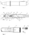
- Figures 1 shows a device for collecting one or more biological samples according to an embodiment of the present disclosure.
- Figure 2 shows a cross-section through a device for collecting one or more biological samples according to another embodiment of the present disclosure which is a variation of the embodiment of Figure 1 .
- the device of the present disclosure comprises a housing 1 and a collector element 2, wherein the collector element is designed to collect one or more biological samples.
- the device further comprises a cap element 5 (not shown in Figure 1 ) which can be mounted on the housing, wherein the cap element 5 comprises a reagent 6 or an element comprising a reagent. With that, it is possible to test/analyze the one or more biological samples on site, if desired.
- the device may comprise a container 3 for storing liquid 7.
- the collector element 2 may be designed to allow the passage of the liquid 7 so that at least part of the liquid can pass through a channel 4 and through the collector element 2 to wash out the one or more biological samples out of the collector element at least partially for testing/analyzing purposes.
- the reagent 6 or the element comprising a reagent is contained a reaction chamber 8 within the cap element 5.
- the reagent is released to the mixture for testing/analyzing the one or more samples on site.
- the purpose of the collector element 2 is to collect and/or absorb one or more biological samples.
- the biological samples may stick on the outer surface of the first end 2a of the collector element.
- the biological samples may be absorbed within the collector element. Therefore, the collector element should allow the passage of liquid at least partially in order to take up absorb a greater amount of the biological sample(s).
- the material of the collector element may be porous or may have an internal channel structure, and may have hydrophilic properties in order to absorb a large amount of liquid biological samples more quickly.
- Suitable materials for the collector element 2 include cotton-based materials, or a plastic based matrix such as PE (polyethylene), PP (polypropylene) or PVDF (polyvinylidene fluoride) or a combination thereof, which can be manufactured in a range of densities to retain biological samples of different viscosities.
- the collector element is made of a combination of PE and PP, wherein the PP is the core portion and the PE is the outer coating, due to its particular properties on absorption of liquid via its capillary structure, and adsorption which is minimal with regards to nucleic acids.
- the collector element may comprise fibers (in examples, pressed fibers) made of one or more of these materials.
- the material of the collector element may be porous or may have an internal channel structure, and may have hydrophilic properties in order to absorb a large amount of liquid biological samples more quickly.
- the porosity may be at least 50%, more specifically at least 70%, most specifically at least 80%.
- the density of the collector element may range from 0.1 to 0.25 g/cm 3 .
- the collector element 2 may have two ends, the first end 2a of the collector element protruding out of the housing for collecting the one or more biological samples, the second end 2a of the collector element being arranged within the housing.
- the collector element may allow the passage of the liquid from the container 3, in particular a buffer solution and/or a reagent solution, through the collector element in order to drain the biological sample(s) out of the collector element and into the reaction chamber 8.
- the collector element may allow the passage of liquid from its second end which is arranged in the housing, to its first end which protrudes out of the housing, or from the outer surface near the second end to the first end.
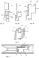
- Figure 3 shows a cap element according to an embodiment the present disclosure including the parts which may be arranged within the cap element in a disassembled state, in particular the reagent 6 (or the element comprising a reagent).
- the reagent 6 (or the element comprising a reagent) may have any shape; in the shown embodiment, it has the shape of a sphere.
- an element 14 for indicating and/or measuring a reaction between the reagent and the at least one biological sample is also arranged within or on the cap element, in particular an element 14 or a strip for indicating the pH value.
- the liquid 7 from the container 3 drains the biological sample(s) into the cap element 5, and the reagent 6 is then released to the liquid containing the biological sample(s). This may cause a reaction which may result in a certain pH value which can be indicated by the element 14 for indicating the pH value, in particular a pH strip indicating a certain color dependent on the specific pH value.
- the cap element 5 may comprise a reaction chamber 8, wherein the reagent 6 (or the element comprising a reagent) and/or the element 14 for indicating and/or measuring a reaction are arranged within the reaction chamber 8.
- a holder 16 as shown in Figures 3 to 5 may be arranged within the reaction chamber (see also Figure 6 ).
- the holder 16 may be designed to premount the reagent 6 (or the element comprising a reagent) and/or the element 14 for indicating and/or measuring a reaction on or within the holder 6, before the holder is mounted within the reaction chamber.
- Figures 4a to 4c show how the element 14 (for example a pH strip or an element comprising a reagent for causing a fluorescence effect when coming into contact with the biological sample or the mixture of the reagent and the biological sample) is mounted on the holder 16.
- Figure 5 shows the premounted state in which both, the element 14 and the reagent 6 are mounted on the holder 16.
- the holder 16 ensures that the element 14 and the reagent 6 are securely positioned within the reaction chamber 8 to ensure a proper test result.
- the holder 16 may hold the reagent 6 (or the element comprising a reagent) and/or the element for indicating and/or measuring a reaction by shape-fit, snap-fit and/or press-fit features.
- the reagent 6 is held by four posts 6a to 6d which hold the reagent 6 (or the element comprising a reagent) by a press-fit, i.e. the inner free diameter of the posts 6a to 6d is slightly smaller than the diameter the spherical shape of the reagent 6.
- the posts 6a to 6d may also have recesses (in particular concave recesses) for achieving a shape-fit for holding the reagent 6.
- the element 14 is also held by a post 6e by press-fit, i.e. the distance of the gap formed between the posts 6a/6b and the post 6e is slightly smaller than the width of the pH strip.
- the holder itself may also be held within the reaction chamber by shape-fit, snap-fit and/or press-fit features.
- the cap element 5 may have one or more internal protrusions 12 which can be slightly deformed when the holder 16 is inserted into the reaction chamber 8, and which serve to correctly position the holder 16 within the reaction chamber 8 (as shown in Figures 6 , 7a and 7b ).
- the cap element 5 may have an opening 13 (see Figures 2 , 7a and 7b ) so that liquid from the container 3 which has passed through the collector element 2 can reach the reaction chamber 8 within the cap element 5.
- This opening may at least partially comprise a converging shape 15 for funneling the liquid into the reaction chamber (see Figures 2 and 7a ).
- the holder 16 may have an end portion 16a facing the collector element which at least partially comprises a converging shape for funneling the liquid into the reaction chamber 8.
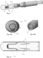
- Figures 8a to 8c shows a cap element 5 and a holder 16 according to another embodiment of the present disclosure together with an element 14 for indicating a reaction and a reagent 6 (or an element containing a reagent).
- a reagent 6 or an element containing a reagent
- FIG. 8c shows a cap element 5 and a holder 16 according to another embodiment of the present disclosure together with an element 14 for indicating a reaction and a reagent 6 (or an element containing a reagent).
- the element 14 for indicating and/or measuring a reaction is premounted on the holder 16 by two posts 17a, 17b which have two internal grooves extending in longitudinal direction for inserting the element 14.
- the reagent 6 (or an element containing the reagent) is held within the reaction chamber 8 by the distal end 16b of the holder 16. Therefore, the reagent 6 is placed into the reaction chamber 8 first.
- the holder 16 (together with the premounted element 14) is inserted into the reaction chamber 8 for holding the reagent 6 in place.
- the holder 16 may be mounted within the cap element 5 by shape-fit, snap-fit and/or press-fit features.
- one or more protrusions 12 are provided on the inner side of the cap element for providing a snap-fit of the holder 16 within the reaction chamber 8.
- the cap element has an opening 13 which has at least partially comprise a converging shape 15 for funneling the liquid into the reaction chamber.
- the holder 16 has an end portion 16a facing the collector element 2 which at least partially comprises a converging shape for funneling the liquid into the reaction chamber 8.
- Figure 11 shows a cap element according to another embodiment of the present disclosure together with a substance 30 which may comprise a reagent and/or a substance for indicating a reaction.
- a substance 30 which may comprise a reagent and/or a substance for indicating a reaction.
- This embodiment does not require a holder as discussed above, whereas it should be understood that a holder may be used.
- the substance 30 is directly held at the bottom or on an internal surface of the reaction chamber 8.
- the substance 30 may be applied in a dissolved state to the reaction chamber 8, and then dried so that the substance 30 adheres to the bottom or on an internal surface of the reaction chamber 8.
- the biological sample may react with the reagent and/or the substance for indicating a reaction.
- the reaction may cause a fluorescence effect (either auto-fluorescence or fluorescence caused by applying an excitation light) so that the user can directly see the result of the reaction via the fluorescence effect.
- a window may be provided in the cap element, or the cap element may comprise or be made of a transparent material.
- the cap element may be held on the housing by shape-fit, snap-fit and/or press-fit features to securely hold the cap element in position during use, in particular when the liquid drains the sample(s) into the reaction chamber.
- Figure 8c shows protrusions 17 on the inner side of the cap element 5 which are designed to engage a circumferential groove on the housing.
- the cap element 5 may be fitted on the housing by a shape-fit as shown in Figure 2 , for example by providing a circumferential protrusion 18 on the housing which abuts the proximal end 19 of the cap element 5.
- the cap element may comprise ribs 20 and/or protrusions for engaging at least part of the front portion of the housing for holding the cap element in a predefined position, which may be in an axially aligned position with respect to the longitudinal axis of the housing.
- the device may comprise a container for storing liquid and a channel for guiding the liquid to the collector element.
- the container may initially be in a closed state for storing the liquid and may further comprise a release mechanism for opening the container or a passage from the container to the channel so that liquid stored in the container can enter the channel from the container and reach the collector element.
- the container may have an opening which is closed by a membrane 31, wherein the release mechanism comprises a cutting or penetrating member 32 for opening the container by a cutting or penetrating actuation (see Fig. 2 ).
- the membrane is closed in the first position of the container, and wherein the membrane is cut open or penetrated by the cutting or penetrating member in the second position of the container.
- the liquid can thus be released when needed, i.e. after the one or more samples have been collected, and when a user wants to analyze/test the sample(s).
- liquid stored in the container can reach the collector element through the channel when the release mechanism is open, wherein at least part of the liquid can pass through the collector element and into the reaction chamber, for example by gravity acting on the liquid when the container is in a position vertically above the collector element.
- the container may be compressible to force the liquid through the collector element.
- the housing and the container may also have a mechanism to retain the container in its first position such that the initial actuation force required to move the container into the housing is higher than the subsequent actuation force needed to cut open or penetrate the membrane. This feature ensures that the first position is maintained as a preset position.
- the retaining mechanism may comprise two internal protrusions on the inner side of the housing forming a circumferential groove between the protrusions, and a circumferential protrusion on the outer side of the container, wherein the circumferential protrusion is held within the circumferential groove of the housing.
- the housing may comprise a locking mechanism for maintaining the container in its first position, and which can be unlocked so that the container can be moved into its second position.
- This locking mechanism requires an unlocking actuation by a user which is different compared to a pushing or moving actuation on the container itself.
- the locking mechanism may comprise at least one lever which can be operated by a user to disengage a protrusion on the container (which protrusion may be identical to the previously mentioned protrusion on the container).
- the locking mechanism may comprise a bayonet connection such that the container must be rotated first to unlock the axial position of the container so that the container can subsequently be moved in axial direction into the housing.
- the device of the present disclosure may be in a state in which the container does not yet contain the liquid.
- the container may already comprise a liquid, in particular a buffer solution and/or a reagent solution, i.e. the device may be in prefilled state.
- amplification methods may be used (i.e. the device of the present disclosure may be designed for carrying out one of these methods), for example a recombinase polymerase amplification (RPA) which is a low temperature DNA and/or RNA amplification technique, or a ligase chain reaction (LCR).
- RPA recombinase polymerase amplification
- LCR ligase chain reaction
- the liquid stored in the container may be a buffer liquid and may contain purified water, milli-q water and buffer (e.g. TRIS-Cl / TE buffer), for example a Tris-HCl buffer.
- buffer e.g. TRIS-Cl / TE buffer
- the buffer liquid also contains PEG as crowding agent.
- the reagents located in the cap may include a group of materials, such as primers, probes additionally to the enzymes (ligase or polymerase) and nucleotides. Generally, the reagents located in the cap are dependent on the used amplification method.
- a suitable reagent composition for RPA may contain enzymes (in particular enzymes for polymerase and/or enzymes for reverse transcriptase), proteins, primers, probes, oligonucleotides and reaction components necessary for the RPA reaction including reaction buffer, polyethylene glycol, pyrophosphatase, a regeneration system such as kinase/phosphocreatine system, or a mixture thereof.
- a suitable reagent composition for LCR may contain enzymes for DNA ligase and/or DNA probes.
- the collector element may additionally be treated.
- reagents or active agents may be covalently bound to the collector element by chemical linkages through functionalisation (e.g. -OH groups), or they may be dried into the material of the collector element and become active on hydration with the sample.
- the collector element may be treated to provide means of lysing virus, in particular a treatment to form a negatively charged surface (so as to retain the positively charged ions of the sample) or a treatment with anionic detergent.
- Possible active agents that render the collector element functionalized may lyse bacteria or viruses. These active agents may be quaternary ammonium compounds (QAC) and/or biocidal agents.
- QAC quaternary ammonium compounds
- Examples of these active agents are: Citral, Eucalyptus oil, Tea tree oil, Chlorhexidine, triterpenoid saponin, Polyphylla saponin I, Povidone-iodine, Cetyl pyridinium chloride (CPC), Benzalkonium chloride (BAC), Dequoalinium chloride.
Landscapes
- Health & Medical Sciences (AREA)
- Chemical & Material Sciences (AREA)
- Clinical Laboratory Science (AREA)
- Chemical Kinetics & Catalysis (AREA)
- Analytical Chemistry (AREA)
- General Health & Medical Sciences (AREA)
- Hematology (AREA)
- Medicinal Chemistry (AREA)
- Investigating Or Analysing Biological Materials (AREA)
Priority Applications (3)
| Application Number | Priority Date | Filing Date | Title |
|---|---|---|---|
| EP21306501.4A EP4173714A1 (de) | 2021-10-27 | 2021-10-27 | Vorrichtung zur entnahme biologischer proben |
| PCT/EP2022/079950 WO2023073032A1 (en) | 2021-10-27 | 2022-10-26 | Device for collecting biological samples |
| US18/705,301 US20250222448A1 (en) | 2021-10-27 | 2022-10-26 | Device for collecting biological samples |
Applications Claiming Priority (1)
| Application Number | Priority Date | Filing Date | Title |
|---|---|---|---|
| EP21306501.4A EP4173714A1 (de) | 2021-10-27 | 2021-10-27 | Vorrichtung zur entnahme biologischer proben |
Publications (1)
| Publication Number | Publication Date |
|---|---|
| EP4173714A1 true EP4173714A1 (de) | 2023-05-03 |
Family
ID=78592789
Family Applications (1)
| Application Number | Title | Priority Date | Filing Date |
|---|---|---|---|
| EP21306501.4A Pending EP4173714A1 (de) | 2021-10-27 | 2021-10-27 | Vorrichtung zur entnahme biologischer proben |
Country Status (1)
| Country | Link |
|---|---|
| EP (1) | EP4173714A1 (de) |
Citations (8)
| Publication number | Priority date | Publication date | Assignee | Title |
|---|---|---|---|---|
| US20090155124A1 (en) * | 2007-12-13 | 2009-06-18 | John Wan | Collection and assay device for biological fluid |
| EP3028030A1 (de) | 2013-08-01 | 2016-06-08 | Ancestry.com DNA, LLC | Probenentnahmevorrichtung |
| US20180153522A1 (en) * | 2014-06-10 | 2018-06-07 | Dxterity Diagnostics Incorporation | Devices and methods for collecting and stabilizing biological samples |
| WO2020106345A1 (en) | 2018-11-21 | 2020-05-28 | Sri International | Sample collection and dispensing device |
| WO2020191232A1 (en) | 2019-03-19 | 2020-09-24 | Ancestry.Com Dna, Llc | Sample collection kit including cap having selectively movable sleeve |
| DE102019204633A1 (de) * | 2019-04-02 | 2020-10-08 | Anvajo GmbH | Vorrichtung und Verfahren zum Aufnehmen und Handhaben einer flüssigen Probe und einer Substanz |
| WO2020238035A1 (zh) | 2019-05-31 | 2020-12-03 | 万华普曼生物工程有限公司 | 唾液采检装置 |
| WO2021209228A1 (en) * | 2020-04-16 | 2021-10-21 | Readygo Diagnostics Limited | Sampling device |
-
2021
- 2021-10-27 EP EP21306501.4A patent/EP4173714A1/de active Pending
Patent Citations (8)
| Publication number | Priority date | Publication date | Assignee | Title |
|---|---|---|---|---|
| US20090155124A1 (en) * | 2007-12-13 | 2009-06-18 | John Wan | Collection and assay device for biological fluid |
| EP3028030A1 (de) | 2013-08-01 | 2016-06-08 | Ancestry.com DNA, LLC | Probenentnahmevorrichtung |
| US20180153522A1 (en) * | 2014-06-10 | 2018-06-07 | Dxterity Diagnostics Incorporation | Devices and methods for collecting and stabilizing biological samples |
| WO2020106345A1 (en) | 2018-11-21 | 2020-05-28 | Sri International | Sample collection and dispensing device |
| WO2020191232A1 (en) | 2019-03-19 | 2020-09-24 | Ancestry.Com Dna, Llc | Sample collection kit including cap having selectively movable sleeve |
| DE102019204633A1 (de) * | 2019-04-02 | 2020-10-08 | Anvajo GmbH | Vorrichtung und Verfahren zum Aufnehmen und Handhaben einer flüssigen Probe und einer Substanz |
| WO2020238035A1 (zh) | 2019-05-31 | 2020-12-03 | 万华普曼生物工程有限公司 | 唾液采检装置 |
| WO2021209228A1 (en) * | 2020-04-16 | 2021-10-21 | Readygo Diagnostics Limited | Sampling device |
Similar Documents
| Publication | Publication Date | Title |
|---|---|---|
| DK3112473T3 (en) | DOWNSTREAM PREPARATION OF AN ALKALIC PHOSPHATASE | |
| JP7145998B2 (ja) | 試料調製装置 | |
| US6150178A (en) | Diagnostic testing device | |
| US20230225715A1 (en) | Sampling device | |
| WO2012027048A2 (en) | Biological fluid sampling and storage apparatus for remote use | |
| KR20020043551A (ko) | 시료 방출구를 갖춘 일회용 시험약병 | |
| EP1861019A1 (de) | Vorrichtung zur entnahme einer oralen flüssigkeit | |
| US20240041439A1 (en) | Systems and methods for preservation of a cervicovaginal fluid sample | |
| US20090081772A1 (en) | Method and device for collecting cellular material from cells isolated on a filter | |
| US20250012677A1 (en) | Device for collecting biological samples | |
| EP4338838A1 (de) | Vorrichtung zur entnahme biologischer proben | |
| EP4173714A1 (de) | Vorrichtung zur entnahme biologischer proben | |
| US20250222448A1 (en) | Device for collecting biological samples | |
| CN219044930U (zh) | 核酸提取装置 | |
| EP4340738B1 (de) | Probenahmevorrichtung | |
| EP4173707A1 (de) | Vorrichtung zur entnahme biologischer proben | |
| US20250033034A1 (en) | Device for collecting biological samples | |
| US20260124619A1 (en) | Device for collecting biological samples | |
| US20250255586A1 (en) | Device for collecting biological samples | |
| EP4173711A1 (de) | Vorrichtung zum sammeln von biologischen proben | |
| CN117769463A (zh) | 样品制备 | |
| EP4359128A2 (de) | Probenvorbereitung | |
| JP2016524132A (ja) | 固体生体試料の分析用試料ホルダ | |
| HK1197434B (en) | Method and apparatus for acquiring blood for testing |
Legal Events
| Date | Code | Title | Description |
|---|---|---|---|
| PUAI | Public reference made under article 153(3) epc to a published international application that has entered the european phase |
Free format text: ORIGINAL CODE: 0009012 |
|
| STAA | Information on the status of an ep patent application or granted ep patent |
Free format text: STATUS: THE APPLICATION HAS BEEN PUBLISHED |
|
| AK | Designated contracting states |
Kind code of ref document: A1 Designated state(s): AL AT BE BG CH CY CZ DE DK EE ES FI FR GB GR HR HU IE IS IT LI LT LU LV MC MK MT NL NO PL PT RO RS SE SI SK SM TR |
|
| STAA | Information on the status of an ep patent application or granted ep patent |
Free format text: STATUS: REQUEST FOR EXAMINATION WAS MADE |
|
| 17P | Request for examination filed |
Effective date: 20231018 |
|
| RBV | Designated contracting states (corrected) |
Designated state(s): AL AT BE BG CH CY CZ DE DK EE ES FI FR GB GR HR HU IE IS IT LI LT LU LV MC MK MT NL NO PL PT RO RS SE SI SK SM TR |