EP4173797A1 - Dispositif et procédé de formage d'ébauches en plastique en récipients en plastique dotés d'un étranglement réglable - Google Patents
Dispositif et procédé de formage d'ébauches en plastique en récipients en plastique dotés d'un étranglement réglable Download PDFInfo
- Publication number
- EP4173797A1 EP4173797A1 EP22204151.9A EP22204151A EP4173797A1 EP 4173797 A1 EP4173797 A1 EP 4173797A1 EP 22204151 A EP22204151 A EP 22204151A EP 4173797 A1 EP4173797 A1 EP 4173797A1
- Authority
- EP
- European Patent Office
- Prior art keywords
- pressure
- plastic
- valve
- bar
- preferably greater
- Prior art date
- Legal status (The legal status is an assumption and is not a legal conclusion. Google has not performed a legal analysis and makes no representation as to the accuracy of the status listed.)
- Granted
Links
Images



Classifications
-
- B—PERFORMING OPERATIONS; TRANSPORTING
- B29—WORKING OF PLASTICS; WORKING OF SUBSTANCES IN A PLASTIC STATE IN GENERAL
- B29C—SHAPING OR JOINING OF PLASTICS; SHAPING OF MATERIAL IN A PLASTIC STATE, NOT OTHERWISE PROVIDED FOR; AFTER-TREATMENT OF THE SHAPED PRODUCTS, e.g. REPAIRING
- B29C49/00—Blow-moulding, i.e. blowing a preform or parison to a desired shape within a mould; Apparatus therefor
- B29C49/42—Component parts, details or accessories; Auxiliary operations
- B29C49/4284—Means for recycling or reusing auxiliaries or materials, e.g. blowing fluids or energy
-
- B—PERFORMING OPERATIONS; TRANSPORTING
- B29—WORKING OF PLASTICS; WORKING OF SUBSTANCES IN A PLASTIC STATE IN GENERAL
- B29C—SHAPING OR JOINING OF PLASTICS; SHAPING OF MATERIAL IN A PLASTIC STATE, NOT OTHERWISE PROVIDED FOR; AFTER-TREATMENT OF THE SHAPED PRODUCTS, e.g. REPAIRING
- B29C49/00—Blow-moulding, i.e. blowing a preform or parison to a desired shape within a mould; Apparatus therefor
- B29C49/42—Component parts, details or accessories; Auxiliary operations
- B29C49/78—Measuring, controlling or regulating
- B29C49/783—Measuring, controlling or regulating blowing pressure
-
- B—PERFORMING OPERATIONS; TRANSPORTING
- B29—WORKING OF PLASTICS; WORKING OF SUBSTANCES IN A PLASTIC STATE IN GENERAL
- B29C—SHAPING OR JOINING OF PLASTICS; SHAPING OF MATERIAL IN A PLASTIC STATE, NOT OTHERWISE PROVIDED FOR; AFTER-TREATMENT OF THE SHAPED PRODUCTS, e.g. REPAIRING
- B29C49/00—Blow-moulding, i.e. blowing a preform or parison to a desired shape within a mould; Apparatus therefor
- B29C49/42—Component parts, details or accessories; Auxiliary operations
- B29C49/4284—Means for recycling or reusing auxiliaries or materials, e.g. blowing fluids or energy
- B29C49/42845—Recycling or reusing of fluid, e.g. pressure
- B29C49/42855—Blowing fluids, e.g. reducing fluid consumption
-
- B—PERFORMING OPERATIONS; TRANSPORTING
- B29—WORKING OF PLASTICS; WORKING OF SUBSTANCES IN A PLASTIC STATE IN GENERAL
- B29C—SHAPING OR JOINING OF PLASTICS; SHAPING OF MATERIAL IN A PLASTIC STATE, NOT OTHERWISE PROVIDED FOR; AFTER-TREATMENT OF THE SHAPED PRODUCTS, e.g. REPAIRING
- B29C49/00—Blow-moulding, i.e. blowing a preform or parison to a desired shape within a mould; Apparatus therefor
- B29C49/42—Component parts, details or accessories; Auxiliary operations
- B29C49/4289—Valve constructions or configurations, e.g. arranged to reduce blowing fluid consumption
-
- B—PERFORMING OPERATIONS; TRANSPORTING
- B29—WORKING OF PLASTICS; WORKING OF SUBSTANCES IN A PLASTIC STATE IN GENERAL
- B29C—SHAPING OR JOINING OF PLASTICS; SHAPING OF MATERIAL IN A PLASTIC STATE, NOT OTHERWISE PROVIDED FOR; AFTER-TREATMENT OF THE SHAPED PRODUCTS, e.g. REPAIRING
- B29C49/00—Blow-moulding, i.e. blowing a preform or parison to a desired shape within a mould; Apparatus therefor
- B29C49/42—Component parts, details or accessories; Auxiliary operations
- B29C49/78—Measuring, controlling or regulating
- B29C49/783—Measuring, controlling or regulating blowing pressure
- B29C2049/7831—Measuring, controlling or regulating blowing pressure characterised by pressure values or ranges
-
- B—PERFORMING OPERATIONS; TRANSPORTING
- B29—WORKING OF PLASTICS; WORKING OF SUBSTANCES IN A PLASTIC STATE IN GENERAL
- B29C—SHAPING OR JOINING OF PLASTICS; SHAPING OF MATERIAL IN A PLASTIC STATE, NOT OTHERWISE PROVIDED FOR; AFTER-TREATMENT OF THE SHAPED PRODUCTS, e.g. REPAIRING
- B29C49/00—Blow-moulding, i.e. blowing a preform or parison to a desired shape within a mould; Apparatus therefor
- B29C49/42—Component parts, details or accessories; Auxiliary operations
- B29C49/78—Measuring, controlling or regulating
- B29C49/783—Measuring, controlling or regulating blowing pressure
- B29C2049/7832—Blowing with two or more pressure levels
- B29C2049/7833—Blowing with three or more pressure levels
-
- B—PERFORMING OPERATIONS; TRANSPORTING
- B29—WORKING OF PLASTICS; WORKING OF SUBSTANCES IN A PLASTIC STATE IN GENERAL
- B29C—SHAPING OR JOINING OF PLASTICS; SHAPING OF MATERIAL IN A PLASTIC STATE, NOT OTHERWISE PROVIDED FOR; AFTER-TREATMENT OF THE SHAPED PRODUCTS, e.g. REPAIRING
- B29C49/00—Blow-moulding, i.e. blowing a preform or parison to a desired shape within a mould; Apparatus therefor
- B29C49/02—Combined blow-moulding and manufacture of the preform or the parison
- B29C49/06—Injection blow-moulding
-
- B—PERFORMING OPERATIONS; TRANSPORTING
- B29—WORKING OF PLASTICS; WORKING OF SUBSTANCES IN A PLASTIC STATE IN GENERAL
- B29C—SHAPING OR JOINING OF PLASTICS; SHAPING OF MATERIAL IN A PLASTIC STATE, NOT OTHERWISE PROVIDED FOR; AFTER-TREATMENT OF THE SHAPED PRODUCTS, e.g. REPAIRING
- B29C49/00—Blow-moulding, i.e. blowing a preform or parison to a desired shape within a mould; Apparatus therefor
- B29C49/08—Biaxial stretching during blow-moulding
- B29C49/10—Biaxial stretching during blow-moulding using mechanical means for prestretching
- B29C49/12—Stretching rods
-
- B—PERFORMING OPERATIONS; TRANSPORTING
- B29—WORKING OF PLASTICS; WORKING OF SUBSTANCES IN A PLASTIC STATE IN GENERAL
- B29K—INDEXING SCHEME ASSOCIATED WITH SUBCLASSES B29B, B29C OR B29D, RELATING TO MOULDING MATERIALS OR TO MATERIALS FOR MOULDS, REINFORCEMENTS, FILLERS OR PREFORMED PARTS, e.g. INSERTS
- B29K2067/00—Use of polyesters or derivatives thereof, as moulding material
- B29K2067/003—PET, i.e. poylethylene terephthalate
-
- B—PERFORMING OPERATIONS; TRANSPORTING
- B29—WORKING OF PLASTICS; WORKING OF SUBSTANCES IN A PLASTIC STATE IN GENERAL
- B29L—INDEXING SCHEME ASSOCIATED WITH SUBCLASS B29C, RELATING TO PARTICULAR ARTICLES
- B29L2031/00—Other particular articles
- B29L2031/712—Containers; Packaging elements or accessories, Packages
- B29L2031/7158—Bottles
-
- Y—GENERAL TAGGING OF NEW TECHNOLOGICAL DEVELOPMENTS; GENERAL TAGGING OF CROSS-SECTIONAL TECHNOLOGIES SPANNING OVER SEVERAL SECTIONS OF THE IPC; TECHNICAL SUBJECTS COVERED BY FORMER USPC CROSS-REFERENCE ART COLLECTIONS [XRACs] AND DIGESTS
- Y02—TECHNOLOGIES OR APPLICATIONS FOR MITIGATION OR ADAPTATION AGAINST CLIMATE CHANGE
- Y02P—CLIMATE CHANGE MITIGATION TECHNOLOGIES IN THE PRODUCTION OR PROCESSING OF GOODS
- Y02P70/00—Climate change mitigation technologies in the production process for final industrial or consumer products
- Y02P70/10—Greenhouse gas [GHG] capture, material saving, heat recovery or other energy efficient measures, e.g. motor control, characterised by manufacturing processes, e.g. for rolling metal or metal working
Definitions
- the present invention relates to a device and a method for forming plastic preforms into plastic containers.
- the forming device and in particular the blow molding machine or stretch blow molding machine has a number of blow molding stations with blow molds which form a cavity which corresponds to the negative shape of the plastic container to be produced.
- the plastic preforms are usually stretched in the longitudinal direction within the blow molds with a stretching rod and then formed into the plastic containers by being subjected to a flowable medium.
- the flowable medium is applied in several different pressure stages with different pressure levels.
- the high-pressure air requirement per container thus results from the relief quantity in the case of well-adjusted recycling.
- This results from the container volume, the dead space volume of the valve block and the relief pressure.
- the container volume is given and cannot be changed, so that the dead space volume and the relief pressure can be reduced must be made.
- the dead space volume can be reduced, for example, by a suitable arrangement of the valves and small flow channels, and the relief pressure by appropriate process settings.
- the relief pressure must be higher than the first pressure P1, since otherwise the air cannot be recycled without an additional compression unit.
- the required pressure P1 also depends on the geometries and flow rates of the valve block and cannot be easily reduced. Typical known pressures P1 are between 6.5 and 11.5 bar, so the relief pressures are between 7 and 12 bar.
- the shaping device or the valve block also includes an adjustable pre-blow (throttle), the volume flow being adjusted by varying the pre-blow pressure.
- throttle an adjustable pre-blow
- the throttle is currently a 4-stage, adjustable pre-blowing throttle, which is adjusted manually. Between the throttle and the valve there is an unthrottled volume of air which pre-fills the dead space.
- the present invention is therefore based on the object of providing a device and a method which enable faster blow molding with lower energy and, in particular, air consumption.
- a minimum compressed air requirement should be achieved across different container sizes without making compromises in the bottle quality or quality of expression. According to the invention, this object is achieved by the subject matter of the independent claims.
- Advantageous embodiments and developments are the subject of the dependent claims.
- the invention is therefore directed towards a device for forming plastic preforms into plastic containers, with a forming device which has a large number of forming stations, each of which has a blow mold, within which the plastic preforms can be formed into the plastic containers, the forming stations each having a stretch rod for stretching of the plastic preform in its longitudinal direction and an application device for applying a flowable medium and in particular compressed air to the plastic container.
- the application device preferably comprises a blast piston and a blast nozzle.
- the conversion device has at least four pressure reservoirs for the flowable medium, which each have predetermined pressures P1, Pi, P+, P2, with a pressure Pi being lower than a pressure P+ and the pressure P+ being lower than a pressure P2, and a valve block with at least five process valves V1, Vi, V+, V2, V Ex , the application device being suitable and intended for establishing a fluid connection between the valve block and a mouth area of the plastic preform in order to apply the pressurized flowable medium to the plastic preforms.
- the Process valves are suitable and intended for subjecting the plastic preform to different pressures, with at least one process valve being suitable and intended for establishing a connection between the plastic container and an environment.
- the process valves preferably apply the flowable medium to the plastic preforms independently of one another, with the valves particularly preferably being arranged parallel to one another.
- Establishing the connection between the plastic container and the environment by means of a process valve and in particular the process valve V Ex preferably corresponds to the relief of the plastic container, preferably in the last recycling stage. If the plastic preforms are subjected to four pressures, for example, four recycling or relief stages preferably also follow, with the relieved or recycled compressed air from a recycling stage being used to pressurize the subsequent plastic preform in the next lower pressure stage. The compressed air that remains after the last recycling stage or is not used for the blow molding process of a subsequent container is released to the environment. It is therefore preferred if this amount of compressed air is as small as possible.
- the shaping device is preferably a blow molding machine and particularly preferably a stretch blow molding machine.
- the forming station is preferably a blow molding station and particularly preferably a stretch blow molding station.
- the stretching rod of the shaping device is preferably an electric stretching rod or stretching unit.
- a maximum stretching speed of the electrical stretching unit is greater than 1.4 m/s, preferably greater than 1.8 m/s, particularly preferably greater than 2.2 m/s.
- the electric stretching unit is preferably a linear motor and particularly preferably an electromagnetic direct drive in a preferably tubular form. It would also be conceivable for the stretching rod to be guided via preferably guide curves or a pneumatically driven stretching rod, or a combination of pneumatic and electric drives.
- a connecting space is preferably provided downstream or after the process valves.
- the connection space is understood to mean an area or space between the valve block and the plastic container to be formed, or an area downstream or after the valve, between the valve and the plastic container. It says preferred each process valve is connected to or connected to the connecting space.
- the pressure P1 is preferably a pre-blowing pressure
- the pressures Pi and P+ are intermediate blowing pressures
- the pressure P2 is a final blowing pressure.
- the pressure P1 can be greater, less than or equal to the pressure Pi and/or P+.
- At least one adjustable throttle is arranged between the pressure reservoir P1 and the process valve V1 52mm 2 is.
- the cross-sectional adjustment of the throttle is preferably reproducible.
- a volume between the throttle or the pressure reservoir and the valve is particularly preferably varied or changed.
- the flow rate of the at least one throttle is preferably determined by an adjustable throttle cross section, the throttle cross section being adjustable such that it is no smaller than 19.7 mm 2 , preferably no smaller than 12.6 mm 2 and particularly preferably no smaller than 7.1 mm is 2 .
- the throttle cross-section is particularly preferably adjustable up to a maximum of 29 mm 2 , preferably up to a maximum of 38 mm 2 and particularly preferably up to a maximum of 52 mm 2 .
- An adjustment range for the throttle cross section is therefore preferably 19.7 mm 2 to 52 mm 2 , preferably 12.6 mm 2 to 38 mm 2 and particularly preferably 7.1 mm 2 to 29 mm 2 .
- An adjustment range for the throttle cross section is particularly preferably 7.1 mm 2 to 52 mm 2 , preferably in any range within this range.
- this also enables better reproducibility of the container quality and the switching time of the process valve V1 and thus a higher rotational speed of the blow wheel.
- mapping the process air is through the inventive device achieves a steeper rise and fall in the pressure curve, resulting in higher station performance.
- the combination of the adjustable throttle and the additional intermediate pressure stage enables a smaller dead space, lower control air pressure/volume, which leads to lower energy consumption.
- a modular valve block with an inexpensive basic design can also be provided.
- the compressed air consumption is preferably reduced in particular by the additional intermediate stage P+, as is explained in more detail in particular in the figures. Due to these optimized pressure flows, fast pressure rise times are possible and thus fast station performance, so that the blowing time is reduced and the container is blown faster.
- the blowing nozzle is preferably lifted off the mouth of the container or removed from the container when there is still pressure in the container. Previously, as is known from the applicant's internal prior art, this was only withdrawn when there was no longer any pressure in the container.
- the holding time when the maximum pressure P2 is applied is particularly preferably increased. This leads in particular to improved container quality.
- the process valves are advantageously arranged in such a way that a minimal dead space is formed within the valve block.
- the at least four valves are preferably arranged in more than two levels, so that the dead space volume is less than 150 ml, preferably less than 100 ml and particularly preferably less than 80 ml.
- the air consumption can be further reduced by a small dead space.
- the dead space of the valve block is preferably understood to mean the entire space between the mouthpiece of the container and the valve seats and pressure sensor, which space can be filled with air.
- the process valve, which connects the connection space to an environment is preferably an independent process valve.
- the reshaping device preferably has a pressure pad, the connections and/or lines and/or the dead volume to the pressure pad being in total preferably less than 120 ml, preferably less than 80 ml and particularly preferably less than 60 ml. to further reduce compressed air consumption. If the design of the forming device or the blow mold allows it, ie if it has a suitable mold carrier construction, the pressure pad can preferably also be omitted. A shaping device without a pressure pad is therefore also preferred, which also reduces the consumption of compressed air.
- a dead space in the BKIR (bottom cooling in series) stretching rod and the associated valve is also preferred to be less than 50 ml, preferably less than 30 ml and particularly preferably less than 15 ml. Bottom cooling in series can preferably also be omitted.
- the relief pressures are preferably less than 8 bar, preferably less than 7 bar and particularly preferably less than 6 bar. If the plastic preform and/or the plastic container is subjected to four pressures or pressure levels, there are preferably also four recycling stages, as already mentioned above.
- the process valves VEx and V2 preferably have small switching volumes and are each switched only once during the forming of the plastic container.
- the process valves P1, Pi and P+ are preferably switched twice, once when the plastic container is subjected to the corresponding pressure level and once during the associated recycling stage. It is therefore advantageous to design the process valves P1, Pi and P+ in such a way that they require little control air volume and little control air pressure.
- the control volume for an entire process sequence of a plastic container to be produced is preferably less than 60 ml, preferably less than 45 ml and particularly preferably less than 30 ml.
- the air consumption is accordingly preferably less than 0.6 g, preferably less than 0.45 g and particularly preferably less than 0. 3g This can preferably be achieved by pressure-compensated valves.
- the pressure P1 can be set variably and is preferably less than 8 bar and more preferably less than 6 bar and preferably more than 3 bar and more preferably more than 4 bar and/or the pressure P2 can be set variably and preferably more than 16 bar, preferably greater than 18 bar and particularly preferably greater than 22 bar.
- the pressure level of these pressure stages can therefore easily be adapted to the current requirements, such as different container sizes.
- the pressures for P1 and P2 are conflicting requirements, since a small P1 pressure reduces air consumption, but a large P2 pressure can achieve good container quality.
- the pressure reservoirs and the valve block are connected via lines and in particular compressed air lines whose smallest cross sections are greater than or equal to 110 mm 2 , preferably greater than or equal to 140 mm 2 and particularly preferably greater than or equal to 155 mm 2 .
- This is preferably a connection between the application device and the pressure reservoirs for the pressures Pi and/or P+ and/or P2.
- the application device is movably mounted in the valve block.
- the application device and in particular the blast piston and/or the blast nozzle can be moved in a longitudinal direction of the plastic container and/or towards the plastic container.
- a forming station particularly preferably each forming station, has at least one sensor for determining a pressure, this being a pressure in particular between a process valve and the plastic preform. It is thus possible to determine and/or monitor the pressure level and thus also indirectly the air consumption. For example, an error message can preferably also be output in a suitable or known manner if the pressure is too high and/or too low.
- the device has exactly five process valves (V1, Vi, V+, V2, VEx ), ie five valves are arranged within the valve block and/or on the valve block.
- V1, Vi, V+, V2, VEx process valves
- VEx additional (intermediate) pressure stage
- five process valves and an adjustable throttle is therefore preferably proposed in order to achieve the smallest possible dead space and save energy.
- this combination enables low compressed air consumption with high container quality.
- a flow cross section of the process valves Vi and V+ and/or V2 and/or V Ex between the respective process valve and the application device is greater than or equal to 150 mm 2 and preferably greater than or equal to 200 mm 2 .
- a flow cross-section of an annular gap between the inner wall of the mouth area of the plastic preform and the stretch rod is narrowed by less than 50% for mouth areas with an inner diameter of less than 22 mm, preferably by optimized inner geometries of the blowing nozzles.
- a stroke movement or an amplitude of the stroke movement of the blast piston is greater than 15 mm, preferably greater than 12 mm and preferably greater than 10 mm and less than 60 mm, preferably less than 45 mm and preferably less than 30 mm.
- the process valves Vi and/or V+ and/or V2 and/or V Ex are preferably pneumatically pilot-controlled seat valves, the seat of which has a cross-sectional area greater than 150 mm 2 and preferably greater than 200 mm 2 .
- the process valves Vi and/or V+ and/or V2 and/or V Ex are preferably pneumatically pilot-controlled seat valves whose working stroke is less than 6 mm. The stroke is decisive for the service life and the control air consumption of the valve. A small stroke correspondingly leads to a longer service life and lower air consumption.
- the process valves Vi and/or V+ and/or V2 and/or V Ex are pneumatically pilot-controlled at least partially compensated seat valves.
- the process valves Vi and/or V+ and/or V2 and/or V Ex are preferably pneumatically pre-controlled seat valves, which are controlled by control devices, such as preferably electric pilots, which switch under program control.
- connection space mentioned and in particular of a connection space outer wall is a circle larger than 40 mm and smaller than 80 mm.
- Connection bores of valves preferably penetrate the basic shape of the outer wall of the connection space at almost the same height.
- the at least one throttle can be adjusted between at least two, preferably at least four and particularly preferably at least five fixed positions, with the adjustment preferably being able to be produced by a rotatable cylinder with different passage bores.
- the at least one throttle can be variably adjusted by changing the distance between two screen parts, which are moved towards one another by moving, or by exchanging insert parts.
- the at least one throttle can be adjusted manually, by motor or without tools.
- a volume between the throttle or the pressure reservoir and the process valve can particularly preferably be varied by adjusting the at least one throttle.
- the throttle is adjusted by linear or rotary movement.
- the motor for the motorized adjustment is preferably selected from a group of motors or drives which has a stepper motor, a servo motor, a pneumatic drive, an electromagnetic drive or a piezoelectric drive.
- the valve block preferably contains at least two throttle positions which are connected by means of a coupling rod. A further volume is created between these throttle positions, in which case it would be possible to adjust or change the throttle position to provide a booster setting for small bottles and a setting for large bottles.
- the device and in particular the valve block particularly preferably has two throttles which are connected to one another via a coupling rod.
- the throttles can preferably be adjusted selectively or depending on the current requirements.
- the throttles are particularly preferably adjusted via a stepping motor, with each step of the stepping motor describing a position of the throttle.
- the throttles are preferably referenced, with the throttles preferably being moved up to their stop. It is then necessary to take the same number of steps, thereby finding the starting position. After that it is only necessary to standardize a pre-blow curve.
- the standardization of the pre-blow curve can preferably be avoided by storing a table, so that the throttles are adjusted via an indirect control, for example cross sections of the throttles, for example 1.1 mm, 1.2 mm . . . 8.5 mm , steps are assigned, so that, for example, a cross-section of 5.4 mm corresponds to 2350 steps.
- Such a procedure is advantageous because it enables the volume flow at P1 to be continuously adjusted without the pressure having to be increased for this purpose. This leads to a significant energy saving of the machine.
- it is possible to react better to different container sizes and, in particular, the material distribution during the pre-blowing can be improved.
- all blow stations can be adjusted so that an almost identical pre-blow curve is obtained.
- the device can furthermore also have a measuring device for measuring the air consumption of the entire machine.
- the consumption or the result of this measurement can preferably be displayed on an HMI (Human Machine Interface), stored in a cloud and/or passed on to a handheld device.
- Air quality can preferably be measured via, for example, the particle density and size or a pressure dew point in the air supply.
- the plastic preform consists of recycled PET, it can preferably be processed with an adjustable stretching speed of less than 1.4 m/s.
- An expanded blowing curve monitoring is preferably also conceivable.
- the valve block is an important part of the conversion facility.
- the valve block serves to guide the impingement device or blowing nozzle and puts the interior of the plastic preform or the plastic container in flow connection with the individual pressure levels prevailing in the forming device.
- the valve block has at least five valves, with preferably three of the five valves controlling the different pressure levels during the pressure build-up in the bottle.
- One valve is preferably responsible for relieving the pressure inside the container, the so-called exhaust valve (V EX ).
- V EX exhaust valve
- the internal pressure from the container is fed to the environment through this valve and the preferably downstream silencer.
- the exhaust valve is arranged on the side of the valve block and the silencer on the side facing the bearing block of the stretching module.
- the axial directions of the valve and the silencer differ accordingly and are at a 90° angle to one another in the embodiment known from the internal prior art of the applicant.
- valve block This arrangement is particularly disadvantageous for the flow control in the valve block.
- the containers should be depressurized very quickly so that the flow should be as direct as possible.
- the flow In the case of the valve block known from the applicant's prior art, however, the flow must be deflected at least once, which results in considerable flow resistance.
- Another disadvantage is the space requirement.
- the valve block combines several functions, which is why various other parts/assemblies are attached to the valve block. In the structure known from the applicant's prior art, both the exhaust valve and the muffler take up space on the outer shell of the valve block.
- the exhaust valve or process valve V Ex is preferably arranged coaxially to a silencer of the valve block.
- the silencer is preferably arranged or saddled on the valve.
- the valve piston can be designed as a hollow piston.
- a sealing device is preferably arranged between the valve and the silencer.
- the sealing point can preferably be designed with a flat seal, with suitable materials being selected for the sealing partners.
- a soft seal would also be conceivable.
- the hollow piston mentioned above can preferably be designed in such a way that it is actively kept closed via control air. When the control pressure is relieved, the blast piston is preferably moved into an open position. This movement is preferred supported by a targeted design of the sealing edge from the pressure in the working area. The working medium then flows preferably through kidney-shaped outlet openings of the valve and the hollow piston into the silencer and is fed to the environment via this.
- the valve is preferably arranged coaxially with the muffler and, in addition, the exhaust valve is pressure-compensated.
- the valve piston then preferably seals directly on the valve block housing, resulting in minimal dead space. Pressure compensation is achieved through a central bore in the valve piston.
- the valve piston is preferably kept actively closed and actively opened. If the valve is only partially compensated, an active opening of the piston can preferably be dispensed with, since this is opened via the working pressure when the pressure is relieved. If the valve is open, the working medium flows past the piston unit in the direction of the silencer and is fed to the environment.
- valve piston is partially compensated and is correspondingly opened by the working medium and actively closed with control pressure.
- the valve piston is preferably internally centered and the muffler and valve are again arranged coaxially.
- the silencer can preferably also be arranged at an angle to the valve instead of coaxially, the angle between the valve axis and the silencer axis preferably being less than 50°.
- the present invention is also directed to a method for forming plastic preforms into plastic containers, with a forming device which has a plurality of forming stations, within which the plastic preforms are formed into the plastic containers, the plastic preforms being formed by means are stretched in the longitudinal direction using a stretch rod and a flowable medium and in particular compressed air are applied by means of an application device, and at least four pressure reservoirs are provided which have predetermined pressures (P1, Pi, P+ and P2), with a pressure Pi being less than one Pressure P+ and the pressure P+ is lower than a pressure P2 and a valve block with at least five process valves (V1, Vi, V+, V2, V Ex ) is provided, with the application device establishing a fluid connection between the valve block and a mouth area of the plastic preform in order to to apply the pressurized flowable medium to the plastic preforms and to apply the process valves to the plastic preforms with different pressures.
- a forming device which has a plurality of forming stations, within which the plastic
- the factor x describes in particular the gradient of a curve, in particular an illustration of the pressure profile in a diagram.
- the range 7 ⁇ x ⁇ 15 or 8 ⁇ x ⁇ 13 or 8.5 ⁇ x ⁇ 12 is in each case a family of curves preferably described using the above formula.
- the recycling stage which vents a pressure or an air mass of the plastic container to the environment, is preferably the last recycling stage.
- the relieved compressed air is used to pressurize a subsequent plastic preform in the next lower pressure stage.
- the pressure P1 is set variably and is preferably less than 8 bar and particularly preferably less than 6 bar and preferably greater than 3 bar and particularly preferably greater than 4 bar and/or the pressure P2 is set variably and preferably greater than 16 bar, preferably greater than 18 bar and particularly preferably greater than 28 bar.
- the loading device is raised before the pressure in the valve block falls below an overpressure of 0.1 bar, preferably 0.2 bar and particularly preferably 0.5 bar.
- Raising the application device is understood to mean that the application device is moved away from the plastic container, preferably after the blow molding process.
- switching times of the process valves are selected such that a pressure rise time t90 from the moment Pi is switched on until 90% of P2 is reached is higher than 180 ms, preferably higher than 160 ms and particularly preferably higher than 140 ms.
- the pressure drop time from switching a first recycling stage to switching the process valve V Ex is more than 140 ms and preferably more than 180 ms.
- P1 base is the lowest pressure after the first pressure increase at P1, which is described in more detail in the figures.
- the rapid increase in pressure can preferably be achieved through flow-optimized compressed air routing and through fast switching times and/or through optimized flow cross-sections in the compressed air hose in the hose connectors, in the blower block, in the switching valve, in the blower cylinder and in the blower piston.
- very good conductance values can be achieved in both flow directions.
- the C values from the pressure distributor to the blast nozzle are greater than 700 l/(min*bar), preferably greater than 800 l/(min*bar) and particularly preferably greater than 900 l /(min*bar).
- the relief time is also crucial for a fast process, so the flow through the mouth area of the container, the blow block and the silencer are also very important.
- Preference is given here to optimized flow designs with C values of more than 1200 l/(min*bar), preferably more than 1500 l/(min*bar) and particularly preferably more than 1700 l/(min*bar).
- high-quality containers for containers with a volume of between 1 and 2.5 liters are possible, even with high station outputs greater than 2250 containers/h (containers/hour), preferably greater than 2500 containers/h and particularly preferably greater than or equal to 2700 containers/h.
- station capacities of greater than 2500 containers/h, preferably greater than 2650 containers/h and particularly preferably 2800 containers/h can be produced.
- the forming station described according to the invention can be used to produce high-quality containers for CSD applications with pneumatic internal cooling for containers between less than 1 liter even at a high station output of more than 2500 containers/h, preferably more than 2600 containers/h and particularly preferably 2700 containers/h.
- the device described above is in particular also set up and provided for carrying out this described method, i. This means that all the features specified for the device described above are also disclosed for the method described here and vice versa.
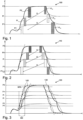
- figure 1 shows a diagram 100 with the course of a compressed air curve according to the prior art.
- Diagram 100 shows pressure curve P as a function of time t.
- the three columns on the right show the relief phases in which a relief pressure P Ex is released from the plastic containers.
- the pressure released in the first (upper) relief phase serves to pressurize a subsequent plastic container in the next lower pressure stage Pi and the pressure released in the second (middle) relief phase serves to pressurize the subsequent plastic container in pressure stage P1 .
- the blown air consumption of the subsequent container in the next lower pressure stage is preferably fed with the relief pressure of a preceding container of a higher pressure stage.
- New compressed air is (ideally) only supplied when the pressure P2 is applied. This compressed air then passes through the pressure stages in stages, in various containers and is then vented at the last container (lower relief phase).
- the third (lower) relief phase should be as small as possible with regard to the pressure and energy consumption, but it must also be higher than the pressure P1, since otherwise it would not be possible to recycle the air without an additional compression unit.
- figure 2 shows a diagram 110 with the course of a compressed air curve according to the device according to the invention/the method according to the invention. Unlike in the diagram of figure 1 there is a further additional intermediate stage here, in which the container is additionally subjected to the pressure P+.
- the reference symbol P1 base identifies the lowest pressure after the first increase in pressure when the pressure P1 is applied.
- figure 3 shows a diagram 120 with the profiles of the pressure curve according to the prior art 130 and according to the device according to the invention/the method 140 according to the invention in comparison. It can be seen that in the device according to the invention, the loading begins earlier and ends earlier, so that the forming process runs faster. At the same time, the container quality is improved by a longer holding time at the maximum pressure of the pressure P2.
- the time t90 characterizes the moment when the pressure P1 is applied until 90% of the pressure P2 is reached. This time should preferably be as short as possible.
- the Figures 4a and 4b show a schematic representation of a valve block 50 according to the prior art.
- the valve blocks 50 here have four or five process valves V1, Vi, V2, VEx . Due to the arrangement of the valves V1, Vi, V2, VEx , the dead space TR is relatively large here, which leads to a large installation space and a higher relief pressure.
- FIG. 1 shows a schematic representation of a valve block 50 according to the invention.
- the valve block 50 also has five valves V1, Vi, V+, V2, V Ex here, but in comparison to FIG Figure 4b an additional valve V+ for an additional intermediate stage.
- the dead space T R is also reduced due to the arrangement of the valves V1, Vi, V+, V2, V Ex .
- FIG 6 shows a schematic representation of an arrangement of a silencer 15 and a process valve V Ex according to the prior art.
- the V Ex valve is responsible for relieving the internal pressure in the tank, with the relieved air being fed to the environment through this valve and the downstream silencer.
- the muffler 15 and the valve V Ex are arranged on different sides of the valve body 52 of the valve block 50, so that the axes of the muffler 15 and the valve V Ex are at a 90° angle to one another.
- the compressed air must therefore be diverted, which in particular leads to a high flow path for the air.
- Reference number 12 denotes a control air supply for the valve.
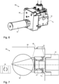
- FIG 7 shows a schematic representation of a first embodiment according to the invention of an arrangement of a silencer 15 and a process valve V Ex .
- the silencer 15 and the valve V Ex are arranged here on one axis or coaxially on the valve base body 52 of the valve block 50 .
- Such an arrangement in particular considerably shortens the flow path of the compressed air.
- the reference number 20 designates a valve seat or a sealing device, which is designed here by way of example as a flat-sealing soft seal
- the reference number 21 designates a valve piston, which is designed here as a hollow piston.
- the left representation of figure 7 shows an enlarged view of the outlet openings 18, which are designed here by way of example in the shape of a kidney.
- valve piston 21 and in particular the hollow piston is designed in this embodiment in such a way that it is actively kept closed via control air and opens when the pressure is relieved.
- the compressed air then flows through the kidney-shaped outlet openings 18 and the valve piston 21 into the silencer 15 and is fed to the environment via this.
- the process chamber 19 is closed against the outlet via the valve V Ex and a control air chamber (not shown) for the control air supply is pressurized, so that the valve V Ex is actively kept closed.
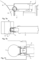
- Figure 7a shows a detailed representation of the in figure 7 Sealing device 20 shown.
- the sealing surface of this sealing device 20 is offset inwards, so that the valve is opened when the control pressure is relieved with the support of the pressure prevailing in the process chamber.
- the ratio of the sealing surfaces is designed in such a way that the valve can be held shut with control pressure.
- FIG. 7b shows a further schematic representation of the first embodiment according to the invention.
- the coaxial arrangement of the silencer 15 and the valve V Ex can be seen again in particular from this figure.
- the reference number 18 in turn designates the kidney-shaped outlet opening.
- Figure 7c shows a further schematic representation of the first embodiment according to the invention. This figure shows in particular the flow path marked by arrows of the air flow L from the valve V Ex to the silencer 15 when the valve V Ex is open.
- Figure 8a shows a schematic representation of a second embodiment according to the invention of an arrangement of a silencer 15 and a process valve V Ex .
- the silencer 15 and the process valve V Ex are again arranged coaxially to one another.
- the reference character L designates the air flow, illustrated by the arrows, from the valve V Ex into the silencer 15.
- valve piston 21 is not a hollow piston here, but an internally guided or internally centered piston, which is partially pressure-compensated.
- the valve piston 21 is opened again by the compressed air and is actively held closed with control pressure.
- FIG. 8b shows a further schematic representation of the second embodiment according to the invention.
- the kidney-shaped outlet opening 18 is also illustrated here again in the enlarged view on the right.
- figure 9 shows a schematic representation of a third embodiment according to the invention of an arrangement of a silencer 15 and a process valve V Ex .
- the silencer 15 is not arranged axially to the valve V Ex here, but is at an angle to it.
- the angle between the valve axis and the muffler axis is preferably less than 50°.
- figure 10 shows a schematic representation of an embodiment according to the invention of an arrangement of adjustable throttles 60, 62.
- Two throttles 60, 62 are arranged here, which can be displaced on a piston rod 70 along the arrows.
- either more or less air volume 69 of the air volume 68 present in the valve block 50 reaches the plastic container 10.
- the reference number 65 denotes a drive, such as a motor, by means of which the throttles 60, 62 can be displaced along the piston rod 70.
- the reference number 66 designates a compressed air supply line for the valve block 50.
- FIG 11 shows a schematic representation of a further embodiment according to the invention of an arrangement of adjustable throttles 60, 62.
- the arrangement corresponds to that in FIG figure 10 arrangement shown.
- the position of the throttles 60, 62 shown here is particularly advantageous for larger plastic preforms and plastic containers.
Landscapes
- Engineering & Computer Science (AREA)
- Manufacturing & Machinery (AREA)
- Mechanical Engineering (AREA)
- Life Sciences & Earth Sciences (AREA)
- Sustainable Development (AREA)
- Blow-Moulding Or Thermoforming Of Plastics Or The Like (AREA)
- Processing And Handling Of Plastics And Other Materials For Molding In General (AREA)
Applications Claiming Priority (1)
| Application Number | Priority Date | Filing Date | Title |
|---|---|---|---|
| DE102021128205.5A DE102021128205A1 (de) | 2021-10-28 | 2021-10-28 | Vorrichtung und Verfahren zum Umformen von Kunststoffvorformlingen zu Kunststoffbehältnissen mit verstellbarer Drossel |
Publications (2)
| Publication Number | Publication Date |
|---|---|
| EP4173797A1 true EP4173797A1 (fr) | 2023-05-03 |
| EP4173797B1 EP4173797B1 (fr) | 2024-08-21 |
Family
ID=84043857
Family Applications (1)
| Application Number | Title | Priority Date | Filing Date |
|---|---|---|---|
| EP22204151.9A Active EP4173797B1 (fr) | 2021-10-28 | 2022-10-27 | Dispositif et procédé de formage d'ébauches en plastique en récipients en plastique dotés d'un étranglement réglable |
Country Status (6)
| Country | Link |
|---|---|
| US (2) | US12403644B2 (fr) |
| EP (1) | EP4173797B1 (fr) |
| CN (1) | CN116039051B (fr) |
| DE (1) | DE102021128205A1 (fr) |
| ES (1) | ES2994856T3 (fr) |
| PL (1) | PL4173797T3 (fr) |
Cited By (1)
| Publication number | Priority date | Publication date | Assignee | Title |
|---|---|---|---|---|
| EP4173797B1 (fr) | 2021-10-28 | 2024-08-21 | Krones AG | Dispositif et procédé de formage d'ébauches en plastique en récipients en plastique dotés d'un étranglement réglable |
Families Citing this family (3)
| Publication number | Priority date | Publication date | Assignee | Title |
|---|---|---|---|---|
| DE102023114612A1 (de) * | 2023-06-02 | 2024-12-05 | Krones Aktiengesellschaft | Verfahren und Vorrichtung zum Umformen von Kunststoffvorformlingen zu Kunststoffbehältnissen mit vier Druckniveaus und Bodenkühlung |
| FR3150978B1 (fr) * | 2023-07-13 | 2025-06-06 | Sidel Participations | Procede de fabrication de corps creux avec recyclage du fluide de formage |
| DE102024102391A1 (de) * | 2024-01-29 | 2025-07-31 | Khs Gmbh | Blasvorrichtung zum Expandieren eines vorgeformten Hohlkörpers, Streckblasmaschine und Verfahren zum Expandieren eines Hohlkörpers |
Citations (6)
| Publication number | Priority date | Publication date | Assignee | Title |
|---|---|---|---|---|
| DE202004021477U1 (de) * | 2004-03-25 | 2008-04-24 | Krones Ag | Vorrichtung zum Herstellen eines insbesondere wärmebeständigen Hohlkörpers |
| US20080191394A1 (en) * | 2007-02-09 | 2008-08-14 | Ebac Limited | Blow moulding apparatus and method |
| EP1974892A2 (fr) * | 2007-03-29 | 2008-10-01 | Krones Aktiengesellschaft | Procédé destiné au moulage par soufflage |
| EP2298534A2 (fr) * | 2009-09-10 | 2011-03-23 | Krones AG | Procédé et dispositif destinés au moulage par soufflage de récipients |
| EP2722153A1 (fr) * | 2012-10-19 | 2014-04-23 | Krones AG | Machine et procédé de soufflage à niveau de pression intermédiaire variable |
| US10112337B2 (en) * | 2014-07-25 | 2018-10-30 | Khs Corpoplast Gmbh | Volume controlled blowing-air feed |
Family Cites Families (17)
| Publication number | Priority date | Publication date | Assignee | Title |
|---|---|---|---|---|
| US1087717A (en) | 1911-03-25 | 1914-02-17 | William A Brewster | Hot-water drum. |
| DE3815897C2 (de) * | 1988-05-10 | 1995-05-04 | Werner & Pfleiderer | Schneckenmaschine mit Anfahrventil und Drossel |
| DE202004021780U1 (de) | 2004-03-25 | 2010-12-09 | Krones Ag | Vorrichtung zum Herstellen eines insbesondere wärmebeständigen Hohlkörpers |
| DE202004018237U1 (de) | 2004-11-25 | 2005-02-24 | Festo Ag & Co. | Ventilanordnung |
| DE102009020738A1 (de) | 2009-05-11 | 2010-11-25 | Krones Ag | Vorrichtung zum Blasformen von Kunststoffvorformlingen mit reduziertem Totvolumen |
| JP5283668B2 (ja) * | 2010-08-09 | 2013-09-04 | アネスト岩田株式会社 | ブロー成形機 |
| DE102012010985A1 (de) | 2012-06-02 | 2013-12-05 | Krones Ag | Hohlkörperherstellungsmaschine |
| FR2997339B1 (fr) | 2012-10-29 | 2014-12-12 | Sidel Participations | Procede de soufflage de recipients avec un palier, et machine pour ce procede |
| WO2014068080A1 (fr) | 2012-11-01 | 2014-05-08 | Norgren Gmbh | Système de moulage par soufflage avec étirage comprenant actionnement simultané de valve de présoufflage |
| DE102013110132A1 (de) | 2013-09-13 | 2015-03-19 | Krones Ag | Vorrichtung und Verfahren zum Umformen von Kunststoffvorformlingen mit Blasluftrückgewinnung |
| US10046504B2 (en) | 2013-10-30 | 2018-08-14 | Norgren Ag | Fluid flow control device |
| US9796125B2 (en) * | 2014-01-07 | 2017-10-24 | Norgren Ag | Blowing cylinder |
| EP3418029A1 (fr) * | 2014-02-11 | 2018-12-26 | Norgren AG | Soupape de soufflage |
| JP6333577B2 (ja) * | 2014-02-28 | 2018-05-30 | 株式会社吉野工業所 | ブロー成形装置 |
| FR3088232B1 (fr) | 2018-11-08 | 2020-10-16 | Sidel Participations | Procede de fabrication d’un recipient en matiere plastique. |
| DE102019131188A1 (de) | 2019-11-19 | 2021-05-20 | Krones Aktiengesellschaft | Vorrichtung zum Umformen von Kunststoffvorformlingen zu Kunststoffbehältnissen mit Proportionalventil |
| DE102021128205A1 (de) | 2021-10-28 | 2023-05-04 | Krones Aktiengesellschaft | Vorrichtung und Verfahren zum Umformen von Kunststoffvorformlingen zu Kunststoffbehältnissen mit verstellbarer Drossel |
-
2021
- 2021-10-28 DE DE102021128205.5A patent/DE102021128205A1/de active Pending
-
2022
- 2022-09-12 US US17/942,999 patent/US12403644B2/en active Active
- 2022-10-27 EP EP22204151.9A patent/EP4173797B1/fr active Active
- 2022-10-27 ES ES22204151T patent/ES2994856T3/es active Active
- 2022-10-27 PL PL22204151.9T patent/PL4173797T3/pl unknown
- 2022-10-28 CN CN202211338636.8A patent/CN116039051B/zh active Active
-
2025
- 2025-07-18 US US19/274,183 patent/US20250345979A1/en active Pending
Patent Citations (6)
| Publication number | Priority date | Publication date | Assignee | Title |
|---|---|---|---|---|
| DE202004021477U1 (de) * | 2004-03-25 | 2008-04-24 | Krones Ag | Vorrichtung zum Herstellen eines insbesondere wärmebeständigen Hohlkörpers |
| US20080191394A1 (en) * | 2007-02-09 | 2008-08-14 | Ebac Limited | Blow moulding apparatus and method |
| EP1974892A2 (fr) * | 2007-03-29 | 2008-10-01 | Krones Aktiengesellschaft | Procédé destiné au moulage par soufflage |
| EP2298534A2 (fr) * | 2009-09-10 | 2011-03-23 | Krones AG | Procédé et dispositif destinés au moulage par soufflage de récipients |
| EP2722153A1 (fr) * | 2012-10-19 | 2014-04-23 | Krones AG | Machine et procédé de soufflage à niveau de pression intermédiaire variable |
| US10112337B2 (en) * | 2014-07-25 | 2018-10-30 | Khs Corpoplast Gmbh | Volume controlled blowing-air feed |
Cited By (1)
| Publication number | Priority date | Publication date | Assignee | Title |
|---|---|---|---|---|
| EP4173797B1 (fr) | 2021-10-28 | 2024-08-21 | Krones AG | Dispositif et procédé de formage d'ébauches en plastique en récipients en plastique dotés d'un étranglement réglable |
Also Published As
| Publication number | Publication date |
|---|---|
| EP4173797B1 (fr) | 2024-08-21 |
| DE102021128205A1 (de) | 2023-05-04 |
| CN116039051A (zh) | 2023-05-02 |
| US20230134386A1 (en) | 2023-05-04 |
| ES2994856T3 (en) | 2025-02-03 |
| US12403644B2 (en) | 2025-09-02 |
| US20250345979A1 (en) | 2025-11-13 |
| CN116039051B (zh) | 2025-09-09 |
| PL4173797T3 (pl) | 2025-01-07 |
Similar Documents
| Publication | Publication Date | Title |
|---|---|---|
| EP4173797B1 (fr) | Dispositif et procédé de formage d'ébauches en plastique en récipients en plastique dotés d'un étranglement réglable | |
| EP3645238B1 (fr) | Dispositif et procédé de compensation du temps de commutation sur un bloc de soupapes | |
| EP3825097B1 (fr) | Dispositif de formage des préformes en matière plastique pour obtenir des récipients en matière plastique pourvu de soupape proportionnelle | |
| DE102014115645A1 (de) | Verfahren und Vorrichtung zum Umformen von Kunststoffvorformlingen mit Querschnittsveränderung eines Volumenstroms | |
| WO2008080452A1 (fr) | Procédé de fabrication de récipients | |
| EP3109031A1 (fr) | Production de haute pression adiabatique | |
| EP2167303B1 (fr) | Dispositif de vannes pour machine de soufflage et procédé d'injection d'air sous pression dans une cavité de soufflage | |
| EP4470749A1 (fr) | Procédé et dispositif de formage d'ébauches en plastique en récipients en plastique dotés de quatre niveaux de pression et de refroidissement du fond | |
| EP2505336A1 (fr) | Dispositif d'entraînement pour la canne de soufflage d'une machine de formage par soufflage | |
| EP4082751B1 (fr) | Procédé de mise en oeuvre d'une unité de valves et unité de valves | |
| EP4082750B1 (fr) | Dispositif d'un système de soufflage | |
| EP3431252B1 (fr) | Dispositif de moulage par soufflage de récipients | |
| EP4164862B1 (fr) | Procédé de production de récipients à partir de préformes à l'aide d'un dispositif de production de récipients | |
| EP1466871B1 (fr) | Procédé et dispositif de commande du poinçon ébaucheur d'ume machine à façonner le verre | |
| EP4406725A2 (fr) | Dispositif de transformation d'ébauches en plastique en récipients en plastique dotés d'une soupape aseptique stérilisable | |
| EP4335616A1 (fr) | Procédé et dispositif de formage de préformes en matière plastique en récipients en matière plastique à l'aide d'une commande de pression de soufflage intermédiaire | |
| EP2735428A1 (fr) | Procédé d'étirage-soufflage et machine d'étirage-soufflage | |
| EP3793804B1 (fr) | Dispositif pour mouler des ébauches en matière plastique en récipients en matière plastique et moule de soufflage et procédé pour réaliser des récipients | |
| DE102022109817A1 (de) | Ventilblock | |
| DE102018105228A1 (de) | Vorrichtung und Verfahren zum Expandieren und gleichzeitigen Befüllen von Behältnissen | |
| DE102021128341B4 (de) | Verfahren zum Formen eines in eine Form einer Form- und Füllstation eingesetzten Vorformlings zu einem Behälter und Befüllen des sich formenden Behälters mit flüssigem Füllgut | |
| DE202023101385U1 (de) | Vorrichtung zum Umformen von Kunststoffvorformlingen zu Kunststoffbehältnissen mit verstellbarer Drossel | |
| DE102015211131A1 (de) | Verfahren und Blasmaschine zum Ausformen und Füllen von Behältern | |
| DE102014115372A1 (de) | Presseinrichtung für eine Glasformvorrichtung mit axial verschiebbarem Elektromotor | |
| DE102023115065A1 (de) | Vorrichtung und Verfahren zum Umformen von Kunststoffvorformlingen zu Kunststoffbehältnissen mit Proportionalventil |
Legal Events
| Date | Code | Title | Description |
|---|---|---|---|
| PUAI | Public reference made under article 153(3) epc to a published international application that has entered the european phase |
Free format text: ORIGINAL CODE: 0009012 |
|
| STAA | Information on the status of an ep patent application or granted ep patent |
Free format text: STATUS: THE APPLICATION HAS BEEN PUBLISHED |
|
| AK | Designated contracting states |
Kind code of ref document: A1 Designated state(s): AL AT BE BG CH CY CZ DE DK EE ES FI FR GB GR HR HU IE IS IT LI LT LU LV MC ME MK MT NL NO PL PT RO RS SE SI SK SM TR |
|
| STAA | Information on the status of an ep patent application or granted ep patent |
Free format text: STATUS: REQUEST FOR EXAMINATION WAS MADE |
|
| 17P | Request for examination filed |
Effective date: 20231005 |
|
| RBV | Designated contracting states (corrected) |
Designated state(s): AL AT BE BG CH CY CZ DE DK EE ES FI FR GB GR HR HU IE IS IT LI LT LU LV MC ME MK MT NL NO PL PT RO RS SE SI SK SM TR |
|
| GRAP | Despatch of communication of intention to grant a patent |
Free format text: ORIGINAL CODE: EPIDOSNIGR1 |
|
| STAA | Information on the status of an ep patent application or granted ep patent |
Free format text: STATUS: GRANT OF PATENT IS INTENDED |
|
| RIC1 | Information provided on ipc code assigned before grant |
Ipc: B29L 31/00 20060101ALN20240305BHEP Ipc: B29K 67/00 20060101ALN20240305BHEP Ipc: B29C 49/12 20060101ALN20240305BHEP Ipc: B29C 49/06 20060101ALN20240305BHEP Ipc: B29C 49/78 20060101ALI20240305BHEP Ipc: B29C 49/42 20060101AFI20240305BHEP |
|
| INTG | Intention to grant announced |
Effective date: 20240321 |
|
| GRAS | Grant fee paid |
Free format text: ORIGINAL CODE: EPIDOSNIGR3 |
|
| GRAA | (expected) grant |
Free format text: ORIGINAL CODE: 0009210 |
|
| STAA | Information on the status of an ep patent application or granted ep patent |
Free format text: STATUS: THE PATENT HAS BEEN GRANTED |
|
| AK | Designated contracting states |
Kind code of ref document: B1 Designated state(s): AL AT BE BG CH CY CZ DE DK EE ES FI FR GB GR HR HU IE IS IT LI LT LU LV MC ME MK MT NL NO PL PT RO RS SE SI SK SM TR |
|
| REG | Reference to a national code |
Ref country code: GB Ref legal event code: FG4D Free format text: NOT ENGLISH |
|
| REG | Reference to a national code |
Ref country code: CH Ref legal event code: EP |
|
| REG | Reference to a national code |
Ref country code: IE Ref legal event code: FG4D Free format text: LANGUAGE OF EP DOCUMENT: GERMAN |
|
| REG | Reference to a national code |
Ref country code: DE Ref legal event code: R096 Ref document number: 502022001504 Country of ref document: DE |
|
| REG | Reference to a national code |
Ref country code: LT Ref legal event code: MG9D |
|
| REG | Reference to a national code |
Ref country code: NL Ref legal event code: MP Effective date: 20240821 |
|
| PG25 | Lapsed in a contracting state [announced via postgrant information from national office to epo] |
Ref country code: NO Free format text: LAPSE BECAUSE OF FAILURE TO SUBMIT A TRANSLATION OF THE DESCRIPTION OR TO PAY THE FEE WITHIN THE PRESCRIBED TIME-LIMIT Effective date: 20241121 |
|
| PG25 | Lapsed in a contracting state [announced via postgrant information from national office to epo] |
Ref country code: NL Free format text: LAPSE BECAUSE OF FAILURE TO SUBMIT A TRANSLATION OF THE DESCRIPTION OR TO PAY THE FEE WITHIN THE PRESCRIBED TIME-LIMIT Effective date: 20240821 Ref country code: FI Free format text: LAPSE BECAUSE OF FAILURE TO SUBMIT A TRANSLATION OF THE DESCRIPTION OR TO PAY THE FEE WITHIN THE PRESCRIBED TIME-LIMIT Effective date: 20240821 Ref country code: GR Free format text: LAPSE BECAUSE OF FAILURE TO SUBMIT A TRANSLATION OF THE DESCRIPTION OR TO PAY THE FEE WITHIN THE PRESCRIBED TIME-LIMIT Effective date: 20241122 Ref country code: PT Free format text: LAPSE BECAUSE OF FAILURE TO SUBMIT A TRANSLATION OF THE DESCRIPTION OR TO PAY THE FEE WITHIN THE PRESCRIBED TIME-LIMIT Effective date: 20241223 |
|
| PG25 | Lapsed in a contracting state [announced via postgrant information from national office to epo] |
Ref country code: BG Free format text: LAPSE BECAUSE OF FAILURE TO SUBMIT A TRANSLATION OF THE DESCRIPTION OR TO PAY THE FEE WITHIN THE PRESCRIBED TIME-LIMIT Effective date: 20240821 |
|
| PG25 | Lapsed in a contracting state [announced via postgrant information from national office to epo] |
Ref country code: LV Free format text: LAPSE BECAUSE OF FAILURE TO SUBMIT A TRANSLATION OF THE DESCRIPTION OR TO PAY THE FEE WITHIN THE PRESCRIBED TIME-LIMIT Effective date: 20240821 |
|
| PG25 | Lapsed in a contracting state [announced via postgrant information from national office to epo] |
Ref country code: IS Free format text: LAPSE BECAUSE OF FAILURE TO SUBMIT A TRANSLATION OF THE DESCRIPTION OR TO PAY THE FEE WITHIN THE PRESCRIBED TIME-LIMIT Effective date: 20241221 |
|
| PG25 | Lapsed in a contracting state [announced via postgrant information from national office to epo] |
Ref country code: HR Free format text: LAPSE BECAUSE OF FAILURE TO SUBMIT A TRANSLATION OF THE DESCRIPTION OR TO PAY THE FEE WITHIN THE PRESCRIBED TIME-LIMIT Effective date: 20240821 |
|
| PG25 | Lapsed in a contracting state [announced via postgrant information from national office to epo] |
Ref country code: RS Free format text: LAPSE BECAUSE OF FAILURE TO SUBMIT A TRANSLATION OF THE DESCRIPTION OR TO PAY THE FEE WITHIN THE PRESCRIBED TIME-LIMIT Effective date: 20241121 |
|
| PG25 | Lapsed in a contracting state [announced via postgrant information from national office to epo] |
Ref country code: RS Free format text: LAPSE BECAUSE OF FAILURE TO SUBMIT A TRANSLATION OF THE DESCRIPTION OR TO PAY THE FEE WITHIN THE PRESCRIBED TIME-LIMIT Effective date: 20241121 Ref country code: PT Free format text: LAPSE BECAUSE OF FAILURE TO SUBMIT A TRANSLATION OF THE DESCRIPTION OR TO PAY THE FEE WITHIN THE PRESCRIBED TIME-LIMIT Effective date: 20241223 Ref country code: NO Free format text: LAPSE BECAUSE OF FAILURE TO SUBMIT A TRANSLATION OF THE DESCRIPTION OR TO PAY THE FEE WITHIN THE PRESCRIBED TIME-LIMIT Effective date: 20241121 Ref country code: NL Free format text: LAPSE BECAUSE OF FAILURE TO SUBMIT A TRANSLATION OF THE DESCRIPTION OR TO PAY THE FEE WITHIN THE PRESCRIBED TIME-LIMIT Effective date: 20240821 Ref country code: LV Free format text: LAPSE BECAUSE OF FAILURE TO SUBMIT A TRANSLATION OF THE DESCRIPTION OR TO PAY THE FEE WITHIN THE PRESCRIBED TIME-LIMIT Effective date: 20240821 Ref country code: IS Free format text: LAPSE BECAUSE OF FAILURE TO SUBMIT A TRANSLATION OF THE DESCRIPTION OR TO PAY THE FEE WITHIN THE PRESCRIBED TIME-LIMIT Effective date: 20241221 Ref country code: HR Free format text: LAPSE BECAUSE OF FAILURE TO SUBMIT A TRANSLATION OF THE DESCRIPTION OR TO PAY THE FEE WITHIN THE PRESCRIBED TIME-LIMIT Effective date: 20240821 Ref country code: GR Free format text: LAPSE BECAUSE OF FAILURE TO SUBMIT A TRANSLATION OF THE DESCRIPTION OR TO PAY THE FEE WITHIN THE PRESCRIBED TIME-LIMIT Effective date: 20241122 Ref country code: FI Free format text: LAPSE BECAUSE OF FAILURE TO SUBMIT A TRANSLATION OF THE DESCRIPTION OR TO PAY THE FEE WITHIN THE PRESCRIBED TIME-LIMIT Effective date: 20240821 Ref country code: BG Free format text: LAPSE BECAUSE OF FAILURE TO SUBMIT A TRANSLATION OF THE DESCRIPTION OR TO PAY THE FEE WITHIN THE PRESCRIBED TIME-LIMIT Effective date: 20240821 |
|
| REG | Reference to a national code |
Ref country code: ES Ref legal event code: FG2A Ref document number: 2994856 Country of ref document: ES Kind code of ref document: T3 Effective date: 20250203 |
|
| P01 | Opt-out of the competence of the unified patent court (upc) registered |
Free format text: CASE NUMBER: APP_1702/2025 Effective date: 20250110 |
|
| PG25 | Lapsed in a contracting state [announced via postgrant information from national office to epo] |
Ref country code: DK Free format text: LAPSE BECAUSE OF FAILURE TO SUBMIT A TRANSLATION OF THE DESCRIPTION OR TO PAY THE FEE WITHIN THE PRESCRIBED TIME-LIMIT Effective date: 20240821 Ref country code: SM Free format text: LAPSE BECAUSE OF FAILURE TO SUBMIT A TRANSLATION OF THE DESCRIPTION OR TO PAY THE FEE WITHIN THE PRESCRIBED TIME-LIMIT Effective date: 20240821 Ref country code: RO Free format text: LAPSE BECAUSE OF FAILURE TO SUBMIT A TRANSLATION OF THE DESCRIPTION OR TO PAY THE FEE WITHIN THE PRESCRIBED TIME-LIMIT Effective date: 20240821 |
|
| PG25 | Lapsed in a contracting state [announced via postgrant information from national office to epo] |
Ref country code: EE Free format text: LAPSE BECAUSE OF FAILURE TO SUBMIT A TRANSLATION OF THE DESCRIPTION OR TO PAY THE FEE WITHIN THE PRESCRIBED TIME-LIMIT Effective date: 20240821 |
|
| PG25 | Lapsed in a contracting state [announced via postgrant information from national office to epo] |
Ref country code: CZ Free format text: LAPSE BECAUSE OF FAILURE TO SUBMIT A TRANSLATION OF THE DESCRIPTION OR TO PAY THE FEE WITHIN THE PRESCRIBED TIME-LIMIT Effective date: 20240821 |
|
| PG25 | Lapsed in a contracting state [announced via postgrant information from national office to epo] |
Ref country code: SK Free format text: LAPSE BECAUSE OF FAILURE TO SUBMIT A TRANSLATION OF THE DESCRIPTION OR TO PAY THE FEE WITHIN THE PRESCRIBED TIME-LIMIT Effective date: 20240821 |
|
| REG | Reference to a national code |
Ref country code: DE Ref legal event code: R026 Ref document number: 502022001504 Country of ref document: DE |
|
| PLBI | Opposition filed |
Free format text: ORIGINAL CODE: 0009260 |
|
| PLAB | Opposition data, opponent's data or that of the opponent's representative modified |
Free format text: ORIGINAL CODE: 0009299OPPO |
|
| PLAX | Notice of opposition and request to file observation + time limit sent |
Free format text: ORIGINAL CODE: EPIDOSNOBS2 |
|
| 26 | Opposition filed |
Opponent name: KHS GMBH Effective date: 20250513 |
|
| R26 | Opposition filed (corrected) |
Opponent name: KHS GMBH Effective date: 20250513 |
|
| PG25 | Lapsed in a contracting state [announced via postgrant information from national office to epo] |
Ref country code: MC Free format text: LAPSE BECAUSE OF FAILURE TO SUBMIT A TRANSLATION OF THE DESCRIPTION OR TO PAY THE FEE WITHIN THE PRESCRIBED TIME-LIMIT Effective date: 20240821 |
|
| PG25 | Lapsed in a contracting state [announced via postgrant information from national office to epo] |
Ref country code: LU Free format text: LAPSE BECAUSE OF NON-PAYMENT OF DUE FEES Effective date: 20241027 Ref country code: BE Free format text: LAPSE BECAUSE OF NON-PAYMENT OF DUE FEES Effective date: 20241031 |
|
| REG | Reference to a national code |
Ref country code: BE Ref legal event code: MM Effective date: 20241031 |
|
| PG25 | Lapsed in a contracting state [announced via postgrant information from national office to epo] |
Ref country code: SE Free format text: LAPSE BECAUSE OF FAILURE TO SUBMIT A TRANSLATION OF THE DESCRIPTION OR TO PAY THE FEE WITHIN THE PRESCRIBED TIME-LIMIT Effective date: 20240821 |
|
| PLBB | Reply of patent proprietor to notice(s) of opposition received |
Free format text: ORIGINAL CODE: EPIDOSNOBS3 |
|
| PGFP | Annual fee paid to national office [announced via postgrant information from national office to epo] |
Ref country code: PL Payment date: 20250912 Year of fee payment: 4 |
|
| PGFP | Annual fee paid to national office [announced via postgrant information from national office to epo] |
Ref country code: FR Payment date: 20250908 Year of fee payment: 4 |
|
| PG25 | Lapsed in a contracting state [announced via postgrant information from national office to epo] |
Ref country code: IE Free format text: LAPSE BECAUSE OF NON-PAYMENT OF DUE FEES Effective date: 20241027 |
|
| REG | Reference to a national code |
Ref country code: CH Ref legal event code: U11 Free format text: ST27 STATUS EVENT CODE: U-0-0-U10-U11 (AS PROVIDED BY THE NATIONAL OFFICE) Effective date: 20251101 |
|
| PGFP | Annual fee paid to national office [announced via postgrant information from national office to epo] |
Ref country code: DE Payment date: 20250902 Year of fee payment: 4 |
|
| PGFP | Annual fee paid to national office [announced via postgrant information from national office to epo] |
Ref country code: AT Payment date: 20260113 Year of fee payment: 4 |
|
| PGFP | Annual fee paid to national office [announced via postgrant information from national office to epo] |
Ref country code: IT Payment date: 20251031 Year of fee payment: 4 |
|
| PGFP | Annual fee paid to national office [announced via postgrant information from national office to epo] |
Ref country code: CH Payment date: 20251101 Year of fee payment: 4 |
|
| PG25 | Lapsed in a contracting state [announced via postgrant information from national office to epo] |
Ref country code: CY Free format text: LAPSE BECAUSE OF FAILURE TO SUBMIT A TRANSLATION OF THE DESCRIPTION OR TO PAY THE FEE WITHIN THE PRESCRIBED TIME-LIMIT; INVALID AB INITIO Effective date: 20221027 |
|
| PGFP | Annual fee paid to national office [announced via postgrant information from national office to epo] |
Ref country code: ES Payment date: 20251104 Year of fee payment: 4 |
|
| PG25 | Lapsed in a contracting state [announced via postgrant information from national office to epo] |
Ref country code: HU Free format text: LAPSE BECAUSE OF FAILURE TO SUBMIT A TRANSLATION OF THE DESCRIPTION OR TO PAY THE FEE WITHIN THE PRESCRIBED TIME-LIMIT; INVALID AB INITIO Effective date: 20221027 |
|
| REG | Reference to a national code |
Ref country code: CH Ref legal event code: R17 Free format text: ST27 STATUS EVENT CODE: U-0-0-R10-R17 (AS PROVIDED BY THE NATIONAL OFFICE) Effective date: 20260410 |