EP4173870A1 - Console de commande - Google Patents
Console de commande Download PDFInfo
- Publication number
- EP4173870A1 EP4173870A1 EP22204481.0A EP22204481A EP4173870A1 EP 4173870 A1 EP4173870 A1 EP 4173870A1 EP 22204481 A EP22204481 A EP 22204481A EP 4173870 A1 EP4173870 A1 EP 4173870A1
- Authority
- EP
- European Patent Office
- Prior art keywords
- display
- area
- function
- operating console
- film
- Prior art date
- Legal status (The legal status is an assumption and is not a legal conclusion. Google has not performed a legal analysis and makes no representation as to the accuracy of the status listed.)
- Pending
Links
Images


Classifications
-
- B—PERFORMING OPERATIONS; TRANSPORTING
- B60—VEHICLES IN GENERAL
- B60K—ARRANGEMENT OR MOUNTING OF PROPULSION UNITS OR OF TRANSMISSIONS IN VEHICLES; ARRANGEMENT OR MOUNTING OF PLURAL DIVERSE PRIME-MOVERS IN VEHICLES; AUXILIARY DRIVES FOR VEHICLES; INSTRUMENTATION OR DASHBOARDS FOR VEHICLES; ARRANGEMENTS IN CONNECTION WITH COOLING, AIR INTAKE, GAS EXHAUST OR FUEL SUPPLY OF PROPULSION UNITS IN VEHICLES
- B60K35/00—Instruments specially adapted for vehicles; Arrangement of instruments in or on vehicles
- B60K35/10—Input arrangements, i.e. from user to vehicle, associated with vehicle functions or specially adapted therefor
-
- B—PERFORMING OPERATIONS; TRANSPORTING
- B60—VEHICLES IN GENERAL
- B60K—ARRANGEMENT OR MOUNTING OF PROPULSION UNITS OR OF TRANSMISSIONS IN VEHICLES; ARRANGEMENT OR MOUNTING OF PLURAL DIVERSE PRIME-MOVERS IN VEHICLES; AUXILIARY DRIVES FOR VEHICLES; INSTRUMENTATION OR DASHBOARDS FOR VEHICLES; ARRANGEMENTS IN CONNECTION WITH COOLING, AIR INTAKE, GAS EXHAUST OR FUEL SUPPLY OF PROPULSION UNITS IN VEHICLES
- B60K35/00—Instruments specially adapted for vehicles; Arrangement of instruments in or on vehicles
- B60K35/20—Output arrangements, i.e. from vehicle to user, associated with vehicle functions or specially adapted therefor
- B60K35/21—Output arrangements, i.e. from vehicle to user, associated with vehicle functions or specially adapted therefor using visual output, e.g. blinking lights or matrix displays
- B60K35/22—Display screens
-
- B—PERFORMING OPERATIONS; TRANSPORTING
- B60—VEHICLES IN GENERAL
- B60K—ARRANGEMENT OR MOUNTING OF PROPULSION UNITS OR OF TRANSMISSIONS IN VEHICLES; ARRANGEMENT OR MOUNTING OF PLURAL DIVERSE PRIME-MOVERS IN VEHICLES; AUXILIARY DRIVES FOR VEHICLES; INSTRUMENTATION OR DASHBOARDS FOR VEHICLES; ARRANGEMENTS IN CONNECTION WITH COOLING, AIR INTAKE, GAS EXHAUST OR FUEL SUPPLY OF PROPULSION UNITS IN VEHICLES
- B60K35/00—Instruments specially adapted for vehicles; Arrangement of instruments in or on vehicles
- B60K35/20—Output arrangements, i.e. from vehicle to user, associated with vehicle functions or specially adapted therefor
- B60K35/25—Output arrangements, i.e. from vehicle to user, associated with vehicle functions or specially adapted therefor using haptic output
-
- B—PERFORMING OPERATIONS; TRANSPORTING
- B60—VEHICLES IN GENERAL
- B60K—ARRANGEMENT OR MOUNTING OF PROPULSION UNITS OR OF TRANSMISSIONS IN VEHICLES; ARRANGEMENT OR MOUNTING OF PLURAL DIVERSE PRIME-MOVERS IN VEHICLES; AUXILIARY DRIVES FOR VEHICLES; INSTRUMENTATION OR DASHBOARDS FOR VEHICLES; ARRANGEMENTS IN CONNECTION WITH COOLING, AIR INTAKE, GAS EXHAUST OR FUEL SUPPLY OF PROPULSION UNITS IN VEHICLES
- B60K35/00—Instruments specially adapted for vehicles; Arrangement of instruments in or on vehicles
- B60K35/20—Output arrangements, i.e. from vehicle to user, associated with vehicle functions or specially adapted therefor
- B60K35/28—Output arrangements, i.e. from vehicle to user, associated with vehicle functions or specially adapted therefor characterised by the type of the output information, e.g. video entertainment or vehicle dynamics information; characterised by the purpose of the output information, e.g. for attracting the attention of the driver
-
- B—PERFORMING OPERATIONS; TRANSPORTING
- B60—VEHICLES IN GENERAL
- B60K—ARRANGEMENT OR MOUNTING OF PROPULSION UNITS OR OF TRANSMISSIONS IN VEHICLES; ARRANGEMENT OR MOUNTING OF PLURAL DIVERSE PRIME-MOVERS IN VEHICLES; AUXILIARY DRIVES FOR VEHICLES; INSTRUMENTATION OR DASHBOARDS FOR VEHICLES; ARRANGEMENTS IN CONNECTION WITH COOLING, AIR INTAKE, GAS EXHAUST OR FUEL SUPPLY OF PROPULSION UNITS IN VEHICLES
- B60K35/00—Instruments specially adapted for vehicles; Arrangement of instruments in or on vehicles
- B60K35/20—Output arrangements, i.e. from vehicle to user, associated with vehicle functions or specially adapted therefor
- B60K35/29—Instruments characterised by the way in which information is handled, e.g. showing information on plural displays or prioritising information according to driving conditions
-
- B—PERFORMING OPERATIONS; TRANSPORTING
- B60—VEHICLES IN GENERAL
- B60K—ARRANGEMENT OR MOUNTING OF PROPULSION UNITS OR OF TRANSMISSIONS IN VEHICLES; ARRANGEMENT OR MOUNTING OF PLURAL DIVERSE PRIME-MOVERS IN VEHICLES; AUXILIARY DRIVES FOR VEHICLES; INSTRUMENTATION OR DASHBOARDS FOR VEHICLES; ARRANGEMENTS IN CONNECTION WITH COOLING, AIR INTAKE, GAS EXHAUST OR FUEL SUPPLY OF PROPULSION UNITS IN VEHICLES
- B60K35/00—Instruments specially adapted for vehicles; Arrangement of instruments in or on vehicles
- B60K35/60—Instruments characterised by their location or relative disposition in or on vehicles
-
- G—PHYSICS
- G06—COMPUTING OR CALCULATING; COUNTING
- G06F—ELECTRIC DIGITAL DATA PROCESSING
- G06F3/00—Input arrangements for transferring data to be processed into a form capable of being handled by the computer; Output arrangements for transferring data from processing unit to output unit, e.g. interface arrangements
- G06F3/01—Input arrangements or combined input and output arrangements for interaction between user and computer
- G06F3/03—Arrangements for converting the position or the displacement of a member into a coded form
- G06F3/041—Digitisers, e.g. for touch screens or touch pads, characterised by the transducing means
- G06F3/045—Digitisers, e.g. for touch screens or touch pads, characterised by the transducing means using resistive elements, e.g. a single continuous surface or two parallel surfaces put in contact
-
- B—PERFORMING OPERATIONS; TRANSPORTING
- B60—VEHICLES IN GENERAL
- B60K—ARRANGEMENT OR MOUNTING OF PROPULSION UNITS OR OF TRANSMISSIONS IN VEHICLES; ARRANGEMENT OR MOUNTING OF PLURAL DIVERSE PRIME-MOVERS IN VEHICLES; AUXILIARY DRIVES FOR VEHICLES; INSTRUMENTATION OR DASHBOARDS FOR VEHICLES; ARRANGEMENTS IN CONNECTION WITH COOLING, AIR INTAKE, GAS EXHAUST OR FUEL SUPPLY OF PROPULSION UNITS IN VEHICLES
- B60K2360/00—Indexing scheme associated with groups B60K35/00 or B60K37/00 relating to details of instruments or dashboards
- B60K2360/11—Instrument graphical user interfaces or menu aspects
- B60K2360/111—Instrument graphical user interfaces or menu aspects for controlling multiple devices
-
- B—PERFORMING OPERATIONS; TRANSPORTING
- B60—VEHICLES IN GENERAL
- B60K—ARRANGEMENT OR MOUNTING OF PROPULSION UNITS OR OF TRANSMISSIONS IN VEHICLES; ARRANGEMENT OR MOUNTING OF PLURAL DIVERSE PRIME-MOVERS IN VEHICLES; AUXILIARY DRIVES FOR VEHICLES; INSTRUMENTATION OR DASHBOARDS FOR VEHICLES; ARRANGEMENTS IN CONNECTION WITH COOLING, AIR INTAKE, GAS EXHAUST OR FUEL SUPPLY OF PROPULSION UNITS IN VEHICLES
- B60K2360/00—Indexing scheme associated with groups B60K35/00 or B60K37/00 relating to details of instruments or dashboards
- B60K2360/11—Instrument graphical user interfaces or menu aspects
- B60K2360/115—Selection of menu items
-
- B—PERFORMING OPERATIONS; TRANSPORTING
- B60—VEHICLES IN GENERAL
- B60K—ARRANGEMENT OR MOUNTING OF PROPULSION UNITS OR OF TRANSMISSIONS IN VEHICLES; ARRANGEMENT OR MOUNTING OF PLURAL DIVERSE PRIME-MOVERS IN VEHICLES; AUXILIARY DRIVES FOR VEHICLES; INSTRUMENTATION OR DASHBOARDS FOR VEHICLES; ARRANGEMENTS IN CONNECTION WITH COOLING, AIR INTAKE, GAS EXHAUST OR FUEL SUPPLY OF PROPULSION UNITS IN VEHICLES
- B60K2360/00—Indexing scheme associated with groups B60K35/00 or B60K37/00 relating to details of instruments or dashboards
- B60K2360/11—Instrument graphical user interfaces or menu aspects
- B60K2360/119—Icons
-
- B—PERFORMING OPERATIONS; TRANSPORTING
- B60—VEHICLES IN GENERAL
- B60K—ARRANGEMENT OR MOUNTING OF PROPULSION UNITS OR OF TRANSMISSIONS IN VEHICLES; ARRANGEMENT OR MOUNTING OF PLURAL DIVERSE PRIME-MOVERS IN VEHICLES; AUXILIARY DRIVES FOR VEHICLES; INSTRUMENTATION OR DASHBOARDS FOR VEHICLES; ARRANGEMENTS IN CONNECTION WITH COOLING, AIR INTAKE, GAS EXHAUST OR FUEL SUPPLY OF PROPULSION UNITS IN VEHICLES
- B60K2360/00—Indexing scheme associated with groups B60K35/00 or B60K37/00 relating to details of instruments or dashboards
- B60K2360/128—Axially displaceable input devices for instruments
-
- B—PERFORMING OPERATIONS; TRANSPORTING
- B60—VEHICLES IN GENERAL
- B60K—ARRANGEMENT OR MOUNTING OF PROPULSION UNITS OR OF TRANSMISSIONS IN VEHICLES; ARRANGEMENT OR MOUNTING OF PLURAL DIVERSE PRIME-MOVERS IN VEHICLES; AUXILIARY DRIVES FOR VEHICLES; INSTRUMENTATION OR DASHBOARDS FOR VEHICLES; ARRANGEMENTS IN CONNECTION WITH COOLING, AIR INTAKE, GAS EXHAUST OR FUEL SUPPLY OF PROPULSION UNITS IN VEHICLES
- B60K2360/00—Indexing scheme associated with groups B60K35/00 or B60K37/00 relating to details of instruments or dashboards
- B60K2360/143—Touch sensitive instrument input devices
- B60K2360/1438—Touch screens
-
- B—PERFORMING OPERATIONS; TRANSPORTING
- B60—VEHICLES IN GENERAL
- B60K—ARRANGEMENT OR MOUNTING OF PROPULSION UNITS OR OF TRANSMISSIONS IN VEHICLES; ARRANGEMENT OR MOUNTING OF PLURAL DIVERSE PRIME-MOVERS IN VEHICLES; AUXILIARY DRIVES FOR VEHICLES; INSTRUMENTATION OR DASHBOARDS FOR VEHICLES; ARRANGEMENTS IN CONNECTION WITH COOLING, AIR INTAKE, GAS EXHAUST OR FUEL SUPPLY OF PROPULSION UNITS IN VEHICLES
- B60K2360/00—Indexing scheme associated with groups B60K35/00 or B60K37/00 relating to details of instruments or dashboards
- B60K2360/143—Touch sensitive instrument input devices
- B60K2360/1438—Touch screens
- B60K2360/1442—Emulation of input devices
-
- B—PERFORMING OPERATIONS; TRANSPORTING
- B60—VEHICLES IN GENERAL
- B60K—ARRANGEMENT OR MOUNTING OF PROPULSION UNITS OR OF TRANSMISSIONS IN VEHICLES; ARRANGEMENT OR MOUNTING OF PLURAL DIVERSE PRIME-MOVERS IN VEHICLES; AUXILIARY DRIVES FOR VEHICLES; INSTRUMENTATION OR DASHBOARDS FOR VEHICLES; ARRANGEMENTS IN CONNECTION WITH COOLING, AIR INTAKE, GAS EXHAUST OR FUEL SUPPLY OF PROPULSION UNITS IN VEHICLES
- B60K2360/00—Indexing scheme associated with groups B60K35/00 or B60K37/00 relating to details of instruments or dashboards
- B60K2360/145—Instrument input by combination of touch screen and hardware input devices
-
- B—PERFORMING OPERATIONS; TRANSPORTING
- B60—VEHICLES IN GENERAL
- B60K—ARRANGEMENT OR MOUNTING OF PROPULSION UNITS OR OF TRANSMISSIONS IN VEHICLES; ARRANGEMENT OR MOUNTING OF PLURAL DIVERSE PRIME-MOVERS IN VEHICLES; AUXILIARY DRIVES FOR VEHICLES; INSTRUMENTATION OR DASHBOARDS FOR VEHICLES; ARRANGEMENTS IN CONNECTION WITH COOLING, AIR INTAKE, GAS EXHAUST OR FUEL SUPPLY OF PROPULSION UNITS IN VEHICLES
- B60K2360/00—Indexing scheme associated with groups B60K35/00 or B60K37/00 relating to details of instruments or dashboards
- B60K2360/1523—Matrix displays
-
- B—PERFORMING OPERATIONS; TRANSPORTING
- B60—VEHICLES IN GENERAL
- B60K—ARRANGEMENT OR MOUNTING OF PROPULSION UNITS OR OF TRANSMISSIONS IN VEHICLES; ARRANGEMENT OR MOUNTING OF PLURAL DIVERSE PRIME-MOVERS IN VEHICLES; AUXILIARY DRIVES FOR VEHICLES; INSTRUMENTATION OR DASHBOARDS FOR VEHICLES; ARRANGEMENTS IN CONNECTION WITH COOLING, AIR INTAKE, GAS EXHAUST OR FUEL SUPPLY OF PROPULSION UNITS IN VEHICLES
- B60K2360/00—Indexing scheme associated with groups B60K35/00 or B60K37/00 relating to details of instruments or dashboards
- B60K2360/16—Type of output information
- B60K2360/178—Warnings
-
- B—PERFORMING OPERATIONS; TRANSPORTING
- B60—VEHICLES IN GENERAL
- B60K—ARRANGEMENT OR MOUNTING OF PROPULSION UNITS OR OF TRANSMISSIONS IN VEHICLES; ARRANGEMENT OR MOUNTING OF PLURAL DIVERSE PRIME-MOVERS IN VEHICLES; AUXILIARY DRIVES FOR VEHICLES; INSTRUMENTATION OR DASHBOARDS FOR VEHICLES; ARRANGEMENTS IN CONNECTION WITH COOLING, AIR INTAKE, GAS EXHAUST OR FUEL SUPPLY OF PROPULSION UNITS IN VEHICLES
- B60K2360/00—Indexing scheme associated with groups B60K35/00 or B60K37/00 relating to details of instruments or dashboards
- B60K2360/18—Information management
- B60K2360/188—Displaying information using colour changes
-
- B—PERFORMING OPERATIONS; TRANSPORTING
- B60—VEHICLES IN GENERAL
- B60K—ARRANGEMENT OR MOUNTING OF PROPULSION UNITS OR OF TRANSMISSIONS IN VEHICLES; ARRANGEMENT OR MOUNTING OF PLURAL DIVERSE PRIME-MOVERS IN VEHICLES; AUXILIARY DRIVES FOR VEHICLES; INSTRUMENTATION OR DASHBOARDS FOR VEHICLES; ARRANGEMENTS IN CONNECTION WITH COOLING, AIR INTAKE, GAS EXHAUST OR FUEL SUPPLY OF PROPULSION UNITS IN VEHICLES
- B60K2360/00—Indexing scheme associated with groups B60K35/00 or B60K37/00 relating to details of instruments or dashboards
- B60K2360/18—Information management
- B60K2360/199—Information management for avoiding maloperation
-
- B—PERFORMING OPERATIONS; TRANSPORTING
- B60—VEHICLES IN GENERAL
- B60K—ARRANGEMENT OR MOUNTING OF PROPULSION UNITS OR OF TRANSMISSIONS IN VEHICLES; ARRANGEMENT OR MOUNTING OF PLURAL DIVERSE PRIME-MOVERS IN VEHICLES; AUXILIARY DRIVES FOR VEHICLES; INSTRUMENTATION OR DASHBOARDS FOR VEHICLES; ARRANGEMENTS IN CONNECTION WITH COOLING, AIR INTAKE, GAS EXHAUST OR FUEL SUPPLY OF PROPULSION UNITS IN VEHICLES
- B60K2360/00—Indexing scheme associated with groups B60K35/00 or B60K37/00 relating to details of instruments or dashboards
- B60K2360/20—Optical features of instruments
-
- B—PERFORMING OPERATIONS; TRANSPORTING
- B60—VEHICLES IN GENERAL
- B60Y—INDEXING SCHEME RELATING TO ASPECTS CROSS-CUTTING VEHICLE TECHNOLOGY
- B60Y2200/00—Type of vehicle
- B60Y2200/40—Special vehicles
- B60Y2200/41—Construction vehicles, e.g. graders, excavators
Definitions
- the present invention relates to a control console with a touch screen for operating a device, in particular for operating a device connected to a vehicle.
- operating devices In order to operate devices, in particular on vehicles, for example construction vehicles or water cannon vehicles, operating devices are usually used, by means of which device functions of the respective device can be controlled.
- Operating devices of this type which are also known as operating consoles, have a number of buttons which can be actuated by an operator to control the device functions assigned to the buttons.
- buttons For the operation of complex machines, there is the possibility of designing the buttons in the form of numerous keys with their own printing and thus a defined function.
- the disadvantage of such keys with a defined function is that a large number of keys are required in order to cover all the necessary functions, in particular if a wide variety of operating modes that require different operating functions are to be covered by means of the operating console. If an operating mode is only rarely used, the relevant keys, which are only relevant for this operating mode, are largely useless.
- Such operating modes can relate, for example, to a set-up operation, a transport trip and/or a working mode of the device or of the vehicle in question.
- touch displays In order to reduce the number of keys and thus the size of the control panel of the control console, it is known to use touch displays on which changing functions can be defined using variable icons.
- the disadvantage of such touch displays is that they are not suitable for robust working environments. Dirt on capacitive displays can lead to unwanted effects. Even resistive touch displays are not always easy to use, especially when wearing work gloves. Even when working in the dark, touch displays are not ideal, despite the possibility of an illuminated night design. It is therefore the object of the present invention to create a control console which avoids the aforementioned disadvantages of known control consoles.
- an operating console which has a display which is designed as a resistive touch display and accordingly has a touch surface.
- a film is arranged over the touch surface, which film covers, preferably completely covers, the touch surface and has at least one function key, preferably a plurality of function keys.
- the function keys have a transparent or at least translucent see-through area in a more opaque environment, through which the display can be visually perceived. The transparency should be as high as possible, and because 100% transparency is almost impossible, a translucency of 90% or more is considered transparent for the purposes of the present invention.
- the function key has a bulge portion that extends in a direction away from the touch surface.
- This bulge area is tactile and preferably extends at least one millimeter across an outer surface of the film.
- the bulge area is used so that the user can not only find the function key blindly and grasp it tactilely, but can also press against the touch surface of the resistive touch display and thus activate the function key.
- a controller is also provided that is set up to show the user a function of the relevant function key for one or more of the function keys by means of the display through the respective transparent area, which function varies depending on an individual specification.
- a control console designed in this way is particularly suitable for operating a device that can be operated in different operating modes.
- the case is the individual specification on which the function displayed in the transparent area of the relevant function key depends, the specific operating mode in which the device to be operated by means of the operating console is or should be operated.
- the operating console is preferably designed in such a way that the user himself can choose between a plurality of operating modes using the operating console.
- a control console designed in this way can be used advantageously in the same way if the control console is not (or not only) used to operate a device in different operating modes, but is (also) operated with different menu types.
- the individual specification on which the function displayed in the view-through area of the relevant function key depends is the specific menu type with which the operating console is operated.
- Such menu types can be, for example, a settings menu, service menu, operating menu and/or other menu.
- the control panel combines compactness and ease of use with low manufacturing costs.
- the compactness is achieved by the fact that function keys are assigned a different function depending on the selected operating mode, so that they are basically multifunction keys.
- the number of function keys can be kept small in this way.
- the ease of use of the control console is due to the fact that the curved areas of the function keys can be felt tactilely, so that they can be found even in poor light conditions or without looking.
- the more opaque environment compared to the see-through area makes it easier to find the see-through area and thus to find the relevant function key.
- the control console can be produced inexpensively because a conventional resistive touch display can be used, over the touch surface of which the film containing the function keys is attached. For example, the film can be glued onto the touch display in a simple manner.
- the control console is robust in several respects, because on the one hand a conventional, robust resistive touch display can be used and on the other hand because the film also protects this touch display from dirt and other environmental influences.
- the resistive touch display offers the advantage that it only triggers when the touch surface is actively (slightly) pressed.
- the bulge area can also be formed by a partial area of the film that thickens toward the outside.
- a cavity in the bulge area offers the advantage that the user gets a better feedback feeling because he has to press the button deeper and with the necessary minimum pressure and thus experiences a more intensive pressure experience.
- the curvature with the cavity underneath can be achieved in a simple and inexpensive manner by embossing, in particular by hot embossing.
- the film itself can have a thickness of between 100 ⁇ m and 400 ⁇ m, preferably about 200 ⁇ m. This applies in particular to the bulge area if there is a cavity under the bulge area, the specific thickness being chosen depending on the material of the film so that pressing down the bulge area does not require too much force, but is also not unintentional.
- the film is preferably a plastic film, with polyester having proven to be particularly suitable for the film material.
- the foil can also be a silicone foil and in this way form a non-slip silicone keyboard.
- the silicone film can be relatively thick and have a mat-like shape.
- the silicone film or silicone mat can also be additionally provided over the actual plastic film.
- the operating console can advantageously have one or more additional function keys which are structured in the same way as the multifunction keys but are independent of the operating mode. This means that with these function keys, the respective function that is independent of the operating mode is always shown in the same way by means of the display through the transparent area of the function key, regardless of the selected operating mode.
- Fixed function keys can also be printed with a fixed symbol in the foil.
- the environment that is more opaque than the see-through area is completely opaque, that is to say non-transparent.
- This can be implemented in a simple and correspondingly inexpensive manner by means of an opaque, preferably black or gray, coating on the upper side of the film or, particularly preferably, on the underside of the film.
- Coating the underside of the foil has the advantage that the opaque imprint cannot wear off through normal operation.
- Coating the upper side of the film has the advantage that, particularly when using a matte coating, the unprinted see-through areas are particularly easy to identify.
- the top of the film can be matted outside of the see-through areas.
- a transparent or at least translucent status window can also be provided in the opaque area around the function key, for example in the form of a small circular or polygonal see-through area, with the controller being set up in this regard to use the display to show a color code in the status window, which varies depending on the status .
- the see-through area is preferably created in such a way that the opaque coating on the film in the area of the status window is missing, or by the status window being cut out of the film.
- the color code shown in the status window by means of the display can preferably be generated with 8 bits per color channel, ie can vary with up to 16.8 million colors. In particular, the color code can vary between three colors, for example green, red and yellow, or only between two colors or between two or more of these and/or other colors if the display under the status window lights up in a corresponding color.
- green can stand for an on, inactive state, yellow for an on, active state, red for a critical state and no lighting for an off state.
- Other codings are of course possible.
- the status of the function key can also be generated by the color of the icon or the background color of the icon.
- the opaque environment not only surrounds the see-through area of a function key and, if present, an associated status window, but surrounds multiple see-through areas (and status windows). This means that several function keys are arranged in an opaque area.
- one or more transparent or at least translucent display windows can be provided in the opaque environment, with the controller being set up with regard to the display window to display any information in the display window using the display.
- the display need not be touch sensitive in the area of the display window, although this is not excluded.
- the resistive touch display can include a conventional TFT display as the display device.
- other display devices can also be used, for example a glass-glass touch display.
- the resistive touch sensor is arranged above the display device of the touch display, which, for example, can have two PET films with an ITO coating arranged one on top of the other in a conventional manner.
- the two PET foils are slightly spaced apart and are pressed together by pressing the function keys so that the respective ITO coatings come into contact with one another and trigger a corresponding signal.
- the transparent areas of the function keys are preferably free of electrically conductive structures.
- the pressure sensitivity of resistive touch displays can vary over the distance between the contact points to be brought into contact with each other.
- the operating modes of the device to be controlled using the control panel can be very different.
- the operating modes can be set-up operation, transport travel, work mode, etc.
- the function of one or more of the function keys includes a security function.
- the safety function button can only be activated when a second button is pressed simultaneously or sequentially.
- the second key can be another function key on the foil of the touch display or a standard key.
- the second button is also preferably tactilely perceptible to the user.
- the control console 1 shows a control console 1 according to a preferred embodiment schematically in plan view.
- the control console 1 includes a frame 2 in which a display 3 is accommodated.
- the display 3 with a plurality of function keys 4, a display window 5 for displaying any information and further, static display fields 6 and 7, which here have the shape of an on/off switch and a warning icon.
- the area of the function keys 4 and the display window 5 information can be displayed for the user by means of the display, whereas the surroundings 8 of these areas 4, 5 and the display fields 6 and 7 are printed in opaque, preferably black or grey.
- the printing ink is preferably matt so that the display window 5 and in particular the function keys 4 stand out visually from the surroundings 8 .
- each function key 4 (alternatively only one or individual keys) is assigned a status window 9, which is also transparent or at least translucent.
- the status windows 9 are circular here, but can assume any shape. They are used to indicate the current status of the function that is displayed on the display 3 in the area of the associated function key 4, for example by a green or red or possibly also a yellow light, with other colors such as blue being possible .
- green can mean that the function displayed in the area of the relevant function key 4 is switched on but is inactive
- red means that the function is critical
- yellow can mean that the function is switched on and also active.
- the function keys 4 thus each include a transparent see-through area that 1 marked 4a.
- the display has an upward, i.e. outwardly directed, curvature 4b for each of the function keys 4, which can be felt tactilely and can be pressed downwards or backwards by the user in order to generate a signal via the display. which is related to the relevant function of the function key 4, for example, the relevant function off or on.
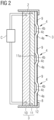
- the display 3 is a touch display, specifically a resistive touch display, as shown below using the schematic cross section through the display 3 according to FIG 2 is explained.
- the display 3 consists of two layers 10 and 11 accommodated in the frame 2.
- the bottom layer 10 is the display device of the resistive touch display 3, which is a TFT display, for example.
- the person skilled in the art is familiar with other display devices that can be used as an alternative to the TFT display.
- a touch sensor as layer 11.
- capacitive and resistive touch sensors for touch displays where the touch sensor layer 11 is a resistive touch sensor.
- the structure of resistive touch sensors is well known and essentially comprises two slightly spaced layers, for example PET films, each with internal conductor track structures which, when they come into contact with one another under the influence of external pressure, generate a corresponding signal.
- the conductor track structures are so fine that they do not disturb the view of the display device underneath.
- They can be embodied in an ITO coating.
- the TFT display layer 10 and the touch sensor layer 11 are each connected to a controller C, which on the one hand registers the signals from the touch layer 11 and on the other hand generates the information to be displayed by means of the TFT display layer 10 .
- a transparent film in which the previously described function keys 4 are formed.
- the film is preferably a polyester film.
- the function keys 4 include on the one hand a transparent area 4a and a curved area 4b.
- the opaque environment 8, which delimits the see-through areas 4a, is formed by an opaque imprint on the outside of the transparent film 12. FIG. Alternatively, this imprint can also be present on the inner surface of the transparent film 12 . Instead of imprinting the opaque surroundings 8, a different coating method can also be selected. In the area of the status window 9 assigned to the function keys 4 , the opaque area 8 is also cut out, so that the TFT display layer 10 can be seen through the status window 9 , the transparent film 12 and the touch sensor layer 11 .
- the bulging areas 4b of the transparent film 12 are preferably embossed and particularly preferably produced using the hot embossing process.
- a silicone material can also be used, which dispenses with the cavity. This material can be used in combination with the polyester film or as a pure silicone mat.
- a cavity 4c is thus formed below each bulge area 4b. Accordingly, a user operates the function keys 4 by pressing the bulge portion 4b against a touch surface 11a of the touch sensor layer 11 so as to electrically short-circuit the corresponding location in the touch-sensing layer 11 and generate a corresponding signal which is processed by the controller C. Due to the inherent elasticity of the film 12, it automatically moves back into the arched starting position after the switching process.
- the thickness of the film 12, at least in the bulge area 4b is preferably between 100 ⁇ m and 400 ⁇ m, for example 200 ⁇ m.
- the two upper rows of function keys are independent of the operating mode. This means that the function assigned to the relevant function key 4 is indicated by means of the display through the respective transparent area 4a on the two in Figures 3 and 4 shown operating modes are displayed immediately. This is different for the three function keys 4 in the lower row of function keys.
- the function keys 4 depend on the respective operating mode of the device to be controlled. In the operating mode according to 3 Therefore, different information is displayed in the corresponding see-through areas 4a by means of the underlying display, namely in the form of icons or symbols, than in the operating mode according to FIG 4 .
- the respective status of the function is displayed, which belongs to the relevant function key 4.
- a red status indicator is in the Figures 3 and 4 For example, rendered black, a green status indicator gray, and no status indicator white.
- the status window 9 has between the Figures 3 and 4 only the status display of the upper right status window 9 changed from white (no function in this operating mode) to yellow (active and operational).
- the warning panel 7 is clearly red (shown in black), and a fuel pump symbol is shown in the display window 5, making it clear to the user that the warning panel is lit due to a low fuel level.
- the display window 5 can display any other information. It can also be designed as a touch display.
- the on/off switch in the display field 6 can also be designed as a touch display, so that when the touch display is switched on, i.e. in which the touch function of the display window is live, touching the on/off switch causes the device to switch to a standby mode would cause. In this case, it is expedient to form the transparent film 12 with a bulge area 4b in this display panel 6 as well.
- the touch display in contrast to what is shown here, can also be set up so that the user can use it to switch between different operating modes of the device to be controlled with it.
Landscapes
- Engineering & Computer Science (AREA)
- Chemical & Material Sciences (AREA)
- Combustion & Propulsion (AREA)
- Transportation (AREA)
- Mechanical Engineering (AREA)
- General Engineering & Computer Science (AREA)
- Theoretical Computer Science (AREA)
- Human Computer Interaction (AREA)
- Physics & Mathematics (AREA)
- General Physics & Mathematics (AREA)
- Push-Button Switches (AREA)
Applications Claiming Priority (1)
| Application Number | Priority Date | Filing Date | Title |
|---|---|---|---|
| DE102021128470.8A DE102021128470B4 (de) | 2021-11-02 | 2021-11-02 | Bedienkonsole |
Publications (1)
| Publication Number | Publication Date |
|---|---|
| EP4173870A1 true EP4173870A1 (fr) | 2023-05-03 |
Family
ID=84044582
Family Applications (1)
| Application Number | Title | Priority Date | Filing Date |
|---|---|---|---|
| EP22204481.0A Pending EP4173870A1 (fr) | 2021-11-02 | 2022-10-28 | Console de commande |
Country Status (3)
| Country | Link |
|---|---|
| US (1) | US20230136384A1 (fr) |
| EP (1) | EP4173870A1 (fr) |
| DE (1) | DE102021128470B4 (fr) |
Families Citing this family (3)
| Publication number | Priority date | Publication date | Assignee | Title |
|---|---|---|---|---|
| IT202300015822A1 (it) | 2023-07-27 | 2025-01-27 | Tt Group S R L | Consolle di comando per sale di controllo |
| DE102024208070A1 (de) * | 2024-08-23 | 2026-02-26 | BSH Hausgeräte GmbH | Haushaltsgerät-Bedienvorrichtung mit großflächigem Display und davor angeordnetem opakem Blendenelement mit mehreren zumindest transluzenten Bereichen, sowie Haushaltsgerät |
| DE202024106341U1 (de) * | 2024-11-06 | 2026-04-16 | GETT Gerätetechnik GmbH | Tastenmodul für Panel-PCs und eine daraus gebildete Tastenmodul-Panel-PC-Einheit |
Citations (4)
| Publication number | Priority date | Publication date | Assignee | Title |
|---|---|---|---|---|
| US20050024342A1 (en) * | 2003-07-31 | 2005-02-03 | Sarah Young | Display device |
| US20110267274A1 (en) * | 2009-01-13 | 2011-11-03 | Igal Shusteri | Keypad |
| DE102015100344A1 (de) * | 2015-01-12 | 2016-07-14 | Emporia Telecom Gmbh & Co Kg | Tastatur, Hülle und mobiles Endgerät mit einer solchen Tastatur sowie Ladestation für ein mobiles Endgerät |
| US20170168634A1 (en) * | 2014-01-30 | 2017-06-15 | Lucian Cristian Depold | Operating aid for a touch-sensitive display |
Family Cites Families (10)
| Publication number | Priority date | Publication date | Assignee | Title |
|---|---|---|---|---|
| US20050088417A1 (en) * | 2003-10-24 | 2005-04-28 | Mulligan Roger C. | Tactile touch-sensing system |
| US8564538B2 (en) * | 2008-10-21 | 2013-10-22 | Belkin International, Inc. | Touch screen overlays and methods for manufacturing the same |
| US8421761B2 (en) | 2009-08-26 | 2013-04-16 | General Electric Company | Imaging multi-modality touch pad interface systems, methods, articles of manufacture, and apparatus |
| US8206047B1 (en) * | 2011-06-24 | 2012-06-26 | TouchFire, Inc. | Keyboard overlay for optimal touch typing on a proximity-based touch screen |
| US20130044058A1 (en) * | 2011-08-19 | 2013-02-21 | Korry Electronics Co. | Reconfigurable fixed function, nbc compatible integrated display system |
| US9575628B2 (en) * | 2013-03-29 | 2017-02-21 | Deere & Company | Icon featured touch screen display system including status shortcuts for a work vehicle and method of managing the same |
| US11092732B2 (en) * | 2015-12-18 | 2021-08-17 | Harman International Industries, Incorporates | Lens system and method |
| US20160110001A1 (en) * | 2015-12-28 | 2016-04-21 | Caterpillar Inc. | Interactive display system |
| DE102017131264A1 (de) * | 2017-12-22 | 2019-06-27 | Liebherr-Hydraulikbagger Gmbh | Baumaschine, insbesondere Erdbewegungsmaschine mit einem Bedienpult |
| US10494772B1 (en) * | 2018-05-10 | 2019-12-03 | Caterpillar Sarl | Control system for a paving machine |
-
2021
- 2021-11-02 DE DE102021128470.8A patent/DE102021128470B4/de active Active
-
2022
- 2022-10-28 EP EP22204481.0A patent/EP4173870A1/fr active Pending
- 2022-11-02 US US17/979,503 patent/US20230136384A1/en not_active Abandoned
Patent Citations (4)
| Publication number | Priority date | Publication date | Assignee | Title |
|---|---|---|---|---|
| US20050024342A1 (en) * | 2003-07-31 | 2005-02-03 | Sarah Young | Display device |
| US20110267274A1 (en) * | 2009-01-13 | 2011-11-03 | Igal Shusteri | Keypad |
| US20170168634A1 (en) * | 2014-01-30 | 2017-06-15 | Lucian Cristian Depold | Operating aid for a touch-sensitive display |
| DE102015100344A1 (de) * | 2015-01-12 | 2016-07-14 | Emporia Telecom Gmbh & Co Kg | Tastatur, Hülle und mobiles Endgerät mit einer solchen Tastatur sowie Ladestation für ein mobiles Endgerät |
Also Published As
| Publication number | Publication date |
|---|---|
| DE102021128470B4 (de) | 2024-02-29 |
| US20230136384A1 (en) | 2023-05-04 |
| DE102021128470A1 (de) | 2023-05-04 |
Similar Documents
| Publication | Publication Date | Title |
|---|---|---|
| DE102021128470B4 (de) | Bedienkonsole | |
| DE60212490T2 (de) | Leuchtendes Touch-Pad | |
| DE102011119896B4 (de) | Schaltervorrichtung | |
| DE102013009563B4 (de) | Landwirtschaftliche Maschine | |
| DE3124625A1 (de) | Schalteranordnung, insbesondere tastenfeld mit beschriftungstraeger | |
| EP4077049B1 (fr) | Unité d'actionnement pour un véhicule à moteur | |
| DE102017218243B3 (de) | Verfahren zum Herstellen zumindest eines Teils einer berührungssensitiven Bedieneinrichtung, berührungssensitive Bedieneinrichtung und Kraftfahrzeug | |
| DE102008036155B4 (de) | Bedientastenanordnung | |
| DE102011000899A1 (de) | Eingabevorrichtung | |
| DE102007005882A1 (de) | Anzeige und Bedienungsschalter mit entsprechender Anzeige | |
| DE202012103075U1 (de) | Bedienflächenelement, Bedieneinheit und Gerät | |
| DE69509425T2 (de) | Bedienungstafel für elektronische Vorrichtungen | |
| EP0597467B1 (fr) | Panel de contrÔle pour un appareil de traitement dentaire | |
| DE10142031A1 (de) | Anzeige- und Eingabevorrichtung | |
| LU85611A1 (fr) | Schalter/anzeige-einheiten | |
| DE10350252A1 (de) | Kombination aus Touchscreen und Membranschalter | |
| DE20007972U1 (de) | Berührungsempfindlicher Bildschirm | |
| DE202023102992U1 (de) | Bedienelement für einen Fahrzeuginnenraum | |
| DE102015113694B4 (de) | Kapazitives Bedienelement mit verbesserter Störunanfälligkeit | |
| EP3435205B1 (fr) | Feuille pourvue de couche fonctionnelle et de réponse haptique | |
| DE102020122189A1 (de) | Zierteil mit einstückiger aus Festsilikonen gebildeter Multifunktionsschicht | |
| DE102025114041A1 (de) | Touchscreen mit Fühlleiste | |
| DE4222940A1 (de) | Tastatur mit Maus-Eingabefeld | |
| DE102015225310B3 (de) | Vorrichtung zum Erfassen von Eingaben eines Nutzers in einem Fahrzeug und Fahrzeug | |
| WO2003103256A1 (fr) | Dispositif d'affichage a possibilite d'entree |
Legal Events
| Date | Code | Title | Description |
|---|---|---|---|
| PUAI | Public reference made under article 153(3) epc to a published international application that has entered the european phase |
Free format text: ORIGINAL CODE: 0009012 |
|
| STAA | Information on the status of an ep patent application or granted ep patent |
Free format text: STATUS: THE APPLICATION HAS BEEN PUBLISHED |
|
| AK | Designated contracting states |
Kind code of ref document: A1 Designated state(s): AL AT BE BG CH CY CZ DE DK EE ES FI FR GB GR HR HU IE IS IT LI LT LU LV MC ME MK MT NL NO PL PT RO RS SE SI SK SM TR |
|
| STAA | Information on the status of an ep patent application or granted ep patent |
Free format text: STATUS: REQUEST FOR EXAMINATION WAS MADE |
|
| 17P | Request for examination filed |
Effective date: 20230616 |
|
| RBV | Designated contracting states (corrected) |
Designated state(s): AL AT BE BG CH CY CZ DE DK EE ES FI FR GB GR HR HU IE IS IT LI LT LU LV MC ME MK MT NL NO PL PT RO RS SE SI SK SM TR |