EP4173909B1 - Dispositif de soupape pour système de véhicule et système pour véhicule - Google Patents
Dispositif de soupape pour système de véhicule et système pour véhicule Download PDFInfo
- Publication number
- EP4173909B1 EP4173909B1 EP22201977.0A EP22201977A EP4173909B1 EP 4173909 B1 EP4173909 B1 EP 4173909B1 EP 22201977 A EP22201977 A EP 22201977A EP 4173909 B1 EP4173909 B1 EP 4173909B1
- Authority
- EP
- European Patent Office
- Prior art keywords
- actuator
- electrical
- terminal
- supply
- valve
- Prior art date
- Legal status (The legal status is an assumption and is not a legal conclusion. Google has not performed a legal analysis and makes no representation as to the accuracy of the status listed.)
- Active
Links
Images

Classifications
-
- B—PERFORMING OPERATIONS; TRANSPORTING
- B60—VEHICLES IN GENERAL
- B60T—VEHICLE BRAKE CONTROL SYSTEMS OR PARTS THEREOF; BRAKE CONTROL SYSTEMS OR PARTS THEREOF, IN GENERAL; ARRANGEMENT OF BRAKING ELEMENTS ON VEHICLES IN GENERAL; PORTABLE DEVICES FOR PREVENTING UNWANTED MOVEMENT OF VEHICLES; VEHICLE MODIFICATIONS TO FACILITATE COOLING OF BRAKES
- B60T15/00—Construction arrangement, or operation of valves incorporated in power brake systems and not covered by groups B60T11/00 or B60T13/00
- B60T15/02—Application and release valves
- B60T15/025—Electrically controlled valves
- B60T15/027—Electrically controlled valves in pneumatic systems
-
- B—PERFORMING OPERATIONS; TRANSPORTING
- B60—VEHICLES IN GENERAL
- B60T—VEHICLE BRAKE CONTROL SYSTEMS OR PARTS THEREOF; BRAKE CONTROL SYSTEMS OR PARTS THEREOF, IN GENERAL; ARRANGEMENT OF BRAKING ELEMENTS ON VEHICLES IN GENERAL; PORTABLE DEVICES FOR PREVENTING UNWANTED MOVEMENT OF VEHICLES; VEHICLE MODIFICATIONS TO FACILITATE COOLING OF BRAKES
- B60T13/00—Transmitting braking action from initiating means to ultimate brake actuator with power assistance or drive; Brake systems incorporating such transmitting means, e.g. air-pressure brake systems
- B60T13/10—Transmitting braking action from initiating means to ultimate brake actuator with power assistance or drive; Brake systems incorporating such transmitting means, e.g. air-pressure brake systems with fluid assistance, drive, or release
- B60T13/66—Electrical control in fluid-pressure brake systems
- B60T13/68—Electrical control in fluid-pressure brake systems by electrically-controlled valves
-
- B—PERFORMING OPERATIONS; TRANSPORTING
- B60—VEHICLES IN GENERAL
- B60W—CONJOINT CONTROL OF VEHICLE SUB-UNITS OF DIFFERENT TYPE OR DIFFERENT FUNCTION; CONTROL SYSTEMS SPECIALLY ADAPTED FOR HYBRID VEHICLES; ROAD VEHICLE DRIVE CONTROL SYSTEMS FOR PURPOSES NOT RELATED TO THE CONTROL OF A PARTICULAR SUB-UNIT
- B60W50/00—Details of control systems for road vehicle drive control not related to the control of a particular sub-unit, e.g. process diagnostic or vehicle driver interfaces
- B60W50/02—Ensuring safety in case of control system failures, e.g. by diagnosing, circumventing or fixing failures
- B60W50/023—Avoiding failures by using redundant parts
-
- F—MECHANICAL ENGINEERING; LIGHTING; HEATING; WEAPONS; BLASTING
- F16—ENGINEERING ELEMENTS AND UNITS; GENERAL MEASURES FOR PRODUCING AND MAINTAINING EFFECTIVE FUNCTIONING OF MACHINES OR INSTALLATIONS; THERMAL INSULATION IN GENERAL
- F16K—VALVES; TAPS; COCKS; ACTUATING-FLOATS; DEVICES FOR VENTING OR AERATING
- F16K31/00—Actuating devices; Operating means; Releasing devices
- F16K31/02—Actuating devices; Operating means; Releasing devices electric; magnetic
Definitions
- the present invention relates to a valve device for a system for a vehicle and to a system for a vehicle, in particular an electronic braking system.
- redundancies must be created. These redundancies must be designed in such a way that the vehicle cannot end up in a safety-critical or uncontrollable state.
- systems such as the electric braking system EBS or ABS are being placed multiple times in the vehicle.
- Another possibility may be to supplement the system with similar subsystems that can map the functionality.
- the faulty system can be switched off and the second fault-free system can take over the task, thus creating redundancy.
- the number of pressure control valves on each axle and each wheel would be doubled.
- valve device for a system for a vehicle and by a system for a vehicle according to the main claims.
- a protected pressure control valve for dual use or multiple use can be provided for a redundant vehicle system, for example a vehicle brake system.
- electrical protection circuits each of which has an electrical Safety device and a diode element can be integrated into the pressure control valve.
- a pressure control valve in particular can be used by two control units in a manner that is electrically protected by means of the safety devices in order to provide redundancy in the system.
- a cost-effective multiple system can be provided in particular, whereby duplication of pressure control valves can be avoided.
- This not only saves costs but also installation space and effort for wiring, so that such a valve device for a system can be easily integrated into the vehicle.
- Integrating the protective circuits, each of which is designed, for example, as a combination of fuse and diode, into a valve, in particular a pressure control valve has the advantage that vehicle wiring is made easier when used twice.
- Y-cables which can be susceptible to corrosion, can be dispensed with.
- the vehicle can be a motor vehicle, in particular a commercial vehicle, for example a truck or the like.
- the system can be designed, for example, as an electronic braking system or electropneumatic braking system or other braking system or other vehicle system.
- the first control unit can be a primary control unit, wherein the second control unit can be a redundant control unit.
- the first control unit can be assigned to a first function or assistance function of the vehicle or the system, wherein the second control unit can be assigned to a second function or assistance function of the vehicle or the system.
- the device can be designed as a pressure control valve.
- the valve unit and thus the valve device can have at least one solenoid valve.
- the actuator can comprise a resistive inductance.
- the diode element can have a diode, a semiconductor diode or the like.
- the safety device can have a fuse or other electrical fuse.
- the actuator can be connected to a first electrical supply potential of the first control device via the first supply connection.
- the actuator can be connected to a second electrical supply potential of the second control device via the second supply connection.
- the actuator can also be connected to an electrical supply potential of the first control device via the first supply connection. wherein the actuator can be connected to the electrical supply potential of the second control device via the second supply connection, wherein the actuator can be connected to a first electrical ground potential via a first main connection and to a second electrical ground potential of the control devices via the second main connection.
- the actuator can be connected to a common electrical ground potential of the control devices via the first main connection and the second main connection.
- the diode element of the first protective circuit can also be connected between the first supply connection and the actuator.
- the safety device of the first protective circuit can be connected between the second supply connection and the actuator.
- the safety device of the second protective circuit can be connected between the actuator and the first main connection.
- the diode element of the second protective circuit can be connected between the actuator and the second main connection.
- a forward direction of the diode element of the first protective circuit can run from the first supply connection to the actuator.
- a forward direction of the diode element of the second protective circuit can run from the actuator to the second main connection.
- valve unit can have at least one further actuator for actuating the valve unit.
- the valve device can have at least one third supply connection for electrically connecting the further actuator to the first control unit, at least one fourth supply connection for electrically connecting the further actuator to the second control unit and at least one have a further protective circuit.
- the further protective circuit can be electrically connected between the third supply connection and the fourth supply connection on the one hand and the further actuator on the other hand.
- the second protective circuit can be electrically connected between the further actuator on the one hand and the first main connection and the second main connection on the other hand.
- the actuator of the valve unit can be part of an inlet valve of the valve device, for example, and the further actuator can be part of an outlet valve of the valve device, for example. Such an embodiment offers the advantage that any number of actuators of the valve device can be protected with minimal effort.
- the diode element of the further protective circuit can be connected between the third supply connection and the further actuator.
- the safety device of the further protective circuit can be connected between the fourth supply connection and the further actuator.
- a forward direction of the diode element of the further protective circuit can also run from the third supply connection to the further actuator.
- the additional actuator can be connected to the first electrical supply potential via the third supply connection.
- the additional actuator can be connected to the second electrical supply potential via the fourth supply connection.
- the safety devices of the protective circuits can also be arranged in the protective circuits in an exchangeable manner. Such an embodiment offers the advantage that after a fault has occurred, a simple and cost-effective replacement of one or more safety devices can be done to restore the functionality of the protective circuits.
- the valve device can be connected or can be connected to the first control unit and to the second control unit by means of electrical lines.
- the system can also have at least one further valve device.
- the valve device can also have a first group of mechanically combined electrical connections for connecting the first control device and a second group of mechanically combined electrical connections for connecting the second control device.
- One plug goes to the first control device, the other to the second control device. Loosening of a plug does not lead to a failure of the functionality of the system.
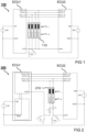
- Fig.1 shows a schematic representation of a system 100.
- the system is, for example, a braking system.
- Several electronic control units, here the first control unit ECU1 and the second control unit ECU2, for braking control use common pressure control valves with the actuators 110 in order to represent redundancy in the system 100.
- the first control unit ECU1 comprises connections PCV1_IV, PCV1_OV, PCV2_IV, PCV2_OV and GVR1 for electrical connection to the actuators 110 and connections UB1 and GND1 for connection to a first electrical voltage source.
- the second control unit ECU2 comprises connections PCV1_IV, PCV1_OV, PCV2_IV, PCV2_OV and GVR1 for electrical connection to the actuators 110 and connections UB2 and GND1 for connection to a second electrical voltage source.
- a short circuit from UB1 to the jointly used actuator ground is also shown as an example.
- a state can arise in which neither the first control unit ECU1 nor the second control unit ECU2 can control the actuators 110. If there is a short circuit from UB1 or UB2 to the jointly used actuator ground, control is no longer possible.
- Another possible error case is the closure of the control to UB1 or UB2.
- ABS control for example, is therefore not possible from either the first control unit ECU1 or the second control unit ECU2. Full redundancy of a primary braking system may therefore not be possible under certain circumstances.
- Fig. 2 shows a schematic representation of a system 200.
- the system 200 in Fig. 2 corresponds to the system of Fig.1 with the exception that only one pressure control valve with two actuators 210 is provided, with a fuse F and a diode D additionally being provided to protect the pressure control valve.
- Several Electronic control units here the first control unit ECU1 and the second control unit ECU2, use a common pressure control valve for brake control, which has the two actuators 210, in order to provide redundancy in the system 200.
- the fuse F should trigger and thus disconnect the ground line GVR1, which is subject to a short circuit.
- the diode D should protect the ECU2 in the event of a short circuit of UB1 on the side of the second control unit. In both cases, the short circuit can also be triggered with UB2.
- Fig.3 shows a schematic representation of a vehicle 300 with a system 305 according to an embodiment.
- the system 305 can be the system of Fig.2
- the system 305 includes a first controller 310, a second controller 320, and a valve device 330.
- the controllers 310 and 320 are electrically connected to the valve device 330.
- the valve device 330 is discussed in more detail below.
- Fig.4 shows a schematic representation of an embodiment of a valve device 330 for a system.
- the system corresponds or is similar to the system from Fig.3 .
- the system comprises a first control device and a second control device which are electrically connectable or connected to the valve device 330.
- the valve device 330 corresponds to or is similar to the valve device of Fig.3 .
- the valve device 330 is designed as a pressure control valve (PCV) for the system.
- PCV pressure control valve
- the valve device 330 includes a valve unit 450, a first supply port 441, a second supply port 442, a first main port 445, a second main port 446, a first electrical protection circuit 460, a second electrical protection circuit 470, and a valve housing 435.
- the valve housing 435 is shaped to accommodate the valve unit 450 and the protection circuits 460 and 470.
- the valve unit 450 is designed to adjust a pressure of a working medium for the system.
- the valve unit 450 comprises at least one actuator 452 for Actuating the valve unit 450.
- the valve unit 450 is arranged within the valve housing 435.
- the at least one actuator 452 comprises a resistive inductance, as shown in the illustration of Fig.4 is illustrated by an equivalent circuit with an inductance L and a resistance R.
- the first supply connection 441 is used to electrically connect the actuator 452 to the first control unit of the system.
- the second supply connection 442 is used to electrically connect the actuator 452 to the second control unit of the system.
- the first main connection 445 is used to electrically connect the actuator 452 to the first control unit.
- the second main connection 446 is used to electrically connect the actuator 452 to the second control unit.
- the first protection circuit 460 and the second protection circuit 470 are arranged within the valve housing 435.
- the first protection circuit 460 is electrically connected between the first supply connection 441 and the second supply connection 442 on the one hand and the actuator 452 on the other hand.
- the first protection circuit 460 comprises an electrical fuse device 462 and a diode element 464, which are inserted in series into the respective supply/ground connection.
- the second protection circuit 470 is electrically connected between the actuator 452 on the one hand and the first main connection 445 and the second main connection 446 on the other hand.
- the second protection circuit 470 comprises an electrical fuse device 472 and a diode element 474, which are inserted in series into the respective supply/ground connection.
- the safety devices 462 and 472 are designed to trigger in the event of an electrical fault in the system, for example in the event of a short circuit, and to separate the faulty supply/ground path.
- the diode elements 464 and 474 are also designed to prevent impermissible current flow in such a fault event.
- the diode element 464 of the first protection circuit 460 is connected between the first supply connection 441 and the actuator 452. Furthermore, the safety device 462 of the first protection circuit 460 is connected between the second supply connection 442 and the actuator 452. In addition, the safety device 472 of the second Protection circuit 470 is connected between the actuator 452 and the first main connection 445. The diode element 474 of the second protection circuit 470 is also connected between the actuator 452 and the second main connection 446. For example, a forward direction of the diode element 464 of the first protection circuit 460 runs from the first supply connection 441 to the actuator 452. Furthermore, for example, a forward direction of the diode element 474 of the second protection circuit 470 runs from the actuator 452 to the second main connection 464.
- the actuator 452 can be connected to a first electrical supply potential of the first control unit via the first supply connection 441 and can be connected to a second electrical supply potential of the second control unit via the second supply connection 442. Furthermore, the actuator 452 can be connected to a common electrical ground potential of the control units via each of the ground connections 445 and 446.
- the valve unit 450 comprises at least one further actuator 454 for actuating the valve unit 450.
- the valve device 330 also comprises at least one third supply connection 443 for electrically connecting the further actuator 454 to the first control unit, at least one fourth supply connection 444 for electrically connecting the further actuator 454 to the second control unit, and at least one further electrical protection circuit 480.
- the further protection circuit 480 also comprises an electrical fuse device 482 and a diode element 484, which are inserted in series into the respective supply/ground connection.
- the further protection circuit 480 is electrically connected between the third supply connection 443 and the fourth supply connection 444 on the one hand and the further actuator 454 on the other hand.
- the second protection circuit 470 is also electrically connected between the further actuator 454 on the one hand and the ground connections 445 and 446 on the other. More precisely, the diode element 484 of the further protective circuit 480 is connected between the third supply connection 443 and the further actuator 454, wherein the safety device 482 of the further protective circuit 480 is connected between the fourth supply connection 444 and the further actuator 454.
- the further actuator 454 can be connected to the first electrical supply potential via the third supply connection 443 and can be connected to the second electrical supply potential via the fourth supply connection 444. Furthermore, the further actuator 454 can be connected to a common electrical ground potential of the control units via each of the ground connections 445 and 446.
- the pressure control valve or the valve device 330 comprises, for example, an inlet valve which has the actuator 452 and an outlet valve which has the further actuator 454, wherein the actuators 452 and 454 can be connected or are connected to a common ground. Control lines or supply lines are routed separately from the control units to the actuators 452 and 454.
- the safety devices 462, 472 and optionally 482 of the protective circuits 460, 470 and optionally 480 are arranged so as to be replaceable in the protective circuits 460, 470 and optionally 480.
- each of the safety devices 462, 472 and optionally 482 can be individually replaced or renewed if necessary.
- the error source mentioned can thus be created by the protective circuits 460, 470 and optionally 480, which are advantageously integrated into the pressure control valve or the valve device 330, more precisely arranged within the valve housing 435, in order to avoid further error sources.
- the first control unit 310 (equivalent to the first control unit ECU1) can transfer control of the valve device 330 to the second control unit 320 (equivalent to the second control unit ECU2) without restriction.
- the first control unit 310 can control the valve device 330 or its actuator 452 or actuators 452 without restriction. and 454.
- the integration of the protective circuits 460, 470 and optionally 480 can thus also be incorporated into a control path for the valve device 330.
Landscapes
- Engineering & Computer Science (AREA)
- Mechanical Engineering (AREA)
- Transportation (AREA)
- General Engineering & Computer Science (AREA)
- Automation & Control Theory (AREA)
- Human Computer Interaction (AREA)
- Regulating Braking Force (AREA)
- Valves And Accessory Devices For Braking Systems (AREA)
- Magnetically Actuated Valves (AREA)
Claims (11)
- Dispositif de soupape (330) pour un système (305) pour un véhicule (300), dans lequel le système (305) présente un premier appareil de commande (310) et un second appareil de commande (320), dans lequel les appareils de commande (310, 320) peuvent être connectés électriquement au dispositif de soupape (330), dans lequel le dispositif de soupape (330) présente les caractéristiques suivantes :une unité de soupape (450) destinée au réglage d'une pression d'un fluide de travail pour le système (305), dans lequel l'unité de soupape (450) présente au moins un actionneur (452) destiné à l'actionnement de l'unité de soupape (450) ;une première borne d'alimentation (441) destinée à la liaison électrique de l'actionneur (452) au premier appareil de commande (310), une deuxième borne d'alimentation (442) destiné à la liaison électrique de l'actionneur (452) au second appareil de commande (320), une première borne principale (445) destinée à la connexion électrique de l'actionneur (452) au premier appareil de commande (310) et une seconde borne principale (446) destinée à la connexion électrique de l'actionneur (452) au second appareil de commande (320) ;un premier circuit de protection électrique (460) et un second circuit de protection électrique (470), dans lequel le premier circuit de protection (460) est commuté électriquement entre la première borne d'alimentation (441) et la deuxième borne d'alimentation (442) d'une part et l'actionneur (452) d'autre part, dans lequel le second circuit de protection (470) est commuté électriquement entre l'actionneur (452) d'une part et la première borne principale (445) et la seconde borne principale (446) d'autre part, dans lequel chaque circuit de protection (460, 470) présente un équipement de sécurité électrique (462, 472) et un élément de diode (464, 474) qui sont insérés en série dans au moins les première (441) et/ou deuxième (442) bornes d'alimentation ou au moins la première (445) et/ou la seconde (446) borne principale ; etun boîtier de soupape(435) destiné à la réception de l'unité de soupape (450) et des circuits de protection (460, 470).
- Dispositif de soupape (330) selon la revendication 1, dans lequel l'actionneur (452) peut être raccordé à un premier potentiel d'alimentation électrique du premier appareil de commande (310) par le biais de la première borne d'alimentation (441), dans lequel l'actionneur (452) peut être raccordé à un second potentiel d'alimentation électrique du second appareil de commande (320) par le biais de la deuxième borne d'alimentation (442), dans lequel l'actionneur (452) peut être raccordé à un potentiel de masse électrique commun des appareils de commande (310, 320) par le biais de la première borne principale (445) et de la seconde borne principale (446) et/ou dans lequel l'actionneur (452) peut être raccordé à un potentiel d'alimentation électrique du premier appareil de commande (310) par le biais de la première borne d'alimentation (441), dans lequel l'actionneur (452) peut être raccordé à un potentiel d'alimentation électrique du second appareil de commande (320) par le biais de la deuxième borne d'alimentation (442), dans lequel l'actionneur (452) peut être raccordé à un premier potentiel de masse électrique par le biais de la première borne principale (445) et à un second potentiel de masse électrique des appareils de commande (310, 320) par le biais de la seconde borne principale (446).
- Dispositif de soupape (330) selon l'une quelconque des revendications précédentes, dans lequel la première borne d'alimentation (441) et la deuxième borne d'alimentation (442) sont une borne de tension d'alimentation et la première (445) et la seconde (446) bornes principales sont une borne de masse ou dans lequel la première borne d'alimentation (441) et la deuxième borne d'alimentation (442) sont une borne de masse et la première (445) et la seconde (446) bornes principales sont une borne de tension d'alimentation.
- Dispositif de soupape (330) selon l'une quelconque des revendications précédentes, dans lequel l'élément de diode (464) du premier circuit de protection (460) est commuté entre la première borne d'alimentation (441) et l'actionneur (452), dans lequel l'équipement de sécurité (462) du premier circuit de protection (460) est commuté entre la deuxième borne d'alimentation (442) et l'actionneur (452), dans lequel l'équipement de sécurité (472) du second circuit de protection (470) est commuté entre l'actionneur (452) et la première borne principale (445), dans lequel l'élément de diode (474) du second circuit de protection (470) est commuté entre l'actionneur (452) et la seconde borne principale (446).
- Dispositif de soupape (330) selon l'une quelconque des revendications précédentes, dans lequel un sens passant de l'élément de diode (464) du premier circuit de protection (460) s'étend de la première borne d'alimentation (441) à l'actionneur (452), dans lequel un sens passant de l'élément de diode (474) du second circuit de protection (470) s'étend de l'actionneur (452) à la seconde borne principale (446).
- Dispositif de soupape(330) selon l'une quelconque des revendications précédentes, dans lequel l'unité de soupape (450) présente au moins un actionneur supplémentaire (454) destiné à l'actionnement de l'unité de soupape (450), dans lequel le dispositif de soupape (330) présente au moins une troisième borne d'alimentation (443) destinée à la connexion électrique de l'actionneur supplémentaire (454) au premier appareil de commande (310), au moins une quatrième borne d'alimentation (444) destinée à la connexion électrique de l'actionneur supplémentaire 454) au second appareil de commande (320) et au moins un circuit de protection supplémentaire (480), dans lequel le circuit de protection supplémentaire (480) est commuté électriquement entre la troisième borne d'alimentation (443) et la quatrième borne d'alimentation (444) d'une part et l'actionneur supplémentaire (454) d'autre part, dans lequel le second circuit de protection (470) est commuté électriquement entre l'actionneur supplémentaire (454) d'une part et la première borne principale (445) et la seconde borne principale (446) d'autre part.
- Dispositif de soupape (330) selon la revendication 6, dans lequel l'élément de diode (484) du circuit de protection supplémentaire (480) est commuté entre la troisième borne d'alimentation (443) et l'actionneur supplémentaire (454), dans lequel l'équipement de sécurité (482) du circuit de protection supplémentaire (480) est commuté entre la quatrième borne d'alimentation (444) et l'actionneur supplémentaire (454).
- Dispositif de soupape (330) selon l'une quelconque des revendications 6 à 7, dans lequel l'actionneur supplémentaire (454) peut être raccordé au premier potentiel d'alimentation électrique par le biais de la troisième borne d'alimentation (443), dans lequel l'actionneur supplémentaire (454) peut être raccordé au second potentiel d'alimentation électrique par le biais de la quatrième borne d'alimentation (444).
- Dispositif de soupape (330) selon l'une quelconque des revendications précédentes, dans lequel les équipements de sécurité (462, 472, 482) des circuits de protection (460, 470, 480) sont disposés dans les circuits de protection (460, 470, 480) de manière interchangeable.
- Système (305) pour un véhicule (300), dans lequel le système (305) présente les caractéristiques suivantes :un dispositif de soupape (330) selon l'une quelconque des revendications précédentes ; etle premier appareil de commande (310) et le second appareil de commande (320), dans lequel les appareils de commande (310, 320) sont reliés électriquement au dispositif de soupape (330).
- Système (305) selon la revendication 10, dans lequel le dispositif de soupape (330) présente un premier groupe de bornes électriques réunies mécaniquement destinées au raccordement du premier appareil de commande (310) et un second groupe de bornes électriques réunies mécaniquement destinées au raccordement du second appareil de commande (320).
Applications Claiming Priority (1)
| Application Number | Priority Date | Filing Date | Title |
|---|---|---|---|
| DE102021127909.7A DE102021127909A1 (de) | 2021-10-27 | 2021-10-27 | Ventilvorrichtung für ein System für ein Fahrzeug und System für ein Fahrzeug |
Publications (2)
| Publication Number | Publication Date |
|---|---|
| EP4173909A1 EP4173909A1 (fr) | 2023-05-03 |
| EP4173909B1 true EP4173909B1 (fr) | 2024-09-18 |
Family
ID=83898440
Family Applications (1)
| Application Number | Title | Priority Date | Filing Date |
|---|---|---|---|
| EP22201977.0A Active EP4173909B1 (fr) | 2021-10-27 | 2022-10-17 | Dispositif de soupape pour système de véhicule et système pour véhicule |
Country Status (4)
| Country | Link |
|---|---|
| US (1) | US12606140B2 (fr) |
| EP (1) | EP4173909B1 (fr) |
| CN (1) | CN116022114B (fr) |
| DE (1) | DE102021127909A1 (fr) |
Families Citing this family (1)
| Publication number | Priority date | Publication date | Assignee | Title |
|---|---|---|---|---|
| DE102021127910A1 (de) * | 2021-10-27 | 2023-04-27 | Knorr-Bremse Systeme für Nutzfahrzeuge GmbH | Ventilvorrichtung für ein System, insbesondere ein für ein Fahrzeug und System, insbesondere Bremssystem für ein Fahrzeug |
Family Cites Families (10)
| Publication number | Priority date | Publication date | Assignee | Title |
|---|---|---|---|---|
| DE2938344A1 (de) * | 1979-09-21 | 1981-04-09 | Knorr-Bremse GmbH, 8000 München | Sicherheitsschaltung zur uebewachung von magnetventilen von fahrzeugen |
| KR101441041B1 (ko) * | 2008-10-20 | 2014-09-18 | 현대모비스 주식회사 | 솔레노이드 밸브의 제어장치 |
| DE102018103605A1 (de) * | 2018-02-19 | 2019-08-22 | Knorr-Bremse Systeme für Nutzfahrzeuge GmbH | Elektropneumatische Ausrüstung eines Fahrzeugs |
| DE102018121957B4 (de) * | 2018-09-10 | 2026-02-12 | Knorr-Bremse Systeme für Nutzfahrzeuge GmbH | Schutzvorrichtung zur Entkopplung elektrischer Steuerkreise in einem redundanten System für autonomes Fahren |
| KR102504032B1 (ko) * | 2018-09-19 | 2023-02-28 | 에이치엘만도 주식회사 | 브레이크 장치 및 그 제어 방법 |
| DE102019108412A1 (de) * | 2019-04-01 | 2020-10-01 | Knorr-Bremse Systeme für Nutzfahrzeuge GmbH | Verfahren und Vorrichtung zur Ansteuerung von zumindest einem Aktuator eines Aktuatorsystems |
| DE102019113139A1 (de) * | 2019-05-17 | 2020-11-19 | Knorr-Bremse Systeme für Nutzfahrzeuge GmbH | Vorrichtung und Verfahren zur Stromsteuerung eines Aktuators |
| JP7501132B2 (ja) * | 2020-06-11 | 2024-06-18 | 株式会社オートネットワーク技術研究所 | 車載システム及び車載ecu |
| DE102021127910A1 (de) * | 2021-10-27 | 2023-04-27 | Knorr-Bremse Systeme für Nutzfahrzeuge GmbH | Ventilvorrichtung für ein System, insbesondere ein für ein Fahrzeug und System, insbesondere Bremssystem für ein Fahrzeug |
| US12434677B2 (en) * | 2023-08-29 | 2025-10-07 | Bendix Commercial Vehicle Systems Llc | Redundant parking brake apparatus for a vehicle and method of operating the same |
-
2021
- 2021-10-27 DE DE102021127909.7A patent/DE102021127909A1/de active Pending
-
2022
- 2022-10-17 EP EP22201977.0A patent/EP4173909B1/fr active Active
- 2022-10-25 US US18/049,370 patent/US12606140B2/en active Active
- 2022-10-27 CN CN202211323735.9A patent/CN116022114B/zh active Active
Also Published As
| Publication number | Publication date |
|---|---|
| EP4173909A1 (fr) | 2023-05-03 |
| BR102022021775A2 (pt) | 2023-05-09 |
| US12606140B2 (en) | 2026-04-21 |
| US20230128573A1 (en) | 2023-04-27 |
| CN116022114B (zh) | 2025-07-15 |
| DE102021127909A1 (de) | 2023-04-27 |
| CN116022114A (zh) | 2023-04-28 |
Similar Documents
| Publication | Publication Date | Title |
|---|---|---|
| EP2146881B1 (fr) | Système de freinage électromécanique muni d'une alimentation en énergie à sécurité intégrée et procédé pour assurer une alimentation en énergie à sécurité intégrée dans un système de freinage électromécanique pour | |
| DE102018121960B4 (de) | Vorrichtung zur Entkopplung und zum Schutz vor Ausgleichsströmen in einem redundanten System für autonomes Fahren | |
| EP3741635B1 (fr) | Système de commande de frein | |
| DE102018121957B4 (de) | Schutzvorrichtung zur Entkopplung elektrischer Steuerkreise in einem redundanten System für autonomes Fahren | |
| EP3670277B1 (fr) | Système de freinage pour véhicule automobile et véhicule automobile doté d'un tel système de freinage | |
| EP2300288B1 (fr) | Organe de commande de frein permettant de commander et/ou régler des actionneurs pour influencer une fonction de freinage d un véhicule à moteur | |
| WO2018087260A1 (fr) | Répartiteur de puissance et réseau de bord comprenant au moins un répartiteur de puissance | |
| EP3452336B1 (fr) | Dispositif de commande multi-tension pour véhicule automobile, véhicule automobile et procédé de fonctionnement du dispositif de commande | |
| EP4173909B1 (fr) | Dispositif de soupape pour système de véhicule et système pour véhicule | |
| EP4173874B1 (fr) | Dispositif de soupape pour un système, en particulier pour un véhicule et système, en particulier un système de freinage pour un véhicule | |
| WO2019224017A1 (fr) | Système de commande pour véhicule automobile, véhicule automobile, procédé de commande d'un véhicule automobile, produit programme informatique et support lisible par ordinateur | |
| EP1436874A1 (fr) | Dispositif d'alimentation courant-tension redondante, a securite intrinseque | |
| DE102016222628B4 (de) | Sensoranordnung mit einem Sensor zum redundanten Erfassen einer Messgröße und ein elektrohydraulisches Bremssystem mit einer solchen Sensoranordnung | |
| DE102020211902A1 (de) | Vorrichtung für ein automatisches Parkbremssystem | |
| WO2005047080A1 (fr) | Dispositif de commande de couple conçu pour un systeme de direction de vehicule automobile | |
| EP4548548A2 (fr) | Réseau de véhicule pour la communication de données entre des composants d'un véhicule, système et véhicule le comprenant et procédé correspondant | |
| DE19618161C1 (de) | Selbstüberprüfung einer Funktionsgruppe in einem Kraftfahrzeug | |
| DE10103951B4 (de) | Energieversorgungseinrichtung für bordnetzgestützte, sicherheitsrelevante Systemkomponenten von Fahrzeugen | |
| EP3833589A1 (fr) | Système de contrôle pour véhicule automobile et procédé de diagnostic d'erreur dans un système de contrôle | |
| DE10060702C2 (de) | Radsteller | |
| EP1743820A1 (fr) | Dispositif de contrôle pour commander d'un actionneur | |
| EP3322620A1 (fr) | Dispositif et procédé de commande d'un étage final pour un actionneur dans un véhicule | |
| EP4393042A1 (fr) | Dispositif électrique pour un véhicule automobile | |
| EP1863681A1 (fr) | Dispositif de commande et diagnostic de systemes de protection reversibles |
Legal Events
| Date | Code | Title | Description |
|---|---|---|---|
| PUAI | Public reference made under article 153(3) epc to a published international application that has entered the european phase |
Free format text: ORIGINAL CODE: 0009012 |
|
| STAA | Information on the status of an ep patent application or granted ep patent |
Free format text: STATUS: THE APPLICATION HAS BEEN PUBLISHED |
|
| AK | Designated contracting states |
Kind code of ref document: A1 Designated state(s): AL AT BE BG CH CY CZ DE DK EE ES FI FR GB GR HR HU IE IS IT LI LT LU LV MC ME MK MT NL NO PL PT RO RS SE SI SK SM TR |
|
| RAP3 | Party data changed (applicant data changed or rights of an application transferred) |
Owner name: KNORR-BREMSE SYSTEME FUER NUTZFAHRZEUGE GMBH |
|
| STAA | Information on the status of an ep patent application or granted ep patent |
Free format text: STATUS: REQUEST FOR EXAMINATION WAS MADE |
|
| 17P | Request for examination filed |
Effective date: 20240124 |
|
| RBV | Designated contracting states (corrected) |
Designated state(s): AL AT BE BG CH CY CZ DE DK EE ES FI FR GB GR HR HU IE IS IT LI LT LU LV MC ME MK MT NL NO PL PT RO RS SE SI SK SM TR |
|
| GRAP | Despatch of communication of intention to grant a patent |
Free format text: ORIGINAL CODE: EPIDOSNIGR1 |
|
| STAA | Information on the status of an ep patent application or granted ep patent |
Free format text: STATUS: GRANT OF PATENT IS INTENDED |
|
| INTG | Intention to grant announced |
Effective date: 20240610 |
|
| GRAS | Grant fee paid |
Free format text: ORIGINAL CODE: EPIDOSNIGR3 |
|
| GRAA | (expected) grant |
Free format text: ORIGINAL CODE: 0009210 |
|
| STAA | Information on the status of an ep patent application or granted ep patent |
Free format text: STATUS: THE PATENT HAS BEEN GRANTED |
|
| AK | Designated contracting states |
Kind code of ref document: B1 Designated state(s): AL AT BE BG CH CY CZ DE DK EE ES FI FR GB GR HR HU IE IS IT LI LT LU LV MC ME MK MT NL NO PL PT RO RS SE SI SK SM TR |
|
| REG | Reference to a national code |
Ref country code: GB Ref legal event code: FG4D Free format text: NOT ENGLISH |
|
| REG | Reference to a national code |
Ref country code: CH Ref legal event code: EP |
|
| REG | Reference to a national code |
Ref country code: DE Ref legal event code: R096 Ref document number: 502022001700 Country of ref document: DE |
|
| REG | Reference to a national code |
Ref country code: IE Ref legal event code: FG4D Free format text: LANGUAGE OF EP DOCUMENT: GERMAN |
|
| REG | Reference to a national code |
Ref country code: SE Ref legal event code: TRGR |
|
| P01 | Opt-out of the competence of the unified patent court (upc) registered |
Free format text: CASE NUMBER: APP_53215/2024 Effective date: 20240924 |
|
| REG | Reference to a national code |
Ref country code: LT Ref legal event code: MG9D |
|
| PG25 | Lapsed in a contracting state [announced via postgrant information from national office to epo] |
Ref country code: NO Free format text: LAPSE BECAUSE OF FAILURE TO SUBMIT A TRANSLATION OF THE DESCRIPTION OR TO PAY THE FEE WITHIN THE PRESCRIBED TIME-LIMIT Effective date: 20241218 |
|
| PG25 | Lapsed in a contracting state [announced via postgrant information from national office to epo] |
Ref country code: GR Free format text: LAPSE BECAUSE OF FAILURE TO SUBMIT A TRANSLATION OF THE DESCRIPTION OR TO PAY THE FEE WITHIN THE PRESCRIBED TIME-LIMIT Effective date: 20241219 Ref country code: FI Free format text: LAPSE BECAUSE OF FAILURE TO SUBMIT A TRANSLATION OF THE DESCRIPTION OR TO PAY THE FEE WITHIN THE PRESCRIBED TIME-LIMIT Effective date: 20240918 |
|
| PG25 | Lapsed in a contracting state [announced via postgrant information from national office to epo] |
Ref country code: BG Free format text: LAPSE BECAUSE OF FAILURE TO SUBMIT A TRANSLATION OF THE DESCRIPTION OR TO PAY THE FEE WITHIN THE PRESCRIBED TIME-LIMIT Effective date: 20240918 |
|
| PG25 | Lapsed in a contracting state [announced via postgrant information from national office to epo] |
Ref country code: LV Free format text: LAPSE BECAUSE OF FAILURE TO SUBMIT A TRANSLATION OF THE DESCRIPTION OR TO PAY THE FEE WITHIN THE PRESCRIBED TIME-LIMIT Effective date: 20240918 |
|
| PG25 | Lapsed in a contracting state [announced via postgrant information from national office to epo] |
Ref country code: HR Free format text: LAPSE BECAUSE OF FAILURE TO SUBMIT A TRANSLATION OF THE DESCRIPTION OR TO PAY THE FEE WITHIN THE PRESCRIBED TIME-LIMIT Effective date: 20240918 |
|
| REG | Reference to a national code |
Ref country code: NL Ref legal event code: MP Effective date: 20240918 |
|
| PG25 | Lapsed in a contracting state [announced via postgrant information from national office to epo] |
Ref country code: RS Free format text: LAPSE BECAUSE OF FAILURE TO SUBMIT A TRANSLATION OF THE DESCRIPTION OR TO PAY THE FEE WITHIN THE PRESCRIBED TIME-LIMIT Effective date: 20241218 |
|
| PG25 | Lapsed in a contracting state [announced via postgrant information from national office to epo] |
Ref country code: RS Free format text: LAPSE BECAUSE OF FAILURE TO SUBMIT A TRANSLATION OF THE DESCRIPTION OR TO PAY THE FEE WITHIN THE PRESCRIBED TIME-LIMIT Effective date: 20241218 Ref country code: NO Free format text: LAPSE BECAUSE OF FAILURE TO SUBMIT A TRANSLATION OF THE DESCRIPTION OR TO PAY THE FEE WITHIN THE PRESCRIBED TIME-LIMIT Effective date: 20241218 Ref country code: LV Free format text: LAPSE BECAUSE OF FAILURE TO SUBMIT A TRANSLATION OF THE DESCRIPTION OR TO PAY THE FEE WITHIN THE PRESCRIBED TIME-LIMIT Effective date: 20240918 Ref country code: HR Free format text: LAPSE BECAUSE OF FAILURE TO SUBMIT A TRANSLATION OF THE DESCRIPTION OR TO PAY THE FEE WITHIN THE PRESCRIBED TIME-LIMIT Effective date: 20240918 Ref country code: GR Free format text: LAPSE BECAUSE OF FAILURE TO SUBMIT A TRANSLATION OF THE DESCRIPTION OR TO PAY THE FEE WITHIN THE PRESCRIBED TIME-LIMIT Effective date: 20241219 Ref country code: FI Free format text: LAPSE BECAUSE OF FAILURE TO SUBMIT A TRANSLATION OF THE DESCRIPTION OR TO PAY THE FEE WITHIN THE PRESCRIBED TIME-LIMIT Effective date: 20240918 Ref country code: BG Free format text: LAPSE BECAUSE OF FAILURE TO SUBMIT A TRANSLATION OF THE DESCRIPTION OR TO PAY THE FEE WITHIN THE PRESCRIBED TIME-LIMIT Effective date: 20240918 |
|
| PG25 | Lapsed in a contracting state [announced via postgrant information from national office to epo] |
Ref country code: NL Free format text: LAPSE BECAUSE OF FAILURE TO SUBMIT A TRANSLATION OF THE DESCRIPTION OR TO PAY THE FEE WITHIN THE PRESCRIBED TIME-LIMIT Effective date: 20240918 |
|
| PG25 | Lapsed in a contracting state [announced via postgrant information from national office to epo] |
Ref country code: IS Free format text: LAPSE BECAUSE OF FAILURE TO SUBMIT A TRANSLATION OF THE DESCRIPTION OR TO PAY THE FEE WITHIN THE PRESCRIBED TIME-LIMIT Effective date: 20250118 Ref country code: PT Free format text: LAPSE BECAUSE OF FAILURE TO SUBMIT A TRANSLATION OF THE DESCRIPTION OR TO PAY THE FEE WITHIN THE PRESCRIBED TIME-LIMIT Effective date: 20250120 |
|
| PG25 | Lapsed in a contracting state [announced via postgrant information from national office to epo] |
Ref country code: RO Free format text: LAPSE BECAUSE OF FAILURE TO SUBMIT A TRANSLATION OF THE DESCRIPTION OR TO PAY THE FEE WITHIN THE PRESCRIBED TIME-LIMIT Effective date: 20240918 Ref country code: SM Free format text: LAPSE BECAUSE OF FAILURE TO SUBMIT A TRANSLATION OF THE DESCRIPTION OR TO PAY THE FEE WITHIN THE PRESCRIBED TIME-LIMIT Effective date: 20240918 |
|
| PG25 | Lapsed in a contracting state [announced via postgrant information from national office to epo] |
Ref country code: ES Free format text: LAPSE BECAUSE OF FAILURE TO SUBMIT A TRANSLATION OF THE DESCRIPTION OR TO PAY THE FEE WITHIN THE PRESCRIBED TIME-LIMIT Effective date: 20240918 |
|
| PG25 | Lapsed in a contracting state [announced via postgrant information from national office to epo] |
Ref country code: EE Free format text: LAPSE BECAUSE OF FAILURE TO SUBMIT A TRANSLATION OF THE DESCRIPTION OR TO PAY THE FEE WITHIN THE PRESCRIBED TIME-LIMIT Effective date: 20240918 |
|
| PG25 | Lapsed in a contracting state [announced via postgrant information from national office to epo] |
Ref country code: CZ Free format text: LAPSE BECAUSE OF FAILURE TO SUBMIT A TRANSLATION OF THE DESCRIPTION OR TO PAY THE FEE WITHIN THE PRESCRIBED TIME-LIMIT Effective date: 20240918 Ref country code: PL Free format text: LAPSE BECAUSE OF FAILURE TO SUBMIT A TRANSLATION OF THE DESCRIPTION OR TO PAY THE FEE WITHIN THE PRESCRIBED TIME-LIMIT Effective date: 20240918 |
|
| PG25 | Lapsed in a contracting state [announced via postgrant information from national office to epo] |
Ref country code: IT Free format text: LAPSE BECAUSE OF FAILURE TO SUBMIT A TRANSLATION OF THE DESCRIPTION OR TO PAY THE FEE WITHIN THE PRESCRIBED TIME-LIMIT Effective date: 20240918 Ref country code: SK Free format text: LAPSE BECAUSE OF FAILURE TO SUBMIT A TRANSLATION OF THE DESCRIPTION OR TO PAY THE FEE WITHIN THE PRESCRIBED TIME-LIMIT Effective date: 20240918 |
|
| REG | Reference to a national code |
Ref country code: DE Ref legal event code: R097 Ref document number: 502022001700 Country of ref document: DE |
|
| PG25 | Lapsed in a contracting state [announced via postgrant information from national office to epo] |
Ref country code: MC Free format text: LAPSE BECAUSE OF FAILURE TO SUBMIT A TRANSLATION OF THE DESCRIPTION OR TO PAY THE FEE WITHIN THE PRESCRIBED TIME-LIMIT Effective date: 20240918 |
|
| PG25 | Lapsed in a contracting state [announced via postgrant information from national office to epo] |
Ref country code: DK Free format text: LAPSE BECAUSE OF FAILURE TO SUBMIT A TRANSLATION OF THE DESCRIPTION OR TO PAY THE FEE WITHIN THE PRESCRIBED TIME-LIMIT Effective date: 20240918 |
|
| PG25 | Lapsed in a contracting state [announced via postgrant information from national office to epo] |
Ref country code: LU Free format text: LAPSE BECAUSE OF NON-PAYMENT OF DUE FEES Effective date: 20241017 Ref country code: BE Free format text: LAPSE BECAUSE OF NON-PAYMENT OF DUE FEES Effective date: 20241031 |
|
| PLBE | No opposition filed within time limit |
Free format text: ORIGINAL CODE: 0009261 |
|
| STAA | Information on the status of an ep patent application or granted ep patent |
Free format text: STATUS: NO OPPOSITION FILED WITHIN TIME LIMIT |
|
| REG | Reference to a national code |
Ref country code: BE Ref legal event code: MM Effective date: 20241031 |
|
| 26N | No opposition filed |
Effective date: 20250619 |
|
| PG25 | Lapsed in a contracting state [announced via postgrant information from national office to epo] |
Ref country code: IE Free format text: LAPSE BECAUSE OF NON-PAYMENT OF DUE FEES Effective date: 20241017 |
|
| PGFP | Annual fee paid to national office [announced via postgrant information from national office to epo] |
Ref country code: DE Payment date: 20251028 Year of fee payment: 4 |
|
| PGFP | Annual fee paid to national office [announced via postgrant information from national office to epo] |
Ref country code: AT Payment date: 20260113 Year of fee payment: 4 |
|
| PGFP | Annual fee paid to national office [announced via postgrant information from national office to epo] |
Ref country code: FR Payment date: 20251027 Year of fee payment: 4 |
|
| PGFP | Annual fee paid to national office [announced via postgrant information from national office to epo] |
Ref country code: SE Payment date: 20251024 Year of fee payment: 4 |
|
| PG25 | Lapsed in a contracting state [announced via postgrant information from national office to epo] |
Ref country code: CY Free format text: LAPSE BECAUSE OF FAILURE TO SUBMIT A TRANSLATION OF THE DESCRIPTION OR TO PAY THE FEE WITHIN THE PRESCRIBED TIME-LIMIT; INVALID AB INITIO Effective date: 20221017 |
|
| PG25 | Lapsed in a contracting state [announced via postgrant information from national office to epo] |
Ref country code: HU Free format text: LAPSE BECAUSE OF FAILURE TO SUBMIT A TRANSLATION OF THE DESCRIPTION OR TO PAY THE FEE WITHIN THE PRESCRIBED TIME-LIMIT; INVALID AB INITIO Effective date: 20221017 |