EP4173949B1 - Dispositif de commande pour varier l'angle d'attaque des pales d'un rotor anticouple pour un aéronef capable d'effectuer un vol stationnaire - Google Patents
Dispositif de commande pour varier l'angle d'attaque des pales d'un rotor anticouple pour un aéronef capable d'effectuer un vol stationnaire Download PDFInfo
- Publication number
- EP4173949B1 EP4173949B1 EP21205724.4A EP21205724A EP4173949B1 EP 4173949 B1 EP4173949 B1 EP 4173949B1 EP 21205724 A EP21205724 A EP 21205724A EP 4173949 B1 EP4173949 B1 EP 4173949B1
- Authority
- EP
- European Patent Office
- Prior art keywords
- axis
- control device
- bushing
- control rod
- respect
- Prior art date
- Legal status (The legal status is an assumption and is not a legal conclusion. Google has not performed a legal analysis and makes no representation as to the accuracy of the status listed.)
- Active
Links
Images


Classifications
-
- B—PERFORMING OPERATIONS; TRANSPORTING
- B64—AIRCRAFT; AVIATION; COSMONAUTICS
- B64C—AEROPLANES; HELICOPTERS
- B64C27/00—Rotorcraft; Rotors peculiar thereto
- B64C27/54—Mechanisms for controlling blade adjustment or movement relative to rotor head, e.g. lag-lead movement
- B64C27/78—Mechanisms for controlling blade adjustment or movement relative to rotor head, e.g. lag-lead movement in association with pitch adjustment of blades of anti-torque rotor
-
- B—PERFORMING OPERATIONS; TRANSPORTING
- B64—AIRCRAFT; AVIATION; COSMONAUTICS
- B64C—AEROPLANES; HELICOPTERS
- B64C27/00—Rotorcraft; Rotors peculiar thereto
- B64C27/82—Rotorcraft; Rotors peculiar thereto characterised by the provision of an auxiliary rotor or fluid-jet device for counter-balancing lifting rotor torque or changing direction of rotorcraft
-
- F—MECHANICAL ENGINEERING; LIGHTING; HEATING; WEAPONS; BLASTING
- F16—ENGINEERING ELEMENTS AND UNITS; GENERAL MEASURES FOR PRODUCING AND MAINTAINING EFFECTIVE FUNCTIONING OF MACHINES OR INSTALLATIONS; THERMAL INSULATION IN GENERAL
- F16B—DEVICES FOR FASTENING OR SECURING CONSTRUCTIONAL ELEMENTS OR MACHINE PARTS TOGETHER, e.g. NAILS, BOLTS, CIRCLIPS, CLAMPS, CLIPS OR WEDGES; JOINTS OR JOINTING
- F16B37/00—Nuts or like thread-engaging members
- F16B37/14—Cap nuts; Nut caps or bolt caps
-
- F—MECHANICAL ENGINEERING; LIGHTING; HEATING; WEAPONS; BLASTING
- F16—ENGINEERING ELEMENTS AND UNITS; GENERAL MEASURES FOR PRODUCING AND MAINTAINING EFFECTIVE FUNCTIONING OF MACHINES OR INSTALLATIONS; THERMAL INSULATION IN GENERAL
- F16B—DEVICES FOR FASTENING OR SECURING CONSTRUCTIONAL ELEMENTS OR MACHINE PARTS TOGETHER, e.g. NAILS, BOLTS, CIRCLIPS, CLAMPS, CLIPS OR WEDGES; JOINTS OR JOINTING
- F16B39/00—Locking of screws, bolts or nuts
- F16B39/02—Locking of screws, bolts or nuts in which the locking takes place after screwing down
- F16B39/08—Locking of screws, bolts or nuts in which the locking takes place after screwing down with a cap interacting with the nut, connected to the bolt by a pin or cotter pin
Definitions
- the present invention relates to a control device for varying the angle of attack of the blades of an anti-torque rotor for a helicopter.
- Helicopters essentially comprising a fuselage, a main rotor placed at a top of the fuselage and rotatable around its own axis, and an anti-torque rotor arranged at a tail end of the fuselage are known.
- Helicopters also comprise, in a known way, one or more motor members, for example turbines, and a transmission group interposed between the turbines and the main rotor and adapted to transmit the motion from the turbines to the main rotor itself.
- motor members for example turbines
- transmission group interposed between the turbines and the main rotor and adapted to transmit the motion from the turbines to the main rotor itself.
- the anti-torque rotor comprises, in turn:
- the drive shaft of the anti-torque rotor is driven into rotation by means of a series of gears driven by the main transmission group.
- the blades of the anti-torque rotor rotate integrally with the drive shaft around the first axis and can be selectively inclined around the second axis, so that the respective angles of attack can be varied and the thrust exerted by the anti-torque rotor can be adjusted accordingly.
- the anti-torque rotors comprise:
- control rod comprises a first end along the first axis, near which the rolling bearing is mounted, and a second end opposite axially to the first one.
- the rolling bearing comprises, in turn:
- the radially internal ring comprises a third end along the first axis, which is arranged on the side of the first end of the control rod, and a fourth end, which is axially opposite to the third end.
- the rolling bodies allow the rotation of the external ring with respect to the internal ring and the consequent rotation of the control element with respect to the rod.
- the actuation of the pedalboard causes the control rod to slide parallel to the first axis. This sliding causes, by means of the rolling bearing, the sliding of the control element parallel to the first axis along a determined stroke.
- This sliding causes the blades to rotate around the relative second axes, so as to vary the respective angles of attack by equal values associated with the determined stroke.
- the radially internal ring In order to ensure the correct fixing of the radially internal ring to the control rod, the radially internal ring must be constrained both axially and radially with respect to the first axis. In detail, it is necessary to prevent the axial displacement of the radially internal ring with respect to the control rod both in the direction oriented from the first end to the second end and in the opposite direction.
- control rod comprises a shoulder and the radially internal ring is mounted so that the fourth end axially in abuts against this shoulder, so as to prevent the axial movement of the radially internal ring towards the second end.
- the control rod is threaded at the first end.
- the axial locking of the radially internal ring in the direction oriented from the second end to the first end is therefore obtained by screwing a threaded fixing element to the control rod, for example a nut, which is arranged so as to axially abut against the third end.
- the nut is tightened with a sufficient torque to ensure the axial preload required by the bearing.
- the nut is a critical component for the operation of the entire helicopter, as the loss of the nut would make the radially internal ring free to slide axially with respect to the control rod towards the first end and therefore would make the anti-torque rotor substantially uncontrollable.
- the nut in order to limit the effects of the vibrations on the nut, known solutions provide for the nut to be of the self-braking type.
- the nut comprises a deformable portion at one of its axial ends, which is plastically deformed - in particular, ovalised - during its construction.
- This deformable portion increases the static friction between the nut and the control rod and therefore acts as a self-braking element of the nut.
- control rod is formed with one or more through holes transversely to the first axis and the nut is formed with one or more slots. The risk of unscrewing the nut is therefore further reduced by engaging a split pin at the same time through one of the slots in the nut and one of the holes of the control rod.
- the used nut since the used nut is of the self-braking type, it is necessary to use tightening torques greater than those sufficient to tighten a nut of the non-self-braking type. Secondly, due to the structural characteristics of the self-braking nuts, it is not possible to impart tightening torques equal to an exact value, but only variable ones within a range of values. Finally, the use of a self-braking nut corresponds to a higher starting torque value - i.e. the torque to be applied to the nut itself in order to overcome the static friction generated by the self-braking element - that is greater than that required in the case of nuts of different type. Greater starting torque values tend to make the maintenance phases of the control rod more difficult.
- a self-braking nut can be used for a limited number of tightening cycles. After a certain number of tightening cycles, the self-braking effect of the nut is in fact no longer guaranteed and it must be replaced.
- the plastic deformation of the deformable portion of the nut also tends to damage the thread of the control rod and, in particular, cause it to deform.
- the split pin must be passed at the same time through a hole in the control rod and a slot in the nut. This is only possible if said hole and slot are substantially aligned with each other. Since the alignment condition between the hole and the slot is generally not verified at the end of the application of the tightening torque, a further rotation of the nut is normally necessary, generally in the screwing direction. This may cause the value of the total torque applied to the nut in the screwing direction to further increase.
- CN-A-106438637 describes a fixing system comprising a threaded rod, a nut and an anti-rotation tubular element.
- the nut comprises a threaded through hole and a first anti-rotation hole with a first anti-rotation portion.
- the tubular element comprises a second anti-rotation hole and a second anti-rotation portion.
- the second anti-rotation through hole comprises a third anti-rotation portion.
- the rod also comprises an external threaded portion and a fourth anti-rotation portion.
- the first and the second anti-rotation portion are coupled to prevent the rotation of the nut with respect to the tubular element.
- the third and the fourth anti-rotation portion are coupled to prevent the rotation of the tubular element relative to the rod, so as to make the tubular element and the nut angularly integral with each other.
- EP 3753848 A1 discloses an anti-torque rotor comprising a mast rotatable about a first axis; a plurality of blades extending along respective second axes; a control element sliding along the first axis with respect to the mast, integrally rotatable with the mast, and connected to said blades; a control rod sliding axially along first axis and angularly fixed with respect to said first axis; a connection element interposed between the control rod and the control element, sliding along the first axis integrally with
- the control rod and configured to enable the relative rotation of said control element with respect to the control rod about the first axis; and a transmission unit available in an active configuration or an inactive configuration; the transmission unit, in turn, comprises: an annular ridge axially and angularly integral with the control rod and radially projecting from the control rod; and a seat engaged by the ridge and angularly integral with the control element.
- US 2020/248737 A1 discloses a positive locking fastener comprising: a screw, a threaded portion of which has a blind hole and a groove; a nut having a tightening portion; a cap and a pin.
- the cap has an immobilizing portion intended to engage with the tightening portion and a locking portion intended to cooperate with the blind hole to prevent said cap from rotating relative to the screw.
- the locking portion also comprises openings suitable for allowing the pin to be inserted into said openings and into the groove in order to hold the screw and the cap together.
- US 121176 A discloses the combined use of a cap to fit over the nut to be locked, and a key, pin, or screw, applied from the exterior so as to pass through said cap, and through, into, or against the screw-bolt, and thus prevent the nut from turning or working loose on the screw-bolt.
- Aim of the present invention is to realize a control device for varying the angle of attack of the blades of the tail rotor of an aircraft capable of hovering, which enables at least one of the above requirements to be satisfied in a simple and economic manner.
- number 1 denotes in particular a helicopter essentially comprising:
- the helicopter 1 also comprises a transmission group 11, which transmits the motion from the turbines 5 to the main rotor 3.
- the transmission group 11 comprises, in turn:
- the rotor 3 is adapted to provide an orientable thrust which allows the helicopter 1 to be lifted and moved forward. Furthermore, the actuation of the rotor 3, in a known manner, generates a reaction torque around the axis E on the helicopter 1.
- the rotor 4 generates a thrust parallel to the axis A, which causes a contrasting torque on the fuselage 2, which contrasts the reaction torque.
- This contrasting torque is oriented in the opposite direction to the torque exerted on the rotor 3.
- the thrust value generated by the rotor 4 it is therefore possible to orient the helicopter 1 according to a desired yaw angle around the axis E, or to vary the aforesaid yaw angle according to the manoeuvre to be performed.
- the rotor 4 essentially comprises:
- the blades 8 are articulated on the hub 9 so as to:
- the hub 9 comprises a plurality of attachment elements 27 radially projecting with respect to the axis A for the connection to respective blades 8.
- Each blade 8 also comprises a root portion 14 arranged radially internal with respect to the axis A and articulated on the relative attachment element 27 of the hub 9 ( Figures 2 , 3 and 4 ).
- the rotor 4 further comprises a control device 50 for varying the angle of attack of the blades 8, that is, the angles of attack of the blades 8.
- the helicopter 1 further comprises a flight control 15 (only schematically shown in Figure 1 ), for example a pedalboard, which can be operated by the pilot in order to permit the variation of the aforesaid angles of attack.
- a flight control 15 for example a pedalboard, which can be operated by the pilot in order to permit the variation of the aforesaid angles of attack.
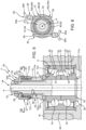
- the control unit 50 comprises ( Figures 3 and 4 ):
- the shaft 6 is hollow.
- the shaft 6 further comprises ( Figure 3 ):
- the main portion 22 further defines a flange 19 adapted to receive the motion from the shaft 13 ( Figure 3 ) .
- the shaft 6 has a maximum diameter at the flange 19, and progressively decreasing diameters proceeding from the flange 19 towards the ends 20, 21.
- the rod 10 is partially housed inside by shaft 6.
- the rod 10 further comprises:
- the ends 23, 24 are arranged externally to the shaft 6 and on the side of the ends 20, 21, respectively.
- the main body 25 is operatively connected to the flight control 15 by means of a lever mechanism (not shown) or by means of a wireless type drive.
- the element 16 comprises, in turn:
- the flange 42 and the bearing 17 are housed on the outside of the shaft 6 and surround the rod 10.
- the flange 42 and the bearing 17 are arranged on the opposite side of the end 20, 23 with respect to the ends 21, 24.
- the flange 42 is connected to the shaft 6 by a single variable-length bellows 44, which allows it to slide along the axis A.
- the lever mechanisms 43 are generally inclined with respect to the axis A and extend from the flange 42 towards the ends 20, 23.
- lever mechanisms 43 are articulated on the root portions 14 of the respective blades 8.
- the bearing 17 is capable of transmitting axial loads parallel to the axis A in both directions.
- the bearing 17 is configured so that the translation of the rod 10 along the axis A in both directions causes the translation of the element 16 in the same directions.
- the bearing 17 thus defines a transmission group, which connects the rod 10 and the element 16 in an axially integral and angularly movable manner with respect to the axis A.
- the bearing 17 comprises, in turn ( Figure 5 ):
- the ring 31 has a pair of axial end shoulders 35, 36 that are opposite each other, projecting radially towards the ring 30 and defining respective axial abutment surfaces for the rolling bodies 32.
- the rolling bodies 32 are, in particular, axially interposed between the shoulders 35, 36.
- the ring 31 is furthermore made up of two half-rings that are arranged in contact axially the one against the other, in the case shown.
- the ring 30 comprises a shoulder 37 interposed axially between the shoulders 35, 36, projecting radially towards the ring 31 and defining respective abutment surfaces for the rolling bodies 32.
- the shoulder 37 is axially interposed between the rolling elements 32 at a plane of symmetry of the bearing 17 radial to the axis A.
- the external ring 30, moreover, is fixed on the tubular body 40 of the element 16 in a position that is radially internal to the axis A with respect to the flange 42.
- the internal ring 31 is made integral with the control rod 10 by means of constraint conditions which act both axially and radially with respect to the axis A.
- constraint conditions which act both axially and radially with respect to the axis A.
- the movement of the internal ring 31 with respect to the control rod 10 parallel to the axis A is prevented both in the direction oriented from the end 23 to the end 24, and in the opposite direction.
- the movement of the ring 31 with respect to the control rod 10 in the radial direction is prevented by an interference coupling.
- the internal ring 31 comprises an axial end 31a, which is arranged on the side of the end 23, and an axial end 31b opposite the end 31a.
- control device 50 comprises an axial locking element 38, which cooperates with the axial end 31a and prevents the axial movement of the internal ring 31 in the direction oriented from the end 24 to the end 23.
- control rod 10 comprises a shoulder 39, which defines the axial locking element 38.
- the internal ring 31 axially abuts against the shoulder 39 at the axial end 31a ( Figure 5 ).
- the control rod 10 further comprises a threaded portion 10a and the control device 50 further comprises a threaded element 51, which is screwed onto the control rod 10 at the threaded portion 10a and cooperating with the axial end 31b ( Figures 4 and 5 ). In this way, the axial constraint of the internal ring 31 is realized on the side of the axial end 31b.
- the threaded element 51 is a cylindrical body mounted coaxially to the axis A and comprising a radially internal threaded portion 56 and a radially external portion 55 ( Figure 5 ).
- the radially internal portion 56 is screwed onto the threaded portion 10a.
- the threaded element 51 is a locking nut.
- the threaded portion 10a is obtained in proximity to the end 24 and, in particular, along an axial section of the control rod 10 extending from the side opposite the shoulder 39 with respect to the bearing 17.
- Control device 50 comprises a bushing 52 coupled in an angularly and axially fixed manner to the threaded element 51 and in an angularly fixed manner to the control rod 10.
- the bushing 52 is coupled in an angularly fixed manner to the control rod 10 independently of the threaded element 51. Therefore, even if the bushing 52 were not angularly fixed with respect to the threaded element 51, the bushing 52 could not rotate with respect to the control rod 10.
- the bushing 52 constitutes an anti-unscrewing device of the threaded element 51 with respect to the control rod 10.
- the bushing 52 exerts a contrasting action on the threaded element 51, which is the resultant of a plurality of forces and/or moments and which opposes the rotation of the threaded element 51 with respect to the control rod 10.
- the bushing 52 is a cylindrical body mounted coaxially to the axis A on the side opposite the end 23 with respect to the threaded element 51.
- the bushing 52 comprises a radially internal portion 58 and a radially external portion 57.
- the bushing 52 further comprises an axial end 52a which is arranged on the side of the end 23 and an axial end 52b which is axially opposite to the end 52a ( Figures 5 to 9 ).
- the bushing 52 comprises a cylindrical section 53 arranged on the side of the axial end 52a and a cylindrical section 54 arranged on the side of the axial end 52b.
- the cylindrical sections 53 and 54 are concentric to each other and superimposed the one above the other parallel to the axis A.
- the cylindrical sections 53 and 54 have respective external diameters that are different from each other.
- the external diameter of the cylindrical section 53 is greater than that of the cylindrical section 54.
- the axial extension of the cylindrical section 54 is smaller than that of the cylindrical section 53.
- the bushing 52 is angularly coupled to the threaded element 51 by means of a shape coupling 60.
- the threaded element 51 comprises a profile 61 at the radially external portion 55 and the bushing 52 comprises a profile 62 that is complementary in shape to that of the profile 61 at the radially internal portion 58 ( Figures 7, 8 and 10 ).
- the profile 61 is a radially external grooved profile 61 and the profile 62 is a radially internal grooved profile 62.
- the radially external grooved profile 61 and the radially internal grooved profile 62 are such that they can be reversibly coupled to each other.
- the external and internal grooved profiles 61, 62 can be made by means of a broaching process.
- the external and internal grooved profiles 61, 62 respectively comprise a plurality of teeth 64, 65, preferably straight parallel to the axis A.
- the number of teeth 64 and the number of teeth 65 are odd.
- the meshing between the teeth 64 and the teeth 65 prevents the threaded element 51 and the bushing 52 from rotating the one with respect to the other.
- the axial extension of the external and internal grooved profiles 61, 62 is related to the contrasting action that the bushing 52 exerts on the threaded element 51.
- the extent of the contrasting action increases as the axial extension of the external and internal grooved profiles 61, 62 increases.
- the threaded element 51 comprises a cylindrical section 51a arranged on the side of the end 23 and a cylindrical section 51b arranged on the side of the end 24.
- the cylindrical sections 51a and 51b are concentric to each other and superimposed the one above the other parallel to the axis A.
- the cylindrical sections 51a and 51b have respective external diameters that are different from each other.
- the external diameter of the cylindrical section 51a is greater than that of the cylindrical section 51b ( Figures 7, 8 and 10 ). Consequently, the threaded member 51 comprises a shoulder 51c at the longitudinal section of the threaded element 51 wherein the cylindrical section 51a joins the cylindrical section 51b.
- the bushing 52 axially abuts against this shoulder 51c on the side of the axial end 52a ( Figures 5 and 10 ).
- the external grooved profile 61 extends at the cylindrical section 51b, preferably along its entire axial extension.
- the cylindrical section 51a is preferably smooth at the radially external portion 55 and has a hexagonal or octagonal profile in a plane orthogonal to the axis A.
- the thread of the threaded element 51 moreover, extends along both the cylindrical sections 51a and 51b.
- the internal grooved profile 62 extends along the cylindrical section 53, preferably along its entire axial extension ( Figures 4 and 7 ).
- the threaded element 51 is of the non-self-braking type.
- the bushing 52 is angularly coupled to the control rod 10 by means of a shape coupling 70.
- control rod 10 comprises a polygonal profile 71, 71' and the bushing 52 comprises a polygonal profile 72, 72' and with a shape complementary to that of the profile 71, 71'.
- the profile 71, 71' and the profile 72, 72' define the shape coupling 70.
- the profile 71, 71' is arranged at an internal diameter of the control rod 10 and the profile 72, 72' is arranged at the radially internal portion 58.
- the profile 71, 71' extends near the end 24 and the profile 72, 72' extends near the axial end 52b.
- the profile 71, 71' extends along an axial section of the control rod 10 starting from the end 24 and the profile 72, 72' extends along the entire cylindrical section 54 parallel to the axis A.
- the profile 71 in a plane perpendicular to the axis A, the profile 71 comprises an annular portion 71a concentric to the axis A and a plurality of elements 71b with prevalently axial development, projecting radially from the annular portion 71a and angularly equidistant to each other around the axis A.
- the elements 71b are teeth connected to the annular portion 71a, contiguous to each other and are six in number.
- the profile 71 has the shape of a six-pointed star in a section perpendicular to the axis A.
- the profile 72 has a shape corresponding to that of the profile 71 and defines the perimeter of a through hole obtained at the axial end 52b and having an axis parallel to the axis A ( Figure 7 ).
- the profile 72 is formed by a plurality of seats engaged by respective elements 71b.
- the profile 71' has a square shape in a plane orthogonal to the axis A and the profile 72' is shaped to engage the profile 71'.
- control device 50 comprises axial fixing means 80, which make the threaded element 51 and the bushing 52 axially integral.
- the axial fixing means 80 constitute additional anti-unscrewing devices that are adapted to prevent the accidental unscrewing of the threaded element 51 from the threaded portion 10a.
- the axial fixing means 80 comprise ( Figure 10 ):
- the seats 81, 82 are arranged at the radially external portion 55.
- the seats 81, 82 are spaced apart parallel to the axis A and are preferably identical to each other ( Figures 7, 8 and 10 ) .
- the seats 81 and 82 extend along the entire circumference of the radially external portion 55 on respective planes perpendicular to the axis A. Furthermore, the seats 81 and 82 are obtained at the cylindrical section 51b and in particular at the external grooved profile 61. More particularly, the seats 81 and 82 radially define a recess with respect to the head of the teeth 64.
- the two groups of openings 83a, 83b, 84a, 84b are each obtained at respective distinct parts of the bushing 52.
- the two groups of openings 83a, 83b, 84a, 84b are diametrically opposite to each other.
- the group of openings comprises two inlet openings 83a, 84a for the insertion of the filiform deformable element 85 and two outlet openings 83b, 84b for the exit of the filiform deformable element 85.
- the inlet openings 83a, 84a are aligned with each other parallel to the axis A and the same applies to the outlet openings 83b, 84b.
- the inlet opening 83a is aligned with the outlet opening 83b and the inlet opening 84a is aligned with the outlet opening 84b circumferentially with respect to the axis A.
- the openings 83a, 83b, 84a, 84b, moreover, are obtained at the cylindrical section 53.
- the two groups of seats 86, 87 which each comprise two seats, are also obtained at the cylindrical section 53 ( Figure 8 ). Furthermore, the two seats 86, 87 of each group of seats are spaced apart parallel to the axis A and are preferably identical to each other. More in detail, the seats 86 and 87 of each pair of seats extend along a circular sector of the bushing 52.
- Each seat 86 extends between an inlet opening 83a and the respective outlet opening 83b and each seat 87 extends between an inlet opening 84a and the respective outlet opening 84b.
- the seats 86 and 87 are obtained at the internal groove profile 62.
- the seats 86 and 87 also radially define a recess with respect to the head of the teeth 65.
- the distance between a seat 86 and the relative seat 87 parallel to the axis A is equal to the axial distance between the seats 81 and 82 parallel to the axis A.
- the seats 81, 82, 86 and 87 are shaped so as to house the filiform deformable element 85.
- FIGS 7, 8 and 10 show the filiform deformable element 85 in an initial configuration, i.e. before it is engaged with the threaded element 51 and the bushing 52.
- the filiform deformable element 85 comprises two straight sections 88, 89 and parallel to each other and a curvilinear section 90, which joins the two straight sections 88, 89.
- the filiform deformable element 85 also comprises two free ends 85a, 85b opposite each other, which are defined respectively by the straight sections 88 and 89 on the side opposite to the curvilinear section 90.
- the filiform deformable element 85 is preferably made of metallic material and is, for example, a brake wire.
- the seats 81 and 82 are at least partially facing the seats 86 and 87 respectively and house respective portions of the filiform deformable element 85.
- the filiform deformable element 85 has a circular cross-section. Consequently, the seats 81, 82, 86 and 87 have an arc-shaped profile of a circumference in a plane passing through the axis A.
- the filiform deformable element 85 may have a cross section with shapes other than the circular one.
- Figure 9 shows the filiform deformable element 85 in a final configuration, i.e. once the filiform deformable element 85 is engaged with the threaded element 51 and with the bushing 52.
- the straight section 88 which is placed on the side of the end 23, passes through the inlet opening 83a, engages the seats 81 and 86 and comes out from the outlet opening 83b;
- the straight section 89 which is placed on the side of the end 24, passes through the inlet opening 84a, engages the seats 82, 87 and comes out from the outlet opening 84b.
- each straight section 88, 89 is partially housed in the seats 81, 82, 86, 87 and partially outside these seats.
- the curvilinear section 90 and the free ends 85a, 85b are outside the seats 81, 82, 86, 87.
- the free ends 85a, 85b are plastically deformed so that they are twisted together and then fixed the one to the other. Consequently, the free ends 85a, 85b place the filiform deformable element 85 under traction and prevent the straight sections 88, 89 from being able to vary their distance parallel to the axis A during use.
- the straight section 88 is interposed between two sections of the teeth 64 and two sections of the teeth 65 parallel to the axis A.
- the straight section 89 is interposed between two sections of the teeth 64 and two sections of the teeth 65 parallel to the axis A. Therefore, as a consequence of the tensile stress to which the filiform deformable element 85 is subjected, the straight sections 88 and 89 exert respective actions parallel to the axis A and oriented towards the end 24 and towards the end 23, respectively.
- the control device 50 also comprises a washer 100, which is fitted around the control rod 10 and axially interposed between the bearing 17 and the threaded element 51.
- the washer 100 axially abuts against the internal ring 31 at the end 31b and against the threaded element 51 on the side of the cylindrical section 51a.
- the bearing 17 is fitted from the end 24 coaxially to the axis A and slid axially until the internal ring 31 abuts against the shoulder 39 at the axial end 31a.
- the washer 100 is inserted, which is placed so as to abut against the axial end 31b.
- the threaded element 51 is therefore also fitted around the control rod 10 from the end 24 and from the side of the cylindrical section 51a.
- the threaded element 51 is then rotated about the axis A, so that the radially internal portion 56 is screwed onto the threaded portion 10a.
- the threaded element 51 is progressively screwed - for example by means of a torque wrench - around the control rod 10 until it is tightened to the predetermined torque.
- the threaded element 51 abuts against the washer 100 on the side of the cylindrical section 51a.
- the bushing 52 is then inserted from the end 24 so as to be axially stacked with the threaded element 51.
- the shape coupling 60 and the shape coupling 70 are both geometrically respected. Therefore, it is necessary that profile 61 is correctly coupled to the profile 62 and that at the same time the profile 71, 71' is correctly coupled to the profile 72, 72'.
- the teeth 64 of the external grooved profile 61 must be angularly placed so as to be able to mesh correctly with the teeth 65 of the internal grooved profile 62 and at the same time, the elements 71b must be able to engage the corresponding seats of the profile 72 or that the square-shaped profile 71' can geometrically engage the profile 72'.
- the bushing 52 is angularly fixed with respect to the threaded element 51 and with respect to the control rod 10.
- each filiform deformable element 85 is inserted partly into the seats 81, 86 and partly into the seats 82, 87, and deformed at its free ends 85a, 85b which come out from the seats 81, 82, 86, 87, in order to prevent the relative axial displacement between the threaded element 51 and the bushing 52 ( Figure 6 ).
- the straight section 88 is inserted from the free end 85a through the inlet opening 83a into the seats 81 and 86 until it partially comes out from the outlet opening 83b; at the same time, the straight section 89 is inserted from the free end 85b through the inlet opening 84a into the seats 82, 87 until it partially comes out from the outlet opening 84b.
- the free ends 85a and 85b are then twisted together so that they are fixed the one to the other.
- the actuation of the rotor 4 results in the rotation of the shaft 6 and of the hub 9 around the axis A and, consequently, the generation of the contrasting torque on the fuselage 2.
- the rotation of the rotor 4 causes vibrations to be triggered, which are transmitted to the threaded element 51 through the control rod 10 and which tend to unscrew the threaded element 51 itself from the threaded portion 10a.
- the bushing 52 is angularly integral with the threaded element 51 by means of the shape coupling 60 and the control rod 10 by means of the shape coupling 70. Therefore, the rotation of the threaded element 51 about the axis A is prevented by the fact that the bushing 52 cannot rotate with respect to the control rod 10.
- the filiform deformable elements 85 which are housed in the seats 81, 82 and in the seats 86, 87, exert on the threaded element 51 and on the bushing 52 actions directed parallel to the axis A, which oppose the distancing between the bushing 52 and the threaded element 51.
- the bushing 52 is angularly and axially fixed to the threaded element 51 and is angularly fixed to the control rod 10.
- the axial displacement of the radial internal ring 31 with respect to the control rod 10 can be reliably and efficiently limited.
- a threaded element 51 which is not of the self-braking type also allows to impart and maintain a tightening torque with a defined and non-variable value within a range of values.
- the threaded element 51 can be used for a much greater number of tightening cycles than that allowed by the self-braking nuts.
- a similar concept can be applied when considering the profile 71, 71' of the control rod and the profile 72, 72' of the bushing 52. Since the control rod 10 comprises the profile 71, 71' and the bushing 52 comprises the profile 72, 72' and since both said profiles 71, 71', 72, 72' are polygonal, the bushing 52 can be coupled to the control rod 10 for a discrete number of angular positions with respect to the axis A.
- the axial locking element 38 could comprise an elastic stop ring, for example a Seeger ring.
- the profiles 71, 71'; 72, 72' may be shaped differently, i.e. have complementary shapes other than those shown in Figures 7 and 10 .
- the profile 71 could comprise a number of elements 71b other than six.
- the filiform deformable element 85 may be different from a brake wire.
- the filiform deformable element 85 may be a split pin.
Landscapes
- Engineering & Computer Science (AREA)
- Mechanical Engineering (AREA)
- Aviation & Aerospace Engineering (AREA)
- General Engineering & Computer Science (AREA)
- Mutual Connection Of Rods And Tubes (AREA)
- Chairs For Special Purposes, Such As Reclining Chairs (AREA)
- Transmission Devices (AREA)
Claims (13)
- Dispositif de commande (50) pour commander la variation de l'angle d'attaque des pales (8) d'un rotor anti-couple (4) pour un aéronef (1) capable d'effectuer un vol stationnaire, comprenant :un élément de commande (16) coulissant le long d'un premier axe (A) par rapport à un arbre (6) dudit rotor anti-couple (4) et pouvant tourner de manière solidaire avec ledit arbre (6) ; ledit élément de commande (16) étant, de plus, raccordé de manière opérationnelle à une pluralité desdites pales (8) articulées sur ledit arbre (6) afin de provoquer, à l'usage, leur rotation autour des seconds axes (B) respectifs suite à une translation dudit élément (16) lui-même le long dudit premier axe (A) ;une tige de commande (10) coulissant, de manière axiale, le long dudit premier axe (A) par rapport audit arbre (6) et fixe, de manière angulaire, par rapport audit premier axe (A) ; etun palier à roulement (17) intercalé entre ladite tige de commande (10) et ledit élément de commande (16), coulissant le long dudit premier axe (A) par rapport audit arbre (6) et de manière solidaire avec ladite tige de commande (10), et configuré pour permettre la rotation relative dudit élément de commande (16) par rapport à ladite tige de commande (10) autour duit premier axe (A) ;ledit palier à roulement (17) comprenant à son tour :une première bague (30) qui peut tourner, de manière solidaire, avec ledit élément de commande (16) autour dudit premier axe (A) ;une seconde bague (31) radialement interne à ladite première bague (30) par rapport audit premier axe (A) et coulissant, de manière solidaire, avec ladite tige de commande (10) le long dudit premier axe (A) ; etune pluralité de corps de roulement (32), qui sont intercalés entre lesdites première et seconde bagues (30, 31) et adaptés pour rouler sur des pistes (33, 34) respectives desdites première et seconde bagues (30, 31) ;ledit dispositif de commande (50) comprenant en outre un élément fileté (51) vissé sur ladite tige de commande (10) et coopérant avec ladite seconde bague (31) pour la contraindre axialement par rapport à ladite tige de commande (10) ;ledit dispositif de commande (50) comprenant en outre :une douille (52) couplée d'une manière angulairement et axialement fixe audit élément fileté (51), et d'une manière angulairement fixe à ladite tige de commande (10) ;des moyens de fixation axiaux (80) adaptés pour fixer ledit élément fileté (51) et ladite douille (52) entre eux, afin d'empêcher leurs mouvements relatifs parallèles audit premier axe (A) ;ledit élément fileté (51) comprenant une première partie radialement externe (55) et une première partie radialement interne (56) par rapport audit premier axe (A) et ladite douille (52) comprenant une seconde partie radialement externe (57) et une seconde partie radialement interne (58) ;caractérisé en ce que lesdits moyens de fixation axiaux (80) comprennent :au moins un premier siège (81, 82) qui est formé au niveau dudit élément fileté (51) ;une pluralité d'ouvertures (83a, 83b, 84a, 84b) formées au niveau de ladite douille (52) ;au moins un second siège (86, 87) obtenu au niveau de ladite douille (52) et faisant au moins partiellement face audit au moins un premier siège (81, 82) ; etun élément déformable filiforme (85), qui met en prise lesdits premier et second sièges (81, 82 ; 86, 87) et lesdites ouvertures (83a, 83b, 84a, 84b) ;dans lequel ledit au moins un premier siège (81, 82) s'étend le long de toute la circonférence de ladite première partie radialement externe (55) sur un plan perpendiculaire audit premier axe (A).
- Dispositif de commande selon la revendication 1, caractérisé en ce qu'il comprend :des premiers moyens de raccordement (60) adaptés pour raccorder ladite douille (52) audit élément fileté (51) ; etdes seconds moyens de raccordement (70) distincts desdits premiers moyens de raccordement (60) et adaptés pour raccorder ladite douille (52) à ladite tige de commande (10).
- Dispositif de commande selon la revendication 2, caractérisé en ce que lesdits premiers moyens de raccordement (60) comprennent un couplage de forme (60).
- Dispositif de commande selon la revendication 3, caractérisé en ce que ledit élément fileté (51) comprend un profil rainuré externe (61) au niveau de ladite première partie radialement externe (55) et ladite douille (52) comprend un profil rainuré interne (62) au niveau de ladite seconde partie radialement interne (58) ; ledit profil rainuré externe (61) et ledit profil rainuré interne (62) étant couplés ensemble et définissant ledit couplage de forme (60).
- Dispositif de commande selon la revendication 4, caractérisé en ce que ledit profil rainuré externe (61) et ledit profil rainuré interne (62) comprennent chacun un nombre impair de dents (64, 65).
- Dispositif de commande selon la revendication 4 ou 5, caractérisé en ce que ledit profil rainuré externe (61) et ledit profil rainuré interne (62) ont des extensions axiales respectives parallèles audit premier axe (A) ;ladite douille (52) exerçant, à l'usage, une action de contraste sur ledit élément fileté (51) ;ladite action de contraste étant une résultante de forces et/ou de moments ayant une direction opposée à la rotation de l'élément fileté (51) autour dudit premier axe (A) et ayant un module proportionnel auxdites extensions axiales.
- Dispositif de commande selon l'une quelconque des revendications 2 à 6, caractérisé en ce que lesdits seconds moyens de raccordement (70) comprennent un couplage de forme supplémentaire (70).
- Dispositif de commande selon la revendication 7, caractérisé en ce que ladite tige de commande (10) comprend un premier profil polygonal (71, 71') et ladite douille (52) comprend un second profil polygonal (72, 72') avec une forme correspondant audit premier profil polygonal (71, 71') ;
ledit premier profil polygonal (71, 71') et ledit second profil polygonal (72, 72') étant couplés ensemble et définit ledit couplage de forme supplémentaire (70). - Dispositif de commande selon l'une quelconque des revendications précédentes, caractérisé en ce que ledit élément déformable filiforme (85) est réalisé avec un matériau métallique.
- Dispositif de commande selon l'une quelconque des revendications précédentes, caractérisé en ce que ledit élément fileté (51) n'est pas du type auto-freinant.
- Dispositif de commande selon l'une quelconque les revendications précédentes, caractérisé en ce qu'il comprend une rondelle (100), qui est montée autour de ladite tige de commande (10) et est intercalée entre ledit palier à roulement (17) et ledit élément fileté (51) parallèlement audit premier axe (A).
- Rotor anti-couple (4) pour un aéronef (1) capable d'effectuer un vol stationnaire, comprenant :un arbre (6) pouvant tourner autour d'un premier axe (A) ;une pluralité de pales (8) articulées sur ledit arbre (6), s'étendant le long des seconds axes (B) respectifs transversaux par rapport audit premier axe (A) et pouvant tourner autour desdits seconds axes (B) respectifs afin de modifier des angles d'attaque respectifs ; etun dispositif de commande (50) selon l'une quelconque des revendications précédentes.
- Aéronef (1) capable d'effectuer un vol stationnaire, en particulier un hélicoptère (1), comprenant :un fuselage (2) ;un rotor principal (3) ; etun rotor anti-couple (4) selon la revendication 12.
Priority Applications (5)
| Application Number | Priority Date | Filing Date | Title |
|---|---|---|---|
| EP21205724.4A EP4173949B1 (fr) | 2021-10-29 | 2021-10-29 | Dispositif de commande pour varier l'angle d'attaque des pales d'un rotor anticouple pour un aéronef capable d'effectuer un vol stationnaire |
| EP22735037.8A EP4422972B1 (fr) | 2021-10-29 | 2022-06-23 | Dispositif de commande pour varier l'angle d'attaque des pales d'un rotor anticouple pour un aéronef capable d'effectuer un vol stationnaire |
| KR1020247017983A KR20240091193A (ko) | 2021-10-29 | 2022-06-23 | 호버링을 할 수 있는 항공기를 위한 반토크 로터의 블레이드들의 받음각을 변경하기 위한 제어 장치 |
| PCT/IB2022/055834 WO2023073440A1 (fr) | 2021-10-29 | 2022-06-23 | Dispositif de commande pour faire varier l'angle d'attaque des pales d'un rotor anticouple pour un aéronef pouvant faire un vol stationnaire |
| CN202280072707.6A CN118176151A (zh) | 2021-10-29 | 2022-06-23 | 用于改变能够悬停的飞行器的抗扭矩旋翼的桨叶的迎角的控制装置 |
Applications Claiming Priority (1)
| Application Number | Priority Date | Filing Date | Title |
|---|---|---|---|
| EP21205724.4A EP4173949B1 (fr) | 2021-10-29 | 2021-10-29 | Dispositif de commande pour varier l'angle d'attaque des pales d'un rotor anticouple pour un aéronef capable d'effectuer un vol stationnaire |
Publications (2)
| Publication Number | Publication Date |
|---|---|
| EP4173949A1 EP4173949A1 (fr) | 2023-05-03 |
| EP4173949B1 true EP4173949B1 (fr) | 2024-12-04 |
Family
ID=79170761
Family Applications (2)
| Application Number | Title | Priority Date | Filing Date |
|---|---|---|---|
| EP21205724.4A Active EP4173949B1 (fr) | 2021-10-29 | 2021-10-29 | Dispositif de commande pour varier l'angle d'attaque des pales d'un rotor anticouple pour un aéronef capable d'effectuer un vol stationnaire |
| EP22735037.8A Active EP4422972B1 (fr) | 2021-10-29 | 2022-06-23 | Dispositif de commande pour varier l'angle d'attaque des pales d'un rotor anticouple pour un aéronef capable d'effectuer un vol stationnaire |
Family Applications After (1)
| Application Number | Title | Priority Date | Filing Date |
|---|---|---|---|
| EP22735037.8A Active EP4422972B1 (fr) | 2021-10-29 | 2022-06-23 | Dispositif de commande pour varier l'angle d'attaque des pales d'un rotor anticouple pour un aéronef capable d'effectuer un vol stationnaire |
Country Status (4)
| Country | Link |
|---|---|
| EP (2) | EP4173949B1 (fr) |
| KR (1) | KR20240091193A (fr) |
| CN (1) | CN118176151A (fr) |
| WO (1) | WO2023073440A1 (fr) |
Family Cites Families (5)
| Publication number | Priority date | Publication date | Assignee | Title |
|---|---|---|---|---|
| US121176A (en) * | 1871-11-21 | Improvement in lock-nuts | ||
| GB2539218A (en) * | 2015-06-09 | 2016-12-14 | Airbus Operations Ltd | A pin assembly |
| WO2017020286A1 (fr) | 2015-08-06 | 2017-02-09 | 杨东佐 | Écrou de fixation, structure d'arrêt en rotation, composant et structure de connecteur de fixation, procédé de montage et de démontage, structure de piste, mécanisme de vilebrequin et bielle, appareil de liaison de cadre, procédé de liaison de cadre, appareil à arbre de liaison, ossature de roue, arrêtoir à bille de vélo et cadre a roues |
| FR3067769B1 (fr) * | 2017-06-15 | 2019-07-19 | Lisi Aerospace | Fixation a verrouillage positif |
| EP3753849B1 (fr) * | 2019-06-17 | 2021-08-04 | LEONARDO S.p.A. | Rotor anticouple pour hélicoptère |
-
2021
- 2021-10-29 EP EP21205724.4A patent/EP4173949B1/fr active Active
-
2022
- 2022-06-23 CN CN202280072707.6A patent/CN118176151A/zh active Pending
- 2022-06-23 KR KR1020247017983A patent/KR20240091193A/ko active Pending
- 2022-06-23 EP EP22735037.8A patent/EP4422972B1/fr active Active
- 2022-06-23 WO PCT/IB2022/055834 patent/WO2023073440A1/fr not_active Ceased
Also Published As
| Publication number | Publication date |
|---|---|
| KR20240091193A (ko) | 2024-06-21 |
| CN118176151A (zh) | 2024-06-11 |
| EP4422972A1 (fr) | 2024-09-04 |
| EP4422972B1 (fr) | 2025-03-26 |
| WO2023073440A1 (fr) | 2023-05-04 |
| EP4173949A1 (fr) | 2023-05-03 |
Similar Documents
| Publication | Publication Date | Title |
|---|---|---|
| JP2768826B2 (ja) | 回転翼型航空機の尾部回転翼のダクトファンおよびピッチ制御装置 | |
| US10934866B2 (en) | Variable pitch change control method | |
| EP3753850B1 (fr) | Rotor anticouple pour hélicoptère | |
| US5160005A (en) | Pawl and ratchet clutch with torsion shaft | |
| EP4173949B1 (fr) | Dispositif de commande pour varier l'angle d'attaque des pales d'un rotor anticouple pour un aéronef capable d'effectuer un vol stationnaire | |
| EP2995830B1 (fr) | Accouplement flexible | |
| US6692399B2 (en) | Differential torque limiter | |
| US20240093761A1 (en) | Drive and/or adjustment device having overload protection | |
| CN116097005A (zh) | 包括可变桨距螺旋桨轮叶的飞行器涡轮发动机 | |
| WO2016201079A1 (fr) | Sangle de torsion de tension | |
| EP3753849B1 (fr) | Rotor anticouple pour hélicoptère | |
| WO2013001324A1 (fr) | Dispositif de protection contre la rotation d'arbre | |
| EP4133190B1 (fr) | Bout de tige et dispositif de verrouillage pour bielle | |
| EP3137377B1 (fr) | Arbre de torsion creux radialement élastique | |
| US12116106B2 (en) | Rotor blade with a system for retention and for take-up of separate stresses and rotor provided with such blades | |
| EP3572322B1 (fr) | Ensemble de tige d'actionneur pour un système de commande de pas de pale | |
| US11649039B1 (en) | Aerostructure actuation system | |
| US8240601B2 (en) | Coupling with slack-takeup, a rotor, and a rotary wing aircraft | |
| EP3404256B1 (fr) | Dispositif d'ajustement des pales de rotor d'une installation génératrice d'énergie à flux | |
| US20070104580A1 (en) | Rotorcraft rotors having twistable blades | |
| EP4015856B1 (fr) | Joint d'actionneur de rotor de queue | |
| CN223014890U (zh) | 旋翼头和直升机 | |
| CN219339706U (zh) | 一种飞机飞行控制操纵钢索系统的钢索张力调节机构 | |
| US20250002136A1 (en) | Bearing Anti-Creep Interface | |
| CN113167223B (zh) | 风力涡轮机叶片桨距系统 |
Legal Events
| Date | Code | Title | Description |
|---|---|---|---|
| PUAI | Public reference made under article 153(3) epc to a published international application that has entered the european phase |
Free format text: ORIGINAL CODE: 0009012 |
|
| STAA | Information on the status of an ep patent application or granted ep patent |
Free format text: STATUS: REQUEST FOR EXAMINATION WAS MADE |
|
| STAA | Information on the status of an ep patent application or granted ep patent |
Free format text: STATUS: EXAMINATION IS IN PROGRESS |
|
| 17P | Request for examination filed |
Effective date: 20220503 |
|
| AK | Designated contracting states |
Kind code of ref document: A1 Designated state(s): AL AT BE BG CH CY CZ DE DK EE ES FI FR GB GR HR HU IE IS IT LI LT LU LV MC MK MT NL NO PL PT RO RS SE SI SK SM TR |
|
| 17Q | First examination report despatched |
Effective date: 20230503 |
|
| P01 | Opt-out of the competence of the unified patent court (upc) registered |
Effective date: 20231005 |
|
| GRAP | Despatch of communication of intention to grant a patent |
Free format text: ORIGINAL CODE: EPIDOSNIGR1 |
|
| STAA | Information on the status of an ep patent application or granted ep patent |
Free format text: STATUS: GRANT OF PATENT IS INTENDED |
|
| INTG | Intention to grant announced |
Effective date: 20240618 |
|
| GRAS | Grant fee paid |
Free format text: ORIGINAL CODE: EPIDOSNIGR3 |
|
| GRAA | (expected) grant |
Free format text: ORIGINAL CODE: 0009210 |
|
| STAA | Information on the status of an ep patent application or granted ep patent |
Free format text: STATUS: THE PATENT HAS BEEN GRANTED |
|
| AK | Designated contracting states |
Kind code of ref document: B1 Designated state(s): AL AT BE BG CH CY CZ DE DK EE ES FI FR GB GR HR HU IE IS IT LI LT LU LV MC MK MT NL NO PL PT RO RS SE SI SK SM TR |
|
| REG | Reference to a national code |
Ref country code: CH Ref legal event code: EP |
|
| REG | Reference to a national code |
Ref country code: DE Ref legal event code: R096 Ref document number: 602021022778 Country of ref document: DE |
|
| REG | Reference to a national code |
Ref country code: IE Ref legal event code: FG4D |
|
| REG | Reference to a national code |
Ref country code: LT Ref legal event code: MG9D |
|
| REG | Reference to a national code |
Ref country code: NL Ref legal event code: MP Effective date: 20241204 |
|
| PG25 | Lapsed in a contracting state [announced via postgrant information from national office to epo] |
Ref country code: HR Free format text: LAPSE BECAUSE OF FAILURE TO SUBMIT A TRANSLATION OF THE DESCRIPTION OR TO PAY THE FEE WITHIN THE PRESCRIBED TIME-LIMIT Effective date: 20241204 |
|
| PG25 | Lapsed in a contracting state [announced via postgrant information from national office to epo] |
Ref country code: FI Free format text: LAPSE BECAUSE OF FAILURE TO SUBMIT A TRANSLATION OF THE DESCRIPTION OR TO PAY THE FEE WITHIN THE PRESCRIBED TIME-LIMIT Effective date: 20241204 |
|
| PG25 | Lapsed in a contracting state [announced via postgrant information from national office to epo] |
Ref country code: BG Free format text: LAPSE BECAUSE OF FAILURE TO SUBMIT A TRANSLATION OF THE DESCRIPTION OR TO PAY THE FEE WITHIN THE PRESCRIBED TIME-LIMIT Effective date: 20241204 |
|
| PG25 | Lapsed in a contracting state [announced via postgrant information from national office to epo] |
Ref country code: ES Free format text: LAPSE BECAUSE OF FAILURE TO SUBMIT A TRANSLATION OF THE DESCRIPTION OR TO PAY THE FEE WITHIN THE PRESCRIBED TIME-LIMIT Effective date: 20241204 |
|
| PG25 | Lapsed in a contracting state [announced via postgrant information from national office to epo] |
Ref country code: NO Free format text: LAPSE BECAUSE OF FAILURE TO SUBMIT A TRANSLATION OF THE DESCRIPTION OR TO PAY THE FEE WITHIN THE PRESCRIBED TIME-LIMIT Effective date: 20250304 |
|
| PG25 | Lapsed in a contracting state [announced via postgrant information from national office to epo] |
Ref country code: LV Free format text: LAPSE BECAUSE OF FAILURE TO SUBMIT A TRANSLATION OF THE DESCRIPTION OR TO PAY THE FEE WITHIN THE PRESCRIBED TIME-LIMIT Effective date: 20241204 Ref country code: GR Free format text: LAPSE BECAUSE OF FAILURE TO SUBMIT A TRANSLATION OF THE DESCRIPTION OR TO PAY THE FEE WITHIN THE PRESCRIBED TIME-LIMIT Effective date: 20250305 |
|
| PG25 | Lapsed in a contracting state [announced via postgrant information from national office to epo] |
Ref country code: RS Free format text: LAPSE BECAUSE OF FAILURE TO SUBMIT A TRANSLATION OF THE DESCRIPTION OR TO PAY THE FEE WITHIN THE PRESCRIBED TIME-LIMIT Effective date: 20250304 |
|
| PG25 | Lapsed in a contracting state [announced via postgrant information from national office to epo] |
Ref country code: NL Free format text: LAPSE BECAUSE OF FAILURE TO SUBMIT A TRANSLATION OF THE DESCRIPTION OR TO PAY THE FEE WITHIN THE PRESCRIBED TIME-LIMIT Effective date: 20241204 |
|
| REG | Reference to a national code |
Ref country code: AT Ref legal event code: MK05 Ref document number: 1747934 Country of ref document: AT Kind code of ref document: T Effective date: 20241204 |
|
| PG25 | Lapsed in a contracting state [announced via postgrant information from national office to epo] |
Ref country code: SM Free format text: LAPSE BECAUSE OF FAILURE TO SUBMIT A TRANSLATION OF THE DESCRIPTION OR TO PAY THE FEE WITHIN THE PRESCRIBED TIME-LIMIT Effective date: 20241204 |
|
| PG25 | Lapsed in a contracting state [announced via postgrant information from national office to epo] |
Ref country code: PL Free format text: LAPSE BECAUSE OF FAILURE TO SUBMIT A TRANSLATION OF THE DESCRIPTION OR TO PAY THE FEE WITHIN THE PRESCRIBED TIME-LIMIT Effective date: 20241204 |
|
| PG25 | Lapsed in a contracting state [announced via postgrant information from national office to epo] |
Ref country code: IS Free format text: LAPSE BECAUSE OF FAILURE TO SUBMIT A TRANSLATION OF THE DESCRIPTION OR TO PAY THE FEE WITHIN THE PRESCRIBED TIME-LIMIT Effective date: 20250404 |
|
| PG25 | Lapsed in a contracting state [announced via postgrant information from national office to epo] |
Ref country code: PT Free format text: LAPSE BECAUSE OF FAILURE TO SUBMIT A TRANSLATION OF THE DESCRIPTION OR TO PAY THE FEE WITHIN THE PRESCRIBED TIME-LIMIT Effective date: 20250404 |
|
| PG25 | Lapsed in a contracting state [announced via postgrant information from national office to epo] |
Ref country code: EE Free format text: LAPSE BECAUSE OF FAILURE TO SUBMIT A TRANSLATION OF THE DESCRIPTION OR TO PAY THE FEE WITHIN THE PRESCRIBED TIME-LIMIT Effective date: 20241204 |
|
| PG25 | Lapsed in a contracting state [announced via postgrant information from national office to epo] |
Ref country code: RO Free format text: LAPSE BECAUSE OF FAILURE TO SUBMIT A TRANSLATION OF THE DESCRIPTION OR TO PAY THE FEE WITHIN THE PRESCRIBED TIME-LIMIT Effective date: 20241204 Ref country code: AT Free format text: LAPSE BECAUSE OF FAILURE TO SUBMIT A TRANSLATION OF THE DESCRIPTION OR TO PAY THE FEE WITHIN THE PRESCRIBED TIME-LIMIT Effective date: 20241204 |
|
| PG25 | Lapsed in a contracting state [announced via postgrant information from national office to epo] |
Ref country code: SK Free format text: LAPSE BECAUSE OF FAILURE TO SUBMIT A TRANSLATION OF THE DESCRIPTION OR TO PAY THE FEE WITHIN THE PRESCRIBED TIME-LIMIT Effective date: 20241204 |
|
| PG25 | Lapsed in a contracting state [announced via postgrant information from national office to epo] |
Ref country code: CZ Free format text: LAPSE BECAUSE OF FAILURE TO SUBMIT A TRANSLATION OF THE DESCRIPTION OR TO PAY THE FEE WITHIN THE PRESCRIBED TIME-LIMIT Effective date: 20241204 |
|
| REG | Reference to a national code |
Ref country code: DE Ref legal event code: R097 Ref document number: 602021022778 Country of ref document: DE |
|
| PG25 | Lapsed in a contracting state [announced via postgrant information from national office to epo] |
Ref country code: SE Free format text: LAPSE BECAUSE OF FAILURE TO SUBMIT A TRANSLATION OF THE DESCRIPTION OR TO PAY THE FEE WITHIN THE PRESCRIBED TIME-LIMIT Effective date: 20241204 |
|
| PG25 | Lapsed in a contracting state [announced via postgrant information from national office to epo] |
Ref country code: DK Free format text: LAPSE BECAUSE OF FAILURE TO SUBMIT A TRANSLATION OF THE DESCRIPTION OR TO PAY THE FEE WITHIN THE PRESCRIBED TIME-LIMIT Effective date: 20241204 |
|
| PLBE | No opposition filed within time limit |
Free format text: ORIGINAL CODE: 0009261 |
|
| STAA | Information on the status of an ep patent application or granted ep patent |
Free format text: STATUS: NO OPPOSITION FILED WITHIN TIME LIMIT |
|
| REG | Reference to a national code |
Ref country code: CH Ref legal event code: L10 Free format text: ST27 STATUS EVENT CODE: U-0-0-L10-L00 (AS PROVIDED BY THE NATIONAL OFFICE) Effective date: 20251015 |
|
| REG | Reference to a national code |
Ref country code: CH Ref legal event code: U11 Free format text: ST27 STATUS EVENT CODE: U-0-0-U10-U11 (AS PROVIDED BY THE NATIONAL OFFICE) Effective date: 20251101 |
|
| 26N | No opposition filed |
Effective date: 20250905 |
|
| PGFP | Annual fee paid to national office [announced via postgrant information from national office to epo] |
Ref country code: DE Payment date: 20251028 Year of fee payment: 5 |
|
| PGFP | Annual fee paid to national office [announced via postgrant information from national office to epo] |
Ref country code: GB Payment date: 20251023 Year of fee payment: 5 |
|
| PGFP | Annual fee paid to national office [announced via postgrant information from national office to epo] |
Ref country code: IT Payment date: 20251003 Year of fee payment: 5 |
|
| PGFP | Annual fee paid to national office [announced via postgrant information from national office to epo] |
Ref country code: FR Payment date: 20251027 Year of fee payment: 5 |
|
| PGFP | Annual fee paid to national office [announced via postgrant information from national office to epo] |
Ref country code: CH Payment date: 20251101 Year of fee payment: 5 |