EP4174238B1 - Montagerahmen - Google Patents
Montagerahmen Download PDFInfo
- Publication number
- EP4174238B1 EP4174238B1 EP22020112.3A EP22020112A EP4174238B1 EP 4174238 B1 EP4174238 B1 EP 4174238B1 EP 22020112 A EP22020112 A EP 22020112A EP 4174238 B1 EP4174238 B1 EP 4174238B1
- Authority
- EP
- European Patent Office
- Prior art keywords
- frame body
- support foot
- bracket
- mounting bracket
- water tank
- Prior art date
- Legal status (The legal status is an assumption and is not a legal conclusion. Google has not performed a legal analysis and makes no representation as to the accuracy of the status listed.)
- Active
Links
Images



Classifications
-
- E—FIXED CONSTRUCTIONS
- E03—WATER SUPPLY; SEWERAGE
- E03D—WATER-CLOSETS OR URINALS WITH FLUSHING DEVICES; FLUSHING VALVES THEREFOR
- E03D11/00—Other component parts of water-closets, e.g. noise-reducing means in the flushing system, flushing pipes mounted in the bowl, seals for the bowl outlet, devices preventing overflow of the bowl contents; devices forming a water seal in the bowl after flushing, devices eliminating obstructions in the bowl outlet or preventing backflow of water and excrements from the waterpipe
- E03D11/13—Parts or details of bowls; Special adaptations of pipe joints or couplings for use with bowls, e.g. provisions in bowl construction preventing backflow of waste-water from the bowl in the flushing pipe or cistern, provisions for a secondary flushing, for noise-reducing
- E03D11/14—Means for connecting the bowl to the wall, e.g. to a wall outlet
- E03D11/143—Mounting frames for toilets and urinals
- E03D11/146—Mounting frames for toilets and urinals with incorporated cistern
-
- F—MECHANICAL ENGINEERING; LIGHTING; HEATING; WEAPONS; BLASTING
- F16—ENGINEERING ELEMENTS AND UNITS; GENERAL MEASURES FOR PRODUCING AND MAINTAINING EFFECTIVE FUNCTIONING OF MACHINES OR INSTALLATIONS; THERMAL INSULATION IN GENERAL
- F16M—FRAMES, CASINGS OR BEDS OF ENGINES, MACHINES OR APPARATUS, NOT SPECIFIC TO ENGINES, MACHINES OR APPARATUS PROVIDED FOR ELSEWHERE; STANDS; SUPPORTS
- F16M13/00—Other supports for positioning apparatus or articles; Means for steadying hand-held apparatus or articles
- F16M13/02—Other supports for positioning apparatus or articles; Means for steadying hand-held apparatus or articles for supporting on, or attaching to, an object, e.g. tree, gate, window-frame, cycle
-
- E—FIXED CONSTRUCTIONS
- E03—WATER SUPPLY; SEWERAGE
- E03D—WATER-CLOSETS OR URINALS WITH FLUSHING DEVICES; FLUSHING VALVES THEREFOR
- E03D11/00—Other component parts of water-closets, e.g. noise-reducing means in the flushing system, flushing pipes mounted in the bowl, seals for the bowl outlet, devices preventing overflow of the bowl contents; devices forming a water seal in the bowl after flushing, devices eliminating obstructions in the bowl outlet or preventing backflow of water and excrements from the waterpipe
- E03D11/13—Parts or details of bowls; Special adaptations of pipe joints or couplings for use with bowls, e.g. provisions in bowl construction preventing backflow of waste-water from the bowl in the flushing pipe or cistern, provisions for a secondary flushing, for noise-reducing
- E03D11/135—Supports for bowls
-
- F—MECHANICAL ENGINEERING; LIGHTING; HEATING; WEAPONS; BLASTING
- F16—ENGINEERING ELEMENTS AND UNITS; GENERAL MEASURES FOR PRODUCING AND MAINTAINING EFFECTIVE FUNCTIONING OF MACHINES OR INSTALLATIONS; THERMAL INSULATION IN GENERAL
- F16M—FRAMES, CASINGS OR BEDS OF ENGINES, MACHINES OR APPARATUS, NOT SPECIFIC TO ENGINES, MACHINES OR APPARATUS PROVIDED FOR ELSEWHERE; STANDS; SUPPORTS
- F16M2200/00—Details of stands or supports
- F16M2200/02—Locking means
- F16M2200/025—Locking means for translational movement
Definitions
- the disclosure relates to the technical field of bathroom installation, in particular to a mounting bracket.
- the water tank components, toilet parts and other components assembled on the same mounting bracket are suspended from the ground to facilitate the user's cleaning of the ground.
- the height of these components suspended from the ground is constant. Therefore, it is difficult to meet the user's requirements for the suspension height during actual installation.
- SCHMUCKI PETER discloses a framework.
- the framework has at least one vertical support column, into which a telescopically height-adjustable foot connected to the support column is inserted.
- An approximate presetting and subsequently a fine height adjustment are possible by means of a height-adjustable adjusting member, which is self-supporting at the foot.
- LINDNER MICHAEL discloses a foot.
- the foot has a base plate running transverse to an extension of a hollow section leg and projecting laterally over the hollow section leg.
- the base plate is formed as integral extension of a rear side wall of the hollow section leg, and the base plate is bent relative to a side wall of the hollow section leg around 90 degrees.
- the base plate extends over a cross-section area of the hollow section leg where the hollow section leg is formed as a slotted square profile.
- the base plate is integrally connected with the side wall opposite to a slotted side wall.
- SEIFFERT JOACHIM discloses an installation support frame.
- the installation support frame is used with hollow wall units.
- the frame supports wall sanitary fittings, such as water closets or bidets.
- the frame has two vertical members connected by two horizontal spacers.
- the vertical member has slots for height adjustment of sanitary fittings.
- the system is readily installed.
- the support struts are made from rectangular hollow cross section profiles, pref. with square cross-section. Their rear side has longitudinal slots for fitting fastening screws for holding spacers. These in turn hold slotted holders espec. for adjustable and clamped attachment of the sanitary fittings along the spacers.
- FOMINAYA SA discloses a recessed frame for clamping of sanitary elements.
- the recessed frame for clamping of sanitary elements comprising a box of actuation mechanisms, an intermediate water tank and a lower structure for supporting and mounting the toilet, the three elements comprising a single one-piece part.
- the lower structure integrates a central crossbeam wherein two inclined crossbeams and one exhaust duct which leads into a central area of the central crossbeam flanked by the terminal sections of the inclined crossbeams converge. Jointly to the central crossbeam and at its bottom there is a bridge consisting of one single piece. Associated with the bridge we find a flange that is adaptable to any diameter of a drain pipe of the sanitary element.
- the one-piece part that configures the frame is manufactured in any mouldable material preferably plastic. The manufacture of the one-piece part is carried out by the technique of rotational moulding or else by the technique of injection of the material to be shaped.
- FISCHER ARTUR WERKE GMBH discloses a device for holding sanitary objects.
- the device for holding sanitary objects has a pair of longitudinal supports having a C-shaped cross-section in vertical alignment for holding rods provided with threads.
- the supports have a flat back sections with a leaf.
- the supports are connected by a plate and are provided with feet for placing on a floor.
- the feet consist of a plate-like element having a longitudinal shape with a longitudinal hole on its rear side through which a screw is placed.
- the feet each contain a lower leaf running in a plane which is orthogonal to its rear side and provided with a through-hole for receiving pins for fixing to the floor.
- NABETH BRUNO discloses a support structure.
- the support structure comprises two uprights and a crossmember which connects the two uprights and in which the upper part of the bowl is fastened.
- Each upright has an upper portion that is situated above the crossmember and serves as a support for the tank, and a lower portion that holds feet for fastening to the ground.
- the support structure comprises a supporting part which is situated under the crossmember and at a distance from the latter and which connects the two uprights.
- the supporting part serves to support the lower part of the bowl, under the drainage pipe.
- the supporting part, the crossmember and at least the lower portion of the uprights are made in one piece of composite material comprising a matrix of plastics material loaded with reinforcing fibres.
- TIBERTI LUIGI discloses an installation device.
- the installation device for a sanitary appliance mounting structure comprising a substantially flat plate body having a rear face configured to lean, in use, against a support wall of the mounting structure; and at least a bracket projecting from the plate body and substantially perpendicular to the plate body; the plate body is provided with at least a pair of through openings shaped so as to receive respective fastening members for fixing the device to the support wall; the bracket has an upper contact surface, substantially horizontal in use and substantially flat, configured to receive and support in use a bottom end edge of the mounting structure.
- the disclosure aims to solve at least one of the technical problems existing in the prior art. Therefore, the disclosure is to provide a mounting bracket, which can adjust the suspension height of components installed on the mounting bracket to meet the requirements of users during actual installation.
- the frame body is provided with a mounting hole for connecting with a mounting part of the water tank assembly corresponding to the mounting hole.
- the frame body is provided with an avoidance hole
- a hole wall of the avoidance hole is provided with an extension arm
- the extension arm is configured to support the water tank assembly corresponding to the extension arm.
- the extension arm is provided with a positioning insert column, and the positioning insert column is configured for positioning connection with the water tank assembly corresponding to the positioning insert column.
- the frame body, the accommodation cylinder and the support foot are made of aluminum.
- orientation or position relationship related to the orientation description is based on the orientation or position relationship shown in the attached drawings, only for the convenience of describing the invention and simplifying the description, rather than indicating or implying that the device or element must have a specific orientation, or being constructed and operated in a specific orientation. Therefore, it cannot be understood as a limitation of the present invention.
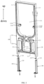
- the embodiment of the disclosure relates to a mounting bracket, which includes a bracket body 100, a locking assembly 200 and a support foot 300.
- the bracket body 100 is used for the installation of component a, the locking assembly 200 is arranged on the bracket body 100, the support foot 300 are arranged on the bracket body 100, the support foot 300 can slide along the up-down direction of the bracket body 100, and the locking assembly 200 can lock the support foot 300 in a preset position.
- the support foot 300 is installed on the ground and used to support the bracket body 100, and the locking assembly 200 can lock the support foot 300 at the preset position, so as to correspondingly adjust the height of the bracket body 100 from the ground, so that the suspension height of the components a installed on the bracket body 100 can be adjusted.
- the locking assembly 200 can lock the support foot 300 in a preset position, and the preset position is the position of the support foot 300 relative to the bracket body 100.
- the bracket body 100 is provided with an accommodation cavity, and the support foot 300 is slidably arranged in the accommodation cavity.
- the support foot 300 can be retracted into the accommodation cavity to reduce the space occupied by the mounting bracket.
- the bracket body 100 includes an integrally formed frame body 110 and an accommodation cylinder 120, the accommodation cylinder 120 is provided with the above accommodation cavity, and the frame body 110 is used for the installation of component a being a water tank component.
- the bracket body 100 is cast in integrated molding, and its appearance surface has better flatness.
- the frame body 110, the accommodation cylinder 120 and the support foot 300 are made of aluminum.
- the surface of aluminum profile will naturally produce a dense oxide layer, so that the mounting bracket can obtain a better corrosion resistance without surface spraying or baking paint and other treatment.
- the support foot 300 is a strip structure, the support foot 300 is provided with a sliding chute 310 extending in the up-down direction, and a guide hole 320 communicated with the sliding chute 310, the guide hole 320 extends in the up-down direction, and the cylinder wall of the accommodation cylinder 120 is provided with a through hole 121 communicated with the accommodation cavity.
- the locking assembly 200 includes a slider 210 and a fastener 220.
- the slider 210 is slidably arranged in the sliding chute 310, the fastener 220 is passed through the through hole 121 and the guide hole 320 in sequence, and the fastener 220 is threaded with the slider 210, wherein the fastener 220 can be arranged as a bolt, etc.
- the slider 210 is a block structure, and the sliding chute 310 cooperates with the slider 210 so that the rotating fastener 220 can drive the slider 210 to move in the direction close to the fastener 220, so that the fastener 220 and the slider 210 together clamp the bracket body 100 and the support foot 300, so as to lock the support foot 300 in the preset position.
- the rotating fastener 220 can also drive the slider 210 to move away from the fastener 22, so that the fastener 220 and the slider 210 no longer clamp the support body 100 and the support foot 300. At this time, the user can drive the support foot 300 to slide relative to the locking assembly 200 to adjust the support foot 300 to another preset position.
- the frame body 110 is a plate-shaped structure, and the surface of the frame body 110 is provided with recessed stiffeners 111.
- the recessed stiffeners 111 arranged on the surface of the frame body 110 can prevent the front and rear bending deformation of the frame body 110; on the other hand, the recessed stiffener 111 can improve the three-dimensional sense of the product.
- the recessed stiffener 111 is a groove wall of a groove arranged on the surface of the frame body 110.
- the back of the frame body 110 has a recessed portion 112 filled with grid stiffeners 112A.
- the grid stiffener 112A located in the recessed portion 112 is reasonably arranged according to the difference of stress characteristics, so that the frame body 110 has both light weight and strength meeting the installation requirements; on the other hand, the main grid point of the grid stiffeners 112 A can be used as the force point of the thimble when the die is out.
- the frame body 110, the accommodation cylinder 120, the recessed stiffener 111 and the grid stiffener 112A are an integrated structure, that is, the bracket body 100 is an integrated casting structure.
- the frame body 110 is provided with a mounting hole 113 for connecting with the mounting part on the corresponding component a.
- the corresponding component a is water tank assembly, toilet parts, drainage pipe fittings, etc.
- the frame body 110 is provided with an avoidance hole 114, the hole wall of the avoidance hole 114 is provided with an extension arm 114A, and the extension arm 114A is used to support the corresponding component a.
- the corresponding component a is the water tank assembly.
- the setting of the extension arm 114 A can improve the connection stability between the corresponding component a and the frame body 110.
- the extension arm 114A is provided with a positioning insert 114a1, which is used for positioning connection with the corresponding component A.
- the corresponding part a is the water tank assembly.
- the corresponding component a can be conveniently positioned and installed on the frame body1 10.
Landscapes
- Engineering & Computer Science (AREA)
- General Engineering & Computer Science (AREA)
- Hydrology & Water Resources (AREA)
- Health & Medical Sciences (AREA)
- Public Health (AREA)
- Water Supply & Treatment (AREA)
- Life Sciences & Earth Sciences (AREA)
- Mechanical Engineering (AREA)
- Legs For Furniture In General (AREA)
- Special Chairs (AREA)
- Sanitary Device For Flush Toilet (AREA)
- Vehicle Step Arrangements And Article Storage (AREA)
- Vehicle Body Suspensions (AREA)
Claims (5)
- Eine Montagehalterung für eine Badezimmerinstallation, wobei die Montagehalterung die folgenden Teile umfasst:einen Halterungskörper (100), der für die Installation einer Wassertankvorrichtung (a);eine Verschlussvorrichtung (200), die am Halterungskörper (100) angebracht ist;einen Stützfuß (300), der am Halterungskörper (100) angebracht ist, wobei der Stützfuß (300) entlang einer Auf-Ab-Richtung des Halterungskörpers (100) gleiten kann und die Verschlussvorrichtung (200) konfiguriert ist, den Stützfuß an seinen voreingestellten Position zu sperren; wobei der Stützfuß (300) mit einer Schieberutsche (310) in der Auf-Ab-Richtung und mit einem Führungsloch (320), das mit der Schieberutsche (310) in Verbindung steht versehen ist, und wobei die Verschlussvorrichtung (200) einen Schieberegler (210) enthält, der verschiebbar an der Schieberutsche (310) angebracht ist;einen Verschluss (220), wobei der Verschluss der Reihe nach durch den Halterungskörper (100) und das Führungsloch (320) führt und der Verschluss (220) mit einem Schieber (210) versehen ist, wobeider Verschluss (220) und der Schieber (210) zusammenarbeiten, um den Stützfuß (300) an seiner voreingestellten Position am Halterungskörper (100) zu sperren; wobeider Halterungskörper (100) mit einem Aufnahmehohlraum versehen ist und der Stützfuß (300) verschiebbar im Aufnahmehohlraum angeordnet ist;der Halterungskörper (100) einen Rahmenkörper (110) und einen Aufnahmezylinder (120) umfasst, der Rahmenkörper und der Aufnahmezylinder einstückig ausgebildet sind, der Aufnahmehohlraum sich im Aufnahmezylinder (120) befindet und der Rahmenkörper (110) für die Installation der Wassertankvorrichtung konfiguriert (a) ist;dadurch gekennzeichnet, dassder Rahmenkörper (110) eine plattenförmige Struktur aufweist und eine Oberfläche des Rahmenkörpers (110) mit einer vertieften Versteifung (111) versehen ist;und eine Rückseite des Rahmenkörpers (110) mit einem vertieften Abschnitt (112) versehen ist, wobei der vertiefte Abschnitt (112) mit Gitterversteifungen (112A) versehen ist.
- Die Montagehalterung nach Anspruch 1, wobei
der Rahmenkörper (110) mit einem Montageloch (113) versehen ist, das für die Verbindung mit einem dem Montageloch entsprechenden Montageteil der Wassertankvorrichtung (a) vorgesehen ist. - Die Montagehalterung nach Anspruch 1, wobei
der Rahmenkörper (110) mit einem Vermeidungsloch (114) versehen ist, eine Lochwand des Vormeidungslochs (114) mit einem Verlängerungsarm (114A) versehen ist und der Verlängerungsarm (114A) konfiguriert ist, die Wassertankvorrichtung (a), die dem Verlängerungsarm entspricht, zu stützen. - Die Montagehalterung nach Anspruch 3, wobei
der Verlängerungsarm (114A) mit einer Positioniereinsatzstütze (114A1) versehen ist und die Positioniereinsatzstütze (114A1) für die Positionierverbindung mit der Wassertankvorrichtung (a), die der Positioniereinsatzstütze entspricht, konfiguriert ist. - Die Montagehalterung nach Anspruch 1, wobei
der Rahmenkörper (110), der Aufnahmezylinder (120) und der Stützfuß (300) aus Aluminium gefertigt sind.
Applications Claiming Priority (1)
| Application Number | Priority Date | Filing Date | Title |
|---|---|---|---|
| CN202122642278.7U CN216339899U (zh) | 2021-10-29 | 2021-10-29 | 一种安装支架 |
Publications (3)
| Publication Number | Publication Date |
|---|---|
| EP4174238A1 EP4174238A1 (de) | 2023-05-03 |
| EP4174238B1 true EP4174238B1 (de) | 2023-09-06 |
| EP4174238C0 EP4174238C0 (de) | 2023-09-06 |
Family
ID=80819681
Family Applications (1)
| Application Number | Title | Priority Date | Filing Date |
|---|---|---|---|
| EP22020112.3A Active EP4174238B1 (de) | 2021-10-29 | 2022-03-16 | Montagerahmen |
Country Status (4)
| Country | Link |
|---|---|
| US (1) | US11965621B2 (de) |
| EP (1) | EP4174238B1 (de) |
| CN (1) | CN216339899U (de) |
| ES (1) | ES2961612T3 (de) |
Family Cites Families (31)
| Publication number | Priority date | Publication date | Assignee | Title |
|---|---|---|---|---|
| DE2457953A1 (de) * | 1974-12-07 | 1976-06-16 | Monta Gmbh & Co Kg | Montageblock fuer wandhaengende wc-becken, urinale o.dgl. |
| DE2637749A1 (de) * | 1976-08-21 | 1978-02-23 | Joachim Seiffert | Einbau-traggeruest fuer hohlkoerperwaende zur befestigung von wandhaengenden sanitaereinrichtungen |
| DE8914494U1 (de) * | 1989-07-07 | 1990-01-25 | Geberit Ag, Jona, St.Gallen | Montagerahmen für die Vorwandinstallation eines Sanitärapparates und insbesondere eines Urinals |
| EP0424560B1 (de) * | 1989-10-24 | 1993-03-03 | Geberit AG | Installationsbaustein für Sanitäreinrichtungen |
| DE9105572U1 (de) * | 1990-06-08 | 1991-07-04 | Geberit Ag, Jona, St.Gallen | Installationsbaustein für eine Sanitäreinrichtung |
| DE4415015A1 (de) * | 1994-04-29 | 1995-11-02 | Albrecht Weis | Hilfsvorrichtung für die Montage eines Wasserklosett-Spülkastens |
| DE19507843A1 (de) * | 1995-03-07 | 1996-09-12 | Mero Werke Kg | Montagevorrichtung zur tragenden Befestigung einer Sanitäreinrichtung |
| DE29619490U1 (de) * | 1996-01-23 | 1997-01-02 | Geberit Technik Ag, Jona | Gestell, insbesondere zur Befestigung von Sanitärapparaten |
| DE29803394U1 (de) * | 1998-02-26 | 1998-05-14 | E. Missel GmbH & Co., 70374 Stuttgart | Spülsystem |
| DE29803307U1 (de) * | 1998-03-02 | 1998-07-02 | Thermconcept Produkte für Heizung und Sanitär GmbH & Co., 48282 Emsdetten | Installationsrahmen für die Vorwandmontage |
| CZ11610U1 (cs) * | 2001-02-08 | 2001-10-04 | Geberit Technik Ag | Přídrľný prvek |
| ITPD20020012U1 (it) * | 2002-02-26 | 2003-08-26 | Fischer Italia Srl Unipersonal | Attrezzatura particolarmente per il supporto di sanitari del tipo sospeso. |
| DE10210494C1 (de) * | 2002-03-11 | 2003-12-11 | Mepa Pauli Und Menden Gmbh | Tragvorrichtung für einen Sanitärkörper |
| GB2401119B (en) * | 2003-04-30 | 2006-07-05 | Polypipe Building Products Ltd | A support frame |
| ITMI20042511A1 (it) * | 2004-12-24 | 2005-03-24 | Oliveira & Irmao Sa | Dispositivo di fissaggio di tubazioni ad una struttura di installazione per sanitari in particolare per un wc con cassetta di risciacquo |
| FR2908141B1 (fr) * | 2006-11-08 | 2011-05-06 | Sanitaire Access Services S A S | Dispositif de raccordement de canalisations pour une installation sanitaire de toilettes du type encastree dans un bâti-support |
| DE102007022019A1 (de) * | 2007-05-08 | 2008-11-13 | GROHEDAL Sanitärsysteme GmbH & Co. KG | Stützfuß für einen Sanitär-Installationsrahmen |
| DK2166163T3 (da) * | 2008-09-17 | 2013-04-29 | Geberit Int Ag | Montageindretning til en WC-kumme |
| FR2942817B1 (fr) * | 2009-03-04 | 2016-11-25 | Siamp Cedap Reunies | Cuvette de toilette reglable en hauteur |
| ES2401888B9 (es) * | 2011-09-21 | 2014-10-14 | Fominaya, S.A. | Bastidor empotrable para sujeción de elementos sanitarios y su proceso de fabricación |
| GB2500421B (en) * | 2012-03-22 | 2016-05-11 | Dudley Thomas Ltd | Adjustable frame for mounting a cistern |
| DE102013203941A1 (de) * | 2013-03-07 | 2014-09-11 | Tece Gmbh | Leitungsführungseinrichtung für einen Installationsblock und Installationsblock mit Leitungsführungseinrichtung |
| DE102014109276B4 (de) * | 2014-07-02 | 2016-04-07 | Tece Gmbh | WC-Modul mit Unterputzspülkasten für ein Dusch-WC mit integriertem, abgesichertem Frischwasseranschluss |
| FR3034788B1 (fr) * | 2015-04-10 | 2017-04-14 | Siamp Cedap Reunies | Structure de support pour un equipement de toilettes suspendues |
| CN108374466B (zh) * | 2017-01-30 | 2020-07-14 | Toto株式会社 | 壁挂式便器用安装装置以及冲厕系统 |
| DE102017003823A1 (de) * | 2017-04-20 | 2018-10-25 | GROHEDAL Sanitärsysteme GmbH | Sanitärinstallationssystem mit einem modularen Funktionssystem |
| IT201700082164A1 (it) * | 2017-07-19 | 2019-01-19 | Valsir Spa | Dispositivo di installazione per una struttura di montaggio di apparecchi sanitari e suo uso in un metodo di installazione di una struttura di montaggio di apparecchi sanitari |
| DE202018001327U1 (de) * | 2017-08-22 | 2018-11-27 | Geberit International Ag | Behältnis zum abgedichteten Einbau in eine Wand |
| DE102017009631A1 (de) * | 2017-10-16 | 2019-04-18 | GROHEDAL Sanitärsysteme GmbH | Vorrichtung zur Befestigung eines WCs an einer Wand und WC-Anordnung mit einer entsprechenden Vorrichtung |
| DE202020003130U1 (de) * | 2020-07-21 | 2020-08-21 | Sanitärtechnik Eisenberg GmbH | Bauschutz und Vorwandelement mit Bauschutz |
| DE102020128131A1 (de) * | 2020-10-26 | 2022-04-28 | Tece Gmbh | Montagemodul |
-
2021
- 2021-10-29 CN CN202122642278.7U patent/CN216339899U/zh active Active
-
2022
- 2022-03-16 ES ES22020112T patent/ES2961612T3/es active Active
- 2022-03-16 US US17/695,840 patent/US11965621B2/en active Active
- 2022-03-16 EP EP22020112.3A patent/EP4174238B1/de active Active
Also Published As
| Publication number | Publication date |
|---|---|
| US11965621B2 (en) | 2024-04-23 |
| CN216339899U (zh) | 2022-04-19 |
| ES2961612T3 (es) | 2024-03-12 |
| EP4174238A1 (de) | 2023-05-03 |
| EP4174238C0 (de) | 2023-09-06 |
| US20230138187A1 (en) | 2023-05-04 |
Similar Documents
| Publication | Publication Date | Title |
|---|---|---|
| EP2740849B1 (de) | Einbaurahmen zur fixierung von toilettenelementen, herstellungsverfahren und verwendung des besagten rahmens | |
| DE9216799U1 (de) | Rahmenförmige Haltevorrichtung für die Vorwandmontage von sanitären Gegenständen (Waschtische, WC, o.ä.) und deren Anschlußleitungen | |
| US7571497B2 (en) | Lavatory carrier | |
| EP2642034A2 (de) | Einstellbare Rahmen | |
| CN115003891B (zh) | 用于设置和安装盥洗盆的装置 | |
| JP2017110388A (ja) | 取付部材の取付構造 | |
| CN206809218U (zh) | 可调沐浴用品架 | |
| CN2538857Y (zh) | 卫生间台下盆的支撑架 | |
| CN219109036U (zh) | 一种横插式卡扣橱柜可调脚 | |
| US20230138187A1 (en) | Mounting bracket | |
| CZ66096A3 (en) | Front panel wall, particularly for sanitary installation | |
| SK1982002A3 (en) | Wall support on a mounting frame for sanitary apparatuses | |
| CN219306289U (zh) | 一种可调的浴室柜暗装装置 | |
| CN106691267A (zh) | 可调高度的沐浴用品架 | |
| JP3641610B2 (ja) | カウンターの取付構造及びカウンター | |
| JP3589627B2 (ja) | カウンターの取付構造 | |
| CN214964382U (zh) | 一种便于固定的墙面挂件 | |
| JP3589628B2 (ja) | カウンターの取付構造 | |
| JPH0354640Y2 (de) | ||
| CZ65996A3 (en) | Front panel wall | |
| JPH10179301A (ja) | 棚 | |
| CZ294841B6 (cs) | Profilová kolejnice a spojovací prvek pro nosné zařízení | |
| CN216974220U (zh) | 一种板厚控制器 | |
| CN214157152U (zh) | 一种支架 | |
| JPS5925252Y2 (ja) | 吊戸棚 |
Legal Events
| Date | Code | Title | Description |
|---|---|---|---|
| PUAI | Public reference made under article 153(3) epc to a published international application that has entered the european phase |
Free format text: ORIGINAL CODE: 0009012 |
|
| STAA | Information on the status of an ep patent application or granted ep patent |
Free format text: STATUS: REQUEST FOR EXAMINATION WAS MADE |
|
| 17P | Request for examination filed |
Effective date: 20220317 |
|
| AK | Designated contracting states |
Kind code of ref document: A1 Designated state(s): AL AT BE BG CH CY CZ DE DK EE ES FI FR GB GR HR HU IE IS IT LI LT LU LV MC MK MT NL NO PL PT RO RS SE SI SK SM TR |
|
| GRAP | Despatch of communication of intention to grant a patent |
Free format text: ORIGINAL CODE: EPIDOSNIGR1 |
|
| STAA | Information on the status of an ep patent application or granted ep patent |
Free format text: STATUS: GRANT OF PATENT IS INTENDED |
|
| INTG | Intention to grant announced |
Effective date: 20230526 |
|
| GRAS | Grant fee paid |
Free format text: ORIGINAL CODE: EPIDOSNIGR3 |
|
| GRAA | (expected) grant |
Free format text: ORIGINAL CODE: 0009210 |
|
| STAA | Information on the status of an ep patent application or granted ep patent |
Free format text: STATUS: THE PATENT HAS BEEN GRANTED |
|
| RIN1 | Information on inventor provided before grant (corrected) |
Inventor name: LIANG, WEINAN Inventor name: MA, JIAFU Inventor name: HUANG, HAOJIA Inventor name: ZHANG, HAI Inventor name: ZHOU, WENHUI |
|
| AK | Designated contracting states |
Kind code of ref document: B1 Designated state(s): AL AT BE BG CH CY CZ DE DK EE ES FI FR GB GR HR HU IE IS IT LI LT LU LV MC MK MT NL NO PL PT RO RS SE SI SK SM TR |
|
| REG | Reference to a national code |
Ref country code: GB Ref legal event code: FG4D |
|
| REG | Reference to a national code |
Ref country code: CH Ref legal event code: EP |
|
| REG | Reference to a national code |
Ref country code: IE Ref legal event code: FG4D |
|
| REG | Reference to a national code |
Ref country code: DE Ref legal event code: R096 Ref document number: 602022000419 Country of ref document: DE |
|
| U01 | Request for unitary effect filed |
Effective date: 20230919 |
|
| U07 | Unitary effect registered |
Designated state(s): AT BE BG DE DK EE FI FR IT LT LU LV MT NL PT SE SI Effective date: 20230927 |
|
| PG25 | Lapsed in a contracting state [announced via postgrant information from national office to epo] |
Ref country code: GR Free format text: LAPSE BECAUSE OF FAILURE TO SUBMIT A TRANSLATION OF THE DESCRIPTION OR TO PAY THE FEE WITHIN THE PRESCRIBED TIME-LIMIT Effective date: 20231207 |
|
| PG25 | Lapsed in a contracting state [announced via postgrant information from national office to epo] |
Ref country code: RS Free format text: LAPSE BECAUSE OF FAILURE TO SUBMIT A TRANSLATION OF THE DESCRIPTION OR TO PAY THE FEE WITHIN THE PRESCRIBED TIME-LIMIT Effective date: 20230906 Ref country code: NO Free format text: LAPSE BECAUSE OF FAILURE TO SUBMIT A TRANSLATION OF THE DESCRIPTION OR TO PAY THE FEE WITHIN THE PRESCRIBED TIME-LIMIT Effective date: 20231206 Ref country code: HR Free format text: LAPSE BECAUSE OF FAILURE TO SUBMIT A TRANSLATION OF THE DESCRIPTION OR TO PAY THE FEE WITHIN THE PRESCRIBED TIME-LIMIT Effective date: 20230906 Ref country code: GR Free format text: LAPSE BECAUSE OF FAILURE TO SUBMIT A TRANSLATION OF THE DESCRIPTION OR TO PAY THE FEE WITHIN THE PRESCRIBED TIME-LIMIT Effective date: 20231207 |
|
| REG | Reference to a national code |
Ref country code: ES Ref legal event code: FG2A Ref document number: 2961612 Country of ref document: ES Kind code of ref document: T3 Effective date: 20240312 |
|
| PG25 | Lapsed in a contracting state [announced via postgrant information from national office to epo] |
Ref country code: IS Free format text: LAPSE BECAUSE OF FAILURE TO SUBMIT A TRANSLATION OF THE DESCRIPTION OR TO PAY THE FEE WITHIN THE PRESCRIBED TIME-LIMIT Effective date: 20240106 |
|
| U20 | Renewal fee for the european patent with unitary effect paid |
Year of fee payment: 3 Effective date: 20240318 |
|
| PG25 | Lapsed in a contracting state [announced via postgrant information from national office to epo] |
Ref country code: SM Free format text: LAPSE BECAUSE OF FAILURE TO SUBMIT A TRANSLATION OF THE DESCRIPTION OR TO PAY THE FEE WITHIN THE PRESCRIBED TIME-LIMIT Effective date: 20230906 Ref country code: RO Free format text: LAPSE BECAUSE OF FAILURE TO SUBMIT A TRANSLATION OF THE DESCRIPTION OR TO PAY THE FEE WITHIN THE PRESCRIBED TIME-LIMIT Effective date: 20230906 Ref country code: IS Free format text: LAPSE BECAUSE OF FAILURE TO SUBMIT A TRANSLATION OF THE DESCRIPTION OR TO PAY THE FEE WITHIN THE PRESCRIBED TIME-LIMIT Effective date: 20240106 Ref country code: CZ Free format text: LAPSE BECAUSE OF FAILURE TO SUBMIT A TRANSLATION OF THE DESCRIPTION OR TO PAY THE FEE WITHIN THE PRESCRIBED TIME-LIMIT Effective date: 20230906 Ref country code: SK Free format text: LAPSE BECAUSE OF FAILURE TO SUBMIT A TRANSLATION OF THE DESCRIPTION OR TO PAY THE FEE WITHIN THE PRESCRIBED TIME-LIMIT Effective date: 20230906 |
|
| PG25 | Lapsed in a contracting state [announced via postgrant information from national office to epo] |
Ref country code: PL Free format text: LAPSE BECAUSE OF FAILURE TO SUBMIT A TRANSLATION OF THE DESCRIPTION OR TO PAY THE FEE WITHIN THE PRESCRIBED TIME-LIMIT Effective date: 20230906 |
|
| REG | Reference to a national code |
Ref country code: DE Ref legal event code: R097 Ref document number: 602022000419 Country of ref document: DE |
|
| PLBE | No opposition filed within time limit |
Free format text: ORIGINAL CODE: 0009261 |
|
| STAA | Information on the status of an ep patent application or granted ep patent |
Free format text: STATUS: NO OPPOSITION FILED WITHIN TIME LIMIT |
|
| 26N | No opposition filed |
Effective date: 20240607 |
|
| PG25 | Lapsed in a contracting state [announced via postgrant information from national office to epo] |
Ref country code: MC Free format text: LAPSE BECAUSE OF FAILURE TO SUBMIT A TRANSLATION OF THE DESCRIPTION OR TO PAY THE FEE WITHIN THE PRESCRIBED TIME-LIMIT Effective date: 20230906 |
|
| PG25 | Lapsed in a contracting state [announced via postgrant information from national office to epo] |
Ref country code: MC Free format text: LAPSE BECAUSE OF FAILURE TO SUBMIT A TRANSLATION OF THE DESCRIPTION OR TO PAY THE FEE WITHIN THE PRESCRIBED TIME-LIMIT Effective date: 20230906 |
|
| PG25 | Lapsed in a contracting state [announced via postgrant information from national office to epo] |
Ref country code: IE Free format text: LAPSE BECAUSE OF NON-PAYMENT OF DUE FEES Effective date: 20240316 |
|
| PG25 | Lapsed in a contracting state [announced via postgrant information from national office to epo] |
Ref country code: IE Free format text: LAPSE BECAUSE OF NON-PAYMENT OF DUE FEES Effective date: 20240316 |
|
| U20 | Renewal fee for the european patent with unitary effect paid |
Year of fee payment: 4 Effective date: 20250226 |
|
| PGFP | Annual fee paid to national office [announced via postgrant information from national office to epo] |
Ref country code: ES Payment date: 20250404 Year of fee payment: 4 |
|
| PG25 | Lapsed in a contracting state [announced via postgrant information from national office to epo] |
Ref country code: CY Free format text: LAPSE BECAUSE OF FAILURE TO SUBMIT A TRANSLATION OF THE DESCRIPTION OR TO PAY THE FEE WITHIN THE PRESCRIBED TIME-LIMIT; INVALID AB INITIO Effective date: 20220316 |
|
| REG | Reference to a national code |
Ref country code: CH Ref legal event code: H13 Free format text: ST27 STATUS EVENT CODE: U-0-0-H10-H13 (AS PROVIDED BY THE NATIONAL OFFICE) Effective date: 20251023 |
|
| PG25 | Lapsed in a contracting state [announced via postgrant information from national office to epo] |
Ref country code: TR Free format text: LAPSE BECAUSE OF FAILURE TO SUBMIT A TRANSLATION OF THE DESCRIPTION OR TO PAY THE FEE WITHIN THE PRESCRIBED TIME-LIMIT Effective date: 20230906 |
|
| PG25 | Lapsed in a contracting state [announced via postgrant information from national office to epo] |
Ref country code: CH Free format text: LAPSE BECAUSE OF NON-PAYMENT OF DUE FEES Effective date: 20250331 |
|
| U20 | Renewal fee for the european patent with unitary effect paid |
Year of fee payment: 5 Effective date: 20260214 |
|
| PGFP | Annual fee paid to national office [announced via postgrant information from national office to epo] |
Ref country code: GB Payment date: 20260226 Year of fee payment: 5 |