EP4174280A1 - Ensemble d'une section de fenêtre et d'un dispositif d'écran - Google Patents
Ensemble d'une section de fenêtre et d'un dispositif d'écran Download PDFInfo
- Publication number
- EP4174280A1 EP4174280A1 EP22202406.9A EP22202406A EP4174280A1 EP 4174280 A1 EP4174280 A1 EP 4174280A1 EP 22202406 A EP22202406 A EP 22202406A EP 4174280 A1 EP4174280 A1 EP 4174280A1
- Authority
- EP
- European Patent Office
- Prior art keywords
- profile
- screen
- assembly
- window
- side wall
- Prior art date
- Legal status (The legal status is an assumption and is not a legal conclusion. Google has not performed a legal analysis and makes no representation as to the accuracy of the status listed.)
- Granted
Links
Images


Classifications
-
- E—FIXED CONSTRUCTIONS
- E06—DOORS, WINDOWS, SHUTTERS, OR ROLLER BLINDS IN GENERAL; LADDERS
- E06B—FIXED OR MOVABLE CLOSURES FOR OPENINGS IN BUILDINGS, VEHICLES, FENCES OR LIKE ENCLOSURES IN GENERAL, e.g. DOORS, WINDOWS, BLINDS, GATES
- E06B1/00—Border constructions of openings in walls, floors, or ceilings; Frames to be rigidly mounted in such openings
- E06B1/62—Tightening or covering joints between the border of openings and the frame or between contiguous frames
- E06B1/68—Tightening or covering joints between the border of openings and the frame or between contiguous frames by profiled external parts
-
- E—FIXED CONSTRUCTIONS
- E06—DOORS, WINDOWS, SHUTTERS, OR ROLLER BLINDS IN GENERAL; LADDERS
- E06B—FIXED OR MOVABLE CLOSURES FOR OPENINGS IN BUILDINGS, VEHICLES, FENCES OR LIKE ENCLOSURES IN GENERAL, e.g. DOORS, WINDOWS, BLINDS, GATES
- E06B9/00—Screening or protective devices for wall or similar openings, with or without operating or securing mechanisms; Closures of similar construction
- E06B9/56—Operating, guiding or securing devices or arrangements for roll-type closures; Spring drums; Tape drums; Counterweighting arrangements therefor
- E06B9/58—Guiding devices
-
- E—FIXED CONSTRUCTIONS
- E06—DOORS, WINDOWS, SHUTTERS, OR ROLLER BLINDS IN GENERAL; LADDERS
- E06B—FIXED OR MOVABLE CLOSURES FOR OPENINGS IN BUILDINGS, VEHICLES, FENCES OR LIKE ENCLOSURES IN GENERAL, e.g. DOORS, WINDOWS, BLINDS, GATES
- E06B1/00—Border constructions of openings in walls, floors, or ceilings; Frames to be rigidly mounted in such openings
- E06B1/62—Tightening or covering joints between the border of openings and the frame or between contiguous frames
- E06B1/64—Tightening or covering joints between the border of openings and the frame or between contiguous frames by loosely-inserted means, e.g. strip, resilient tongue
-
- E—FIXED CONSTRUCTIONS
- E06—DOORS, WINDOWS, SHUTTERS, OR ROLLER BLINDS IN GENERAL; LADDERS
- E06B—FIXED OR MOVABLE CLOSURES FOR OPENINGS IN BUILDINGS, VEHICLES, FENCES OR LIKE ENCLOSURES IN GENERAL, e.g. DOORS, WINDOWS, BLINDS, GATES
- E06B3/00—Window sashes, door leaves, or like elements for closing wall or like openings; Layout of fixed or moving closures, e.g. windows in wall or like openings; Features of rigidly-mounted outer frames relating to the mounting of wing frames
- E06B3/04—Wing frames not characterised by the manner of movement
- E06B3/26—Compound frames, i.e. one frame within or behind another
- E06B3/2605—Compound frames, i.e. one frame within or behind another with frames permanently mounted behind or within each other, each provided with a pane or screen
- E06B2003/2615—Frames made of metal
-
- E—FIXED CONSTRUCTIONS
- E06—DOORS, WINDOWS, SHUTTERS, OR ROLLER BLINDS IN GENERAL; LADDERS
- E06B—FIXED OR MOVABLE CLOSURES FOR OPENINGS IN BUILDINGS, VEHICLES, FENCES OR LIKE ENCLOSURES IN GENERAL, e.g. DOORS, WINDOWS, BLINDS, GATES
- E06B3/00—Window sashes, door leaves, or like elements for closing wall or like openings; Layout of fixed or moving closures, e.g. windows in wall or like openings; Features of rigidly-mounted outer frames relating to the mounting of wing frames
- E06B3/04—Wing frames not characterised by the manner of movement
- E06B3/263—Frames with special provision for insulation
- E06B3/2632—Frames with special provision for insulation with arrangements reducing the heat transmission, other than an interruption in a metal section
- E06B2003/26325—Frames with special provision for insulation with arrangements reducing the heat transmission, other than an interruption in a metal section the convection or radiation in a hollow space being reduced, e.g. by subdividing the hollow space
- E06B2003/2633—Frames with special provision for insulation with arrangements reducing the heat transmission, other than an interruption in a metal section the convection or radiation in a hollow space being reduced, e.g. by subdividing the hollow space the insulating strips between the metal sections having ribs extending into the hollow space
-
- E—FIXED CONSTRUCTIONS
- E06—DOORS, WINDOWS, SHUTTERS, OR ROLLER BLINDS IN GENERAL; LADDERS
- E06B—FIXED OR MOVABLE CLOSURES FOR OPENINGS IN BUILDINGS, VEHICLES, FENCES OR LIKE ENCLOSURES IN GENERAL, e.g. DOORS, WINDOWS, BLINDS, GATES
- E06B3/00—Window sashes, door leaves, or like elements for closing wall or like openings; Layout of fixed or moving closures, e.g. windows in wall or like openings; Features of rigidly-mounted outer frames relating to the mounting of wing frames
- E06B3/04—Wing frames not characterised by the manner of movement
- E06B3/263—Frames with special provision for insulation
- E06B2003/26349—Details of insulating strips
- E06B2003/26387—Performing extra functions
- E06B2003/26389—Holding sealing strips or forming sealing abutments
-
- E—FIXED CONSTRUCTIONS
- E06—DOORS, WINDOWS, SHUTTERS, OR ROLLER BLINDS IN GENERAL; LADDERS
- E06B—FIXED OR MOVABLE CLOSURES FOR OPENINGS IN BUILDINGS, VEHICLES, FENCES OR LIKE ENCLOSURES IN GENERAL, e.g. DOORS, WINDOWS, BLINDS, GATES
- E06B9/00—Screening or protective devices for wall or similar openings, with or without operating or securing mechanisms; Closures of similar construction
- E06B9/56—Operating, guiding or securing devices or arrangements for roll-type closures; Spring drums; Tape drums; Counterweighting arrangements therefor
- E06B9/58—Guiding devices
- E06B2009/587—Mounting of guiding devices to supporting structure
-
- E—FIXED CONSTRUCTIONS
- E06—DOORS, WINDOWS, SHUTTERS, OR ROLLER BLINDS IN GENERAL; LADDERS
- E06B—FIXED OR MOVABLE CLOSURES FOR OPENINGS IN BUILDINGS, VEHICLES, FENCES OR LIKE ENCLOSURES IN GENERAL, e.g. DOORS, WINDOWS, BLINDS, GATES
- E06B3/00—Window sashes, door leaves, or like elements for closing wall or like openings; Layout of fixed or moving closures, e.g. windows in wall or like openings; Features of rigidly-mounted outer frames relating to the mounting of wing frames
- E06B3/04—Wing frames not characterised by the manner of movement
- E06B3/263—Frames with special provision for insulation
- E06B3/26301—Frames with special provision for insulation with prefabricated insulating strips between two metal section members
- E06B3/26303—Frames with special provision for insulation with prefabricated insulating strips between two metal section members with thin strips, e.g. defining a hollow space between the metal section members
-
- E—FIXED CONSTRUCTIONS
- E06—DOORS, WINDOWS, SHUTTERS, OR ROLLER BLINDS IN GENERAL; LADDERS
- E06B—FIXED OR MOVABLE CLOSURES FOR OPENINGS IN BUILDINGS, VEHICLES, FENCES OR LIKE ENCLOSURES IN GENERAL, e.g. DOORS, WINDOWS, BLINDS, GATES
- E06B3/00—Window sashes, door leaves, or like elements for closing wall or like openings; Layout of fixed or moving closures, e.g. windows in wall or like openings; Features of rigidly-mounted outer frames relating to the mounting of wing frames
- E06B3/04—Wing frames not characterised by the manner of movement
- E06B3/263—Frames with special provision for insulation
- E06B3/26347—Frames with special provision for insulation specially adapted for sliding doors or windows
-
- E—FIXED CONSTRUCTIONS
- E06—DOORS, WINDOWS, SHUTTERS, OR ROLLER BLINDS IN GENERAL; LADDERS
- E06B—FIXED OR MOVABLE CLOSURES FOR OPENINGS IN BUILDINGS, VEHICLES, FENCES OR LIKE ENCLOSURES IN GENERAL, e.g. DOORS, WINDOWS, BLINDS, GATES
- E06B9/00—Screening or protective devices for wall or similar openings, with or without operating or securing mechanisms; Closures of similar construction
- E06B9/24—Screens or other constructions affording protection against light, especially against sunshine; Similar screens for privacy or appearance; Slat blinds
- E06B9/40—Roller blinds
- E06B9/42—Parts or details of roller blinds, e.g. suspension devices, blind boxes
Definitions
- the present invention relates to an assembly of a window section, comprising a window profile assembly, for forming a window frame for mounting glazing to form the window section and a screen device, comprising a screen profile assembly, comprising a screen holding profile for mounting a lateral side of a screen in order to screen off the window section, the screen profile assembly comprising a basic profile for mounting the screen profile assembly against the window section, wherein this basic profile comprises a side wall, which is intended to be applied on the window section for fastening the basic profile against the window section and comprises a rear wall, which is raised relative to the side wall in order to be raised relative to the window section, wherein the window section, viewed in a transverse direction transverse to the rear wall, comprises a nominal transverse frame outside dimension and the screen device comprises, in the transverse direction, a nominal transverse screen outside dimension, wherein the rear wall of the basic profile comprises a reference line, which is provided in order to delimit this nominal transverse screen outside dimension and wherein the nominal transverse frame outside dimension is equal to the nominal trans
- the window profile assembly of said profile assembly comprises window profiles that are assembled to form a window frame, which is intended for the mounting of glazing.
- a window frame of this kind is also suitable for and is also often used for mounting for example panels or grilles, etc. Whenever glazing is mentioned, this also applies mutatis mutandis to any other suitable wall elements.
- a window section is intended to mean both separate windows or doors and walls with various windows and/or doors installed adjacent to each other.
- the screen profile assembly is provided for mounting a lateral side of a screen in order to screen off this window section.
- a screen of this kind may assume various forms.
- a screen device of which this screen and this screen profile assembly form part may for example comprise a screen that is windable and unwindable on a cloth roller, which may be configured as an insect screen or as a blackout curtain, etc., and wherein the cloth roller is then typically installed in a screen housing.
- Examples of screen profile assemblies wherein a side wall of a basic profile of this screen profile assembly is applied against a window section for fastening the basic profile against the window section are for example described and illustrated in BE 1 018 779 A5 .
- various fastening methods and associated fasteners are described for mounting a screen profile assembly against a window section.
- a screen profile assembly with a screen guide profile for guiding a roller shutter is secured to a window section.
- a screen guide profile for guiding a lateral side of a roller shutter is secured by means of a suitable window profile to a window section.
- the screen profile assemblies are fastened to window profiles of a window section of this kind. There is a tendency to make these window profiles narrower and narrower, viewed in the transverse direction, in so-called minimalistic window sections. Then it is also desired to join the screen profile assemblies in this transverse direction just as narrowly on these window profiles by also making said side wall of the basic profile just as narrow. Thus, there is less and less space for fastening a screen profile assembly of this kind in a sturdy manner against these window profiles. It is difficult to fit other fasteners for example such as screws on the width of these side walls, for example such as is the case in DE 297 08 747 U1 . Thus, in practice, often screen profile assemblies are fastened to window profiles, which are made wider in the transverse direction than these window profiles.
- the present invention relates to assemblies wherein the nominal window outside dimension is equal to the nominal screen outside dimension.
- the width of the window section is equal to the width of the screen device.
- the window profiles and profiles of the screen profile assembly will then be given desired dimensions or be sawn to a desired dimension to achieve this aim.
- the width obtained in the transverse direction will in practice, however, typically deviate somewhat from this desired nominal window outside dimension.
- the width obtained for a screen device in the transverse direction will in practice, through assembly of the components thereof, deviate somewhat from the desired nominal screen outside dimension.
- the outside dimensions of a joinery element according to these specifications may not deviate by more than about 1.5 mm up to 1 metre of outside dimension relative to the nominal dimensions and by not more than about 2 mm for joinery elements with larger dimensions than 1 metre outside dimension.
- the transverse frame outside dimension should thus remain within ⁇ 1.5 mm of the nominal transverse frame outside dimension.
- the transverse frame tolerance is then 1.5 mm.
- this transverse frame outside dimension should remain within ⁇ 2 mm of the nominal transverse frame outside dimension.
- the transverse frame tolerance is then 2 mm.
- the transverse screen outside dimension should remain within ⁇ 1.5 mm of the nominal transverse screen outside dimension and for a nominal transverse screen outside dimension that is greater than 1 metre, it should remain within ⁇ 2 mm of the nominal transverse screen outside dimension.
- the transverse screen tolerance is then 1.5 mm and 2 mm respectively.
- the transverse screen outside dimension is less than the nominal transverse screen outside dimension and/or the transverse frame outside dimension is greater than the nominal transverse frame outside dimension, it is not then possible to mount this screen device against the window section.
- the aim of the present invention is to provide a screen profile assembly of this kind which, taking into account permitted dimensional tolerances, is fastenable in an aesthetic, but also sturdy manner on minimalistic window sections and moreover is able to transmit the necessary forces on this window section.
- This aim of the invention is achieved by providing an assembly of a window section, comprising a window profile assembly for forming a window frame for mounting glazing, to form the window section, and a screen device, comprising a screen profile assembly, comprising a screen holding profile for mounting a lateral side of a screen in order to screen off the window section, and comprising a basic profile for mounting the screen profile assembly against the window section, wherein this basic profile:
- profiles of a screen profile assembly of this kind and more specifically said basic profile are then preferably manufactured in aluminium, for example by extrusion.
- narrower window profiles are typically also made deeper, in this direction there is sufficient space with these window profiles to fasten a flange against it here.
- the side wall can be made narrower.
- the side wall can then also be made narrow, so that in contrast to the basic profile from DE 297 08 747 U1 , it is no longer possible to fit screws through this side wall for fastening the basic profile.
- the basic profile is then only fastened to the window section by means of screws through the flange.
- a screen profile assembly of this kind can be connected in an aesthetic manner to a narrow window profile in a minimalistic window section.
- the solution according to the present invention is also useful with window sections that are not minimalistic. With a narrower side wall, there is free space next to this side wall for mounting additional frame elements, for example such as an insect screen. With lifting and sash windows, alongside said narrower side wall there is extra space for movable parts of the window section.
- the flange is mounted displaced from the side wall by a distance ⁇ d relative to the reference line, with 0 ⁇ ⁇ d ⁇ the transverse frame tolerance.
- ⁇ d the transverse frame tolerance
- the transverse frame outside dimension may deviate by about 2 mm from the nominal transverse frame outside dimension.
- a screen device of which the screen profile assembly forms a part, is typically also provided with a screen housing in which a roll-up/roll-down screen is housed.
- This screen housing may also deviate by about 2 mm from the transverse screen outside dimension.
- Said screen profile assemblies are typically mounted on either side of the screen adjacent to and under this screen housing.
- the distance pieces may be fitted between the flanges of the screen profile assemblies on either side of the screen device and the respective window profiles.
- On either side for example 4 plates of 1 mm are then required as distance pieces, which compensate 8 mm in total.
- 2 plates of 1 mm should be fitted as distance pieces on either side, which compensate 4 mm in total. In this way, ⁇ 4 mm may thus be compensated.
- the ⁇ d makes this all possible.
- the side wall is preferably of flat configuration on the side of the flange next to the aforementioned flange and is preferably free from further projecting parts to allow maximum abutment to the window section and thus be able to transmit the necessary forces, without having to make the side wall wider in the transverse direction.
- the side wall has a dimension (width) that is less than the distance (height) by which the flange is raised relative to the side wall.
- the side wall in the transverse direction has a width that is less than 30 mm. Even more preferably this width is less than or equal to 25 mm.
- the flange In order to fasten the flange to the window section, the flange is preferably provided with screw holes for fastening the basic profile to the window section by means of screws.
- These screw holes are preferably provided in such a way that screws fitted therein extend roughly parallel to the side wall.
- the flange is more preferably provided, on its side away from the side wall, with grooves for positioning screws for fastening the basic profile to the window section. Said grooves preferably extend roughly parallel to the side wall.
- a screen profile assembly of an assembly according to the invention is preferably provided with a seal, in order to form a moisture barrier between the basic profile and the window section.
- Said seal is preferably configured as an elastic sealing element.
- Said seal meets the ARGE guideline that is applicable in DACH countries.
- Said seal can stop water when the side wall, under the influence of forces that act upon the screen profile assembly, tends to come loose from the window section. Wind-driven rain could otherwise penetrate between the basic profile and the underlying window section.
- sealant would be applied along the edges of said basic profile.
- a seal as mentioned above is preferably integrated in the basic profile, so that no additional sealing has to be applied manually.
- the basic profile may be provided with a slot in order to form a moisture barrier between the basic profile and the window section.
- the basic profile is preferably provided with both a slot and a seal, wherein the seal is fitted in this slot.
- the seal preferably extends over the full depth of the slot and preferably also projects relative to the slot.
- the slot preferably comprises a substantially C-shaped cross-section.
- the seal itself may more specifically comprise a substantially round cross-section.
- the seal and the optional slot for fastening this seal may be mounted on or in the side wall.
- the profiles of a screen profile assembly of an assembly according to the invention preferably define together a mounting opening, through which the screen extends in the installed state.
- This mounting opening is preferably provided in a front wall of the screen profile assembly, which is mounted on the side of the screen profile assembly opposite to the side of the screen profile assembly where the rear wall of the basic profile is installed.
- the rear wall of the basic profile then preferably also forms the rear wall of the screen profile assembly.
- the basic profile of the screen profile assembly is intended to be fastened against a window profile of the window profile assembly, for mounting the screen profile assembly against the window section that is formed by means of this window profile assembly.
- the basic profile of the screen profile assembly should then be mounted on this window profile before this window profile is brought ino a building in which the window section is installed, so that the flange can extend between the window profile and an adjacent building element (a wall of the building or an adjacent installed window profile).
- the side wall more preferably comprises a contact surface that is fitted against a corresponding contact surface of the window profile assembly. Both contact surfaces are then preferably of flat configuration and preferably free from projecting parts, to allow maximum abutment of the side wall to this window profile.
- the window profile assembly of an assembly according to the present invention comprises aluminium profiles
- these will be provided with one or more thermal breaks.
- the flange then preferably projects relative to the side wall by a distance that is less than or equal to the distance over which the thermal break of the aforementioned thermal breaks that is mounted closest to the side wall extends relative to the side wall. Even more preferably, the flange projects relative to the side wall by a distance that is less than said intermediate distance of the side wall from said thermal break that is mounted closest to the side wall.
- An assembly according to the present invention preferably comprises distance pieces, for fastening the basic profile against the window section when securing the flange on the window profile assembly, so as to be able to fasten one or more of these distance pieces between the flange and the window profile assembly, where necessary.
- Said distance piece further comprises at least one basic body, which is intended to extend in the installed state between the flange and the window profile assembly.
- the basic body preferably has a dimension (height) corresponding to the distance (height) by which the flange projects relative to the side wall. This height of the basic body is preferably equal to this height of the flange, so that an installer, when fitting the basic body between the flange and the window profile assembly, knows that the distance piece is fitted deeply enough when the basic body is located completely between the flange and the window profile assembly and does not extend farther from the side wall than the flange.
- the assembly may moreover more specifically comprise screws for fastening the flange on the window profile assembly.
- the basic body is then preferably provided with a slot with barbs, for receiving an aforementioned screw herein for fixation of this distance piece relative to this screw.
- each distance piece may also comprise an engaging element that is intended to extend in the installed state farther from the side wall than the flange, so as to be able to engage on this engaging element in order to fasten it between the flange and the window profile assembly.
- the basic body is preferably of compression-resistant construction. To avoid cold bridges, preferably the distance pieces are not or are only slightly heat-conducting.
- the assemblies (1) illustrated according to the present invention comprise in each case:
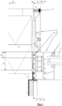
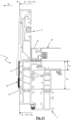
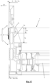
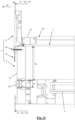
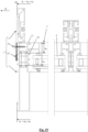
- the window profile assembly (3) may assume several forms, as can be seen in Figs. 1 and 11-15 , for example such as a window profile assembly (3) for a fixed window (5) or several adjacent fixed windows (5) (see Fig. 1 ), a window profile assembly (3) for an opening window (5) (see Fig. 11 ) or a window profile assembly (3) for sash windows (see Figs. 12-14 ). These may optionally be of minimalistic configuration (see Fig. 12 ).
- the window profile assemblies (3) shown comprise several profiles (21) made of aluminium, between which thermal breaks (36) are fitted.
- the screen device is a screen device with a roll-up/roll-down screen that is gripped on both lateral sides in a screen profile assembly (2).
- This roll-up/roll-down screen can be mounted rotatably in a screen housing of the screen device.
- the two screen profile assemblies (2) in each case only one of the two screen profile assemblies (2) is shown.
- the other one of the two screen profile assemblies (2) is configured as the mirror image of the screen profile assembly (2) that is shown.
- the screen may be installed fixed and then a screen profile assembly (2) may be installed on each side of this screen to grip the respective side of the screen.
- the screen profile assembly (2) comprises in each case a basic profile (6) for mounting the screen profile assembly (2) against the window section (5).
- a basic profile (6) may be configured per se as a so-called screen profile assembly (2) and then serves as a so-called screen holding profile. Besides this basic profile (6), this screen profile assembly (2) may, however, also comprise one or more additional profiles (15, 16, 17, 18), including for example a so-called screen holding profile (17).
- the screen profile assembly (2) comprises, besides the basic profile (6), an insert profile (15), which is mountable in a cavity (26) provided for this purpose, and a securing profile (16), for mounting the insert profile (15) in this cavity (26).
- the screen profile assemblies (2) shown further comprise a screen guide profile (17) as a so-called screen holding profile (17) that is mountable in a cavity (27) of the insert profile (15) by means of the securing profile (16).
- this screen guide profile (17) shown extends in a known way with its flanges (30) behind flanges (28, 29) of the insert profile (15) and securing profile (16).
- This screen guide profile (17) is spring-mounted with spring elements (not shown) in the cavity (27), to tension the screen in the transverse direction (D).
- spring elements Various alternatives to these spring elements may be employed, for example as described and shown in EP 3 271 540 B1 .
- a flexible screen guide (18) which is provided with a mounting opening (14), is fitted in the screen guide profile (17).
- a thickening on a lateral side of the screen (not shown) is gripped, in the installed state, in this flexible screen guide (18), so that the screen extends through this mounting opening (14).
- said thickening of the screen may also be gripped directly in a screen guide profile (17).
- a flange (8) which is raised transversely relative to a side wall (7) of this basic profile (6).
- This side wall (7) is intended to be fitted on the window section (5).
- the side wall (7) is in each case fitted against a window profile (21) of the window profile assembly (3), so as to fit it against the window section (5).
- the flange (8) is in each case screwed by means of screws (20) to this window profile (21). These screws (20) are only shown in Figs. 13-15 .
- the flange (8) may optionally already be provided beforehand with the necessary screw holes.
- the flange (8) is provided with grooves (33) for positioning the screws (20) for fastening the basic profile (6) on the window section (5).
- the basic profile (6) comprises a rear wall (11) and a second side wall (13).
- the rear wall (11) is raised transversely relative to the first-mentioned side wall (7) on the opposite side where said flange (8) is raised relative to this side wall (7).
- the second side wall (13) of the basic profile (6) is also raised transversely relative to this rear wall (11), but on the opposite edge of the rear wall (11) than the edge where the first-mentioned side wall (7) is raised.
- the side walls (7, 13) and the rear wall (11) then also form the side walls and rear wall of the screen profile assembly (2).
- the screen profile assembly (2) further comprises a front wall (12), which in the embodiments shown is mainly formed by the insert profile (15) and partially also by the securing profile (16).
- the front wall (12) extends on the opposite side of the screen profile assembly (2) to the rear wall (11).
- the aforementioned mounting opening (14) in the flexible screen guide (18) also forms a mounting opening (14) in the front wall (12) of the screen profile assembly (2).
- the flange (8) is provided approximately at the level of the rear wall (11).
- the height (hf) to which the flange (8) is raised relative to the side wall (7) is in each case greater than the width (d z ) of the side wall (7).
- This height (hf) is in each case smaller than the total distance (h t2 ) by which the thermal break (36) that is mounted closest to the side wall (7) extends relative to the side wall (7), in order to avoid cold bridges.
- this height (hf) is also smaller than the intermediate distance (h t1 ) of the side wall (7) from this thermal break (36).
- the window profile assemblies (3) are in each case assembled to form a window frame.
- the transverse frame outside dimension (d r ) obtained in this way may in practice show maximum deviation of the transverse frame tolerance (d rt ) relative to this nominal transverse frame outside dimension (dm).
- the transverse screen outside dimension (d s ) obtained in this way may in practice show maximum deviation of the transverse screen tolerance (d st ) relative to this nominal transverse screen outside dimension (d sn ).
- the nominal transverse screen outside dimension (d sn ) is selected equal to the nominal transverse frame outside dimension (d rn ).
- the rear wall (11) of the basic profile (11) further comprises a reference line (H), which is intended to delimit this nominal transverse screen outside dimension (d sn ).
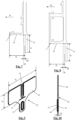
- This reference line (H) of the rear wall (11) is shown in Figs. 7 and 8 .
- This displacement ⁇ d is preferably 0 ⁇ ⁇ d ⁇ the transverse frame tolerance (d rt ).
- one or more distance pieces (22) may be fitted between the flange (8) and the window profile (21), in order to be able to compensate the dimensional tolerances of the window profile assembly (3) and for example of the screen housing in which a roll-up/roll-down screen is installed.
- This displacement ⁇ d is preferably equal to the transverse frame tolerance (d rt ) (or equal to the transverse screen tolerance (dst), since the two are equal), as is the case in the embodiments shown.
- d rt the transverse frame tolerance
- dst the transverse screen tolerance
- the displacement ⁇ d of the flange is now also 2 mm.
- the distance pieces (22) are made with a thickness (da) of 1 mm.
- the transverse screen outside dimension (d s ) is equal to the nominal transverse screen outside dimension (d sn ) and the transverse frame outside dimension (d r ) is equal to the nominal transverse screen outside dimension (d rn ). Then 2 distance pieces (22) are fitted on either side to compensate the displacement ⁇ d, so that 4 mm is compensated in total.
- the screen device can be mounted by allowing the flange (8) to abut on either side against the respective window profile of the window profile assembly (3).
- 4 distance pieces (22) this is the maximum number of distance pieces (22) as shown in Fig. 5 ) may be fitted on either side between the flanges (8) and the respective window profiles.
- the basic profiles (6) shown may for example be manufactured from aluminium with a width that is less than 30 mm and may even be about 20 mm or less.
- the distance pieces (22) shown comprise in each case a basic body (34) and an engaging element (35) projecting relative to the basic body (34).
- the basic body (34) is intended to extend in the installed state between the flange (8) and the window profile assembly (5).
- the basic body (34) then has in each case a height (h a ) that corresponds to the height (hf) of the flange (8).
- these are each provided with a slot (23) with barbs, for receiving a screw (20) for fixation of the distance piece (22) relative to the screw (20).
- the thickness (da) of the distance pieces (22) is, as in the embodiment shown, preferably selected so that said displacement ⁇ d can be compensated with a multiple thereof.
- the engaging element (35) is intended for securing the distance piece (22) and for this purpose extends in the installed state farther from the side wall (7) than the flange (8).
- This engaging element (35) is provided on one of its sides with a projecting part (38) and on its other side with a corresponding recess (39), so that distance pieces (22) fitted against each other can be aligned relative to each other by fitting a projecting part (38) of one distance piece (22) in the corresponding recess (39) of the other distance piece (22).
- the basic body (34) is of compression-resistant configuration so as to be able to transmit the necessary forces.
- the basic body (34) is also made wide enough (ba).
- the basic profile (6) is thus fastened on the window profile (21) (wherein distance pieces (22) may be fitted between the flange (8) and the window profile (21)), before this window profile (21) is installed together with the rest of the window section (5) in a wall opening in a wall (19) of a building.
- the flange (8) will extend between this wall (19) and the window profile assembly (3).
- the screen profile assembly (2) is installed in this way in a cavity of a wall (19), wherein an elastic cement (32) is applied between the screen profile assembly (2) and the brickwork (31).
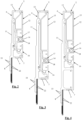
- Fig. 1 the first embodiment from Fig. 3 is installed in such a way that a screen guided with this is mounted tightly against the window section (5) in order to screen this window section (5).
- the screen profile assembly (2) from Fig. 2 is mounted against a minimalistic window profile (21) of a sash window (5), wherein a screen guided with this (not shown) is mounted tightly against this sash window (5).
- the screen profile assembly (2) from Fig. 4 is mounted against a minimalistic window profile (21) of a sash window (5), wherein a screen guided with this (not shown) is mounted far from the sash window (5), as the insert profile (15) and the securing profile (16) are reversed relative to the position from Fig. 4 .
- the basic profile (6) is in each case provided with a slot (10) for fitting this seal (9) therein.
- this slot (10) itself would be able to serve as a moisture barrier.
Landscapes
- Engineering & Computer Science (AREA)
- Structural Engineering (AREA)
- Civil Engineering (AREA)
- Architecture (AREA)
- Wing Frames And Configurations (AREA)
- Threshing Machine Elements (AREA)
Applications Claiming Priority (1)
| Application Number | Priority Date | Filing Date | Title |
|---|---|---|---|
| BE20215846A BE1029888B1 (nl) | 2021-10-29 | 2021-10-29 | Schermprofielsamenstel |
Publications (2)
| Publication Number | Publication Date |
|---|---|
| EP4174280A1 true EP4174280A1 (fr) | 2023-05-03 |
| EP4174280B1 EP4174280B1 (fr) | 2026-04-29 |
Family
ID=78401966
Family Applications (1)
| Application Number | Title | Priority Date | Filing Date |
|---|---|---|---|
| EP22202406.9A Active EP4174280B1 (fr) | 2021-10-29 | 2022-10-19 | Ensemble d'une section de fenêtre et d'un dispositif d'écran |
Country Status (2)
| Country | Link |
|---|---|
| EP (1) | EP4174280B1 (fr) |
| BE (1) | BE1029888B1 (fr) |
Citations (5)
| Publication number | Priority date | Publication date | Assignee | Title |
|---|---|---|---|---|
| DE2221988A1 (de) | 1972-05-05 | 1973-11-15 | Uhl Kg Geb | Vorrichtung zur fuehrung von rolladen oder aehnlichen verstellbaren teilen |
| DE29708747U1 (de) | 1997-05-16 | 1997-07-17 | Seitz, Eugen, 71546 Aspach | Fenster-, Türanordnung o.dgl. |
| BE1018779A5 (nl) | 2009-06-16 | 2011-08-02 | Renson Ventilation Nv | Profielbevestigingssysteem. |
| DE102016111266A9 (de) * | 2016-06-20 | 2018-02-15 | Heroal - Johann Henkenjohann Gmbh & Co. Kg | Zargenprofil und daraus gebildete Montagezarge |
| EP3271540B1 (fr) | 2016-06-06 | 2019-05-15 | Renson Sunprotection-Screens NV | Dispositif d'écran |
-
2021
- 2021-10-29 BE BE20215846A patent/BE1029888B1/nl active IP Right Grant
-
2022
- 2022-10-19 EP EP22202406.9A patent/EP4174280B1/fr active Active
Patent Citations (5)
| Publication number | Priority date | Publication date | Assignee | Title |
|---|---|---|---|---|
| DE2221988A1 (de) | 1972-05-05 | 1973-11-15 | Uhl Kg Geb | Vorrichtung zur fuehrung von rolladen oder aehnlichen verstellbaren teilen |
| DE29708747U1 (de) | 1997-05-16 | 1997-07-17 | Seitz, Eugen, 71546 Aspach | Fenster-, Türanordnung o.dgl. |
| BE1018779A5 (nl) | 2009-06-16 | 2011-08-02 | Renson Ventilation Nv | Profielbevestigingssysteem. |
| EP3271540B1 (fr) | 2016-06-06 | 2019-05-15 | Renson Sunprotection-Screens NV | Dispositif d'écran |
| DE102016111266A9 (de) * | 2016-06-20 | 2018-02-15 | Heroal - Johann Henkenjohann Gmbh & Co. Kg | Zargenprofil und daraus gebildete Montagezarge |
Non-Patent Citations (2)
| Title |
|---|
| ANONYMOUS: "Fixscreen minimal", RENSON, 1 January 2022 (2022-01-01), pages 1 - 15, XP093262571, Retrieved from the Internet <URL: https://www.kvalitetsmarkiser.dk/wp-content/uploads/2022/01/Fixscreen-Minimal-IM-7- eng.pdf> |
| RENSON: "Fixscreen Minimal - Ease of installation above all", YOUTUBE, 8 September 2022 (2022-09-08), XP093262582, Retrieved from the Internet <URL:https://www.youtube.com/watch?v=jJw9xUEaw8U> |
Also Published As
| Publication number | Publication date |
|---|---|
| BE1029888A1 (nl) | 2023-05-30 |
| EP4174280B1 (fr) | 2026-04-29 |
| BE1029888B1 (nl) | 2023-06-05 |
Similar Documents
| Publication | Publication Date | Title |
|---|---|---|
| CA2463200C (fr) | Contenant a fenetre | |
| US9970231B2 (en) | Quick release cladding system for fenestration frames | |
| US9217280B2 (en) | Screening arrangement comprising means for mounting side rails and method of mounting such a screening arrangement | |
| CA1135565A (fr) | Appareil et methode servant a remplacer des fenetres | |
| MX2014008622A (es) | Sistema de colocacion de entreventanas en campo para ventanas y puertas. | |
| US7340866B1 (en) | Wall adapter | |
| DE3720691C2 (de) | Montagezarge für Fenster oder Türen in zweischaligem Mauerwerk | |
| US20250341126A1 (en) | Apparatus and method for installing a closure in a building | |
| EP4174280A1 (fr) | Ensemble d'une section de fenêtre et d'un dispositif d'écran | |
| US20090107061A1 (en) | Reinforcement of sliding glass doors and windows | |
| ES2366128T3 (es) | Cajón de persiana enrollable montado por el exterior. | |
| US20240247535A1 (en) | Attachable blind bracket for window | |
| EP3677746B1 (fr) | Unité de profilé destinée au guidage de volet roulant et à la fixation d'au moins un élément de protection contres les chutes à un châssis dormant ou à un jambage d'une fenêtre | |
| US4432163A (en) | Adjustable mounting system for patio doors and the like | |
| GB2313857A (en) | A method of attaching solar shading to curtain walling | |
| GB2525183A (en) | Fenestration products | |
| KR20130051327A (ko) | 창호용 차수 판 | |
| GB2341410A (en) | Window mounting method | |
| DE202005000603U1 (de) | Anschlussprofil und Riegel-Pfosten-Konstruktion | |
| KR102018426B1 (ko) | 재단 및 조립이 용이한 입면 분할 창호 | |
| EP2937504A1 (fr) | Dispositif destiné à être utilisé sur un coin d'un cadre | |
| EP3578748A1 (fr) | Châssis de porte ou de fenêtre à guidage de store pour façades | |
| CN223075396U (zh) | 一种边框中框通用的窄边门窗 | |
| JP7815016B2 (ja) | シャッター装置及びシャッター装置の施工方法 | |
| EP2933419B1 (fr) | Produits de fenêtrage |
Legal Events
| Date | Code | Title | Description |
|---|---|---|---|
| PUAI | Public reference made under article 153(3) epc to a published international application that has entered the european phase |
Free format text: ORIGINAL CODE: 0009012 |
|
| STAA | Information on the status of an ep patent application or granted ep patent |
Free format text: STATUS: THE APPLICATION HAS BEEN PUBLISHED |
|
| AK | Designated contracting states |
Kind code of ref document: A1 Designated state(s): AL AT BE BG CH CY CZ DE DK EE ES FI FR GB GR HR HU IE IS IT LI LT LU LV MC ME MK MT NL NO PL PT RO RS SE SI SK SM TR |
|
| STAA | Information on the status of an ep patent application or granted ep patent |
Free format text: STATUS: REQUEST FOR EXAMINATION WAS MADE |
|
| 17P | Request for examination filed |
Effective date: 20231025 |
|
| RAP3 | Party data changed (applicant data changed or rights of an application transferred) |
Owner name: RENSON SUNPROTECTION SCREENS |
|
| RBV | Designated contracting states (corrected) |
Designated state(s): AL AT BE BG CH CY CZ DE DK EE ES FI FR GB GR HR HU IE IS IT LI LT LU LV MC ME MK MT NL NO PL PT RO RS SE SI SK SM TR |
|
| RAP1 | Party data changed (applicant data changed or rights of an application transferred) |
Owner name: RENSON NV |
|
| TPAC | Observations filed by third parties |
Free format text: ORIGINAL CODE: EPIDOSNTIPA |
|
| STAA | Information on the status of an ep patent application or granted ep patent |
Free format text: STATUS: EXAMINATION IS IN PROGRESS |
|
| 17Q | First examination report despatched |
Effective date: 20250718 |
|
| TPAC | Observations filed by third parties |
Free format text: ORIGINAL CODE: EPIDOSNTIPA |
|
| GRAP | Despatch of communication of intention to grant a patent |
Free format text: ORIGINAL CODE: EPIDOSNIGR1 |
|
| STAA | Information on the status of an ep patent application or granted ep patent |
Free format text: STATUS: GRANT OF PATENT IS INTENDED |
|
| RIC1 | Information provided on ipc code assigned before grant |
Ipc: E06B 9/58 20060101AFI20260203BHEP Ipc: E06B 1/68 20060101ALI20260203BHEP Ipc: E06B 3/263 20060101ALN20260203BHEP Ipc: E06B 1/64 20060101ALN20260203BHEP Ipc: E06B 3/26 20060101ALN20260203BHEP |
|
| GRAS | Grant fee paid |
Free format text: ORIGINAL CODE: EPIDOSNIGR3 |
|
| INTG | Intention to grant announced |
Effective date: 20260219 |
|
| GRAA | (expected) grant |
Free format text: ORIGINAL CODE: 0009210 |
|
| STAA | Information on the status of an ep patent application or granted ep patent |
Free format text: STATUS: THE PATENT HAS BEEN GRANTED |
|
| AK | Designated contracting states |
Kind code of ref document: B1 Designated state(s): AL AT BE BG CH CY CZ DE DK EE ES FI FR GB GR HR HU IE IS IT LI LT LU LV MC ME MK MT NL NO PL PT RO RS SE SI SK SM TR |
|
| REG | Reference to a national code |
Ref country code: CH Ref legal event code: F10 Free format text: ST27 STATUS EVENT CODE: U-0-0-F10-F00 (AS PROVIDED BY THE NATIONAL OFFICE) Effective date: 20260429 |