EP4174283A1 - Machine de construction et procédé de fonctionnement de la machine de construction - Google Patents
Machine de construction et procédé de fonctionnement de la machine de construction Download PDFInfo
- Publication number
- EP4174283A1 EP4174283A1 EP21205518.0A EP21205518A EP4174283A1 EP 4174283 A1 EP4174283 A1 EP 4174283A1 EP 21205518 A EP21205518 A EP 21205518A EP 4174283 A1 EP4174283 A1 EP 4174283A1
- Authority
- EP
- European Patent Office
- Prior art keywords
- feed
- force
- construction machine
- working carriage
- main
- Prior art date
- Legal status (The legal status is an assumption and is not a legal conclusion. Google has not performed a legal analysis and makes no representation as to the accuracy of the status listed.)
- Granted
Links
Images
Classifications
-
- E—FIXED CONSTRUCTIONS
- E21—EARTH OR ROCK DRILLING; MINING
- E21B—EARTH OR ROCK DRILLING; OBTAINING OIL, GAS, WATER, SOLUBLE OR MELTABLE MATERIALS OR A SLURRY OF MINERALS FROM WELLS
- E21B7/00—Special methods or apparatus for drilling
- E21B7/02—Drilling rigs characterised by means for land transport with their own drive, e.g. skid mounting or wheel mounting
-
- E—FIXED CONSTRUCTIONS
- E21—EARTH OR ROCK DRILLING; MINING
- E21B—EARTH OR ROCK DRILLING; OBTAINING OIL, GAS, WATER, SOLUBLE OR MELTABLE MATERIALS OR A SLURRY OF MINERALS FROM WELLS
- E21B44/00—Automatic control systems specially adapted for drilling operations, i.e. self-operating systems which function to carry out or modify a drilling operation without intervention of a human operator, e.g. computer-controlled drilling systems; Systems specially adapted for monitoring a plurality of drilling variables or conditions
- E21B44/02—Automatic control of the tool feed
-
- E—FIXED CONSTRUCTIONS
- E21—EARTH OR ROCK DRILLING; MINING
- E21B—EARTH OR ROCK DRILLING; OBTAINING OIL, GAS, WATER, SOLUBLE OR MELTABLE MATERIALS OR A SLURRY OF MINERALS FROM WELLS
- E21B19/00—Handling rods, casings, tubes or the like outside the borehole, e.g. in the derrick; Apparatus for feeding the rods or cables
- E21B19/008—Winding units, specially adapted for drilling operations
-
- E—FIXED CONSTRUCTIONS
- E21—EARTH OR ROCK DRILLING; MINING
- E21B—EARTH OR ROCK DRILLING; OBTAINING OIL, GAS, WATER, SOLUBLE OR MELTABLE MATERIALS OR A SLURRY OF MINERALS FROM WELLS
- E21B19/00—Handling rods, casings, tubes or the like outside the borehole, e.g. in the derrick; Apparatus for feeding the rods or cables
- E21B19/08—Apparatus for feeding the rods or cables; Apparatus for increasing or decreasing the pressure on the drilling tool; Apparatus for counterbalancing the weight of the rods
- E21B19/084—Apparatus for feeding the rods or cables; Apparatus for increasing or decreasing the pressure on the drilling tool; Apparatus for counterbalancing the weight of the rods with flexible drawing means, e.g. cables
-
- E—FIXED CONSTRUCTIONS
- E21—EARTH OR ROCK DRILLING; MINING
- E21B—EARTH OR ROCK DRILLING; OBTAINING OIL, GAS, WATER, SOLUBLE OR MELTABLE MATERIALS OR A SLURRY OF MINERALS FROM WELLS
- E21B44/00—Automatic control systems specially adapted for drilling operations, i.e. self-operating systems which function to carry out or modify a drilling operation without intervention of a human operator, e.g. computer-controlled drilling systems; Systems specially adapted for monitoring a plurality of drilling variables or conditions
-
- E—FIXED CONSTRUCTIONS
- E21—EARTH OR ROCK DRILLING; MINING
- E21B—EARTH OR ROCK DRILLING; OBTAINING OIL, GAS, WATER, SOLUBLE OR MELTABLE MATERIALS OR A SLURRY OF MINERALS FROM WELLS
- E21B7/00—Special methods or apparatus for drilling
- E21B7/02—Drilling rigs characterised by means for land transport with their own drive, e.g. skid mounting or wheel mounting
- E21B7/022—Control of the drilling operation; Hydraulic or pneumatic means for activation or operation
Definitions
- the invention relates to a construction machine, in particular a drilling device with a mobile carrier device, a leader arranged thereon with a linear guide and a working carriage which is mounted on the linear guide of the leader so that it can move vertically and is designed to hold a processing tool, according to claim 1.
- the invention also relates to a method for operating such a construction machine according to claim 9.
- a construction machine for drilling is, for example, from EP 2 378 053 A1 known.
- a drill drive for rotating a drilling tool with an auger is provided on the working carriage.
- the drilling tool has a drilling rod, a so-called Kelly rod, which is suspended from a main cable of a main winch. The weight of the drill pipe including the drilling tool is held and absorbed by the main cable.
- the drill string is passed through the ring-shaped drill drive, a so-called top drive, with a torque being able to be transmitted from a ring-shaped drive wheel to outer driver strips of the drill string.
- the drilling tool such as an endless screw
- the so-called top drive the drilling drive
- the feed cable is attached to the drilling drive.
- the working carriage with the drilling drive can be moved down along the leader via a feed unit.
- the invention is based on the object of specifying a construction machine and a method with which particularly safe operation of the construction machine can be achieved.
- the object is achieved by a construction machine having the features of claim 1 or by a method having the features of claim 9 .
- Preferred embodiments are given in the dependent claims.
- a first aspect of the invention is that the main rope of the main winch is connected to the working carriage, so that the main winch can act directly on the working carriage.
- the main cable can be attached directly to the working carriage or indirectly, with a deflection pulley being mounted on the working carriage.
- the main rope can be guided like a pulley block around the pulley and mast be attached.
- the main winch can absorb and compensate the weight of the processing tool connected to the working carriage as well as the working carriage.
- the working carriage can be moved by a feed unit that is separate from the main winch, with the feed unit applying a feed force downwards or upwards to the working carriage and thus to the machining tool, as required.
- a first measuring device is provided, with which the current actual feed force, which is exerted on the implement carriage, is recorded.
- the current actual feed force value is transmitted from the measuring device to a control device in which an upper limit value and/or a lower limit value for the feed force are stored for the feed unit. If the actual feed force value exceeds or falls below one of the stored limit values, the main winch is selectively actuated according to a predetermined control program by the control device to protect the feed unit and ensure the operational reliability of the entire machine.
- the control is designed in such a way that the current actual feed force value remains within the range between the limit values due to the additional effect of the main winch, or in any case falls below the upper limit value again or exceeds the lower limit value again.
- the main winch is activated by the control device in such a way that an additional upward pulling force is exerted on the working device carriage via the main cable. This prevents the drilling tool from being screwed into the ground, so that the drilling tool continues to remove ground material during a defined, predetermined feed movement.
- the preset holding force on the main winch can be reduced via the control unit to compensate for weight, so that part or almost the entire weight of the working device carriage with the processing tool additionally down in feed direction works. Only a certain residual tensile force is retained on the main rope to prevent slack rope.
- control device is designed in such a way that it automatically carries out the measurement and control processes that can lead to regulation. As a result, a machine operator is considerably relieved when operating the construction machine, and dangerous operating situations of the construction machine can be reliably avoided.
- a preferred embodiment of the construction machine according to the invention consists in that a second measuring device is provided for detecting a cable force in the main cable and that the control device is designed to control the main winch and the feed unit so that a minimum cable force is given in the main cable.
- the feed unit can be designed in any suitable way. According to a development of the invention, it is particularly preferred that the feed unit has a linear drive, in particular an actuating cylinder.
- the actuating cylinder can in particular be designed as a hydraulic cylinder.
- the feed unit can have a double-acting cylinder, through which a feed force can be effected both downwards and upwards. Two single-acting actuating cylinders can also be provided in the opposite arrangement.
- the at least one actuating cylinder can be used directly or via feed cables be connected to the working carriage. It is also possible for an actuating cylinder to also be used to set a pretension on a feed cable.
- the feed unit it is advantageous for the feed unit to have a feed winch.
- the feed winch can include a winch that can be driven in both directions of rotation. In this way, tensile forces can be applied in both directions, i.e. upwards or downwards.
- the feed unit has an upper feed rope for exerting an upward feed force and a lower feed rope for exerting a downward feed force on the working carriage.
- a feed winch in particular, two feed ropes can be wound on the winch drum in such a way that the upper feed rope winds up when the lower feed rope unwinds, and vice versa.
- the carriage can be moved up or down along the leader.
- Sufficient cable tension can be achieved by means of one or more adjusting cylinders, for example by means of a tension pulley.
- the feed cables can be guided over deflection pulleys.
- the measuring devices can be designed in any suitable manner for detecting the desired forces.
- a force measurement can be made at the end of the rope or at the winch.
- the construction machine can be designed in any way, in particular as a civil engineering machine for carrying out a soil-working civil engineering measure.
- a vibrator or a ram for inserting or pulling sheet piles in the ground can be provided on the implement carriage.
- the construction machine is designed as a drilling device and that a drilling drive for rotating a drilling tool is mounted on the working carriage is arranged.
- Such drills can be used in particular to create foundation piles in the ground.
- the drilling tool has an auger.
- Particularly safe operation can be achieved in this embodiment of a drilling device in particular, since a potentially dangerous operating situation due to a so-called corkscrew effect can be reliably avoided by screwing the auger into the ground.
- the construction machine described above can be operated according to a method which is characterized in that the first measuring device detects an actual feed force which is exerted on the working carriage by the feed unit and that the main winch is controlled by the control device depending on a currently detected actual feed force value is controlled automatically, so that the detected actual feed force value falls below the upper limit or exceeds the lower limit.
- the advantages described above can be achieved by the method according to the invention when operating a construction machine according to the invention.
- the actual feed force value can be kept in the set range between the upper limit value and the lower limit value.
- efficient and safer operation of the construction machine can be achieved.
- a preferred variant of the method according to the invention is that a cable force in the main cable is detected with a second measuring device and that the main winch and the feed unit are controlled by the control device so that a minimum cable force in the main cable is set.
- the control device can thus ensure sufficient cable tension in the main cable, which reliably counteracts the occurrence of slack cable.
- a drilling drive is arranged on the working carriage, with which a drilling tool with a drilling auger is driven in rotation, and that a borehole is created in the ground with the drilling tool.
- a drilling drive is arranged on the working carriage, with which a drilling tool with a drilling auger is driven in rotation, and that a borehole is created in the ground with the drilling tool.
- the borehole in the ground can be used in particular to create a foundation element.
- the borehole can be filled with a hardenable suspension to form the foundation element.
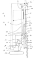
- a construction machine 10 which is designed as a drilling device 12 with a carrier device 14 .
- the mobile carrier device 14 has an undercarriage 16 with a crawler chassis.
- An upper carriage 18 is rotatably mounted on the undercarriage 16 about a vertical axis.
- a substantially vertically directed mast-like leader 20 with a linear guide 22 is adjustably mounted on its front side on the superstructure 18 via a linkage mechanism 19 .
- a working carriage 30 with a drill drive 32 for driving a machining tool 40 in rotation is provided along the linear guide 22 .
- the processing tool 40 is designed as a drilling tool 42 with a drilling auger 44 .
- the working carriage 30 is held on a main cable 52 of a main winch 50 .
- the main cable 52 is from the main winch 50, which can be arranged on a rear side of the leader 20 or at another position on the superstructure 18, via a mast head 24 at the upper end of the leader 20 with two mast deflection rollers 56a, 56b to a Fastening element 34 out, with which the main cable 52 is connected to the working carriage 30.
- the main winch 50 is basically controlled by a control device 70 in the carrier device 14 in such a way that the weight of the working carriage 30 with the drilling drive 32 and the processing tool 40 is largely absorbed by a tensile force of the main winch 50 .
- the pulling force of the main winch 50 is set in such a way that there is a minimum tension in the main rope 52 in order to avoid slack rope.
- a feed unit 60 is provided, which in the illustrated embodiment is a feed winch 62 with an upper feed rope 64 and a lower feed rope 66 has.
- the upper feed cable 64 is guided upwards by the feed winch 62 to a first deflection pulley 68, from which the upper feed cable 64 is guided downwards again and is articulated on the working carriage 30 via a pulley (not shown).
- a free end of the upper feed cable 64 can be guided back up over the roller (not shown) on the working carriage 30 and via a further deflection to a tensioning cylinder 67, through which sufficient cable tension of the upper feed cable 64 is ensured.
- a feed force can thus be exerted upwards on the working carriage 30 and thus on the processing tool 40 via the upper feed cable 64 .
- the lower feed cable 66 is guided over two rollers 69a, 69b from below to the working carriage 30 and is fastened there or, alternatively, is guided over a deflection roller and fastened to the leader 20.
- the upper haul rope 64 and the lower haul rope 66 are arranged on the winch drum of the haul winch 62 with opposite winding.
- a feed force of the feed unit 60 can be recorded, for example, via a first measuring device 71 on the first deflection roller 68 or with a further measuring device in the area of the clamping cylinder 67 and forwarded to the control device 70 .
- a force on the main cable 52 can be detected via a second measuring device 72, which is arranged in the illustrated exemplary embodiment in the region of the first mast deflection roller 56a on the mast head 24.
- the second measuring device 72 is also connected to the control device 70 .
- An upper limit value and a lower limit value for the feed force can be stored in the control device 70 for the feed unit 60 .
- the control device 70 is designed in such a way that the main winch 50 is automatically controlled as a function of an actual feed force value that is recorded by the first measuring device 71, with the recorded actual feed force value being controlled or regulated in such a way that it is below the upper limit value or above the lower limit.
- the control device 70 can activate the main winch 50 for support, so that the main cable 52 an additional tensile force is exerted on the working carriage 30.
- the main winch 50 can be activated by the control device 70 in such a way that the tensile force basically acting on the working carriage 30 is reduced by the main cable 52 .
- an additional downward force is exerted on the working carriage by the weight of the working carriage 30, the drilling drive 32 and the machining tool 40, whereby the downward feed force is increased and the feed unit 60 is relieved.
- This automatic activation of the main winch 50 can prevent an undesired corkscrew-like turning of the auger 44 into a soft soil layer, particularly when drilling with an auger 44, since this could cause the feed unit 60 to be overloaded and the drill 12 to tilt.
- the control device 70 according to the invention thus also contributes to increasing operational reliability.
Landscapes
- Engineering & Computer Science (AREA)
- Life Sciences & Earth Sciences (AREA)
- Geology (AREA)
- Mining & Mineral Resources (AREA)
- Physics & Mathematics (AREA)
- Environmental & Geological Engineering (AREA)
- Fluid Mechanics (AREA)
- General Life Sciences & Earth Sciences (AREA)
- Geochemistry & Mineralogy (AREA)
- Mechanical Engineering (AREA)
- Earth Drilling (AREA)
Priority Applications (2)
| Application Number | Priority Date | Filing Date | Title |
|---|---|---|---|
| EP21205518.0A EP4174283B1 (fr) | 2021-10-29 | 2021-10-29 | Machine de construction et procédé de fonctionnement de la machine de construction |
| CN202211069203.7A CN116065951B (zh) | 2021-10-29 | 2022-09-02 | 工程机械和用于运行工程机械的方法 |
Applications Claiming Priority (1)
| Application Number | Priority Date | Filing Date | Title |
|---|---|---|---|
| EP21205518.0A EP4174283B1 (fr) | 2021-10-29 | 2021-10-29 | Machine de construction et procédé de fonctionnement de la machine de construction |
Publications (3)
| Publication Number | Publication Date |
|---|---|
| EP4174283A1 true EP4174283A1 (fr) | 2023-05-03 |
| EP4174283C0 EP4174283C0 (fr) | 2023-12-06 |
| EP4174283B1 EP4174283B1 (fr) | 2023-12-06 |
Family
ID=78414488
Family Applications (1)
| Application Number | Title | Priority Date | Filing Date |
|---|---|---|---|
| EP21205518.0A Active EP4174283B1 (fr) | 2021-10-29 | 2021-10-29 | Machine de construction et procédé de fonctionnement de la machine de construction |
Country Status (2)
| Country | Link |
|---|---|
| EP (1) | EP4174283B1 (fr) |
| CN (1) | CN116065951B (fr) |
Citations (6)
| Publication number | Priority date | Publication date | Assignee | Title |
|---|---|---|---|---|
| US4150727A (en) * | 1978-01-11 | 1979-04-24 | Hughes Tool Company | Downcrowding device for earth boring machines |
| EP2378053A1 (fr) | 2010-04-16 | 2011-10-19 | BAUER Maschinen GmbH | Engin doté d'une unité de calcul pour déterminer une zone de réglage |
| EP2767672A2 (fr) * | 2013-02-19 | 2014-08-20 | PRAKLA Bohrtechnik GmbH | Dispositif de réalisation d'un forage dans le sol |
| EP2975208A2 (fr) * | 2014-07-15 | 2016-01-20 | BAUER Maschinen GmbH | Engin et procédé de commande d'un engin |
| US20170284162A1 (en) * | 2016-04-04 | 2017-10-05 | Bauer Maschinen Gmbh | Machine and method for earth-working |
| US20180313165A1 (en) * | 2017-03-03 | 2018-11-01 | Pro-Dig Gi, Llc | Masted drill rig with system for applying push and/or pull force to a tool |
Family Cites Families (2)
| Publication number | Priority date | Publication date | Assignee | Title |
|---|---|---|---|---|
| GB1504861A (en) * | 1974-03-25 | 1978-03-22 | Rock Fall Co Ltd | Drilling machine constant feed-force apparatus |
| CN110924925A (zh) * | 2019-11-28 | 2020-03-27 | 徐州徐工基础工程机械有限公司 | 基于工况模式的旋挖钻机提升力控制及监测系统、方法 |
-
2021
- 2021-10-29 EP EP21205518.0A patent/EP4174283B1/fr active Active
-
2022
- 2022-09-02 CN CN202211069203.7A patent/CN116065951B/zh active Active
Patent Citations (6)
| Publication number | Priority date | Publication date | Assignee | Title |
|---|---|---|---|---|
| US4150727A (en) * | 1978-01-11 | 1979-04-24 | Hughes Tool Company | Downcrowding device for earth boring machines |
| EP2378053A1 (fr) | 2010-04-16 | 2011-10-19 | BAUER Maschinen GmbH | Engin doté d'une unité de calcul pour déterminer une zone de réglage |
| EP2767672A2 (fr) * | 2013-02-19 | 2014-08-20 | PRAKLA Bohrtechnik GmbH | Dispositif de réalisation d'un forage dans le sol |
| EP2975208A2 (fr) * | 2014-07-15 | 2016-01-20 | BAUER Maschinen GmbH | Engin et procédé de commande d'un engin |
| US20170284162A1 (en) * | 2016-04-04 | 2017-10-05 | Bauer Maschinen Gmbh | Machine and method for earth-working |
| US20180313165A1 (en) * | 2017-03-03 | 2018-11-01 | Pro-Dig Gi, Llc | Masted drill rig with system for applying push and/or pull force to a tool |
Also Published As
| Publication number | Publication date |
|---|---|
| EP4174283C0 (fr) | 2023-12-06 |
| CN116065951A (zh) | 2023-05-05 |
| EP4174283B1 (fr) | 2023-12-06 |
| CN116065951B (zh) | 2026-04-03 |
Similar Documents
| Publication | Publication Date | Title |
|---|---|---|
| EP2975208B1 (fr) | Engin et procédé de commande d'un engin | |
| EP2762438B1 (fr) | Procédé destiné à influencer la force d'entraînement d'un treuil de manoeuvre et dispositif permettant de mettre en oeuvre un tel procédé | |
| EP2322724B1 (fr) | Installation de forage d'eau souterraine et procédé d'entrée d'un élément de fondation cylindrique au fond de l'eau | |
| EP3708528B1 (fr) | Machine de travail et procédé de fonctionnement de la machine de travail | |
| EP4134489A1 (fr) | Dispositif préhenseur et procédé de fonctionnement d'un dispositif préhenseur | |
| DE1298472B (de) | Einrichtung zum Ziehen und Nachlassen des Bohrgestaenges in Bohrtuermen oder Bohrinseln | |
| EP3045416A1 (fr) | Dispositif de levage, d'abaissement ou de retenue d'une charge et procede de commande d'un tel dispositif | |
| EP1247778B1 (fr) | Treuil | |
| EP3919684B1 (fr) | Excavateur et procédé de création d'une fente dans le sol | |
| EP3613903A1 (fr) | Procédé de surveillance des charges structurelles d'une machine support pourvue d'appareil de forage et de battage ainsi que machine de travail pourvue d'appareil de battage et de forage | |
| DE102022132028B3 (de) | Kran mit Abspannbock und Verfahren zum Abspannen eines solchen | |
| DE2820325A1 (de) | Bohrlafette fuer eine gesteinsbohrmaschine | |
| EP2736831B1 (fr) | Dispositif de levage | |
| EP4174283B1 (fr) | Machine de construction et procédé de fonctionnement de la machine de construction | |
| DE102020117578B4 (de) | Verfahren sowie vorspannvorrichtung für hubseiltrommeln | |
| DE2044499C3 (de) | Anordnung zur Abstützung eines mit einem Unterwasserbohrlochkopf verbundenen Rohrleitungsstrangs und Verfahren zu deren Aufbau | |
| EP3404197B1 (fr) | Dispositif de forage et procédé de vissage d'éléments de tiges de forage comprenant un dispositif de forage | |
| DE102020113081B4 (de) | Greifvorrichtung mit Schließantrieb durch übersetzte Kraftvervielfältigung | |
| EP4215717B1 (fr) | Machine de construction et procédé de fonctionnement d'une machine de construction | |
| DE10113561B4 (de) | Vorschubvorrichtung für eine Ramm- und/oder Bohrvorrichtung | |
| EP3539917B1 (fr) | Machine de transport à tambour | |
| DE19962298C2 (de) | Einpressvorrichtung für Rohre und Bohrgestänge | |
| DE102024125138A1 (de) | Arbeitsgerät mit einem Greifer, insbesondere Schlitzwandgreifer | |
| EP2505543B1 (fr) | Appareil de construction | |
| EP1975113B1 (fr) | Dispositif de câble de commande destiné à l'utilisation lors de la pose ou du renouvellement de conduites dans le sol |
Legal Events
| Date | Code | Title | Description |
|---|---|---|---|
| PUAI | Public reference made under article 153(3) epc to a published international application that has entered the european phase |
Free format text: ORIGINAL CODE: 0009012 |
|
| STAA | Information on the status of an ep patent application or granted ep patent |
Free format text: STATUS: THE APPLICATION HAS BEEN PUBLISHED |
|
| STAA | Information on the status of an ep patent application or granted ep patent |
Free format text: STATUS: REQUEST FOR EXAMINATION WAS MADE |
|
| AK | Designated contracting states |
Kind code of ref document: A1 Designated state(s): AL AT BE BG CH CY CZ DE DK EE ES FI FR GB GR HR HU IE IS IT LI LT LU LV MC MK MT NL NO PL PT RO RS SE SI SK SM TR |
|
| 17P | Request for examination filed |
Effective date: 20230411 |
|
| RBV | Designated contracting states (corrected) |
Designated state(s): AL AT BE BG CH CY CZ DE DK EE ES FI FR GB GR HR HU IE IS IT LI LT LU LV MC MK MT NL NO PL PT RO RS SE SI SK SM TR |
|
| GRAP | Despatch of communication of intention to grant a patent |
Free format text: ORIGINAL CODE: EPIDOSNIGR1 |
|
| RIC1 | Information provided on ipc code assigned before grant |
Ipc: E21B 7/02 20060101ALI20230526BHEP Ipc: E21B 19/084 20060101ALI20230526BHEP Ipc: E21B 44/02 20060101AFI20230526BHEP |
|
| STAA | Information on the status of an ep patent application or granted ep patent |
Free format text: STATUS: GRANT OF PATENT IS INTENDED |
|
| INTG | Intention to grant announced |
Effective date: 20230706 |
|
| GRAS | Grant fee paid |
Free format text: ORIGINAL CODE: EPIDOSNIGR3 |
|
| GRAA | (expected) grant |
Free format text: ORIGINAL CODE: 0009210 |
|
| STAA | Information on the status of an ep patent application or granted ep patent |
Free format text: STATUS: THE PATENT HAS BEEN GRANTED |
|
| AK | Designated contracting states |
Kind code of ref document: B1 Designated state(s): AL AT BE BG CH CY CZ DE DK EE ES FI FR GB GR HR HU IE IS IT LI LT LU LV MC MK MT NL NO PL PT RO RS SE SI SK SM TR |
|
| REG | Reference to a national code |
Ref country code: GB Ref legal event code: FG4D Free format text: NOT ENGLISH |
|
| REG | Reference to a national code |
Ref country code: CH Ref legal event code: EP |
|
| REG | Reference to a national code |
Ref country code: DE Ref legal event code: R096 Ref document number: 502021002119 Country of ref document: DE |
|
| REG | Reference to a national code |
Ref country code: IE Ref legal event code: FG4D Free format text: LANGUAGE OF EP DOCUMENT: GERMAN |
|
| U01 | Request for unitary effect filed |
Effective date: 20231212 |
|
| U07 | Unitary effect registered |
Designated state(s): AT BE BG DE DK EE FI FR IT LT LU LV MT NL PT SE SI Effective date: 20231219 |
|
| PG25 | Lapsed in a contracting state [announced via postgrant information from national office to epo] |
Ref country code: GR Free format text: LAPSE BECAUSE OF FAILURE TO SUBMIT A TRANSLATION OF THE DESCRIPTION OR TO PAY THE FEE WITHIN THE PRESCRIBED TIME-LIMIT Effective date: 20240307 |
|
| PG25 | Lapsed in a contracting state [announced via postgrant information from national office to epo] |
Ref country code: ES Free format text: LAPSE BECAUSE OF FAILURE TO SUBMIT A TRANSLATION OF THE DESCRIPTION OR TO PAY THE FEE WITHIN THE PRESCRIBED TIME-LIMIT Effective date: 20231206 |
|
| PG25 | Lapsed in a contracting state [announced via postgrant information from national office to epo] |
Ref country code: GR Free format text: LAPSE BECAUSE OF FAILURE TO SUBMIT A TRANSLATION OF THE DESCRIPTION OR TO PAY THE FEE WITHIN THE PRESCRIBED TIME-LIMIT Effective date: 20240307 Ref country code: ES Free format text: LAPSE BECAUSE OF FAILURE TO SUBMIT A TRANSLATION OF THE DESCRIPTION OR TO PAY THE FEE WITHIN THE PRESCRIBED TIME-LIMIT Effective date: 20231206 |
|
| PG25 | Lapsed in a contracting state [announced via postgrant information from national office to epo] |
Ref country code: RS Free format text: LAPSE BECAUSE OF FAILURE TO SUBMIT A TRANSLATION OF THE DESCRIPTION OR TO PAY THE FEE WITHIN THE PRESCRIBED TIME-LIMIT Effective date: 20231206 Ref country code: NO Free format text: LAPSE BECAUSE OF FAILURE TO SUBMIT A TRANSLATION OF THE DESCRIPTION OR TO PAY THE FEE WITHIN THE PRESCRIBED TIME-LIMIT Effective date: 20240306 Ref country code: HR Free format text: LAPSE BECAUSE OF FAILURE TO SUBMIT A TRANSLATION OF THE DESCRIPTION OR TO PAY THE FEE WITHIN THE PRESCRIBED TIME-LIMIT Effective date: 20231206 |
|
| PG25 | Lapsed in a contracting state [announced via postgrant information from national office to epo] |
Ref country code: IS Free format text: LAPSE BECAUSE OF FAILURE TO SUBMIT A TRANSLATION OF THE DESCRIPTION OR TO PAY THE FEE WITHIN THE PRESCRIBED TIME-LIMIT Effective date: 20240406 |
|
| PG25 | Lapsed in a contracting state [announced via postgrant information from national office to epo] |
Ref country code: CZ Free format text: LAPSE BECAUSE OF FAILURE TO SUBMIT A TRANSLATION OF THE DESCRIPTION OR TO PAY THE FEE WITHIN THE PRESCRIBED TIME-LIMIT Effective date: 20231206 |
|
| PG25 | Lapsed in a contracting state [announced via postgrant information from national office to epo] |
Ref country code: SK Free format text: LAPSE BECAUSE OF FAILURE TO SUBMIT A TRANSLATION OF THE DESCRIPTION OR TO PAY THE FEE WITHIN THE PRESCRIBED TIME-LIMIT Effective date: 20231206 |
|
| PG25 | Lapsed in a contracting state [announced via postgrant information from national office to epo] |
Ref country code: SM Free format text: LAPSE BECAUSE OF FAILURE TO SUBMIT A TRANSLATION OF THE DESCRIPTION OR TO PAY THE FEE WITHIN THE PRESCRIBED TIME-LIMIT Effective date: 20231206 Ref country code: SK Free format text: LAPSE BECAUSE OF FAILURE TO SUBMIT A TRANSLATION OF THE DESCRIPTION OR TO PAY THE FEE WITHIN THE PRESCRIBED TIME-LIMIT Effective date: 20231206 Ref country code: RO Free format text: LAPSE BECAUSE OF FAILURE TO SUBMIT A TRANSLATION OF THE DESCRIPTION OR TO PAY THE FEE WITHIN THE PRESCRIBED TIME-LIMIT Effective date: 20231206 Ref country code: IS Free format text: LAPSE BECAUSE OF FAILURE TO SUBMIT A TRANSLATION OF THE DESCRIPTION OR TO PAY THE FEE WITHIN THE PRESCRIBED TIME-LIMIT Effective date: 20240406 Ref country code: CZ Free format text: LAPSE BECAUSE OF FAILURE TO SUBMIT A TRANSLATION OF THE DESCRIPTION OR TO PAY THE FEE WITHIN THE PRESCRIBED TIME-LIMIT Effective date: 20231206 |
|
| PG25 | Lapsed in a contracting state [announced via postgrant information from national office to epo] |
Ref country code: PL Free format text: LAPSE BECAUSE OF FAILURE TO SUBMIT A TRANSLATION OF THE DESCRIPTION OR TO PAY THE FEE WITHIN THE PRESCRIBED TIME-LIMIT Effective date: 20231206 |
|
| PG25 | Lapsed in a contracting state [announced via postgrant information from national office to epo] |
Ref country code: PL Free format text: LAPSE BECAUSE OF FAILURE TO SUBMIT A TRANSLATION OF THE DESCRIPTION OR TO PAY THE FEE WITHIN THE PRESCRIBED TIME-LIMIT Effective date: 20231206 |
|
| REG | Reference to a national code |
Ref country code: DE Ref legal event code: R026 Ref document number: 502021002119 Country of ref document: DE |
|
| PLBI | Opposition filed |
Free format text: ORIGINAL CODE: 0009260 |
|
| PLAB | Opposition data, opponent's data or that of the opponent's representative modified |
Free format text: ORIGINAL CODE: 0009299OPPO |
|
| PLAX | Notice of opposition and request to file observation + time limit sent |
Free format text: ORIGINAL CODE: EPIDOSNOBS2 |
|
| 26 | Opposition filed |
Opponent name: LIEBHERR-WERK NENZING GMBH Effective date: 20240903 |
|
| R26 | Opposition filed (corrected) |
Opponent name: LIEBHERR-WERK NENZING GMBH Effective date: 20240903 |
|
| U20 | Renewal fee for the european patent with unitary effect paid |
Year of fee payment: 4 Effective date: 20241028 |
|
| PLAP | Information related to despatch of examination report in opposition + time limit deleted |
Free format text: ORIGINAL CODE: EPIDOSDORE2 |
|
| PLAT | Information related to reply to examination report in opposition deleted |
Free format text: ORIGINAL CODE: EPIDOSDORE3 |
|
| PLAY | Examination report in opposition despatched + time limit |
Free format text: ORIGINAL CODE: EPIDOSNORE2 |
|
| PLBB | Reply of patent proprietor to notice(s) of opposition received |
Free format text: ORIGINAL CODE: EPIDOSNOBS3 |
|
| PLBC | Reply to examination report in opposition received |
Free format text: ORIGINAL CODE: EPIDOSNORE3 |
|
| REG | Reference to a national code |
Ref country code: CH Ref legal event code: PL |
|
| PG25 | Lapsed in a contracting state [announced via postgrant information from national office to epo] |
Ref country code: MC Free format text: LAPSE BECAUSE OF FAILURE TO SUBMIT A TRANSLATION OF THE DESCRIPTION OR TO PAY THE FEE WITHIN THE PRESCRIBED TIME-LIMIT Effective date: 20231206 |
|
| PG25 | Lapsed in a contracting state [announced via postgrant information from national office to epo] |
Ref country code: CH Free format text: LAPSE BECAUSE OF NON-PAYMENT OF DUE FEES Effective date: 20241031 |
|
| PG25 | Lapsed in a contracting state [announced via postgrant information from national office to epo] |
Ref country code: IE Free format text: LAPSE BECAUSE OF NON-PAYMENT OF DUE FEES Effective date: 20241029 |
|
| PLAB | Opposition data, opponent's data or that of the opponent's representative modified |
Free format text: ORIGINAL CODE: 0009299OPPO |
|
| R26 | Opposition filed (corrected) |
Opponent name: LIEBHERR-WERK NENZING GMBH Effective date: 20240903 |
|
| U20 | Renewal fee for the european patent with unitary effect paid |
Year of fee payment: 5 Effective date: 20251030 |
|
| PG25 | Lapsed in a contracting state [announced via postgrant information from national office to epo] |
Ref country code: HU Free format text: LAPSE BECAUSE OF FAILURE TO SUBMIT A TRANSLATION OF THE DESCRIPTION OR TO PAY THE FEE WITHIN THE PRESCRIBED TIME-LIMIT; INVALID AB INITIO Effective date: 20211029 |
|
| PG25 | Lapsed in a contracting state [announced via postgrant information from national office to epo] |
Ref country code: CY Free format text: LAPSE BECAUSE OF FAILURE TO SUBMIT A TRANSLATION OF THE DESCRIPTION OR TO PAY THE FEE WITHIN THE PRESCRIBED TIME-LIMIT; INVALID AB INITIO Effective date: 20211029 |