EP4174333B1 - Ensemble palier - Google Patents
Ensemble palier Download PDFInfo
- Publication number
- EP4174333B1 EP4174333B1 EP21205104.9A EP21205104A EP4174333B1 EP 4174333 B1 EP4174333 B1 EP 4174333B1 EP 21205104 A EP21205104 A EP 21205104A EP 4174333 B1 EP4174333 B1 EP 4174333B1
- Authority
- EP
- European Patent Office
- Prior art keywords
- housing
- nut
- outer race
- bearing assembly
- pin
- Prior art date
- Legal status (The legal status is an assumption and is not a legal conclusion. Google has not performed a legal analysis and makes no representation as to the accuracy of the status listed.)
- Active
Links
Images



Classifications
-
- F—MECHANICAL ENGINEERING; LIGHTING; HEATING; WEAPONS; BLASTING
- F16—ENGINEERING ELEMENTS AND UNITS; GENERAL MEASURES FOR PRODUCING AND MAINTAINING EFFECTIVE FUNCTIONING OF MACHINES OR INSTALLATIONS; THERMAL INSULATION IN GENERAL
- F16C—SHAFTS; FLEXIBLE SHAFTS; ELEMENTS OR CRANKSHAFT MECHANISMS; ROTARY BODIES OTHER THAN GEARING ELEMENTS; BEARINGS
- F16C11/00—Pivots; Pivotal connections
- F16C11/04—Pivotal connections
- F16C11/06—Ball-joints; Other joints having more than one degree of angular freedom, i.e. universal joints
- F16C11/0614—Ball-joints; Other joints having more than one degree of angular freedom, i.e. universal joints the female part of the joint being open on two sides
-
- F—MECHANICAL ENGINEERING; LIGHTING; HEATING; WEAPONS; BLASTING
- F16—ENGINEERING ELEMENTS AND UNITS; GENERAL MEASURES FOR PRODUCING AND MAINTAINING EFFECTIVE FUNCTIONING OF MACHINES OR INSTALLATIONS; THERMAL INSULATION IN GENERAL
- F16C—SHAFTS; FLEXIBLE SHAFTS; ELEMENTS OR CRANKSHAFT MECHANISMS; ROTARY BODIES OTHER THAN GEARING ELEMENTS; BEARINGS
- F16C23/00—Bearings for exclusively rotary movement adjustable for aligning or positioning
- F16C23/02—Sliding-contact bearings
- F16C23/04—Sliding-contact bearings self-adjusting
- F16C23/043—Sliding-contact bearings self-adjusting with spherical surfaces, e.g. spherical plain bearings
- F16C23/045—Sliding-contact bearings self-adjusting with spherical surfaces, e.g. spherical plain bearings for radial load mainly, e.g. radial spherical plain bearings
-
- F—MECHANICAL ENGINEERING; LIGHTING; HEATING; WEAPONS; BLASTING
- F16—ENGINEERING ELEMENTS AND UNITS; GENERAL MEASURES FOR PRODUCING AND MAINTAINING EFFECTIVE FUNCTIONING OF MACHINES OR INSTALLATIONS; THERMAL INSULATION IN GENERAL
- F16C—SHAFTS; FLEXIBLE SHAFTS; ELEMENTS OR CRANKSHAFT MECHANISMS; ROTARY BODIES OTHER THAN GEARING ELEMENTS; BEARINGS
- F16C33/00—Parts of bearings; Special methods for making bearings or parts thereof
- F16C33/30—Parts of ball or roller bearings
- F16C33/58—Raceways; Race rings
- F16C33/583—Details of specific parts of races
- F16C33/586—Details of specific parts of races outside the space between the races, e.g. end faces or bore of inner ring
-
- F—MECHANICAL ENGINEERING; LIGHTING; HEATING; WEAPONS; BLASTING
- F16—ENGINEERING ELEMENTS AND UNITS; GENERAL MEASURES FOR PRODUCING AND MAINTAINING EFFECTIVE FUNCTIONING OF MACHINES OR INSTALLATIONS; THERMAL INSULATION IN GENERAL
- F16C—SHAFTS; FLEXIBLE SHAFTS; ELEMENTS OR CRANKSHAFT MECHANISMS; ROTARY BODIES OTHER THAN GEARING ELEMENTS; BEARINGS
- F16C35/00—Rigid support of bearing units; Housings, e.g. caps, covers
- F16C35/02—Rigid support of bearing units; Housings, e.g. caps, covers in the case of sliding-contact bearings
-
- F—MECHANICAL ENGINEERING; LIGHTING; HEATING; WEAPONS; BLASTING
- F16—ENGINEERING ELEMENTS AND UNITS; GENERAL MEASURES FOR PRODUCING AND MAINTAINING EFFECTIVE FUNCTIONING OF MACHINES OR INSTALLATIONS; THERMAL INSULATION IN GENERAL
- F16C—SHAFTS; FLEXIBLE SHAFTS; ELEMENTS OR CRANKSHAFT MECHANISMS; ROTARY BODIES OTHER THAN GEARING ELEMENTS; BEARINGS
- F16C35/00—Rigid support of bearing units; Housings, e.g. caps, covers
- F16C35/04—Rigid support of bearing units; Housings, e.g. caps, covers in the case of ball or roller bearings
- F16C35/06—Mounting or dismounting of ball or roller bearings; Fixing them onto shaft or in housing
- F16C35/067—Fixing them in a housing
-
- F—MECHANICAL ENGINEERING; LIGHTING; HEATING; WEAPONS; BLASTING
- F16—ENGINEERING ELEMENTS AND UNITS; GENERAL MEASURES FOR PRODUCING AND MAINTAINING EFFECTIVE FUNCTIONING OF MACHINES OR INSTALLATIONS; THERMAL INSULATION IN GENERAL
- F16C—SHAFTS; FLEXIBLE SHAFTS; ELEMENTS OR CRANKSHAFT MECHANISMS; ROTARY BODIES OTHER THAN GEARING ELEMENTS; BEARINGS
- F16C43/00—Assembling bearings
- F16C43/02—Assembling sliding-contact bearings
-
- F—MECHANICAL ENGINEERING; LIGHTING; HEATING; WEAPONS; BLASTING
- F16—ENGINEERING ELEMENTS AND UNITS; GENERAL MEASURES FOR PRODUCING AND MAINTAINING EFFECTIVE FUNCTIONING OF MACHINES OR INSTALLATIONS; THERMAL INSULATION IN GENERAL
- F16C—SHAFTS; FLEXIBLE SHAFTS; ELEMENTS OR CRANKSHAFT MECHANISMS; ROTARY BODIES OTHER THAN GEARING ELEMENTS; BEARINGS
- F16C2226/00—Joining parts; Fastening; Assembling or mounting parts
- F16C2226/50—Positive connections
- F16C2226/60—Positive connections with threaded parts, e.g. bolt and nut connections
-
- F—MECHANICAL ENGINEERING; LIGHTING; HEATING; WEAPONS; BLASTING
- F16—ENGINEERING ELEMENTS AND UNITS; GENERAL MEASURES FOR PRODUCING AND MAINTAINING EFFECTIVE FUNCTIONING OF MACHINES OR INSTALLATIONS; THERMAL INSULATION IN GENERAL
- F16C—SHAFTS; FLEXIBLE SHAFTS; ELEMENTS OR CRANKSHAFT MECHANISMS; ROTARY BODIES OTHER THAN GEARING ELEMENTS; BEARINGS
- F16C2226/00—Joining parts; Fastening; Assembling or mounting parts
- F16C2226/50—Positive connections
- F16C2226/62—Positive connections with pins, bolts or dowels
-
- F—MECHANICAL ENGINEERING; LIGHTING; HEATING; WEAPONS; BLASTING
- F16—ENGINEERING ELEMENTS AND UNITS; GENERAL MEASURES FOR PRODUCING AND MAINTAINING EFFECTIVE FUNCTIONING OF MACHINES OR INSTALLATIONS; THERMAL INSULATION IN GENERAL
- F16C—SHAFTS; FLEXIBLE SHAFTS; ELEMENTS OR CRANKSHAFT MECHANISMS; ROTARY BODIES OTHER THAN GEARING ELEMENTS; BEARINGS
- F16C2326/00—Articles relating to transporting
- F16C2326/43—Aeroplanes; Helicopters
Definitions
- the present disclosure relates to a bearing assembly, in particular for use in an actuator for a helicopter main rotor, although other applications are envisaged.
- Figure 1 illustrates a side view of a main rotor 2 of a helicopter.
- the main rotor 2 comprises four blades 4 each connected to a hub 6 which rotates about a central axis 8.
- the main rotor 2 also comprises an upper swash plate 10 and a lower swash plate 12, where the upper swash plate 10 rotates relative to the lower swash plate 12 via bearings.
- Multiple pitch links 16 attach each blade to the upper swash plate 10, where each pitch link 16 is hinged at its top and bottom.
- the main rotor 2 also comprises a plurality of (for example three) actuators 18 attached to the lower swash plate 12, wherein extension or retraction of the main rotor actuators 18 causes the lower swash plate 12 to be moved up or down (or tilted) relative to a helicopter main body 20, thereby allowing the pilot to steer the helicopter.
- the main rotor actuators 18 are typically in the form of linear actuators and are pivotally attached to the lower swash plate 12 via bearing assemblies 24.
- the main rotor actuators 18 are also pivotally attached to the helicopter main body 20 via bearing assemblies 24.
- Figure 2 illustrates a linear actuator 18 for use in the main rotor 2 illustrated in Figure 1 .
- the linear actuator 18 has a cylinder 19 and a piston 21.
- a bearing assembly (position roughly indicated at 24; see also Fig. 1 ) is located at an upper end of the piston 21 to allow the piston 21 to rotate relative to the lower swash plate 12.
- a bearing assembly is also disposed at a lower end of the cylinder 19 to allow the cylinder 19 to rotate relative to the main body 20.
- Components of the bearing assemblies wear over time, and will eventually require maintenance or replacement. Dismantling of the bearing assembly to provide access to the bearing for maintenance typically requires a hydraulic press, chamfer tool, or other specialised equipment. This process can be time consuming and costly.
- US 4 243 192 A discloses a ball pivot thrust bearing flex joint according to the preamble of claim 1
- US 2015/198204 A1 discloses swaging features that lock retaining elements for bearings
- EP 3 263 933 A1 discloses a countersunk threaded bearing and a method of installation.
- the present invention provides a bearing assembly as set forth in claim 1.
- the present invention provides a method as set forth in claim 8.
- Figure 3 illustrates a side view of a bearing assembly 24 according to the disclosure, and will be described for illustrative purposes in the context of the main rotor 2 of a helicopter as illustrated in Figure 1 .
- the bearing assembly of the present disclosure can be applied to other locations within the helicopter.
- the bearing assembly may be located at the bottom, rather than top, of a linear actuator.
- the bearing assembly described herein is also not limited to use in a helicopter and may be applicable to other systems, and is not necessarily limited to use with linear actuators, for example.
- the bearing assembly 24 comprises a spherical bearing 26.
- the spherical bearing 26 may have a cylindrical passage 27 extending through it to allow connection to a shaft or clevis of the lower swash plate 12, for example.
- the bearing assembly 24 comprises a static housing 32 that is fitted around the spherical bearing 26.
- the housing 32 comprises a hollow interior defined substantially by a cylindrical surface 33 of the housing 32, and within which the spherical bearing 26 is located.
- the spherical bearing 26 is configured to rotate relative to the static housing 32.
- the static housing 32 may form part of a static device such as a linear rod (e.g., a piston 21 or cylinder 19 as illustrated in Figure 2 ), and may be formed integrally therewith.
- the static housing 32 is a separate component which is coupled to the rod (for example the piston 21 or cylinder 19).
- An outer race 28 is disposed between the spherical bearing 26 and the housing 32. As shown in Figure 4 , which illustrates an opposite side view of the bearing assembly 24 to the view shown in Figure 3 , at least part of an outer surface 30 of the outer race 28 is configured to abut against an inner surface 34 of the housing 32.
- the outer race 28 has a hollow interior which is configured to receive the spherical bearing 26.
- the hollow interior of the outer race 28 is shaped to complement an outer surface 31 of the spherical bearing 26. In this manner, an inner surface 36 of the outer race 28 is configured to slidingly contact the outer surface 31 of the spherical bearing 26 in use.
- the housing 32 has an annular slot or cut-out 38 formed in an axially facing (radially extending) surface 42 of the housing 32, and another annular slot or cut-out 40 formed in an opposite axially facing surface 44 of the housing 32.
- the axial/radial directions are defined relative to a central axis X of the hollow interior. Additionally, or alternatively the slots or cut-outs 38, 40 could be said to be formed in the cylindrical surface 33 of the housing 32.
- the outer race 28 has a radially extending flange 46 at one end.
- the flange 46 is a continuous annular ring.
- the flange may not be ring-shaped and may comprise multiple tabs, for example.
- a first of the annular slots 38 is shaped to receive the flange 46.
- the flange 46 and annular slot 38 cooperate to prevent axial movement of the outer race 28 in a first direction (i.e., axially away from the slot 38).
- the flange 46 is configured to abut against a radially extending surface of the slot 38 when the outer race 28 is inserted into the housing 32.
- a second of the annular slots 40 is configured to receive a nut 48.
- the nut 48 is annular and is configured to secure to a portion of the outer surface 30 of the outer race 28.
- the outer race 28 and nut 48 are secured to each other via complementary screw threads 50.
- complementary screw threads 50 is particularly advantageous because the nut 48 can be easily removed from the outer race 28.1
- the outer race 28 and nut 48 may be secured to each other by other methods, for example the nut 48 is press-fit onto the outer race 28. When in position, the nut 48 acts to hold the outer race 28 in place relative to the housing 32.
- the nut 48 may be formed from any suitable material, for example corrosion resistant steel.
- the bearing assembly 24 comprises a pin 54.
- the pin 54 is received in a passage 56 formed axially through the housing 32.
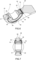
- the pin 54 helps to prevent the outer race 28 from rotating by engaging with a portion 58 of the flange 46 ( Fig. 5 ).
- the portion 58 of the flange 46 is shaped to engage either side of the pin 54 upon a rotational force being applied to the outer race 28.
- the portion 58 extends radially further than the rest of the flange 46 and comprises a notch 62 which engages with the pin 54.
- Other portion 58 shapes (and locations) may achieve the desired effect as long as they interact to prevent rotation of the outer race 28.
- two tabs could extend from the flange 46 to engage either side of the pin 54.
- the pin 54 may extend through a hole in the flange 46 to prevent the outer race 28 from rotating.
- the passage 56 and pin 54 may be any suitable complementary shape, for example cylindrical.
- the pin 54 is configured to prevent rotation of the nut 48. That is, the nut 48 comprises at least one notch 64 formed in its radially outer edge. The nut 48 is positioned so that one of the notches 64 lines up with the pin 54, to allow the pin 54 to engage with the notch 64. This helps to prevent the nut 48 from rotating.
- the pin 54 prevents rotation of the outer race 28 and nut 48. Small rotations of these components relative to the housing 32 may cause undesired wear of components of the bearing assembly 24, and the pin 54 prevents these rotations.
- the pin 54 is easy to install and is cheap to produce, and (as explained above) is easy to remove from the housing 32.
- the bearing assembly 24 may further comprise a cord 52 to further secure the various components of the bearing assembly 24 together.
- the pin 54 is hollow and has a passage 60 extending along its centre, and the cord 52 is received through the passage 60.
- the cord 52 is then configured to wrap around the housing 32 and its end secured (e.g., together).
- the cord 52 may be secured by placing the ends under tension and clamping them together using a suitable tool.
- An example of such a tool 55 is illustrated in Figure 8
- the cord 52 prevents the pin 54 from moving relative to the housing 32.
- the cord 52 may be formed from any suitable material, for example metal wire, and in the illustrated example a pair of metal wires twisted together.
- the cord 52 is advantageous because it is able to secure the assembly whilst being easy to remove when dismantling it.
- the pin 54 may be press-fit or adhesively bonded into the passage 56 of the housing 32.
- the bearing assembly 24 may also comprise sealant applied over outer surfaces of the bearing assembly 24.
- the sealant may be advantageously placed over gaps in the bearing assembly 24, for example applied on one or both of the axial ends of the bearing assembly 24 over one or more gaps between the outer race 28 and housing 32, the nut and the housing 32, and the nut 48 and the outer race 28. This can help to prevent corrosion and contamination of the bearing assembly 24.
- a radially outer surface 66 of the outer race 28 may have at least one groove 68, for example two grooves 68.
- the inner surface 34 of the housing 32 does not contact the outer race 28 where the grooves 68 are located.
- the grooves 68 are dimensioned to allow the portion of the outer race 28 in contact with the inner surface 34 to be centrally located and symmetrical relative to the centre of the spherical bearing 26. This helps to provide a symmetrical and even distribution of forces in the bearing assembly 24. Uneven force distribution in the bearing assembly 24 can lead to instability and wear within the bearing assembly 24 and the at least one groove 68 can help to prevent this.
- the grooves 68 are advantageous but not essential for the broadest aspects of the present disclosure.
- bearing assembly 24 In use, it may be necessary to deconstruct or disassemble the bearing assembly 24 to allow access to components of the bearing assembly 24, for example the spherical bearing 26, for maintenance. A method of deconstruction of the bearing assembly 24 will now be described.
- the cord 52 (if present) is removed from the bearing assembly 24 by any suitable method, for example the cord 52 is cut or untied from the housing 32.
- the pin 54 can then be pulled out of the passage 56.
- the nut 48 is then removed from the bearing assembly 24. If a screw thread 50 is used to secure the nut 48 to the outer race 28, the nut 48 is twisted relative to the outer race 28 to remove it. This can be achieved using any suitable tool.
- An example of such a tool 57 is illustrated in Figure 9 .
- the tool 57 comprises a socket wrench with an internal shape that matches the shape of the nut 48.
- the outer race 28 is now free to be removed from within the housing 32 from the side of the outer race 28 with the flange 46. Once the outer race 28 is removed from the housing 32, the spherical bearing 26 can be removed from within the outer race 28 if necessary, by any suitable method.
- the outer race 28 is first placed into the hollow interior of the housing 32 until the flange 46 abuts against the slot 40.
- the outer race 28 is arranged so that the notch 60 is aligned with the passage 56.
- the nut 48 is then threaded onto the outer race 28 until a pre-determined torque is achieved.
- the nut 48 is then further twisted/positioned a small amount so that a notch 64 of the nut 48 is aligned with the passage 56. Due to the use of multiple notches 64 this further extension does not significantly affect the pre-determined torque (it will not over-tighten the nut 48).
- the pin 54 is inserted into the passage 56 to engage with the notches 60, 64.
- the pin 54 may instead be partially inserted into the passage 56 before the nut 48 is fit onto the outer race 28, and then inserted fully after the nut 48 has been fit.
- the pin 54 may then be secured to the housing 32 by adhesive, if using.
- the cord 52 is threaded into the passage 62 in the pin 53 and wrapped round a portion of the housing 32. The ends of the cord 52 are then clamped together using any suitable tool to provide the desired tension of the cord 52 and secure the cord 52 in place.
- sealant is then applied over gaps on the bearing assembly 24 to help prevent corrosion/contamination in the bearing assembly 24.
- the arrangement of this disclosure allows the spherical bearing 26 to be more easily removed from the housing 32 than conventional methods.
- the bearing assembly 24 can be constructed and deconstructed using standard tools. The bearing assembly 24 is therefore easier to maintain, whilst still having the necessary structural integrity for high load applications, for example when used for an actuator in a helicopter.
Landscapes
- Engineering & Computer Science (AREA)
- General Engineering & Computer Science (AREA)
- Mechanical Engineering (AREA)
- Mounting Of Bearings Or Others (AREA)
Claims (11)
- Ensemble palier, comprenant :un boîtier (32);une bague extérieure annulaire (28) située au moins partiellement à l'intérieur du boîtier (32), la bague extérieure (28) ayant un axe central (X) et comprenant une bride (46) au niveau d'une première extrémité axiale, dans lequel la bride (46) est configurée pour empêcher le mouvement de la bague extérieure (28) par rapport au boîtier (32) dans une première direction axiale ;un palier (26) situé au moins partiellement à l'intérieur du chemin de palier extérieur (28) ;un écrou (48) configuré pour être fixé à une seconde extrémité axiale de la bague extérieure (28), dans lequel l'écrou (48) est configuré pour empêcher le déplacement de la bague extérieure (28) par rapport au boîtier (32) dans une seconde direction axiale, la seconde direction axiale étant opposée à la première direction axiale ; etune broche (54) configurée pour s'étendre à travers le boîtier (32), dans lequel la bride (46) comprend une encoche (62) ou un trou et la broche (54) étant configurée pour s'insérer dans l'encoche (62) ou dans le trou de la bride (46) pour empêcher la bague extérieure (28) de tourner, et dans lequel l'écrou (48) comprend au moins une encoche (64) et la broche (54) étant configurée pour s'insérer dans au moins une encoche (64) d'un écrou (48) pour empêcher l'écrou (48) de tourner ;caractérisé en ce quele boîtier (32) comprend une première fente annulaire (38) pour recevoir l'écrou (48), et l'écrou (48) étant configuré pour venir en butée contre une surface de la première fente (38).
- Ensemble palier selon la revendication 1, dans lequel le palier (26) est un palier sphérique (26).
- Ensemble palier selon la revendication 1 ou 2, dans lequel l'écrou (48) et la bague extérieure (28) ont des filetages complémentaires (50) de sorte que l'écrou (48) est configuré pour se visser sur une surface extérieure (30) de la bague extérieure (28).
- Ensemble palier selon une quelconque revendication précédente, dans lequel le boîtier (32) comprend en outre une seconde fente (40) pour recevoir la bride (46), dans lequel la bride (46) est configurée pour venir en butée contre une surface de la seconde fente (40).
- Ensemble palier selon la revendication 4, dans lequel la seconde fente (40) et la bride (46) sont toutes deux annulaires et/ou la seconde fente (40) est positionnée sur un côté opposé du boîtier (32) à la première fente (38).
- Ensemble palier selon une quelconque revendication précédente, dans lequel la bague extérieure (28) est une pièce généralement cylindrique qui définit l'axe central (X), et les première et seconde directions axiales s'étendent parallèlement à l'axe central (X).
- Ensemble palier selon une quelconque revendication précédente, comprenant en outre un cordon (52) s'étendant à travers la broche (54) et configuré pour être fixé au boîtier (32) pour empêcher la broche (54) de se déplacer.
- Procédé de construction de l'ensemble palier selon une quelconque revendication précédente, le procédé comprenant :l'insertion de la bague extérieure (28) dans le boîtier (32) jusqu'à ce que la bride (46) vienne en butée contre une surface du boîtier (32) ;la fixation de l'écrou (48) à la bague extérieure (28) pour fixer l'écrou (48) par rapport au boîtier (32) ;la disposition de la bague extérieure (28) de sorte que l'encoche (62) ou le trou de la bride (46) est aligné avec un passage (60) du boîtier (32) pour recevoir la broche (54) ; etl'insertion de la broche (54) à travers le boîtier (32) après les étapes d'insertion et de fixation.
- Procédé selon la revendication 8, dans lequel l'étape de fixation comporte le vissage de la bague extérieure (28) sur l'écrou (48) jusqu'à ce qu'un couple prédéterminé est atteint.
- Procédé selon la revendication 8 ou 9, comprenant en outre la torsion de l'écrou (48) après l'étape de fixation de sorte que l'au moins une encoche (64) de l'écrou (48) est alignée avec le passage (60) du boîtier (32) pour recevoir la broche (54).
- Procédé selon l'une quelconque des revendications 8 à 10, comprenant en outre l'insertion d'un cordon (52) à travers la broche (54) et la fixation du cordon (52) au boîtier (32).
Priority Applications (4)
| Application Number | Priority Date | Filing Date | Title |
|---|---|---|---|
| EP21205104.9A EP4174333B1 (fr) | 2021-10-27 | 2021-10-27 | Ensemble palier |
| BR102022015923-8A BR102022015923B1 (pt) | 2021-10-27 | 2022-08-11 | Conjunto de rolamento, e, método para construir o conjunto de rolamento |
| CA3173784A CA3173784A1 (fr) | 2021-10-27 | 2022-09-09 | Ensemble palier |
| US17/972,905 US12196251B2 (en) | 2021-10-27 | 2022-10-25 | Bearing assembly |
Applications Claiming Priority (1)
| Application Number | Priority Date | Filing Date | Title |
|---|---|---|---|
| EP21205104.9A EP4174333B1 (fr) | 2021-10-27 | 2021-10-27 | Ensemble palier |
Publications (2)
| Publication Number | Publication Date |
|---|---|
| EP4174333A1 EP4174333A1 (fr) | 2023-05-03 |
| EP4174333B1 true EP4174333B1 (fr) | 2024-07-17 |
Family
ID=78414258
Family Applications (1)
| Application Number | Title | Priority Date | Filing Date |
|---|---|---|---|
| EP21205104.9A Active EP4174333B1 (fr) | 2021-10-27 | 2021-10-27 | Ensemble palier |
Country Status (3)
| Country | Link |
|---|---|
| US (1) | US12196251B2 (fr) |
| EP (1) | EP4174333B1 (fr) |
| CA (1) | CA3173784A1 (fr) |
Family Cites Families (9)
| Publication number | Priority date | Publication date | Assignee | Title |
|---|---|---|---|---|
| US3516136A (en) | 1968-06-28 | 1970-06-23 | Kahr Bearing Corp | Self-aligning bearing and method of forming and mounting thereof |
| US4243192A (en) * | 1978-12-04 | 1981-01-06 | Mcdonnell Douglas Corporation | Ball pivot thrust bearing flex joint |
| US4319788A (en) * | 1980-02-19 | 1982-03-16 | Southwest Products Co. | Means and techniques useful in mounting self-aligning bearings |
| JP2002106556A (ja) | 2000-09-26 | 2002-04-10 | Minebea Co Ltd | 球面滑り軸受の固定構造及びその固定方法 |
| US9951808B2 (en) | 2013-11-15 | 2018-04-24 | Bell Helicopter Textron Inc. | Elastomeric spherical bearing assembly and structural member incorporating the same |
| US9366296B2 (en) * | 2014-01-13 | 2016-06-14 | The Boeing Company | Swaging features that lock retaining elements for bearings |
| EP3076039B1 (fr) | 2015-04-03 | 2019-06-05 | Goodrich Actuation Systems SAS | Roulements à rotule |
| US9885386B2 (en) * | 2015-06-15 | 2018-02-06 | General Electric Company | Bearing assembly |
| US9976599B2 (en) * | 2016-06-27 | 2018-05-22 | The Boeing Company | Countersunk threaded bearing and method of installation |
-
2021
- 2021-10-27 EP EP21205104.9A patent/EP4174333B1/fr active Active
-
2022
- 2022-09-09 CA CA3173784A patent/CA3173784A1/fr active Pending
- 2022-10-25 US US17/972,905 patent/US12196251B2/en active Active
Also Published As
| Publication number | Publication date |
|---|---|
| BR102022015923A2 (pt) | 2023-05-09 |
| US12196251B2 (en) | 2025-01-14 |
| CA3173784A1 (fr) | 2023-04-27 |
| US20230417282A1 (en) | 2023-12-28 |
| EP4174333A1 (fr) | 2023-05-03 |
Similar Documents
| Publication | Publication Date | Title |
|---|---|---|
| CA2184405C (fr) | Dispositif de montage | |
| US5417501A (en) | Bearing assemblies for rotating shafts | |
| JP2001514994A (ja) | 航空機用プロペラ羽根の取付保持のための予圧を付加した軸受アセンブリ | |
| CN1212320A (zh) | 用于高速涡轮机的压气机叶轮固定装置 | |
| CN209774503U (zh) | 一种液体火箭发动机涡轮泵装配轴系止动装置 | |
| US11719283B2 (en) | Axially clamping rotating engine components | |
| JP2022505311A (ja) | 損傷したねじ山を修繕するための方法および工具 | |
| EP2267290A2 (fr) | Ensemble de serrage | |
| EP2831434B1 (fr) | Palier sphérique comprenant un support | |
| EP4174333B1 (fr) | Ensemble palier | |
| WO2019211001A1 (fr) | Moteur électrique comprenant un accouplement entre l'arbre de rotor et l'arbre d'un capteur angulaire | |
| US7309187B2 (en) | Releasable keyless bushing assembly | |
| EP3473873B1 (fr) | Accouplements filetés avec verrouillage | |
| EP3276197B1 (fr) | Dispositif de fixation de palier pour un palier monté en rotation sur un arbre | |
| EP3384183B1 (fr) | Porte-satellites pour étage d'engrenage d'un engrenage planétaire et procédé de précontrainte | |
| EP3693579B1 (fr) | Ensemble et procédé de verrouillage de démarreur | |
| EP3611391B1 (fr) | Accouplements filetés avec verrouillage | |
| EP3760872B1 (fr) | Pompe à vide pourvue d'un agencement de fixation destiné à l'application de la pompe à une structure de fixation ainsi qu'un poste de pompage doté d'une telle pompe à vide montée sur celui-ci | |
| EP3423724B1 (fr) | Appareil et procédé de préchargement d'ensembles paliers | |
| EP3715244B1 (fr) | Raccord boulonné pour ensemble roues | |
| EP0843634B1 (fr) | Precharge de roulements | |
| CN110167715B (zh) | 用于对准结构构件中的孔的对准工具 | |
| US20250116301A1 (en) | Disc coupling | |
| CN112196868A (zh) | 装配螺栓连接结构 | |
| US20260034651A1 (en) | Systems and methods for removing tapered bushing connectors from torque rod assemblies |
Legal Events
| Date | Code | Title | Description |
|---|---|---|---|
| PUAI | Public reference made under article 153(3) epc to a published international application that has entered the european phase |
Free format text: ORIGINAL CODE: 0009012 |
|
| STAA | Information on the status of an ep patent application or granted ep patent |
Free format text: STATUS: THE APPLICATION HAS BEEN PUBLISHED |
|
| AK | Designated contracting states |
Kind code of ref document: A1 Designated state(s): AL AT BE BG CH CY CZ DE DK EE ES FI FR GB GR HR HU IE IS IT LI LT LU LV MC MK MT NL NO PL PT RO RS SE SI SK SM TR |
|
| STAA | Information on the status of an ep patent application or granted ep patent |
Free format text: STATUS: REQUEST FOR EXAMINATION WAS MADE |
|
| 17P | Request for examination filed |
Effective date: 20231103 |
|
| RBV | Designated contracting states (corrected) |
Designated state(s): AL AT BE BG CH CY CZ DE DK EE ES FI FR GB GR HR HU IE IS IT LI LT LU LV MC MK MT NL NO PL PT RO RS SE SI SK SM TR |
|
| GRAP | Despatch of communication of intention to grant a patent |
Free format text: ORIGINAL CODE: EPIDOSNIGR1 |
|
| STAA | Information on the status of an ep patent application or granted ep patent |
Free format text: STATUS: GRANT OF PATENT IS INTENDED |
|
| INTG | Intention to grant announced |
Effective date: 20240209 |
|
| GRAS | Grant fee paid |
Free format text: ORIGINAL CODE: EPIDOSNIGR3 |
|
| GRAA | (expected) grant |
Free format text: ORIGINAL CODE: 0009210 |
|
| STAA | Information on the status of an ep patent application or granted ep patent |
Free format text: STATUS: THE PATENT HAS BEEN GRANTED |
|
| AK | Designated contracting states |
Kind code of ref document: B1 Designated state(s): AL AT BE BG CH CY CZ DE DK EE ES FI FR GB GR HR HU IE IS IT LI LT LU LV MC MK MT NL NO PL PT RO RS SE SI SK SM TR |
|
| REG | Reference to a national code |
Ref country code: CH Ref legal event code: EP |
|
| REG | Reference to a national code |
Ref country code: DE Ref legal event code: R096 Ref document number: 602021015750 Country of ref document: DE |
|
| REG | Reference to a national code |
Ref country code: IE Ref legal event code: FG4D |
|
| REG | Reference to a national code |
Ref country code: LT Ref legal event code: MG9D |
|
| REG | Reference to a national code |
Ref country code: NL Ref legal event code: MP Effective date: 20240717 |
|
| PG25 | Lapsed in a contracting state [announced via postgrant information from national office to epo] |
Ref country code: PT Free format text: LAPSE BECAUSE OF FAILURE TO SUBMIT A TRANSLATION OF THE DESCRIPTION OR TO PAY THE FEE WITHIN THE PRESCRIBED TIME-LIMIT Effective date: 20241118 |
|
| REG | Reference to a national code |
Ref country code: AT Ref legal event code: MK05 Ref document number: 1704400 Country of ref document: AT Kind code of ref document: T Effective date: 20240717 |
|
| PG25 | Lapsed in a contracting state [announced via postgrant information from national office to epo] |
Ref country code: NL Free format text: LAPSE BECAUSE OF FAILURE TO SUBMIT A TRANSLATION OF THE DESCRIPTION OR TO PAY THE FEE WITHIN THE PRESCRIBED TIME-LIMIT Effective date: 20240717 |
|
| PG25 | Lapsed in a contracting state [announced via postgrant information from national office to epo] |
Ref country code: PT Free format text: LAPSE BECAUSE OF FAILURE TO SUBMIT A TRANSLATION OF THE DESCRIPTION OR TO PAY THE FEE WITHIN THE PRESCRIBED TIME-LIMIT Effective date: 20241118 Ref country code: NL Free format text: LAPSE BECAUSE OF FAILURE TO SUBMIT A TRANSLATION OF THE DESCRIPTION OR TO PAY THE FEE WITHIN THE PRESCRIBED TIME-LIMIT Effective date: 20240717 |
|
| PG25 | Lapsed in a contracting state [announced via postgrant information from national office to epo] |
Ref country code: NO Free format text: LAPSE BECAUSE OF FAILURE TO SUBMIT A TRANSLATION OF THE DESCRIPTION OR TO PAY THE FEE WITHIN THE PRESCRIBED TIME-LIMIT Effective date: 20241017 |
|
| PG25 | Lapsed in a contracting state [announced via postgrant information from national office to epo] |
Ref country code: FI Free format text: LAPSE BECAUSE OF FAILURE TO SUBMIT A TRANSLATION OF THE DESCRIPTION OR TO PAY THE FEE WITHIN THE PRESCRIBED TIME-LIMIT Effective date: 20240717 Ref country code: PL Free format text: LAPSE BECAUSE OF FAILURE TO SUBMIT A TRANSLATION OF THE DESCRIPTION OR TO PAY THE FEE WITHIN THE PRESCRIBED TIME-LIMIT Effective date: 20240717 Ref country code: GR Free format text: LAPSE BECAUSE OF FAILURE TO SUBMIT A TRANSLATION OF THE DESCRIPTION OR TO PAY THE FEE WITHIN THE PRESCRIBED TIME-LIMIT Effective date: 20241018 |
|
| PG25 | Lapsed in a contracting state [announced via postgrant information from national office to epo] |
Ref country code: BG Free format text: LAPSE BECAUSE OF FAILURE TO SUBMIT A TRANSLATION OF THE DESCRIPTION OR TO PAY THE FEE WITHIN THE PRESCRIBED TIME-LIMIT Effective date: 20240717 |
|
| PG25 | Lapsed in a contracting state [announced via postgrant information from national office to epo] |
Ref country code: LV Free format text: LAPSE BECAUSE OF FAILURE TO SUBMIT A TRANSLATION OF THE DESCRIPTION OR TO PAY THE FEE WITHIN THE PRESCRIBED TIME-LIMIT Effective date: 20240717 |
|
| PG25 | Lapsed in a contracting state [announced via postgrant information from national office to epo] |
Ref country code: IS Free format text: LAPSE BECAUSE OF FAILURE TO SUBMIT A TRANSLATION OF THE DESCRIPTION OR TO PAY THE FEE WITHIN THE PRESCRIBED TIME-LIMIT Effective date: 20241117 Ref country code: AT Free format text: LAPSE BECAUSE OF FAILURE TO SUBMIT A TRANSLATION OF THE DESCRIPTION OR TO PAY THE FEE WITHIN THE PRESCRIBED TIME-LIMIT Effective date: 20240717 |
|
| PG25 | Lapsed in a contracting state [announced via postgrant information from national office to epo] |
Ref country code: HR Free format text: LAPSE BECAUSE OF FAILURE TO SUBMIT A TRANSLATION OF THE DESCRIPTION OR TO PAY THE FEE WITHIN THE PRESCRIBED TIME-LIMIT Effective date: 20240717 |
|
| PG25 | Lapsed in a contracting state [announced via postgrant information from national office to epo] |
Ref country code: RS Free format text: LAPSE BECAUSE OF FAILURE TO SUBMIT A TRANSLATION OF THE DESCRIPTION OR TO PAY THE FEE WITHIN THE PRESCRIBED TIME-LIMIT Effective date: 20241017 Ref country code: ES Free format text: LAPSE BECAUSE OF FAILURE TO SUBMIT A TRANSLATION OF THE DESCRIPTION OR TO PAY THE FEE WITHIN THE PRESCRIBED TIME-LIMIT Effective date: 20240717 |
|
| PG25 | Lapsed in a contracting state [announced via postgrant information from national office to epo] |
Ref country code: RS Free format text: LAPSE BECAUSE OF FAILURE TO SUBMIT A TRANSLATION OF THE DESCRIPTION OR TO PAY THE FEE WITHIN THE PRESCRIBED TIME-LIMIT Effective date: 20241017 Ref country code: PL Free format text: LAPSE BECAUSE OF FAILURE TO SUBMIT A TRANSLATION OF THE DESCRIPTION OR TO PAY THE FEE WITHIN THE PRESCRIBED TIME-LIMIT Effective date: 20240717 Ref country code: NO Free format text: LAPSE BECAUSE OF FAILURE TO SUBMIT A TRANSLATION OF THE DESCRIPTION OR TO PAY THE FEE WITHIN THE PRESCRIBED TIME-LIMIT Effective date: 20241017 Ref country code: LV Free format text: LAPSE BECAUSE OF FAILURE TO SUBMIT A TRANSLATION OF THE DESCRIPTION OR TO PAY THE FEE WITHIN THE PRESCRIBED TIME-LIMIT Effective date: 20240717 Ref country code: IS Free format text: LAPSE BECAUSE OF FAILURE TO SUBMIT A TRANSLATION OF THE DESCRIPTION OR TO PAY THE FEE WITHIN THE PRESCRIBED TIME-LIMIT Effective date: 20241117 Ref country code: HR Free format text: LAPSE BECAUSE OF FAILURE TO SUBMIT A TRANSLATION OF THE DESCRIPTION OR TO PAY THE FEE WITHIN THE PRESCRIBED TIME-LIMIT Effective date: 20240717 Ref country code: GR Free format text: LAPSE BECAUSE OF FAILURE TO SUBMIT A TRANSLATION OF THE DESCRIPTION OR TO PAY THE FEE WITHIN THE PRESCRIBED TIME-LIMIT Effective date: 20241018 Ref country code: FI Free format text: LAPSE BECAUSE OF FAILURE TO SUBMIT A TRANSLATION OF THE DESCRIPTION OR TO PAY THE FEE WITHIN THE PRESCRIBED TIME-LIMIT Effective date: 20240717 Ref country code: ES Free format text: LAPSE BECAUSE OF FAILURE TO SUBMIT A TRANSLATION OF THE DESCRIPTION OR TO PAY THE FEE WITHIN THE PRESCRIBED TIME-LIMIT Effective date: 20240717 Ref country code: BG Free format text: LAPSE BECAUSE OF FAILURE TO SUBMIT A TRANSLATION OF THE DESCRIPTION OR TO PAY THE FEE WITHIN THE PRESCRIBED TIME-LIMIT Effective date: 20240717 Ref country code: AT Free format text: LAPSE BECAUSE OF FAILURE TO SUBMIT A TRANSLATION OF THE DESCRIPTION OR TO PAY THE FEE WITHIN THE PRESCRIBED TIME-LIMIT Effective date: 20240717 |
|
| PG25 | Lapsed in a contracting state [announced via postgrant information from national office to epo] |
Ref country code: RO Free format text: LAPSE BECAUSE OF FAILURE TO SUBMIT A TRANSLATION OF THE DESCRIPTION OR TO PAY THE FEE WITHIN THE PRESCRIBED TIME-LIMIT Effective date: 20240717 Ref country code: SM Free format text: LAPSE BECAUSE OF FAILURE TO SUBMIT A TRANSLATION OF THE DESCRIPTION OR TO PAY THE FEE WITHIN THE PRESCRIBED TIME-LIMIT Effective date: 20240717 Ref country code: DK Free format text: LAPSE BECAUSE OF FAILURE TO SUBMIT A TRANSLATION OF THE DESCRIPTION OR TO PAY THE FEE WITHIN THE PRESCRIBED TIME-LIMIT Effective date: 20240717 |
|
| REG | Reference to a national code |
Ref country code: DE Ref legal event code: R097 Ref document number: 602021015750 Country of ref document: DE |
|
| PG25 | Lapsed in a contracting state [announced via postgrant information from national office to epo] |
Ref country code: EE Free format text: LAPSE BECAUSE OF FAILURE TO SUBMIT A TRANSLATION OF THE DESCRIPTION OR TO PAY THE FEE WITHIN THE PRESCRIBED TIME-LIMIT Effective date: 20240717 |
|
| PG25 | Lapsed in a contracting state [announced via postgrant information from national office to epo] |
Ref country code: CZ Free format text: LAPSE BECAUSE OF FAILURE TO SUBMIT A TRANSLATION OF THE DESCRIPTION OR TO PAY THE FEE WITHIN THE PRESCRIBED TIME-LIMIT Effective date: 20240717 |
|
| PG25 | Lapsed in a contracting state [announced via postgrant information from national office to epo] |
Ref country code: SK Free format text: LAPSE BECAUSE OF FAILURE TO SUBMIT A TRANSLATION OF THE DESCRIPTION OR TO PAY THE FEE WITHIN THE PRESCRIBED TIME-LIMIT Effective date: 20240717 |
|
| PLBE | No opposition filed within time limit |
Free format text: ORIGINAL CODE: 0009261 |
|
| STAA | Information on the status of an ep patent application or granted ep patent |
Free format text: STATUS: NO OPPOSITION FILED WITHIN TIME LIMIT |
|
| REG | Reference to a national code |
Ref country code: CH Ref legal event code: PL |
|
| 26N | No opposition filed |
Effective date: 20250422 |
|
| PG25 | Lapsed in a contracting state [announced via postgrant information from national office to epo] |
Ref country code: MC Free format text: LAPSE BECAUSE OF FAILURE TO SUBMIT A TRANSLATION OF THE DESCRIPTION OR TO PAY THE FEE WITHIN THE PRESCRIBED TIME-LIMIT Effective date: 20240717 |
|
| PG25 | Lapsed in a contracting state [announced via postgrant information from national office to epo] |
Ref country code: LU Free format text: LAPSE BECAUSE OF NON-PAYMENT OF DUE FEES Effective date: 20241027 Ref country code: BE Free format text: LAPSE BECAUSE OF NON-PAYMENT OF DUE FEES Effective date: 20241031 |
|
| PG25 | Lapsed in a contracting state [announced via postgrant information from national office to epo] |
Ref country code: CH Free format text: LAPSE BECAUSE OF NON-PAYMENT OF DUE FEES Effective date: 20241031 |
|
| REG | Reference to a national code |
Ref country code: BE Ref legal event code: MM Effective date: 20241031 |
|
| PG25 | Lapsed in a contracting state [announced via postgrant information from national office to epo] |
Ref country code: SE Free format text: LAPSE BECAUSE OF FAILURE TO SUBMIT A TRANSLATION OF THE DESCRIPTION OR TO PAY THE FEE WITHIN THE PRESCRIBED TIME-LIMIT Effective date: 20240717 |
|
| PG25 | Lapsed in a contracting state [announced via postgrant information from national office to epo] |
Ref country code: IE Free format text: LAPSE BECAUSE OF NON-PAYMENT OF DUE FEES Effective date: 20241027 |
|
| PGFP | Annual fee paid to national office [announced via postgrant information from national office to epo] |
Ref country code: DE Payment date: 20251015 Year of fee payment: 5 |
|
| PGFP | Annual fee paid to national office [announced via postgrant information from national office to epo] |
Ref country code: GB Payment date: 20251023 Year of fee payment: 5 |
|
| PG25 | Lapsed in a contracting state [announced via postgrant information from national office to epo] |
Ref country code: IT Free format text: LAPSE BECAUSE OF NON-PAYMENT OF DUE FEES Effective date: 20241027 |
|
| PGFP | Annual fee paid to national office [announced via postgrant information from national office to epo] |
Ref country code: FR Payment date: 20251028 Year of fee payment: 5 |
|
| PG25 | Lapsed in a contracting state [announced via postgrant information from national office to epo] |
Ref country code: CY Free format text: LAPSE BECAUSE OF FAILURE TO SUBMIT A TRANSLATION OF THE DESCRIPTION OR TO PAY THE FEE WITHIN THE PRESCRIBED TIME-LIMIT; INVALID AB INITIO Effective date: 20211027 |
|
| PG25 | Lapsed in a contracting state [announced via postgrant information from national office to epo] |
Ref country code: HU Free format text: LAPSE BECAUSE OF FAILURE TO SUBMIT A TRANSLATION OF THE DESCRIPTION OR TO PAY THE FEE WITHIN THE PRESCRIBED TIME-LIMIT; INVALID AB INITIO Effective date: 20211027 |
|
| PG25 | Lapsed in a contracting state [announced via postgrant information from national office to epo] |
Ref country code: IT Free format text: LAPSE BECAUSE OF NON-PAYMENT OF DUE FEES Effective date: 20241027 |
|
| PGFP | Annual fee paid to national office [announced via postgrant information from national office to epo] |
Ref country code: IT Payment date: 20251007 Year of fee payment: 5 |
|
| PGRI | Patent reinstated in contracting state [announced from national office to epo] |
Ref country code: IT Effective date: 20241031 |