EP4174366A1 - Fahrzeuglichtleiter und fahrzeuglampe - Google Patents
Fahrzeuglichtleiter und fahrzeuglampe Download PDFInfo
- Publication number
- EP4174366A1 EP4174366A1 EP21833884.6A EP21833884A EP4174366A1 EP 4174366 A1 EP4174366 A1 EP 4174366A1 EP 21833884 A EP21833884 A EP 21833884A EP 4174366 A1 EP4174366 A1 EP 4174366A1
- Authority
- EP
- European Patent Office
- Prior art keywords
- vehicle
- light
- base portion
- light guide
- prism portions
- Prior art date
- Legal status (The legal status is an assumption and is not a legal conclusion. Google has not performed a legal analysis and makes no representation as to the accuracy of the status listed.)
- Pending
Links
Images


Classifications
-
- F—MECHANICAL ENGINEERING; LIGHTING; HEATING; WEAPONS; BLASTING
- F21—LIGHTING
- F21S—NON-PORTABLE LIGHTING DEVICES; SYSTEMS THEREOF; VEHICLE LIGHTING DEVICES SPECIALLY ADAPTED FOR VEHICLE EXTERIORS
- F21S43/00—Signalling devices specially adapted for vehicle exteriors, e.g. brake lamps, direction indicator lights or reversing lights
- F21S43/20—Signalling devices specially adapted for vehicle exteriors, e.g. brake lamps, direction indicator lights or reversing lights characterised by refractors, transparent cover plates, light guides or filters
- F21S43/235—Light guides
- F21S43/236—Light guides characterised by the shape of the light guide
- F21S43/237—Light guides characterised by the shape of the light guide rod-shaped
-
- F—MECHANICAL ENGINEERING; LIGHTING; HEATING; WEAPONS; BLASTING
- F21—LIGHTING
- F21S—NON-PORTABLE LIGHTING DEVICES; SYSTEMS THEREOF; VEHICLE LIGHTING DEVICES SPECIALLY ADAPTED FOR VEHICLE EXTERIORS
- F21S43/00—Signalling devices specially adapted for vehicle exteriors, e.g. brake lamps, direction indicator lights or reversing lights
- F21S43/10—Signalling devices specially adapted for vehicle exteriors, e.g. brake lamps, direction indicator lights or reversing lights characterised by the light source
- F21S43/13—Signalling devices specially adapted for vehicle exteriors, e.g. brake lamps, direction indicator lights or reversing lights characterised by the light source characterised by the type of light source
- F21S43/14—Light emitting diodes [LED]
-
- F—MECHANICAL ENGINEERING; LIGHTING; HEATING; WEAPONS; BLASTING
- F21—LIGHTING
- F21S—NON-PORTABLE LIGHTING DEVICES; SYSTEMS THEREOF; VEHICLE LIGHTING DEVICES SPECIALLY ADAPTED FOR VEHICLE EXTERIORS
- F21S43/00—Signalling devices specially adapted for vehicle exteriors, e.g. brake lamps, direction indicator lights or reversing lights
- F21S43/20—Signalling devices specially adapted for vehicle exteriors, e.g. brake lamps, direction indicator lights or reversing lights characterised by refractors, transparent cover plates, light guides or filters
- F21S43/235—Light guides
- F21S43/236—Light guides characterised by the shape of the light guide
- F21S43/241—Light guides characterised by the shape of the light guide of complex shape
-
- F—MECHANICAL ENGINEERING; LIGHTING; HEATING; WEAPONS; BLASTING
- F21—LIGHTING
- F21S—NON-PORTABLE LIGHTING DEVICES; SYSTEMS THEREOF; VEHICLE LIGHTING DEVICES SPECIALLY ADAPTED FOR VEHICLE EXTERIORS
- F21S43/00—Signalling devices specially adapted for vehicle exteriors, e.g. brake lamps, direction indicator lights or reversing lights
- F21S43/20—Signalling devices specially adapted for vehicle exteriors, e.g. brake lamps, direction indicator lights or reversing lights characterised by refractors, transparent cover plates, light guides or filters
- F21S43/235—Light guides
- F21S43/242—Light guides characterised by the emission area
- F21S43/245—Light guides characterised by the emission area emitting light from one or more of its major surfaces
-
- F—MECHANICAL ENGINEERING; LIGHTING; HEATING; WEAPONS; BLASTING
- F21—LIGHTING
- F21S—NON-PORTABLE LIGHTING DEVICES; SYSTEMS THEREOF; VEHICLE LIGHTING DEVICES SPECIALLY ADAPTED FOR VEHICLE EXTERIORS
- F21S43/00—Signalling devices specially adapted for vehicle exteriors, e.g. brake lamps, direction indicator lights or reversing lights
- F21S43/20—Signalling devices specially adapted for vehicle exteriors, e.g. brake lamps, direction indicator lights or reversing lights characterised by refractors, transparent cover plates, light guides or filters
- F21S43/235—Light guides
- F21S43/249—Light guides with two or more light sources being coupled into the light guide
-
- F—MECHANICAL ENGINEERING; LIGHTING; HEATING; WEAPONS; BLASTING
- F21—LIGHTING
- F21W—INDEXING SCHEME ASSOCIATED WITH SUBCLASSES F21K, F21L, F21S and F21V, RELATING TO USES OR APPLICATIONS OF LIGHTING DEVICES OR SYSTEMS
- F21W2103/00—Exterior vehicle lighting devices for signalling purposes
- F21W2103/10—Position lights
-
- G—PHYSICS
- G02—OPTICS
- G02B—OPTICAL ELEMENTS, SYSTEMS OR APPARATUS
- G02B6/00—Light guides; Structural details of arrangements comprising light guides and other optical elements, e.g. couplings
- G02B6/0001—Light guides; Structural details of arrangements comprising light guides and other optical elements, e.g. couplings specially adapted for lighting devices or systems
- G02B6/0005—Light guides; Structural details of arrangements comprising light guides and other optical elements, e.g. couplings specially adapted for lighting devices or systems the light guides being of the fibre type
- G02B6/0006—Coupling light into the fibre
-
- G—PHYSICS
- G02—OPTICS
- G02B—OPTICAL ELEMENTS, SYSTEMS OR APPARATUS
- G02B6/00—Light guides; Structural details of arrangements comprising light guides and other optical elements, e.g. couplings
- G02B6/0001—Light guides; Structural details of arrangements comprising light guides and other optical elements, e.g. couplings specially adapted for lighting devices or systems
- G02B6/0005—Light guides; Structural details of arrangements comprising light guides and other optical elements, e.g. couplings specially adapted for lighting devices or systems the light guides being of the fibre type
- G02B6/001—Light guides; Structural details of arrangements comprising light guides and other optical elements, e.g. couplings specially adapted for lighting devices or systems the light guides being of the fibre type the light being emitted along at least a portion of the lateral surface of the fibre
-
- G—PHYSICS
- G02—OPTICS
- G02B—OPTICAL ELEMENTS, SYSTEMS OR APPARATUS
- G02B6/00—Light guides; Structural details of arrangements comprising light guides and other optical elements, e.g. couplings
- G02B6/0001—Light guides; Structural details of arrangements comprising light guides and other optical elements, e.g. couplings specially adapted for lighting devices or systems
- G02B6/0011—Light guides; Structural details of arrangements comprising light guides and other optical elements, e.g. couplings specially adapted for lighting devices or systems the light guides being planar or of plate-like form
- G02B6/0013—Means for improving the coupling-in of light from the light source into the light guide
- G02B6/0023—Means for improving the coupling-in of light from the light source into the light guide provided by one optical element, or plurality thereof, placed between the light guide and the light source, or around the light source
- G02B6/0028—Light guide, e.g. taper
-
- G—PHYSICS
- G02—OPTICS
- G02B—OPTICAL ELEMENTS, SYSTEMS OR APPARATUS
- G02B6/00—Light guides; Structural details of arrangements comprising light guides and other optical elements, e.g. couplings
- G02B6/0001—Light guides; Structural details of arrangements comprising light guides and other optical elements, e.g. couplings specially adapted for lighting devices or systems
- G02B6/0011—Light guides; Structural details of arrangements comprising light guides and other optical elements, e.g. couplings specially adapted for lighting devices or systems the light guides being planar or of plate-like form
- G02B6/0033—Means for improving the coupling-out of light from the light guide
- G02B6/0035—Means for improving the coupling-out of light from the light guide provided on the surface of the light guide or in the bulk of it
- G02B6/0038—Linear indentations or grooves, e.g. arc-shaped grooves or meandering grooves, extending over the full length or width of the light guide
-
- G—PHYSICS
- G02—OPTICS
- G02B—OPTICAL ELEMENTS, SYSTEMS OR APPARATUS
- G02B6/00—Light guides; Structural details of arrangements comprising light guides and other optical elements, e.g. couplings
- G02B6/0001—Light guides; Structural details of arrangements comprising light guides and other optical elements, e.g. couplings specially adapted for lighting devices or systems
- G02B6/0011—Light guides; Structural details of arrangements comprising light guides and other optical elements, e.g. couplings specially adapted for lighting devices or systems the light guides being planar or of plate-like form
- G02B6/0033—Means for improving the coupling-out of light from the light guide
- G02B6/0058—Means for improving the coupling-out of light from the light guide varying in density, size, shape or depth along the light guide
- G02B6/0061—Means for improving the coupling-out of light from the light guide varying in density, size, shape or depth along the light guide to provide homogeneous light output intensity
Definitions
- the present invention relates to a vehicle light guide and a vehicle lamp.
- a vehicle lamp equipped with a vehicle light guide that guides light from a light source so as to be emitted is known (see, for example, Patent Literature 1).
- a vehicle light guide In such a vehicle light guide, light emitted from a light source is incident from one end of the longitudinal direction of the vehicle light guide, and the incident light is guided along the longitudinal direction and emitted from a side face.
- Patent Literature 1 Japanese Patent Laid-open Publication No. 2014-7014
- the present invention was made in view of the above, and an object of the invention is to provide a vehicle light guide and a vehicle lamp capable of emitting light which is uniform in color and illumination in the longitudinal direction.
- a vehicle light guide includes: a rod-shaped base portion disposed at a front portion of a vehicle in a state of being installed in the vehicle, the base portion having a curved portion curved rearward from a front face of the vehicle toward a side face at an outer side of the vehicle, and guides light from a light source so as to be emitted from an emission surface at a front side facing forward and sideway of the vehicle; a plurality of prism portions arranged along a longitudinal direction on a back face side with respect to the emission surface of the base portion and that reflect light toward the front side; and a diffusing part positioned in a range including at least the curved portion in the longitudinal direction of the base portion and provided in a strip form along the prism portions on a bottom face side of the prism portions, and that diffuses light.
- the prism portions provided in the curved portion of the base portion have a smaller dimension in a height direction than those provided on the front face side of the base portion.
- the diffusing part may have a uniform dimension in a width direction at least in a portion provided in the curved portion.
- the diffusing part may have a shape whose end portion gradually tapers toward the front face side of the vehicle.
- the diffusing part may be an embossed part formed on a surface of the base portion.
- a vehicle lamp according to the present invention includes: a light source; and the vehicle light guide to guide light from the light source so as to be emitted in front of the vehicle.
- a vehicle light guide and a vehicle lamp that can emit light in uniform color and illumination in the longitudinal direction.
- each of the front-rear, up-down, and right-left directions is a direction in an in-vehicle state where a vehicle light guide and a vehicle lamp are installed in a vehicle, and indicates a direction when the traveling direction of the vehicle is viewed from the driver's seat.
- the up-down direction is parallel to the vertical direction and the left-right direction is the horizontal direction.
- the side facing the front and side of the vehicle is the front side, and the back side of the front side, viewed from the vertical direction, is the rear side.
- FIG. 1 is a front view showing one example of a vehicle lamp 100 according to the present embodiment.
- FIG. 2 is an A-A arrow cross-sectional view in FIG. 1 .
- the vehicle lamp 100 has light sources 10, 15 and a vehicle light guide 20.
- the vehicle lamp 100 includes, for example, a clearance lamp.
- the vehicle lamp 100 is located in a light chamber, which is divided by a lamp housing 30 and a lamp lens 40.
- lamps for low beams, lamps for high beams, fog lamps, cornering lamps, etc. may be located in the light chamber, for example.
- the vehicle lamp 100 is mounted on both the left and right sides of the front of the vehicle.
- the present embodiment is described below with an example in which the vehicle lamp is mounted on the right side of the front of a vehicle.
- the vehicle lamp mounted on the left side of the vehicle is configured to have a left-right symmetry with the vehicle lamp 100, so that a similar explanation can be applied.
- the outside of the vehicle is the right side and the inside of the vehicle is the left side.
- the outside of the vehicle is the left side and the inside of the vehicle is the right side.
- the light sources 10, 15 provide white light, for example, with the vehicle light guide 20.
- the light sources 10, 15 are a semiconductor type light source, such as an LED, for example.
- One or more light sources can be provided. In the present embodiment, two light sources 10, 15 are provided.
- One or more than three light sources may be provided.
- the light sources 10, 15 have light emitting surfaces 11, 16 that emit light, respectively.
- the light emitting surface 11 is disposed so as to face an incidence surface 21a of a base portion 21 of the vehicle light guide 20 described later.
- the light emitting surface 16 is disposed so as to face an incidence surface 24a of a merging portion 24 of the vehicle light guide 20 described later.
- the vehicle light guide 20 has a base portion 21, prism portions 22, a scattering part 23, and a merging portion 24.
- the base portion 21 is rod-shaped and is located on the front side of the vehicle.
- the base portion 21 has a first straight portion 21c located on the front face side of the vehicle, a curved portion 21d that curves rearward from the front face side to the side face of the vehicle, and a second straight portion 21e located on the side face of the vehicle.
- the base portion 21 has the incidence surface 21a at the rear end of the first straight portion 21c.
- the incidence surface 21a receives light from the light source 10.
- the base portion 21 has an emission surface 21b on the front side throughout the first straight portion 21c, the curved portion 21d and a second straight portion 21e.
- the emission surface 21b emits the guided light to the front side.
- the prism portions 22 are located on the back side of the base portion 21 with respect to the emission surface 21b.
- the prism portions 22 are arranged along a longitudinal direction of the base portion 21 and reflect light to the front side.
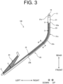
- FIG. 3 schematically shows an example of the vehicle lamp 100 viewed from below.
- FIG. 4 is a B-B arrow cross-sectional view in FIG. 3 .
- the prism portions 22 have a flat bottom.
- the direction orthogonal to the bottom of the prism portions 22 is denoted as a height direction of the prism portions 22.
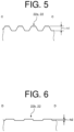
- FIG. 5 is a C-C arrow cross-sectional view in FIG. 3 .
- FIG. 6 is a D-D arrow cross-sectional view in FIG. 3 .
- the prism portions 22 provided in the curved portion 21d of the base portion 21 have a smaller dimension in the height direction thereof (hereinafter referred to as "height") than those provided on the front face side of the base portion 21.
- the height h2 of the prism portions 22 at the end on the side face side is smaller than one-tenth of the height h1 of the prism portions 22 at the end on the front face side (see FIG. 5 ).
- the height h2 of the prism portions 22 at the end on the side face side may be set to 0.1 mm or less, for example.
- the relationship between the height h1 and the height h2 is only an example and is not limited thereto.
- the prism portions 22 being formed so that it gradually increases in height from the end on the side face side to the end on the front side, the area of the reflective surface at the portion far from the light source 10 can be larger than the area of the reflective surface at the portion close to the light source 10.
- the amount of light emitted from the emission surface 21b can be adjusted to be uniform in the longitudinal direction.
- FIG. 7 is an enlarged view showing a main part of FIG. 3 .
- the scattering part 23 is provided in a strip along the prism portions 22.
- the scattering part 23 diffuses light traveling through the interior of the base portion 21 to the inner surface.
- the scattering of light inside the vehicle light guide 20 can be increased. Therefore, even when bluish light is generated by Rayleigh scattering in the curved portion 21d of the vehicle light guide 20, for example, the bluish light can be mitigated by the light scattered by the scattering part 23.
- the vehicle light guide 20 can emit a uniform color light over the entire longitudinal direction of the base portion 21.
- the scattering part 23 is provided in a range including at least the curved portion 21d in the longitudinal direction of the base portion 21. This allows the effect of the bluish light generated by Rayleigh scattering at the curved portion 21d to be effectively mitigated.
- the longitudinal dimension L of the scattering part 23 is formed to be about one-half the longitudinal dimension of the base portion 21.
- the longitudinal dimension of the base portion 21 may be about 70 mm
- the longitudinal dimension L of the scattering part 23 may be about 32 mm, but they are not limited to these dimensions.
- the rear side end portion 23a of the scattering part 23 is placed forward of the rear side end portion of the prism portions 22, for example, but it is not limited thereto, and the rear side end portion 23a may be positioned rearward or at a position aligned in the front-back direction with the rear side end portion of the prism portions 22.
- the scattering part 23 is located at the front lower part of the base portion 21 so that it is positioned at the front lower portion of the base portion 21, for example when viewed from diagonally above the front side of the vehicle (e.g., diagonally 45 degrees above).
- the scattering part 23 may be located in other positions.
- the scattering part 23 includes an embossed part formed by embossing the surface of the base portion 21,for example. This configuration allows scattering to be surely generated in the scattering part 23.
- FIG. 8 is an enlarged view showing the main part of FIG. 7 .
- the scattering part 23 is formed so that a width dimension d is from 1 mm to 2 mm, inclusive, for example.
- the scattering part 23 is formed uniformly in the width dimension d from the end portion 23a on the side face side to the front face side, but it is not limited thereto, and the width dimension d may partially vary in the longitudinal direction.
- the scattering part 23 has a shape that gradually tapers at the front face side end portion 23b. This shape allows light scattered inside the base portion 21 to be reduced gradually toward the front side.
- the front face side end portion 23b of the scattering part 23 is located, for example, in the first straight portion 21c of the base portion 21, but it is not limited thereto, and the front face side end portion 23b may be placed in the curved portion 21d.
- the merging portion 24 guides light from the light source 15 toward the forward end of the base portion 21.
- the merging portion 24 has an incidence surface 24a, a light guide portion 24b, and a connecting portion 24c.
- the incidence surface 24a receives light from the light source 15.
- the light guide portion 24b is, for example, plate-shaped and emits light in front of the vehicle while guiding the light incident from the incidence surface 24a.
- the connecting portion 24c supplies light guided by the light guide portion 24b to the base portion 21.
- the merging portion 24 may not be provided.
- Light L1 which is part of the light incident from the incidence surface 21a, is guided along the longitudinal direction while being internally reflected in the interior of the base portion 21.
- the light L1 for example, travels from the second straight portion 21e of the base portion 21, sneaking through the curved portion 21d, to the first straight portion 21c, and is reflected to the front side by the prism portions 22 of the first straight portion 21c.
- the light L1 reflected to the front side is emitted from the emission surface 21b to the front of the vehicle.
- light L2 which is a part of the light incident from the incidence surface 21a, is guided along the longitudinal direction while being internally reflected in the interior of the base portion 21, and reflected to the front side by the prism portions 22 of the second straight portion 21e of the base portion 21,for example.
- the light L2 reflected to the front side is emitted from the emission surface 21b to the sideway of the vehicle.
- light L3 emitted from the light source 15 enters from the incidence surface 24a to the merging portion 24.
- the light L3 incident on the merging portion 24 is guided by the light guide portion 24b, and the light is partially emitted in front of the vehicle from the light guide portion 24b.
- the light L3 is partially provided through the connecting portion 24c to the first straight portion 21c of the base portion 21.
- the light L3 supplied to the first straight portion 21c travels toward the front side and is emitted in front of the vehicle from the emission surface 21b.
- the rod-shaped vehicle light guide 20 of the present embodiment in the curved portion 21d of the base portion 21, for example, light from the light source 10 more sneaks and less scatters than other portions, so that the Rayleigh scattering phenomenon to bluely glow is likely to occur. This makes it difficult to achieve uniform color in the longitudinal direction of the vehicle light guide 20.
- the vehicle light guide 20 includes: a rod-shaped base portion 21 disposed at a front portion of a vehicle in a state of being installed in the vehicle, the base portion 21 having a curved portion 21d curved rearward from a front face side of the vehicle toward a side face of the vehicle, and guides light from a light source 10 so as to be emitted from an emission surface 21b at a front side facing forward and sideway of the vehicle; a plurality of prism portions 22 arranged along a longitudinal direction on a back face side with respect to the emission surface 21b of the base portion 21 and that reflect light toward the front side; and a scattering part 23 provided in a strip form along the prism portions 22 on a bottom face side of the prism portions 22 that are provided at least at the curved portion 21d of the base portion 21, and that diffuses light.
- This configuration allows scattering of light to increase in the curved portion 21d of the base portion 21 by the scattering part 23. Therefore, even if the Rayleigh scattering phenomenon causes a blue glow in the curved portion 21d, the scattered light generated in the scattering part 23 can reduce the effect of blueness. Since the scattering part 23 is formed as a strip along the prism portions 22, scattered light can be generated while suppressing optical loss. This makes it possible to irradiate light with uniform color and illumination in the longitudinal direction.
- the scattering part 23 may be located at a position where it is hidden by the base portion 21 when viewed from the front side of the vehicle.
- the prism portions 22 provided in the curved portion 21d of the base portion 21 have a smaller dimension in a height direction than those provided on the front face side of the base portion 21. This configuration allows the effect of blueness to be reduced more effectively in the curved portion 21d where the amount of light reflected by the prism portions 22 is less.
- the scattering part 23 is formed so as to gradually taper off to the end portion 23b on the front face side of the vehicle. This allows a sudden change in the light scattering state to be suppressed between the area where the scattering part 23 is not provided and the area where the scattering part 23 is provided.
- the scattering part 23 may be the embossed part formed on the surface of the base portion 21. This allows scattering to be surely generated in the scattering part 23.
- the vehicle lamp 100 includes the light source 10 and the above described vehicle light guide to guide light from the light source 10 so as to be emitted in front of the vehicle.
- the vehicle light guide 20 that can emit light of uniform color and illumination in the longitudinal direction, this makes it possible to provide the vehicle lamp 100 that looks excellent when lit.
Landscapes
- Engineering & Computer Science (AREA)
- General Engineering & Computer Science (AREA)
- Physics & Mathematics (AREA)
- Microelectronics & Electronic Packaging (AREA)
- Optics & Photonics (AREA)
- Non-Portable Lighting Devices Or Systems Thereof (AREA)
- Planar Illumination Modules (AREA)
- Lighting Device Outwards From Vehicle And Optical Signal (AREA)
Applications Claiming Priority (2)
| Application Number | Priority Date | Filing Date | Title |
|---|---|---|---|
| JP2020113207A JP7577936B2 (ja) | 2020-06-30 | 2020-06-30 | 車両用導光体及び車両用灯具 |
| PCT/JP2021/024170 WO2022004599A1 (ja) | 2020-06-30 | 2021-06-25 | 車両用導光体及び車両用灯具 |
Publications (2)
| Publication Number | Publication Date |
|---|---|
| EP4174366A1 true EP4174366A1 (de) | 2023-05-03 |
| EP4174366A4 EP4174366A4 (de) | 2023-12-13 |
Family
ID=79315993
Family Applications (1)
| Application Number | Title | Priority Date | Filing Date |
|---|---|---|---|
| EP21833884.6A Pending EP4174366A4 (de) | 2020-06-30 | 2021-06-25 | Fahrzeuglichtleiter und fahrzeuglampe |
Country Status (5)
| Country | Link |
|---|---|
| US (1) | US11953174B2 (de) |
| EP (1) | EP4174366A4 (de) |
| JP (1) | JP7577936B2 (de) |
| CN (1) | CN115803561A (de) |
| WO (1) | WO2022004599A1 (de) |
Families Citing this family (2)
| Publication number | Priority date | Publication date | Assignee | Title |
|---|---|---|---|---|
| US12085255B1 (en) | 2024-01-25 | 2024-09-10 | Ford Global Technologies, Llc | Lamp having illuminating light pipe with axial aligned prism optics |
| WO2025225339A1 (ja) * | 2024-04-24 | 2025-10-30 | 株式会社小糸製作所 | 車輌用灯具 |
Family Cites Families (25)
| Publication number | Priority date | Publication date | Assignee | Title |
|---|---|---|---|---|
| JP2001061040A (ja) * | 1999-08-20 | 2001-03-06 | Fujitsu Ltd | 照明装置 |
| JP2001210121A (ja) * | 2000-01-27 | 2001-08-03 | Yuka Denshi Kk | 面光源装置及びこれを用いた液晶ディスプレイ装置 |
| JP4919041B2 (ja) * | 2007-03-14 | 2012-04-18 | スタンレー電気株式会社 | 車両用灯具 |
| JP2009218076A (ja) * | 2008-03-10 | 2009-09-24 | Koito Mfg Co Ltd | 車両用灯具 |
| US8333493B2 (en) * | 2009-04-03 | 2012-12-18 | North American Lighting, Inc. | Dual-direction light pipe for automotive lighting |
| JP2012190762A (ja) * | 2011-03-14 | 2012-10-04 | Koito Mfg Co Ltd | 車両用灯具 |
| EP2543540A1 (de) | 2011-07-07 | 2013-01-09 | Odelo GmbH | Lichtleiter, Leuchtmittel und Kraftfahrzeugleuchte |
| ITPD20120169A1 (it) | 2012-05-28 | 2013-11-29 | Automotive Lighting Italia S P A A Socio Unico | Dispositivo di illuminazione per veicoli |
| JP6047942B2 (ja) | 2012-06-22 | 2016-12-21 | 市光工業株式会社 | 車両用灯具 |
| JP2014038733A (ja) | 2012-08-13 | 2014-02-27 | Koito Mfg Co Ltd | 車両用灯具 |
| JP6361245B2 (ja) | 2014-04-07 | 2018-07-25 | 市光工業株式会社 | 車両用導光部材、車両用灯具 |
| JP2016046093A (ja) * | 2014-08-22 | 2016-04-04 | スタンレー電気株式会社 | 車両用灯具 |
| JP6457793B2 (ja) * | 2014-11-20 | 2019-01-23 | 株式会社小糸製作所 | 標識灯 |
| JP6503702B2 (ja) * | 2014-11-25 | 2019-04-24 | 市光工業株式会社 | 車両用灯具 |
| JP2016119219A (ja) * | 2014-12-22 | 2016-06-30 | スタンレー電気株式会社 | 車両用灯具 |
| FR3032512B1 (fr) | 2015-02-05 | 2020-01-17 | Valeo Vision | Guide de lumiere avec moyens de compensation des pertes progressives de lumiere le long du guide |
| JP2017139059A (ja) * | 2016-02-01 | 2017-08-10 | 東芝ライテック株式会社 | 車両用照明装置 |
| JP6714379B2 (ja) * | 2016-02-17 | 2020-06-24 | 株式会社小糸製作所 | 車両用灯具 |
| JP6868974B2 (ja) * | 2016-06-09 | 2021-05-12 | 株式会社小糸製作所 | 車輌用灯具 |
| US10184635B2 (en) * | 2016-10-24 | 2019-01-22 | Varroc Lighting Systems, s.r.o. | Light device |
| JP2019008933A (ja) * | 2017-06-22 | 2019-01-17 | スタンレー電気株式会社 | 車両用灯具 |
| JP6869615B2 (ja) * | 2017-07-20 | 2021-05-12 | ダイハツ工業株式会社 | 車両用照明装置 |
| JP2019179648A (ja) * | 2018-03-30 | 2019-10-17 | 三菱電機株式会社 | 車両用灯具 |
| CZ307956B6 (cs) * | 2018-06-25 | 2019-09-11 | Varroc Lighting Systems, s.r.o. | Světlovodivý optický systém, zejména pro motorová vozidla |
| KR102510943B1 (ko) | 2018-09-28 | 2023-03-16 | 에스엘 주식회사 | 차량용 램프 |
-
2020
- 2020-06-30 JP JP2020113207A patent/JP7577936B2/ja active Active
-
2021
- 2021-06-25 WO PCT/JP2021/024170 patent/WO2022004599A1/ja not_active Ceased
- 2021-06-25 CN CN202180046866.4A patent/CN115803561A/zh active Pending
- 2021-06-25 US US18/003,874 patent/US11953174B2/en active Active
- 2021-06-25 EP EP21833884.6A patent/EP4174366A4/de active Pending
Also Published As
| Publication number | Publication date |
|---|---|
| US20230175665A1 (en) | 2023-06-08 |
| EP4174366A4 (de) | 2023-12-13 |
| JP7577936B2 (ja) | 2024-11-06 |
| CN115803561A (zh) | 2023-03-14 |
| WO2022004599A1 (ja) | 2022-01-06 |
| US11953174B2 (en) | 2024-04-09 |
| JP2022022651A (ja) | 2022-02-07 |
Similar Documents
| Publication | Publication Date | Title |
|---|---|---|
| EP2693105B1 (de) | Fahrzeugbeleuchtungseinheit | |
| CN102563487B (zh) | 车辆用灯具 | |
| US10436406B2 (en) | Vehicle lamp fitting | |
| JP7278920B2 (ja) | 導光レンズ、レンズ結合体及び車両用灯具 | |
| US20120051077A1 (en) | Vehicular lamp | |
| US11953174B2 (en) | Vehicle light guide and vehicle lamp | |
| JP7131213B2 (ja) | 車両用導光体及び車両用灯具 | |
| JP2021034339A (ja) | 車両用の前照灯 | |
| CN105190161A (zh) | 车辆用灯具 | |
| JP7280656B2 (ja) | 車両用灯具 | |
| JP7052556B2 (ja) | 車両用灯具 | |
| JP7554101B2 (ja) | 車両用灯具 | |
| JP2013069596A (ja) | 車両用灯具 | |
| JP2022150767A (ja) | 車両用導光体及び車両用灯具 | |
| WO2022004287A1 (ja) | 車輌用灯具 | |
| JP7764213B2 (ja) | 車両用灯具 | |
| JP7840816B2 (ja) | 車両用灯具 | |
| US12055280B2 (en) | Light-guiding body fixation structure and vehicle lamp | |
| EP4737796A1 (de) | Fahrzeugleuchte | |
| JP2023170849A (ja) | 車両用灯具 | |
| WO2025192333A1 (ja) | 車輌用灯具 | |
| JP2025073700A (ja) | 車輌用灯具 | |
| WO2024043042A1 (ja) | 車両用灯具 | |
| JP2025019744A (ja) | 車両用灯具 | |
| WO2026004773A1 (ja) | 車両用灯具 |
Legal Events
| Date | Code | Title | Description |
|---|---|---|---|
| STAA | Information on the status of an ep patent application or granted ep patent |
Free format text: STATUS: THE INTERNATIONAL PUBLICATION HAS BEEN MADE |
|
| PUAI | Public reference made under article 153(3) epc to a published international application that has entered the european phase |
Free format text: ORIGINAL CODE: 0009012 |
|
| STAA | Information on the status of an ep patent application or granted ep patent |
Free format text: STATUS: REQUEST FOR EXAMINATION WAS MADE |
|
| 17P | Request for examination filed |
Effective date: 20221230 |
|
| AK | Designated contracting states |
Kind code of ref document: A1 Designated state(s): AL AT BE BG CH CY CZ DE DK EE ES FI FR GB GR HR HU IE IS IT LI LT LU LV MC MK MT NL NO PL PT RO RS SE SI SK SM TR |
|
| DAV | Request for validation of the european patent (deleted) | ||
| DAX | Request for extension of the european patent (deleted) | ||
| A4 | Supplementary search report drawn up and despatched |
Effective date: 20231109 |
|
| RIC1 | Information provided on ipc code assigned before grant |
Ipc: F21S 43/245 20180101ALI20231103BHEP Ipc: F21V 8/00 20060101ALI20231103BHEP Ipc: F21W 103/10 20180101ALI20231103BHEP Ipc: F21S 43/249 20180101ALI20231103BHEP Ipc: F21S 43/241 20180101ALI20231103BHEP Ipc: F21S 43/237 20180101ALI20231103BHEP Ipc: F21S 43/14 20180101AFI20231103BHEP |
|
| STAA | Information on the status of an ep patent application or granted ep patent |
Free format text: STATUS: EXAMINATION IS IN PROGRESS |
|
| 17Q | First examination report despatched |
Effective date: 20250422 |