EP4174406B1 - Accumulateur de liquide et réfrigérateur - Google Patents
Accumulateur de liquide et réfrigérateur Download PDFInfo
- Publication number
- EP4174406B1 EP4174406B1 EP21800418.2A EP21800418A EP4174406B1 EP 4174406 B1 EP4174406 B1 EP 4174406B1 EP 21800418 A EP21800418 A EP 21800418A EP 4174406 B1 EP4174406 B1 EP 4174406B1
- Authority
- EP
- European Patent Office
- Prior art keywords
- air intake
- refrigerator
- evaporator
- intake pipe
- pipe
- Prior art date
- Legal status (The legal status is an assumption and is not a legal conclusion. Google has not performed a legal analysis and makes no representation as to the accuracy of the status listed.)
- Active
Links
Images
Classifications
-
- F—MECHANICAL ENGINEERING; LIGHTING; HEATING; WEAPONS; BLASTING
- F25—REFRIGERATION OR COOLING; COMBINED HEATING AND REFRIGERATION SYSTEMS; HEAT PUMP SYSTEMS; MANUFACTURE OR STORAGE OF ICE; LIQUEFACTION SOLIDIFICATION OF GASES
- F25B—REFRIGERATION MACHINES, PLANTS OR SYSTEMS; COMBINED HEATING AND REFRIGERATION SYSTEMS; HEAT PUMP SYSTEMS
- F25B43/00—Arrangements for separating or purifying gases or liquids; Arrangements for vaporising the residuum of liquid refrigerant, e.g. by heat
- F25B43/006—Accumulators
-
- F—MECHANICAL ENGINEERING; LIGHTING; HEATING; WEAPONS; BLASTING
- F25—REFRIGERATION OR COOLING; COMBINED HEATING AND REFRIGERATION SYSTEMS; HEAT PUMP SYSTEMS; MANUFACTURE OR STORAGE OF ICE; LIQUEFACTION SOLIDIFICATION OF GASES
- F25B—REFRIGERATION MACHINES, PLANTS OR SYSTEMS; COMBINED HEATING AND REFRIGERATION SYSTEMS; HEAT PUMP SYSTEMS
- F25B39/00—Evaporators; Condensers
- F25B39/02—Evaporators
-
- F—MECHANICAL ENGINEERING; LIGHTING; HEATING; WEAPONS; BLASTING
- F25—REFRIGERATION OR COOLING; COMBINED HEATING AND REFRIGERATION SYSTEMS; HEAT PUMP SYSTEMS; MANUFACTURE OR STORAGE OF ICE; LIQUEFACTION SOLIDIFICATION OF GASES
- F25D—REFRIGERATORS; COLD ROOMS; ICE-BOXES; COOLING OR FREEZING APPARATUS NOT OTHERWISE PROVIDED FOR
- F25D17/00—Arrangements for circulating cooling fluids; Arrangements for circulating gas, e.g. air, within refrigerated spaces
- F25D17/04—Arrangements for circulating cooling fluids; Arrangements for circulating gas, e.g. air, within refrigerated spaces for circulating air, e.g. by convection
- F25D17/06—Arrangements for circulating cooling fluids; Arrangements for circulating gas, e.g. air, within refrigerated spaces for circulating air, e.g. by convection by forced circulation
- F25D17/067—Evaporator fan units
-
- F—MECHANICAL ENGINEERING; LIGHTING; HEATING; WEAPONS; BLASTING
- F25—REFRIGERATION OR COOLING; COMBINED HEATING AND REFRIGERATION SYSTEMS; HEAT PUMP SYSTEMS; MANUFACTURE OR STORAGE OF ICE; LIQUEFACTION SOLIDIFICATION OF GASES
- F25B—REFRIGERATION MACHINES, PLANTS OR SYSTEMS; COMBINED HEATING AND REFRIGERATION SYSTEMS; HEAT PUMP SYSTEMS
- F25B2400/00—Component parts or details not otherwise provided for in this subclass
- F25B2400/03—Suction accumulators with deflectors
-
- F—MECHANICAL ENGINEERING; LIGHTING; HEATING; WEAPONS; BLASTING
- F25—REFRIGERATION OR COOLING; COMBINED HEATING AND REFRIGERATION SYSTEMS; HEAT PUMP SYSTEMS; MANUFACTURE OR STORAGE OF ICE; LIQUEFACTION SOLIDIFICATION OF GASES
- F25B—REFRIGERATION MACHINES, PLANTS OR SYSTEMS; COMBINED HEATING AND REFRIGERATION SYSTEMS; HEAT PUMP SYSTEMS
- F25B40/00—Subcoolers, desuperheaters or superheaters
-
- F—MECHANICAL ENGINEERING; LIGHTING; HEATING; WEAPONS; BLASTING
- F25—REFRIGERATION OR COOLING; COMBINED HEATING AND REFRIGERATION SYSTEMS; HEAT PUMP SYSTEMS; MANUFACTURE OR STORAGE OF ICE; LIQUEFACTION SOLIDIFICATION OF GASES
- F25D—REFRIGERATORS; COLD ROOMS; ICE-BOXES; COOLING OR FREEZING APPARATUS NOT OTHERWISE PROVIDED FOR
- F25D2317/00—Details or arrangements for circulating cooling fluids; Details or arrangements for circulating gas, e.g. air, within refrigerated spaces, not provided for in other groups of this subclass
- F25D2317/06—Details or arrangements for circulating cooling fluids; Details or arrangements for circulating gas, e.g. air, within refrigerated spaces, not provided for in other groups of this subclass with forced air circulation
- F25D2317/066—Details or arrangements for circulating cooling fluids; Details or arrangements for circulating gas, e.g. air, within refrigerated spaces, not provided for in other groups of this subclass with forced air circulation characterised by the air supply
- F25D2317/0661—Details or arrangements for circulating cooling fluids; Details or arrangements for circulating gas, e.g. air, within refrigerated spaces, not provided for in other groups of this subclass with forced air circulation characterised by the air supply from the bottom
-
- F—MECHANICAL ENGINEERING; LIGHTING; HEATING; WEAPONS; BLASTING
- F25—REFRIGERATION OR COOLING; COMBINED HEATING AND REFRIGERATION SYSTEMS; HEAT PUMP SYSTEMS; MANUFACTURE OR STORAGE OF ICE; LIQUEFACTION SOLIDIFICATION OF GASES
- F25D—REFRIGERATORS; COLD ROOMS; ICE-BOXES; COOLING OR FREEZING APPARATUS NOT OTHERWISE PROVIDED FOR
- F25D2317/00—Details or arrangements for circulating cooling fluids; Details or arrangements for circulating gas, e.g. air, within refrigerated spaces, not provided for in other groups of this subclass
- F25D2317/06—Details or arrangements for circulating cooling fluids; Details or arrangements for circulating gas, e.g. air, within refrigerated spaces, not provided for in other groups of this subclass with forced air circulation
- F25D2317/067—Details or arrangements for circulating cooling fluids; Details or arrangements for circulating gas, e.g. air, within refrigerated spaces, not provided for in other groups of this subclass with forced air circulation characterised by air ducts
-
- F—MECHANICAL ENGINEERING; LIGHTING; HEATING; WEAPONS; BLASTING
- F25—REFRIGERATION OR COOLING; COMBINED HEATING AND REFRIGERATION SYSTEMS; HEAT PUMP SYSTEMS; MANUFACTURE OR STORAGE OF ICE; LIQUEFACTION SOLIDIFICATION OF GASES
- F25D—REFRIGERATORS; COLD ROOMS; ICE-BOXES; COOLING OR FREEZING APPARATUS NOT OTHERWISE PROVIDED FOR
- F25D2317/00—Details or arrangements for circulating cooling fluids; Details or arrangements for circulating gas, e.g. air, within refrigerated spaces, not provided for in other groups of this subclass
- F25D2317/06—Details or arrangements for circulating cooling fluids; Details or arrangements for circulating gas, e.g. air, within refrigerated spaces, not provided for in other groups of this subclass with forced air circulation
- F25D2317/068—Details or arrangements for circulating cooling fluids; Details or arrangements for circulating gas, e.g. air, within refrigerated spaces, not provided for in other groups of this subclass with forced air circulation characterised by the fans
- F25D2317/0683—Details or arrangements for circulating cooling fluids; Details or arrangements for circulating gas, e.g. air, within refrigerated spaces, not provided for in other groups of this subclass with forced air circulation characterised by the fans the fans not of the axial type
-
- F—MECHANICAL ENGINEERING; LIGHTING; HEATING; WEAPONS; BLASTING
- F25—REFRIGERATION OR COOLING; COMBINED HEATING AND REFRIGERATION SYSTEMS; HEAT PUMP SYSTEMS; MANUFACTURE OR STORAGE OF ICE; LIQUEFACTION SOLIDIFICATION OF GASES
- F25D—REFRIGERATORS; COLD ROOMS; ICE-BOXES; COOLING OR FREEZING APPARATUS NOT OTHERWISE PROVIDED FOR
- F25D2500/00—Problems to be solved
- F25D2500/02—Geometry problems
Definitions
- the present invention relates to the technical field of household appliances, and in particular to a liquid reservoir for a refrigeration system, and a refrigerator.
- a refrigeration system of a refrigerator is formed by connecting main components such as a compressor, a condenser, a filter, a capillary pipe, an evaporator and an air return pipe, and some pipelines.
- a liquid reservoir of the refrigerator is designed between the evaporator and the air return pipe.
- gas-liquid separation of a refrigerant is realized, and a liquid refrigerant is stored in the liquid reservoir first to ensure that a gas returns to the compressor, so as to prevent a liquid impact on the compressor.
- a certain amount of the liquid refrigerant is stored, and the dosage of the refrigerant for a cycle of the refrigeration system is adjusted according to an ambient temperature.
- An existing liquid reservoir is designed with an oil return hole at the bottom of an air intake pipe of the liquid reservoir.
- the oil sinks to the bottom of the liquid reservoir due to a large specific gravity, and the gaseous refrigerant returns to the compressor through an air outlet pipe and enters a refrigeration cycle again.
- the compressor oil enters an upper part of the liquid reservoir under the impact of an airflow in the air intake pipe, and is sucked into the compressor for lubrication.
- the compressor oil cannot fully return to the compressor.
- the oil return hole of the compressor is formed below the liquid level of the refrigerant, which causes refrigerant bubbles to emit in the oil return hole, thereby causing the phenomenon of air blowing liquid and generating noise. Further, the gasification efficiency of the liquid refrigerant in the above liquid reservoir is also relatively low.
- the prior art discloses within WO 2012/012491 A2 a system having a compressor, a heat rejection heat exchanger, which is coupled to the compressor to receive refrigerant compressed by the compressor.
- the system has a heat absorption heat exchanger and includes a separator comprising a vessel having an interior.
- the separator has an inlet, a first outlet, and a second outlet.
- An inlet conduit may extend from the inlet and may have the conduit outlet positioned to discharge an inlet flow into the vessel interior to cause the inlet flow to hit a wall before passing to a liquid refrigerant accumulation in the vessel.
- An objective of the present invention is to provide a liquid reservoir for a refrigeration system, and a refrigerator to overcome the above problems or at least partially solve the above problems.
- a further objective of the present invention is to improve the gasification efficiency of a liquid refrigerant in the liquid reservoir, so as to improve the refrigeration efficiency of the refrigerator.
- Another further objective of the present invention is to improve the recovery efficiency of compressor oil.
- Another further objective of the present invention is to reduce noise generated by the liquid reservoir.
- the present invention provides a liquid reservoir for a refrigeration system, comprising: a drum body, a gas-liquid separation chamber being defined therein; and an air intake pipe, used for connecting to an evaporating pipe of an evaporator of the refrigeration system, and extending into the gas-liquid separation chamber from one end of the drum body, the end of the air intake pipe extending into the gas-liquid separation chamber being provided with a baffle opposite to a mouth of the air intake pipe, so that a mixture discharged from the air intake pipe hits the baffle and then is discharged into the gas-liquid separation chamber from an interval between the baffle and the air intake pipe.
- the liquid reservoir further comprises: a plurality of support ribs, extending out from the end of the air intake pipe extending into the gas-liquid separation chamber along the extension direction of the air intake pipe, the baffle being fixedly connected to the support ribs to form the interval between the baffle and the air intake pipe by means of the plurality of support ribs.
- the pipe diameter of the part of the air intake pipe extending into the gas-liquid separation chamber gradually shrinks with the increase of an extending length.
- the liquid reservoir further comprises: an exhaust pipe, extending into the gas-liquid separation chamber from the other end of the drum body, a set interval being formed between the end of the exhaust pipe extending into the gas-liquid separation chamber and the baffle.
- the length of the exhaust pipe extending into the gas-liquid separation chamber is less than the length of the air intake pipe extending into the gas-liquid separation chamber.
- the present invention further provides a refrigerator, which comprises an evaporator and the liquid reservoir described in any one of the above embodiments, the liquid reservoir being connected to an evaporating pipe of the evaporator.
- the refrigerator further comprises: a refrigerator body, provided with a bottom liner, the bottom liner defining a cooling chamber and a storage space, and the cooling chamber being arranged below the storage space; the evaporator is entirely in a flat cuboid shape and is arranged at a front part of the cooling chamber; and the liquid reservoir is arranged behind the evaporator.
- liquid reservoir is arranged obliquely and upwards from the end with the air intake pipe.
- the evaporator is a finned evaporator, comprising: a group of fins, arranged in parallel along the front-and-back direction of the refrigerator body; an evaporating pipe, penetrating through the fins; and support end plates, arranged on both sides of the fins, wherein an outlet of the evaporating pipe is arranged behind the support end plate on one side, and extends to the liquid reservoir in an arc shape.
- the evaporator is obliquely arranged along the depth direction of the refrigerator relative to the horizontal direction, the oblique direction is upward from front to back
- the refrigerator further comprises: an air duct cover plate, arranged in the front of a back wall of the bottom liner, and defining an air supply duct with the back wall of the bottom liner, the air duct cover plate being provided with at least one air supply outlet, and the air supply outlet being used for connecting the air supply duct and the storage space; and a centrifugal fan, obliquely arranged on a back side of the evaporator entirely, and used for causing formation of a refrigerating airflow from air in front of the cooling chamber discharged to the air supply duct through the evaporator, the distances from the center of an air inlet of the centrifugal fan to side plates on both sides of the bottom liner being different, and the distance from the center of the air inlet to a side wall of the bottom liner close to the outlet of the evaporating pipe being
- the baffle is arranged in the liquid reservoir in a position opposite to the air intake pipe, the refrigerant discharged from the air intake pipe is atomized after hitting the baffle, and the atomized liquid refrigerant can be gasified more quickly, so as to improve the gasification efficiency of the liquid refrigerant in the liquid reservoir, thereby improving the refrigeration efficiency of the refrigerator, and preventing the liquid refrigerant from entering a compressor and causing adverse effects on the compressor.
- the baffle in a position opposite to the air intake pipe, compressor oil discharged from the air intake pipe is atomized after hitting the baffle, and the atomized oil returns to an air outlet pipe and enters the compressor more efficiently, so as to realize effective lubrication of the compressor and improve the recovery efficiency of the oil.
- the design of an oil return hole at the bottom of the air intake pipe is omitted, so as to prevent refrigerant bubbles from emitting through the oil return hole, thereby reducing the noise generated by the liquid reservoir.
- orientations or position relationships indicated by terms “upper”, “lower”, “front”, “back”, “left”, “horizontal”, “bottom”, “depth” and the like are based on orientations of a refrigerator under normal service conditions, and can be determined with reference to the orientations or position relationships shown in the drawings.
- the "front” indicating the orientation refers to one side of the refrigerator facing a user.
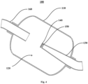
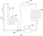
- the liquid reservoir 100 may include a drum body 110 and an air intake pipe 130.
- a gas-liquid separation chamber 120 is defined in the drum body 110.
- the air intake pipe 130 is used for connecting to an evaporating pipe 222 of an evaporator 220 of the refrigeration system, and extends into the gas-liquid separation chamber 120 from one end of the drum body 110, and the end of the air intake pipe 130 extending into the gas-liquid separation chamber 120 is provided with a baffle 140 opposite to a mouth of the air intake pipe 130, so that a mixture discharged from the air intake pipe 130 hits the baffle 140 and then is discharged into the gas-liquid separation chamber 120 from an interval between the baffle 140 and the air intake pipe 130.
- the mixture discharged from the air intake pipe 130 hits the baffle 140 so as to facilitate atomization of the mixture.
- the mixture discharged from the air intake pipe 130 is a gas-liquid mixture of a refrigerant and compressor oil
- the refrigerant liquid in the mixture is atomized after hitting the baffle 140
- the atomized liquid refrigerant can be gasified more quickly, so as to improve the gasification efficiency of the liquid refrigerant in the liquid reservoir 100, thereby improving the refrigeration efficiency of a refrigerator 10, and preventing the liquid refrigerant from entering the compressor 250 and causing adverse effects on the compressor 250.
- the compressor oil in the mixture is atomized after hitting the baffle 140, and the atomized compressor oil is more easily driven by an airflow to enter the compressor 250, so as to realize effective lubrication of the compressor 250 and improve the recovery efficiency of the oil.
- the liquid reservoir 100 may further include a plurality of support ribs 150.
- the plurality of support ribs 150 extend out from the end of the air intake pipe 130 extending into the gas-liquid separation chamber 120 along the extension direction of the air intake pipe 130.
- the baffle 140 is fixedly connected to the support ribs 150 to form the interval between the baffle 140 and the air intake pipe 130 by means of the plurality of support ribs 150.
- the baffle 140 is fixed in a position opposite to the mouth of the air intake pipe 130, so that the structural position of the baffle 140 is more stable. Under the impact of the airflow discharged from the air intake pipe 130, the baffle 140 can still be kept in a fixed position, thereby ensuring the effective atomization of the mixture discharged from the air intake pipe 130.
- the pipe diameter of the part of the air intake pipe 130 extending into the gas-liquid separation chamber 120 may gradually shrink with the increase of an extending length.
- the pipe diameter of the part of the air intake pipe 130 extending into the gas-liquid separation chamber 120 to gradually shrink with the increase of the extending length, that is, setting the air intake pipe 130 as a tapered pipe, when the mixture airflow discharged from the air intake pipe 130 hits the baffle, the impact force is greater, thereby improving the atomization effect of the mixture.
- the liquid reservoir 100 may further include an exhaust pipe 160.
- the exhaust pipe 160 extends into the gas-liquid separation chamber 120 from the other end of the drum body 110, and a set interval is formed between the end of the exhaust pipe 160 extending into the gas-liquid separation chamber 120 and the baffle 140.
- the exhaust pipe 160 conveys the refrigerant airflow entering the gas-liquid separation chamber 120 into the compressor 250, and the set interval is formed between the end of the exhaust pipe 160 extending into the gas-liquid separation chamber 120 and the baffle 140, so that a gaseous refrigerant can enter the exhaust pipe 160 conveniently.
- the length of the exhaust pipe 160 extending into the gas-liquid separation chamber 120 may be less than the length of the air intake pipe 130 extending into the gas-liquid separation chamber 120.
- the highest position of the liquid level of the liquid refrigerant in the liquid reservoir 100 is the position of the mouth of the air intake pipe 130. When there is excessive liquid refrigerant, the liquid refrigerant will return from the mouth of the air intake pipe 130. In other words, the longer the exhaust pipe 160 extending into the gas-liquid separation chamber 120 is, the more the liquid refrigerant can be stored in the liquid reservoir 100.
- the length of the exhaust pipe 160 extending into the gas-liquid separation chamber 120 is less than the length of the air intake pipe 130 extending into the gas-liquid separation chamber 120, a larger storage space for the liquid refrigerant can be ensured in the liquid reservoir 100.
- the refrigerant will naturally condense into liquid and accumulate at the bottom of the liquid reservoir 100, so as to store the excessive refrigerant.
- the dosage of the refrigerant for a cycle of the refrigeration system can be adjusted according to an ambient temperature.
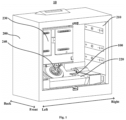
- the refrigerator 10 in this embodiment may further include a refrigerator body 200.
- the refrigerator body 200 is provided with a bottom liner 210, the bottom liner 210 defines a cooling chamber 212 and a storage space 211, and the cooling chamber 212 is arranged below the storage space 211.
- the evaporator 220 is entirely in a flat cuboid shape and is arranged at a front part of the cooling chamber 212.
- the liquid reservoir 100 is arranged behind the evaporator 220.
- a front side of the refrigerator body 200 is further provided with a door body for opening or closing the storage space 211. In order to show the internal structure of the refrigerator body 200, the door body is hidden in the drawing.
- the refrigerator 10 can be provided with a plurality of liners which can be divided into a freezing liner, a variable-temperature liner and a refrigerating liner according to functions, so as to define a plurality of storage compartments, such as a refrigerating compartment, a variable-temperature compartment and a freezing compartment.
- the bottom liner 210 refers to a liner at the bottom of the refrigerator 10.
- the bottom liner 210 at the bottom of the refrigerator 10 defines the storage space 211 and the cooling chamber 212 below the storage space 211 through a partition plate 213, wherein the storage space 211 defined by the bottom liner 210 may be a freezing compartment. Furthermore, a variable-temperature compartment defined by other liners of the refrigerator 10, and a refrigerating compartment above the variable-temperature compartment may further be arranged above the storage space 211.
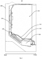
- the liquid reservoir 100 is arranged obliquely and upwards from the end with the air intake pipe 130.
- an angle of the obliquely arranged liquid reservoir 100 may be 10-35 degrees.
- the evaporator 220 is a finned evaporator.
- the finned evaporator may include: a group of fins, an evaporating pipe 222 and support end plates 221.
- the group of fins are arranged in parallel along the front-and-back direction of the refrigerator body 200.
- the evaporating pipe 222 penetrates through the fins.
- the support end plates 221 are arranged on both sides of the fins.
- An outlet of the evaporating pipe 222 is arranged behind the support end plate 221 on one side, and extends to the liquid reservoir 100 in an arc shape.
- the scheme of this embodiment uses the finned evaporator which is compact in structure, small in occupied area and high in heat transfer coefficient, thereby further improving the heat exchange efficiency of the evaporator 220, and ensuring the refrigeration and storage functions of the refrigerator 10.
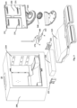
- the centrifugal fan 240 is obliquely arranged on a back side of the evaporator 220 entirely, and used for causing formation of a refrigerating airflow from air in front of the cooling chamber 212 discharged to the air supply duct through the evaporator 220, the distances from the center of an air inlet 241 of the centrifugal fan 240 to side plates on both sides of the bottom liner 210 are different, and the distance from the center of the air inlet 241 to a side wall of the bottom liner 210 close to the outlet of the evaporating pipe 222 is greater than the distance to a side wall of the bottom liner 210 away from the outlet of the evaporating pipe 222.
- the evaporator In a refrigerator with an evaporator mounted at the bottom in the prior art, the evaporator is horizontally arranged. When an airflow enters a cooling chamber, the airflow is easy to gather at the front end of the evaporator and cannot enter the evaporator smoothly for heat exchange.
- the evaporator 220 is obliquely arranged, so that the arrangement of components in the cooling chamber 212 is more reasonable.
- the analysis of an actual airflow field proves that the air cycle efficiency is higher, and the drainage is more smooth.
- the air duct cover plate 230 and the centrifugal fan 240 at the back of the bottom liner 210, the flow rate of refrigerating air flowing from the cooling chamber 212 into the storage space 211 is increased, so as to further ensure the refrigeration and storage effects of the refrigerator 10.
- one or a plurality of air supply outlets 231 may be arranged. In an embodiment as shown in FIG. 3 , four air supply outlets 231 are arranged on the air duct cover plate 230, so that the air supply is more uniform and smooth.
- the scheme of this embodiment uses the centrifugal fan 240 which is stable in operation and convenient in maintenance, and is sturdy and durable. Further, in this embodiment, the distance from the center of the air inlet 241 of the centrifugal fan 240 to a side wall of the bottom liner 210 close to an air return pipe 170 is greater than the distance to a side wall of the bottom liner 210 away from the air return pipe 170.
- the center of the air inlet 241 of an air supply fan is inclined to a left wall of the bottom liner 210, that is, the air supply fan is arranged in a position inclined to the left side of the bottom liner 210, so that the refrigerating air flows more smoothly from the air outlet of the fan to the air supply duct, so as to further improve the air supply efficiency of the fan.
- the mounting position of the centrifugal fan 240 is structurally optimized according to space requirements and refrigeration performance requirements, and the effect is verified by trial products.
- the baffle 140 in the liquid reservoir 100 in a position opposite to the mouth of the air intake pipe 130, the mixture discharged from the air intake pipe 130 hits the baffle 140 so as to facilitate atomization of the mixture.
- the refrigerant liquid in the mixture is atomized after hitting the baffle 140, and the atomized liquid refrigerant can be gasified more quickly, so as to improve the gasification efficiency of the liquid refrigerant in the liquid reservoir 100, thereby improving the refrigeration efficiency of the refrigerator 10, and preventing the liquid refrigerant from entering the compressor 250 and causing adverse effects on the compressor 250.
- the compressor oil in the mixture is atomized after hitting the baffle 140, and the atomized compressor oil is more easily driven by an airflow to enter the compressor 250, so as to realize effective lubrication of the compressor 250 and improve the recovery efficiency of the compressor oil.
- the design of an oil return hole at the bottom of the air intake pipe 130 is omitted, so as to prevent refrigerant bubbles from emitting through the oil return hole, thereby reducing the noise generated by the liquid reservoir 100.
Landscapes
- Engineering & Computer Science (AREA)
- General Engineering & Computer Science (AREA)
- Physics & Mathematics (AREA)
- Mechanical Engineering (AREA)
- Thermal Sciences (AREA)
- Chemical & Material Sciences (AREA)
- Combustion & Propulsion (AREA)
- Analytical Chemistry (AREA)
- Power Engineering (AREA)
- Cold Air Circulating Systems And Constructional Details In Refrigerators (AREA)
- Devices That Are Associated With Refrigeration Equipment (AREA)
- Jet Pumps And Other Pumps (AREA)
- Compressor (AREA)
- Removal Of Water From Condensation And Defrosting (AREA)
Claims (9)
- Réservoir de liquide (100) pour un système de réfrigération, comprenant :un corps de tambour (110), dans lequel est définie une chambre de séparation gaz-liquide (120) ; etun tuyau d'admission d'air (130), configuré pour être raccordé à un tuyau d'évaporation (222) d'un évaporateur (220) du système de réfrigération, et s'étendant dans la chambre de séparation gaz-liquide (120) depuis une extrémité du corps de tambour (110), l'extrémité du tuyau d'admission d'air (130) s'étendant dans la chambre de séparation gaz-liquide (120) étant munie d'un déflecteur (140) situé en face de l'embouchure du tuyau d'admission d'air (130), de sorte qu'un mélange sortant du tuyau d'admission d'air (130) heurte le déflecteur (140) puis est déchargé dans la chambre de séparation gaz-liquide (120) à partir d'un intervalle entre le déflecteur (140) et le tuyau d'admission d'air (130), caractérisé en ce quele diamètre du tuyau de la partie du tuyau d'admission d'air (130) s'étendant dans la chambre de séparation gaz-liquide (120) diminue progressivement à mesure que la longueur d'extension augmente.
- Réservoir de liquide (100) selon la revendication 1, comprenant en outre :
une pluralité de nervures de support (150), s'étendant à partir de l'extrémité du tuyau d'admission d'air (130) s'étendant dans la chambre de séparation gaz-liquide (120) le long de la direction d'extension du tuyau d'admission d'air (130), le déflecteur (140) étant fixé aux nervures de support (150) pour former l'intervalle entre le déflecteur (140) et le tuyau d'admission d'air (130) au moyen de la pluralité de nervures de support (150). - Réservoir de liquide (100) selon l'une quelconque des revendications 1 à 2, comprenant en outre :
un tuyau d'évacuation (160), s'étendant dans la chambre de séparation gaz-liquide (120) depuis l'autre extrémité du corps de tambour (110), un intervalle défini étant formé entre l'extrémité du tuyau d'évacuation (160) s'étendant dans la chambre de séparation gaz-liquide (120) et le déflecteur (140). - Réservoir de liquide (100) selon la revendication 3, dans lequel
la longueur du tuyau d'évacuation (160) s'étendant dans la chambre de séparation gaz-liquide (120) est inférieure à la longueur du tuyau d'admission d'air (130) s'étendant dans la chambre de séparation gaz-liquide (120). - Réfrigérateur (10), comprenant :un évaporateur (220) ; etle réservoir de liquide (100) selon l'une quelconque des revendications 1 à 4, raccordé à un tuyau d'évaporation (222) de l'évaporateur (220).
- Réfrigérateur (10) selon la revendication 5, comprenant en outre :un corps de réfrigérateur (200), muni d'une paroi inférieure, la paroi inférieure définissant une chambre de refroidissement et un espace de stockage, la chambre de refroidissement étant disposée sous l'espace de stockage ; dans lequell'évaporateur (220) est entièrement de forme cuboïde plate et est disposé à l'avant de la chambre de refroidissement ; etle réservoir de liquide (100) est disposé derrière l'évaporateur (220).
- Réfrigérateur (10) selon la revendication 6, dans lequel
le réservoir de liquide (100) est disposé en oblique et vers le haut par rapport à l'extrémité avec le tuyau d'admission d'air (130). - Réfrigérateur (10) selon la revendication 6 ou 7, dans lequel
l'évaporateur (220) est un évaporateur à ailettes (220), comprenant :un groupe d'ailettes, disposées parallèlement le long de la direction avant-arrière du corps de réfrigérateur (200) ;un tuyau d'évaporation (222), traversant les ailettes ; etdes plaques d'extrémité de support, disposées de part et d'autre des ailettes,dans lequel une sortie du tuyau d'évaporation (222) est disposée derrière la plaque d'extrémité de support d'un côté, et s'étend vers le réservoir de liquide (100) en forme d'arc. - Réfrigérateur (10) selon la revendication 8, dans lequel
l'évaporateur (220) est disposé obliquement le long de la direction de profondeur du réfrigérateur (10) par rapport à la direction horizontale, la direction oblique est vers le haut de l'avant vers l'arrière, et le réfrigérateur (10) comprend en outre :une plaque de recouvrement de conduit d'air, disposée à l'avant d'une paroi arrière de la paroi inférieure, et définissant un conduit d'alimentation en air avec la paroi arrière de la paroi inférieure, la plaque de recouvrement de conduit d'air étant munie d'au moins une sortie d'alimentation en air, et la sortie d'alimentation en air étant utilisée pour raccorder le conduit d'alimentation en air et l'espace de stockage ; etun ventilateur centrifuge, disposé obliquement sur une face arrière de l'évaporateur (220) dans son intégralité, et utilisé pour provoquer la formation d'un flux d'air réfrigérant à partir de l'air situé devant la chambre de refroidissement déchargé dans le conduit d'alimentation en air à travers l'évaporateur (220),les distances entre le centre d'une entrée d'air du ventilateur centrifuge et les plaques latérales des deux côtés de la paroi inférieure étant différentes, et la distance entre le centre de l'entrée d'air et une paroi latérale de la paroi inférieure proche de la sortie du tuyau d'évaporation (222) étant supérieure à la distance par rapport à une paroi latérale de la paroi inférieure éloignée de la sortie du tuyau d'évaporation (222).
Applications Claiming Priority (2)
| Application Number | Priority Date | Filing Date | Title |
|---|---|---|---|
| CN202021727434.9U CN214039059U (zh) | 2020-08-18 | 2020-08-18 | 用于制冷系统的储液器及冰箱 |
| PCT/CN2021/100126 WO2021223775A1 (fr) | 2020-08-18 | 2021-06-15 | Accumulateur de liquide et réfrigérateur utilisé pour un système de réfrigération |
Publications (4)
| Publication Number | Publication Date |
|---|---|
| EP4174406A1 EP4174406A1 (fr) | 2023-05-03 |
| EP4174406A4 EP4174406A4 (fr) | 2023-12-06 |
| EP4174406B1 true EP4174406B1 (fr) | 2024-07-24 |
| EP4174406C0 EP4174406C0 (fr) | 2024-07-24 |
Family
ID=77332319
Family Applications (1)
| Application Number | Title | Priority Date | Filing Date |
|---|---|---|---|
| EP21800418.2A Active EP4174406B1 (fr) | 2020-08-18 | 2021-06-15 | Accumulateur de liquide et réfrigérateur |
Country Status (8)
| Country | Link |
|---|---|
| US (1) | US12264857B2 (fr) |
| EP (1) | EP4174406B1 (fr) |
| JP (1) | JP2023538064A (fr) |
| CN (1) | CN214039059U (fr) |
| AU (1) | AU2021266850B2 (fr) |
| ES (1) | ES2986641T3 (fr) |
| NZ (1) | NZ796923A (fr) |
| WO (1) | WO2021223775A1 (fr) |
Families Citing this family (1)
| Publication number | Priority date | Publication date | Assignee | Title |
|---|---|---|---|---|
| CN114076464B (zh) * | 2020-08-18 | 2023-04-18 | 青岛海尔电冰箱有限公司 | 风冷冰箱 |
Family Cites Families (49)
| Publication number | Priority date | Publication date | Assignee | Title |
|---|---|---|---|---|
| US2450109A (en) * | 1946-08-28 | 1948-09-28 | Ed Friedrich Inc | Walk-in refrigerator cooled by a forced air circuit |
| US2994207A (en) * | 1959-02-25 | 1961-08-01 | Gen Motors Corp | Refrigerating apparatus with defrosting controls |
| US3027735A (en) * | 1960-01-25 | 1962-04-03 | Gen Motors Corp | Refrigerating apparatus |
| US3104533A (en) * | 1961-04-24 | 1963-09-24 | Gen Motors Corp | Refrigerating apparatus |
| US3111135A (en) * | 1962-09-14 | 1963-11-19 | Gen Electric | Improved accumulator for refrigerating system |
| US3252292A (en) * | 1964-02-10 | 1966-05-24 | Gen Motors Corp | Refrigerating apparatus |
| US3365118A (en) * | 1966-05-20 | 1968-01-23 | Gen Motors Corp | Circulating system |
| US3433031A (en) * | 1967-11-08 | 1969-03-18 | Whirlpool Co | Removable unitary refrigeration system |
| US3512374A (en) * | 1968-05-03 | 1970-05-19 | Parker Hannifin Corp | Suction accumulator for refrigeration systems |
| US3599442A (en) * | 1969-09-22 | 1971-08-17 | Gen Motors Corp | Unitary fan evaporator assembly |
| NO132106C (fr) | 1971-11-11 | 1975-09-17 | Sigurd Heien | |
| JPS506453U (fr) * | 1973-05-14 | 1975-01-23 | ||
| US3837177A (en) * | 1973-11-01 | 1974-09-24 | Refrigeration Research | Suction accumulator |
| JPS5192565A (en) | 1975-02-12 | 1976-08-13 | Parupuhaiekino shorihoho | |
| JPS5554234Y2 (fr) * | 1976-07-09 | 1980-12-15 | ||
| US4061482A (en) * | 1976-11-29 | 1977-12-06 | General Motors Corporation | Cooling coil and air distribution system defrost means |
| US4223538A (en) * | 1979-01-23 | 1980-09-23 | White Consolidated Industries, Inc. | Refrigerator compartment divider mounting |
| US4665716A (en) | 1984-09-21 | 1987-05-19 | Robert Cochran | Fluid flow control system |
| JPS6365271A (ja) | 1986-09-08 | 1988-03-23 | 松下冷機株式会社 | 冷蔵庫 |
| JPH0979707A (ja) * | 1995-09-11 | 1997-03-28 | Matsushita Refrig Co Ltd | アキュムレーター |
| JPH09250848A (ja) * | 1996-03-14 | 1997-09-22 | Mitsubishi Heavy Ind Ltd | 冷凍装置用横長アキュムレータ |
| US5727398A (en) * | 1996-07-25 | 1998-03-17 | Phillippe; Gary E. | Refrigerant agitation apparatus |
| US5706850A (en) * | 1996-11-19 | 1998-01-13 | Carrier Corporation | Oil diffuser |
| US6401470B1 (en) * | 2000-09-14 | 2002-06-11 | Xdx, Llc | Expansion device for vapor compression system |
| US6564575B1 (en) * | 2001-10-30 | 2003-05-20 | Visteon Global Technologies, Inc. | Accumulator with inlet port comprising a deflector |
| JP4009541B2 (ja) | 2003-02-06 | 2007-11-14 | 福島工業株式会社 | 冷蔵ショーケース |
| NL1024149C2 (nl) * | 2003-08-22 | 2005-02-23 | Flash Technologies N V | Inlaat- en verdeelinrichting. |
| DE102006017432B4 (de) * | 2006-04-06 | 2009-05-28 | Visteon Global Technologies Inc., Van Buren | Innerer Wärmeübertrager mit kalibriertem wendelförmigen Rippenrohr |
| KR20080050156A (ko) | 2006-12-01 | 2008-06-05 | 주식회사 대우일렉트로닉스 | 냉장고의 소음저감형 어큐뮬레이터 |
| JP4903119B2 (ja) * | 2007-06-25 | 2012-03-28 | 三菱電機株式会社 | 気液分離器とそれを搭載した空気調和機 |
| US9702602B2 (en) * | 2009-04-23 | 2017-07-11 | Gary E Phillippe | Method and apparatus for improving refrigeration and air conditioning efficiency |
| KR20110119553A (ko) | 2010-04-26 | 2011-11-02 | 니찌레이 고오교오 가부시끼가이샤 | 기액 분리 장치 및 기액 분리 장치를 구비한 냉동 장치 |
| US9261298B2 (en) * | 2010-07-23 | 2016-02-16 | Carrier Corporation | Ejector cycle refrigerant separator |
| CN102494465A (zh) | 2011-12-08 | 2012-06-13 | 合肥美的荣事达电冰箱有限公司 | 冰箱及用于冰箱的制冷装置 |
| CN204006834U (zh) | 2014-06-30 | 2014-12-10 | 浙江盾安机械有限公司 | 一种气液分离器 |
| JP5958621B2 (ja) * | 2014-08-22 | 2016-08-02 | ダイキン工業株式会社 | アキュームレータ |
| SG11201703070XA (en) * | 2014-10-14 | 2017-05-30 | Cass Khoo | Efficiency enhancing apparatus and methods for a heat exchange system |
| CN105605837A (zh) | 2015-12-14 | 2016-05-25 | 广东美的暖通设备有限公司 | 气液分离器及具有其的冷冻循环装置、制冷系统 |
| CN205843155U (zh) | 2016-07-27 | 2016-12-28 | 广东美的暖通设备有限公司 | 气液分离器和具有其的空调 |
| CN106052202A (zh) | 2016-08-15 | 2016-10-26 | 合肥太通制冷科技有限公司 | 一种三层双片形翅片蒸发器 |
| KR102604833B1 (ko) * | 2016-09-29 | 2023-11-22 | 엘지전자 주식회사 | 냉장고 |
| CN206247720U (zh) | 2016-10-20 | 2017-06-13 | 广东美的暖通设备有限公司 | 气液分离器和空调器 |
| CN108759196A (zh) | 2018-06-13 | 2018-11-06 | 苏州逸新和电子有限公司 | 一种过滤性能好的储液器 |
| CN208832796U (zh) | 2018-10-17 | 2019-05-07 | 浙江国祥股份有限公司 | 一种用于压缩机并联系统中的气液分离器 |
| JP7195875B2 (ja) | 2018-10-30 | 2022-12-26 | 東芝ライフスタイル株式会社 | 冷蔵庫 |
| JP7159856B2 (ja) | 2018-12-26 | 2022-10-25 | 株式会社デンソー | 空調装置 |
| CN210036003U (zh) * | 2019-04-26 | 2020-02-07 | 青岛海尔特种电冰箱有限公司 | 蒸发器与接水盘相匹配的冰箱 |
| CN110567214A (zh) * | 2019-09-12 | 2019-12-13 | 青岛海尔电冰箱有限公司 | 冰箱 |
| KR20230009088A (ko) * | 2021-07-08 | 2023-01-17 | 엘지전자 주식회사 | 저장고 |
-
2020
- 2020-08-18 CN CN202021727434.9U patent/CN214039059U/zh active Active
-
2021
- 2021-06-15 EP EP21800418.2A patent/EP4174406B1/fr active Active
- 2021-06-15 WO PCT/CN2021/100126 patent/WO2021223775A1/fr not_active Ceased
- 2021-06-15 NZ NZ796923A patent/NZ796923A/en unknown
- 2021-06-15 JP JP2023511901A patent/JP2023538064A/ja active Pending
- 2021-06-15 ES ES21800418T patent/ES2986641T3/es active Active
- 2021-06-15 US US18/042,067 patent/US12264857B2/en active Active
- 2021-06-15 AU AU2021266850A patent/AU2021266850B2/en active Active
Also Published As
| Publication number | Publication date |
|---|---|
| US12264857B2 (en) | 2025-04-01 |
| CN214039059U (zh) | 2021-08-24 |
| AU2021266850A1 (en) | 2023-03-02 |
| US20230304720A1 (en) | 2023-09-28 |
| EP4174406A4 (fr) | 2023-12-06 |
| JP2023538064A (ja) | 2023-09-06 |
| NZ796923A (en) | 2025-09-26 |
| AU2021266850B2 (en) | 2024-05-02 |
| EP4174406A1 (fr) | 2023-05-03 |
| ES2986641T3 (es) | 2024-11-12 |
| EP4174406C0 (fr) | 2024-07-24 |
| WO2021223775A1 (fr) | 2021-11-11 |
Similar Documents
| Publication | Publication Date | Title |
|---|---|---|
| CN1317538C (zh) | 冰箱 | |
| CN107621114B (zh) | 一种风冷冰箱 | |
| EP4174406B1 (fr) | Accumulateur de liquide et réfrigérateur | |
| CN102759227B (zh) | 一种制冷回路用降膜式蒸发器 | |
| CN201973964U (zh) | 一种具有气液分离功能的立式蒸发器 | |
| CN202692546U (zh) | 制冷回路用降膜式蒸发器 | |
| CN214949489U (zh) | 冷风机 | |
| JP2011231948A (ja) | 冷蔵庫 | |
| WO2022037718A1 (fr) | Réfrigérateur comportant un condenseur disposé dans un compartiment de compresseur | |
| WO2022037714A1 (fr) | Réfrigérateur permettant une réduction de perte de chaleur d'un conduit de retour d'air | |
| KR100819015B1 (ko) | 압축기 내장형 오일 분리기 | |
| CN217274916U (zh) | 制冷机组及具有其的制冷设备 | |
| CN111609623A (zh) | 具有l型冷凝器的冰箱 | |
| CN217764083U (zh) | 一种蒸发器顶置的制冷酒柜 | |
| CN210179777U (zh) | 一种便携式小型空调 | |
| KR100624025B1 (ko) | 공기조화장치용 어큐물레이터 | |
| CN114383367A (zh) | 制冷设备 | |
| CN217058036U (zh) | 回热器及包括其的制冷机组 | |
| CN223564522U (zh) | 制冷设备 | |
| CN219810074U (zh) | 制冷机组和制冷设备 | |
| CN222925789U (zh) | 油气分离装置及具有其的螺杆机组 | |
| JPS6240298Y2 (fr) | ||
| CN223258444U (zh) | 制冷设备 | |
| JP2008002733A (ja) | 冷蔵庫 | |
| CN220771423U (zh) | 制冷设备 |
Legal Events
| Date | Code | Title | Description |
|---|---|---|---|
| STAA | Information on the status of an ep patent application or granted ep patent |
Free format text: STATUS: THE INTERNATIONAL PUBLICATION HAS BEEN MADE |
|
| PUAI | Public reference made under article 153(3) epc to a published international application that has entered the european phase |
Free format text: ORIGINAL CODE: 0009012 |
|
| STAA | Information on the status of an ep patent application or granted ep patent |
Free format text: STATUS: REQUEST FOR EXAMINATION WAS MADE |
|
| 17P | Request for examination filed |
Effective date: 20230126 |
|
| AK | Designated contracting states |
Kind code of ref document: A1 Designated state(s): AL AT BE BG CH CY CZ DE DK EE ES FI FR GB GR HR HU IE IS IT LI LT LU LV MC MK MT NL NO PL PT RO RS SE SI SK SM TR |
|
| STAA | Information on the status of an ep patent application or granted ep patent |
Free format text: STATUS: EXAMINATION IS IN PROGRESS |
|
| DAV | Request for validation of the european patent (deleted) | ||
| DAX | Request for extension of the european patent (deleted) | ||
| A4 | Supplementary search report drawn up and despatched |
Effective date: 20231108 |
|
| RIC1 | Information provided on ipc code assigned before grant |
Ipc: F25B 43/00 20060101AFI20231102BHEP |
|
| 17Q | First examination report despatched |
Effective date: 20231120 |
|
| GRAP | Despatch of communication of intention to grant a patent |
Free format text: ORIGINAL CODE: EPIDOSNIGR1 |
|
| STAA | Information on the status of an ep patent application or granted ep patent |
Free format text: STATUS: GRANT OF PATENT IS INTENDED |
|
| INTG | Intention to grant announced |
Effective date: 20240318 |
|
| GRAS | Grant fee paid |
Free format text: ORIGINAL CODE: EPIDOSNIGR3 |
|
| GRAA | (expected) grant |
Free format text: ORIGINAL CODE: 0009210 |
|
| STAA | Information on the status of an ep patent application or granted ep patent |
Free format text: STATUS: THE PATENT HAS BEEN GRANTED |
|
| AK | Designated contracting states |
Kind code of ref document: B1 Designated state(s): AL AT BE BG CH CY CZ DE DK EE ES FI FR GB GR HR HU IE IS IT LI LT LU LV MC MK MT NL NO PL PT RO RS SE SI SK SM TR |
|
| REG | Reference to a national code |
Ref country code: GB Ref legal event code: FG4D |
|
| REG | Reference to a national code |
Ref country code: CH Ref legal event code: EP |
|
| REG | Reference to a national code |
Ref country code: DE Ref legal event code: R096 Ref document number: 602021016249 Country of ref document: DE |
|
| REG | Reference to a national code |
Ref country code: IE Ref legal event code: FG4D |
|
| U01 | Request for unitary effect filed |
Effective date: 20240820 |
|
| U07 | Unitary effect registered |
Designated state(s): AT BE BG DE DK EE FI FR IT LT LU LV MT NL PT SE SI Effective date: 20240828 |
|
| REG | Reference to a national code |
Ref country code: ES Ref legal event code: FG2A Ref document number: 2986641 Country of ref document: ES Kind code of ref document: T3 Effective date: 20241112 |
|
| PG25 | Lapsed in a contracting state [announced via postgrant information from national office to epo] |
Ref country code: NO Free format text: LAPSE BECAUSE OF FAILURE TO SUBMIT A TRANSLATION OF THE DESCRIPTION OR TO PAY THE FEE WITHIN THE PRESCRIBED TIME-LIMIT Effective date: 20241024 |
|
| PG25 | Lapsed in a contracting state [announced via postgrant information from national office to epo] |
Ref country code: GR Free format text: LAPSE BECAUSE OF FAILURE TO SUBMIT A TRANSLATION OF THE DESCRIPTION OR TO PAY THE FEE WITHIN THE PRESCRIBED TIME-LIMIT Effective date: 20241025 Ref country code: PL Free format text: LAPSE BECAUSE OF FAILURE TO SUBMIT A TRANSLATION OF THE DESCRIPTION OR TO PAY THE FEE WITHIN THE PRESCRIBED TIME-LIMIT Effective date: 20240724 |
|
| PG25 | Lapsed in a contracting state [announced via postgrant information from national office to epo] |
Ref country code: IS Free format text: LAPSE BECAUSE OF FAILURE TO SUBMIT A TRANSLATION OF THE DESCRIPTION OR TO PAY THE FEE WITHIN THE PRESCRIBED TIME-LIMIT Effective date: 20241124 |
|
| PG25 | Lapsed in a contracting state [announced via postgrant information from national office to epo] |
Ref country code: HR Free format text: LAPSE BECAUSE OF FAILURE TO SUBMIT A TRANSLATION OF THE DESCRIPTION OR TO PAY THE FEE WITHIN THE PRESCRIBED TIME-LIMIT Effective date: 20240724 |
|
| PG25 | Lapsed in a contracting state [announced via postgrant information from national office to epo] |
Ref country code: RS Free format text: LAPSE BECAUSE OF FAILURE TO SUBMIT A TRANSLATION OF THE DESCRIPTION OR TO PAY THE FEE WITHIN THE PRESCRIBED TIME-LIMIT Effective date: 20241024 |
|
| PG25 | Lapsed in a contracting state [announced via postgrant information from national office to epo] |
Ref country code: RS Free format text: LAPSE BECAUSE OF FAILURE TO SUBMIT A TRANSLATION OF THE DESCRIPTION OR TO PAY THE FEE WITHIN THE PRESCRIBED TIME-LIMIT Effective date: 20241024 Ref country code: PL Free format text: LAPSE BECAUSE OF FAILURE TO SUBMIT A TRANSLATION OF THE DESCRIPTION OR TO PAY THE FEE WITHIN THE PRESCRIBED TIME-LIMIT Effective date: 20240724 Ref country code: NO Free format text: LAPSE BECAUSE OF FAILURE TO SUBMIT A TRANSLATION OF THE DESCRIPTION OR TO PAY THE FEE WITHIN THE PRESCRIBED TIME-LIMIT Effective date: 20241024 Ref country code: IS Free format text: LAPSE BECAUSE OF FAILURE TO SUBMIT A TRANSLATION OF THE DESCRIPTION OR TO PAY THE FEE WITHIN THE PRESCRIBED TIME-LIMIT Effective date: 20241124 Ref country code: HR Free format text: LAPSE BECAUSE OF FAILURE TO SUBMIT A TRANSLATION OF THE DESCRIPTION OR TO PAY THE FEE WITHIN THE PRESCRIBED TIME-LIMIT Effective date: 20240724 Ref country code: GR Free format text: LAPSE BECAUSE OF FAILURE TO SUBMIT A TRANSLATION OF THE DESCRIPTION OR TO PAY THE FEE WITHIN THE PRESCRIBED TIME-LIMIT Effective date: 20241025 |
|
| PG25 | Lapsed in a contracting state [announced via postgrant information from national office to epo] |
Ref country code: SM Free format text: LAPSE BECAUSE OF FAILURE TO SUBMIT A TRANSLATION OF THE DESCRIPTION OR TO PAY THE FEE WITHIN THE PRESCRIBED TIME-LIMIT Effective date: 20240724 Ref country code: RO Free format text: LAPSE BECAUSE OF FAILURE TO SUBMIT A TRANSLATION OF THE DESCRIPTION OR TO PAY THE FEE WITHIN THE PRESCRIBED TIME-LIMIT Effective date: 20240724 |
|
| PG25 | Lapsed in a contracting state [announced via postgrant information from national office to epo] |
Ref country code: CZ Free format text: LAPSE BECAUSE OF FAILURE TO SUBMIT A TRANSLATION OF THE DESCRIPTION OR TO PAY THE FEE WITHIN THE PRESCRIBED TIME-LIMIT Effective date: 20240724 |
|
| PG25 | Lapsed in a contracting state [announced via postgrant information from national office to epo] |
Ref country code: SK Free format text: LAPSE BECAUSE OF FAILURE TO SUBMIT A TRANSLATION OF THE DESCRIPTION OR TO PAY THE FEE WITHIN THE PRESCRIBED TIME-LIMIT Effective date: 20240724 |
|
| PLBE | No opposition filed within time limit |
Free format text: ORIGINAL CODE: 0009261 |
|
| STAA | Information on the status of an ep patent application or granted ep patent |
Free format text: STATUS: NO OPPOSITION FILED WITHIN TIME LIMIT |
|
| 26N | No opposition filed |
Effective date: 20250425 |
|
| PGFP | Annual fee paid to national office [announced via postgrant information from national office to epo] |
Ref country code: GB Payment date: 20250625 Year of fee payment: 5 |
|
| U20 | Renewal fee for the european patent with unitary effect paid |
Year of fee payment: 5 Effective date: 20250630 |
|
| PGFP | Annual fee paid to national office [announced via postgrant information from national office to epo] |
Ref country code: ES Payment date: 20250710 Year of fee payment: 5 |
|
| REG | Reference to a national code |
Ref country code: CH Ref legal event code: H13 Free format text: ST27 STATUS EVENT CODE: U-0-0-H10-H13 (AS PROVIDED BY THE NATIONAL OFFICE) Effective date: 20260127 |
|
| PG25 | Lapsed in a contracting state [announced via postgrant information from national office to epo] |
Ref country code: MC Free format text: LAPSE BECAUSE OF FAILURE TO SUBMIT A TRANSLATION OF THE DESCRIPTION OR TO PAY THE FEE WITHIN THE PRESCRIBED TIME-LIMIT Effective date: 20240724 |
|
| PG25 | Lapsed in a contracting state [announced via postgrant information from national office to epo] |
Ref country code: IE Free format text: LAPSE BECAUSE OF NON-PAYMENT OF DUE FEES Effective date: 20250615 |
|
| PG25 | Lapsed in a contracting state [announced via postgrant information from national office to epo] |
Ref country code: CH Free format text: LAPSE BECAUSE OF NON-PAYMENT OF DUE FEES Effective date: 20250630 |