EP4174432A1 - Configuration de canal améliorée pour échangeur de chaleur pour refroidir une électronique de puissance - Google Patents
Configuration de canal améliorée pour échangeur de chaleur pour refroidir une électronique de puissance Download PDFInfo
- Publication number
- EP4174432A1 EP4174432A1 EP22204232.7A EP22204232A EP4174432A1 EP 4174432 A1 EP4174432 A1 EP 4174432A1 EP 22204232 A EP22204232 A EP 22204232A EP 4174432 A1 EP4174432 A1 EP 4174432A1
- Authority
- EP
- European Patent Office
- Prior art keywords
- fluid
- flow
- pathway
- heat exchanger
- power electronics
- Prior art date
- Legal status (The legal status is an assumption and is not a legal conclusion. Google has not performed a legal analysis and makes no representation as to the accuracy of the status listed.)
- Granted
Links
Images




Classifications
-
- F—MECHANICAL ENGINEERING; LIGHTING; HEATING; WEAPONS; BLASTING
- F28—HEAT EXCHANGE IN GENERAL
- F28F—DETAILS OF HEAT-EXCHANGE AND HEAT-TRANSFER APPARATUS, OF GENERAL APPLICATION
- F28F3/00—Plate-like or laminated elements; Assemblies of plate-like or laminated elements
- F28F3/12—Elements constructed in the shape of a hollow panel, e.g. with channels
-
- H—ELECTRICITY
- H05—ELECTRIC TECHNIQUES NOT OTHERWISE PROVIDED FOR
- H05K—PRINTED CIRCUITS; CASINGS OR CONSTRUCTIONAL DETAILS OF ELECTRIC APPARATUS; MANUFACTURE OF ASSEMBLAGES OF ELECTRICAL COMPONENTS
- H05K7/00—Constructional details common to different types of electric apparatus
- H05K7/20—Modifications to facilitate cooling, ventilating, or heating
- H05K7/2089—Modifications to facilitate cooling, ventilating, or heating for power electronics, e.g. for inverters for controlling motor
-
- F—MECHANICAL ENGINEERING; LIGHTING; HEATING; WEAPONS; BLASTING
- F28—HEAT EXCHANGE IN GENERAL
- F28F—DETAILS OF HEAT-EXCHANGE AND HEAT-TRANSFER APPARATUS, OF GENERAL APPLICATION
- F28F13/00—Arrangements for modifying heat-transfer, e.g. increasing, decreasing
- F28F13/06—Arrangements for modifying heat-transfer, e.g. increasing, decreasing by affecting the pattern of flow of the heat-exchange media
- F28F13/08—Arrangements for modifying heat-transfer, e.g. increasing, decreasing by affecting the pattern of flow of the heat-exchange media by varying the cross-section of the flow channels
-
- F—MECHANICAL ENGINEERING; LIGHTING; HEATING; WEAPONS; BLASTING
- F28—HEAT EXCHANGE IN GENERAL
- F28F—DETAILS OF HEAT-EXCHANGE AND HEAT-TRANSFER APPARATUS, OF GENERAL APPLICATION
- F28F13/00—Arrangements for modifying heat-transfer, e.g. increasing, decreasing
- F28F13/18—Arrangements for modifying heat-transfer, e.g. increasing, decreasing by applying coatings, e.g. radiation-absorbing, radiation-reflecting; by surface treatment, e.g. polishing
- F28F13/185—Heat-exchange surfaces provided with microstructures or with porous coatings
- F28F13/187—Heat-exchange surfaces provided with microstructures or with porous coatings especially adapted for evaporator surfaces or condenser surfaces, e.g. with nucleation sites
-
- F—MECHANICAL ENGINEERING; LIGHTING; HEATING; WEAPONS; BLASTING
- F28—HEAT EXCHANGE IN GENERAL
- F28F—DETAILS OF HEAT-EXCHANGE AND HEAT-TRANSFER APPARATUS, OF GENERAL APPLICATION
- F28F3/00—Plate-like or laminated elements; Assemblies of plate-like or laminated elements
- F28F3/02—Elements or assemblies thereof with means for increasing heat-transfer area, e.g. with fins, with recesses, with corrugations
- F28F3/025—Elements or assemblies thereof with means for increasing heat-transfer area, e.g. with fins, with recesses, with corrugations the means being corrugated, plate-like elements
-
- H—ELECTRICITY
- H05—ELECTRIC TECHNIQUES NOT OTHERWISE PROVIDED FOR
- H05K—PRINTED CIRCUITS; CASINGS OR CONSTRUCTIONAL DETAILS OF ELECTRIC APPARATUS; MANUFACTURE OF ASSEMBLAGES OF ELECTRICAL COMPONENTS
- H05K7/00—Constructional details common to different types of electric apparatus
- H05K7/20—Modifications to facilitate cooling, ventilating, or heating
- H05K7/20218—Modifications to facilitate cooling, ventilating, or heating using a liquid coolant without phase change in electronic enclosures
-
- H—ELECTRICITY
- H05—ELECTRIC TECHNIQUES NOT OTHERWISE PROVIDED FOR
- H05K—PRINTED CIRCUITS; CASINGS OR CONSTRUCTIONAL DETAILS OF ELECTRIC APPARATUS; MANUFACTURE OF ASSEMBLAGES OF ELECTRICAL COMPONENTS
- H05K7/00—Constructional details common to different types of electric apparatus
- H05K7/20—Modifications to facilitate cooling, ventilating, or heating
- H05K7/2029—Modifications to facilitate cooling, ventilating, or heating using a liquid coolant with phase change in electronic enclosures
- H05K7/20309—Evaporators
-
- H—ELECTRICITY
- H05—ELECTRIC TECHNIQUES NOT OTHERWISE PROVIDED FOR
- H05K—PRINTED CIRCUITS; CASINGS OR CONSTRUCTIONAL DETAILS OF ELECTRIC APPARATUS; MANUFACTURE OF ASSEMBLAGES OF ELECTRICAL COMPONENTS
- H05K7/00—Constructional details common to different types of electric apparatus
- H05K7/20—Modifications to facilitate cooling, ventilating, or heating
- H05K7/2089—Modifications to facilitate cooling, ventilating, or heating for power electronics, e.g. for inverters for controlling motor
- H05K7/20936—Liquid coolant with phase change
-
- F—MECHANICAL ENGINEERING; LIGHTING; HEATING; WEAPONS; BLASTING
- F28—HEAT EXCHANGE IN GENERAL
- F28D—HEAT-EXCHANGE APPARATUS, NOT PROVIDED FOR IN ANOTHER SUBCLASS, IN WHICH THE HEAT-EXCHANGE MEDIA DO NOT COME INTO DIRECT CONTACT
- F28D21/00—Heat-exchange apparatus not covered by any of the groups F28D1/00 - F28D20/00
- F28D2021/0019—Other heat exchangers for particular applications; Heat exchange systems not otherwise provided for
- F28D2021/0028—Other heat exchangers for particular applications; Heat exchange systems not otherwise provided for for cooling heat generating elements, e.g. for cooling electronic components or electric devices
- F28D2021/0029—Heat sinks
-
- F—MECHANICAL ENGINEERING; LIGHTING; HEATING; WEAPONS; BLASTING
- F28—HEAT EXCHANGE IN GENERAL
- F28D—HEAT-EXCHANGE APPARATUS, NOT PROVIDED FOR IN ANOTHER SUBCLASS, IN WHICH THE HEAT-EXCHANGE MEDIA DO NOT COME INTO DIRECT CONTACT
- F28D21/00—Heat-exchange apparatus not covered by any of the groups F28D1/00 - F28D20/00
- F28D2021/0019—Other heat exchangers for particular applications; Heat exchange systems not otherwise provided for
- F28D2021/0068—Other heat exchangers for particular applications; Heat exchange systems not otherwise provided for for refrigerant cycles
- F28D2021/0071—Evaporators
-
- F—MECHANICAL ENGINEERING; LIGHTING; HEATING; WEAPONS; BLASTING
- F28—HEAT EXCHANGE IN GENERAL
- F28F—DETAILS OF HEAT-EXCHANGE AND HEAT-TRANSFER APPARATUS, OF GENERAL APPLICATION
- F28F2255/00—Heat exchanger elements made of materials having special features or resulting from particular manufacturing processes
- F28F2255/12—Heat exchanger elements made of materials having special features or resulting from particular manufacturing processes expanded or perforated metal plate
Definitions
- the present invention pertains to the art of heat exchangers, and more particularly to heat exchangers for cooling power electronics.
- Power electronics devices such as motor drives generate waste heat during operation of the device. Additionally, when the power electronics devices heat up the operational efficiency of the devices can degrade adding to the amount of heat generated.
- a refrigeration system to drive for example, a compressor of the refrigeration system
- effective thermal integration of these devices can be an important aspect to the system's overall efficiency and reliability. Consequently, a goal of the system integrator is to maintain these components within a range of operating temperatures which will maximize the system efficiency. Accordingly, there remains a need in the art for heat exchangers configured to closely integrate with power electronic devices which can maintain optimal temperatures for these components under a variety of load conditions. Further, it is desired to increase capacity of such heat exchangers while reducing a pressure drop impact.
- a power electronics assembly includes one or more power electronics devices, and a heat exchanger to which the one or more power electronics devices are mounted.
- the heat exchanger includes an inlet manifold and an outlet manifold, and one or more fluid pathways extending between and connecting the inlet manifold and the outlet manifold, the heat exchanger configured to transfer thermal energy from the one or more power electronics devices into a flow of fluid passing through the one or more fluid pathways.
- the one or more fluid pathways include one or more internal enhancements and channel configurations to enhance thermal energy transfer by promoting boiling of the flow of fluid and to reduce the pressure drop in the pathways under a two-phase flow condition.
- the flow of fluid is a flow of liquid refrigerant diverted from a condenser of a heating, ventilation, and air conditioning (HVAC) system.
- HVAC heating, ventilation, and air conditioning
- the one or more fluid pathways may have a wavy shape along a length of the one or more fluid pathways.
- the one or more internal enhancements may include one or more inclined notches formed in the one or more fluid pathways.
- the (each) notch may be oriented at a notch angle of between 30 and 60 degrees relative to the flow of fluid through the one or more fluid pathways.
- a cross-sectional area of the one or more fluid pathways may increase along the flow direction of the flow of fluid from a pathway inlet to a pathway outlet.
- a heat exchanger outlet may have a larger cross-sectional area than a heat exchanger inlet.
- a wavy plate may be located in the (each) fluid pathway extending at least partially across the fluid pathway(s).
- the wavy plate may include a plurality of perforations along at least a partial length of the fluid pathway(s).
- One or more of a perforation number or a perforation size may increase from a fluid pathway inlet to a fluid pathway outlet by reducing the flow restrictions along the flow direction of the flow of fluid under the two-phase flow condition.
- the heat exchanger may be formed from a first plate including a first pathway portion of the one or more fluid pathways and a second plate including a second pathway portion of the one or more fluid pathways.
- the first pathway portion may be vertically offset from the second pathway portion.
- a method of cooling one or more power electronics devices includes securing the one or more power electronics devices to a heat exchanger, the heat exchanger including one or more fluid pathways.
- a flow of fluid is circulated through one or more fluid pathways to transfer thermal energy from the one or more power electronics to the flow of fluid passing through the one or more fluid pathways.
- the one or more fluid pathways include one or more internal enhancements and channel design to enhance thermal energy transfer by promoting boiling of the flow of fluid and to reduce the pressure drop in the pathways under two-phase flow condition.
- the flow of fluid is a flow of liquid refrigerant diverted from a condenser of a heating, ventilation, and air conditioning (HVAC) system.
- HVAC heating, ventilation, and air conditioning
- the one or more fluid pathways may have a wavy shape along a length of the one or more fluid pathways.
- the one or more internal enhancements may include one or more notches formed in the one or more fluid pathways, the one or more notches oriented at a notch angle of between 30 and 60 degrees relative to the flow of fluid through the one or more fluid pathways.
- a cross-sectional area of the one or more fluid pathways may increase from a pathway inlet to a pathway outlet.
- a heat exchanger outlet may have a greater cross-sectional area than a heat exchanger inlet.
- a wavy plate may be located in the (each) fluid pathway.
- the wavy plate may include a plurality of perforations.
- One or more of a perforation number or a perforation size may increase from a fluid pathway inlet to a fluid pathway outlet.
- the heat exchanger may be formed from a first plate including a first pathway portion of the one or more fluid pathways and a second plate including a second pathway portion of the one or more fluid pathways.
- the first pathway portion may be vertically offset from the second pathway portion.
- the power electronics assembly 10 includes one or more power electronics devices 12 mounted to a heat exchanger 14 utilized to reject and dissipate thermal energy generated by the power electronics devices 12 during operation.
- the power electronics devices 12 include a variable frequency drive (VFD) operably connected to a compressor 16 of a heating, ventilation, and air conditioning (HVAC) system 18.
- VFD variable frequency drive
- HVAC heating, ventilation, and air conditioning
- the HVAC system 18 includes, for example, a vapor compression circuit 100 including the compressor 16, a condenser 102, an expansion device 104 and an evaporator 106 arranged in series and having a volume of refrigerant flowing therethrough.
- the power electronics assembly 10 is connected to the vapor compression circuit 100 such that a portion of the flow of liquid refrigerant exiting the condenser 102 is diverted through the heat exchanger 14, bypassing the expansion device 104 and is directed from the heat exchanger 14 to the evaporator 106.
- the liquid refrigerant from the condenser 102 absorbs thermal energy generated by the power electronics devices 12. This thermal energy generated by the power electronics devices 12 may cause the refrigerant passing through the heat exchanger 14 to boil, changing phase of the refrigerant from liquid to vapor inside the heat exchanger 14.
- the heat exchanger 14 includes a plurality of enclosed fluid pathways 20 extending therethrough, enabling a flow of fluid 22 such as, for example, refrigerant, glycol, or water to flow therein.
- the fluid pathways 20 extend between a heat exchanger inlet 26 through which the flow of fluid 22 enters the heat exchanger 14, and a heat exchanger outlet 24 through which the flow of fluid 22 exits the heat exchanger 14.
- the heat exchanger outlet 24 is oriented vertically upwardly as shown to prevent vapor lock in the heat exchanger 14 flowpath under boiling condition.
- the heat exchanger inlet 26 is connected to the fluid pathways 20 via an inlet manifold 30 to distribute the flow of fluid 22 to the fluid pathways 20, and similarly the heat exchanger outlet 24 is connected to the fluid pathways 20 via an outlet manifold 28.
- orifices 110 Located downstream of the inlet manifold 30, orifices 110 of different diameters, increasing with increasing distance from the heat exchanger inlet 26 are provided to distribute the flow of fluid 22 from the inlet manifold 30 equally among all of the fluid pathways 20.
- the enhancement features described in the following text will be in the fluid pathways 20 downstream of the respective orifices 110.
- the heat exchanger 14 is formed from a metal material, such as aluminum, aluminum alloy, steel, steel alloy, copper, copper alloy, or the like, and referring again to FIG. 1 , may be formed from two or more plates 32, 34 abutting one another along a side and joined using any suitable means such as brazing, welding, clamping, compressing, bolting, and the like.
- the plates 32, 34 may each include a portion of the fluid pathways 20, the inlet manifold 30, the outlet manifold 28, the heat exchanger inlet 26 and/or the heat exchanger outlet 24 formed therein.
- the mating surfaces of the plates 32, 34 can be configured to correspond to one another, e.g., to fit together and seal the fluid circuit therebetween.
- the mating surfaces of the plates 32, 34 can include precision surfaces formed from a process having highly accurate and precise dimensional control, such as through computer numerical control (CNC) machining process and/or net shape, or near net shape manufacturing process.
- CNC computer numerical control
- a sealing material can be disposed between the plates 32, 34 to aide in preventing leakage from the fluid circuit.
- the flow of fluid 22 enters the heat exchanger 14 at the heat exchanger inlet 26 and is distributed to the fluid pathways 20 via the inlet manifold 30.
- the heat exchanger 14 conducts thermal energy from the power electronics devices 12 and thermal energy is exchanged with the flow of fluid 22 flowing through the fluid pathways 20, resulting in cooling of the power electronics devices 12.
- the vapor flow of fluid 22 is then collected at the outlet manifold 28 and exits the heat exchanger 14 at the heat exchanger outlet 24.
- the heat exchanger 14 described herein includes one or more features, as will be described below, to improve heat transfer capacity of the heat exchanger 14 while reducing a pressure drop penalty of operation of the heat exchanger 14. While the features are described independently below, one skilled in the art will readily appreciate that the features may be incorporated into the heat exchanger 14 either independently or in combinations of two or more of the features to promote nucleate boiling heat transfer and to reduce pressure drop under two-phase flow condition while quality increases along the flow direction.
- the flow of fluid 22 provided to the heat exchanger 14 is diverted from the condenser 102 and in some embodiments enters the heat exchanger 14 in a liquid phase with 0% vapor quality or up to 20% vapor quality.
- the presently disclosed heat exchanger 14 may be operated to ensure the vapor quality of the flow of fluid 22 exiting the heat exchanger 14 has a vapor quality of from about 25% to about 80%, or in another embodiment from about 40% to about 60%, or in yet another embodiment from about 45% to about 55%, or about 50%.
- the vapor quality change happens as the heat from power electronics devices 12 is absorbed by the flow and used for phase change of the liquid refrigerant to vapor while travelling from the heat exchanger inlet 26 to the heat exchanger outlet 24.
- the fluid pathways 20 of the heat exchanger 14 may be formed to increase heat transfer area along a heat exchanger length 32.
- the fluid pathways 20 may have a wavy shape along the heat exchanger length.
- the wavy shape is a sinusoidal shape, but it is to be appreciated that other shapes may be utilized.
- a peak-to-peak wavelength 34 of the fluid pathway 20 is in the range of 100 millimeters to 300 millimeters, while an amplitude 36 of the wave shape is in the range of 0.5 to 1.5 times a pathway diameter 38 of the fluid pathway 20.
- the wave shape may extend along an entire length of the fluid pathway 20, while in some embodiments the wave shape may extend along only a portion of the length of the fluid pathway 20.
- the fluid pathways 20 may have heat transfer enhancement features formed therein.
- the fluid pathways 20 may have notches 40 or grooves formed in a pathway wall 42 at a notch angle 44 relative to the direction of fluid flow through the fluid pathway 20.
- the notches 40 aid in spreading the flow of fluid 22 along the Notches will help spreading the liquid along the pathway wall 42 thereby keeping the pathway wall 42 wet, and promoting nucleate boiling at the pathway wall 42. Further, the notches 40 promote turbulence in the flow of fluid 22 to increase mixing of the flow of fluid 22.
- the notches 40 extend unbroken around an entire circumference of the fluid pathway 20, while in other embodiments the notches 40 are segmented and extend only a selected circumferential angle around the fluid pathway 20.
- a notch depth 60 is in the range of 300-700 micron.
- a notch width 62 may be in the range of 200-2000 micron, while a notch pitch 64 between adjacent notches 40 may be in the range of 400-5000 microns.
- the notch angle 44 is between 30 degrees and 60 degrees. While in the embodiments illustrated herein the notches 40 have a rectangular shape, other shapes such a triangular to semicircular, for example, may be utilized.
- the fluid pathways 20 may have an increasing cross-sectional area, such that an outlet cross-sectional area 46 at the outlet manifold 30 is greater than an inlet cross-sectional area 48 at the inlet manifold 28.
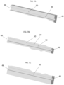
- the change in cross-sectional area may be achieved by one or more steps 50 formed in the fluid pathway as in FIG. 7a and 7b , or alternatively may be a gradual, continuous increase in area as illustrated in FIG. 7c .
- the area change will help in reducing the pressure drop in the fluid pathways 20 as volume of vapor flow under two-phase condition increases from inlet to outlet.
- the outlet manifold 28 may be sized relative to the inlet manifold 30 to account for the increased vapor volume at the outlet manifold 28.
- the outlet manifold 28 may have a larger hydraulic diameter 52 than the inlet manifold hydraulic diameter 54.
- the heat exchanger outlet 24 may be sized to have a larger flow area than the heat exchanger inlet 26 to similarly account for the increased vapor volume under two-phase condition at the heat exchanger outlet 24 to reduce the pressure drop along the heat exchanger 26.
- a wavy plate 66 is disposed in the fluid pathway 20 extending partially across a pathway height 68.
- the wavy plate 66 extends between 25 and 75 percent across the pathway height 68.
- the wavy plate 66 has a plate thickness 70 between 0.1-0.5 millimeters.
- the wavy plate 66 may have a plate wavelength 72 between 50-200 millimeters, and/or a plate amplitude 74 between about 10 percent and 40 percent of the pathway height 68 i.e covering 20 to 80% of the pathway height.
- the wavy plate 66 increases turbulence and mixing of the flow of fluid 22 in the fluid pathway 20.
- the wavy plate 70 can either cover the partial length of the pathway 20 or the entire length of the pathway 20.
- the wavy plate 66 can be installed perpendicular to face 68 (vertical face) or it can be inclined at an angle 45-90 deg. This would help draining of the liquid towards the heated wall, so it will keep the wall wet and enhance nucleate boiling. Also, the meniscus formed at the junction of the waveplate and trough of the wave would assist in thin film evaporation.
- the wavy plate 66 extends entirely across the pathway height 68 and includes a plurality of perforations 76 formed therein.
- the perforations 76 are between 0.5 millimeters and 2 millimeters in diameter.
- the wavy plate 66 may be configured such that an open area for the flow of fluid 22 through wavy plate 66 increases along the flow direction of the flow of fluid 22 along the fluid pathway 20. This may be accomplished by increasing the number of perforations 76 and/or increasing the size of the perforations 76. The area change will help in reducing the pressure drop in the fluid pathway 20 as volume of vapor flow increases from inlet to outlet under two-phase boiling condition. More (i.e.
- an increased number of) perforations 76 also results in higher heat transfer area and improves the heat transfer performance.
- the number of perforations 76 near the entrance of the fluid pathway 20 can be increased and relative to that flow area must increase along the length.
- the wavy plate 66 can either cover the partial length of the fluid pathway 20 or the entire length of the fluid pathway 20. This would help reduce the pressure drop resistance.
- each plate 32, 34 has a portion of the fluid pathway 20 formed therein.
- a first pathway portion 78 formed in the first plate 32 may be offset in a vertical direction relative to a second pathway portion 80 formed in the second plate 34.
- the offset of the first pathway portion 78 and the second pathway portion 80 may be between 20 percent and 70 percent of the pathway height 68, and may be biased such that the first plate 32 has the power electronics devices 12 mounted thereto, and the first pathway portions 78 are vertically lower than the second pathway portions 80. This arrangement aids in directing the flow of liquid into the first pathway portions 78 closer to the power electronics devices 12 as shown in FIG.
- the fluid pathways 20 may be provided with additional two or more corners as shown in FIG. 14 to promote thin film evaporation when the flow will be transitioned to annular flow.
- the corners of the fluid pathways 20 will have a liquid meniscus that will promote thin film evaporation.
- the enhanced features of the heat exchanger 14 as disclosed herein promote convective flow boiling for high heat transfer rate, reduced pressure drop and improved compactness of the heat exchanger 14.
Landscapes
- Engineering & Computer Science (AREA)
- Microelectronics & Electronic Packaging (AREA)
- Physics & Mathematics (AREA)
- Thermal Sciences (AREA)
- Mechanical Engineering (AREA)
- General Engineering & Computer Science (AREA)
- Chemical & Material Sciences (AREA)
- Crystallography & Structural Chemistry (AREA)
- Heat-Exchange Devices With Radiators And Conduit Assemblies (AREA)
Applications Claiming Priority (1)
| Application Number | Priority Date | Filing Date | Title |
|---|---|---|---|
| US202163272298P | 2021-10-27 | 2021-10-27 |
Publications (2)
| Publication Number | Publication Date |
|---|---|
| EP4174432A1 true EP4174432A1 (fr) | 2023-05-03 |
| EP4174432B1 EP4174432B1 (fr) | 2025-04-30 |
Family
ID=84044769
Family Applications (1)
| Application Number | Title | Priority Date | Filing Date |
|---|---|---|---|
| EP22204232.7A Active EP4174432B1 (fr) | 2021-10-27 | 2022-10-27 | Configuration de canal améliorée pour échangeur de chaleur pour refroidir une électronique de puissance |
Country Status (3)
| Country | Link |
|---|---|
| US (1) | US12593427B2 (fr) |
| EP (1) | EP4174432B1 (fr) |
| CN (1) | CN116033706A (fr) |
Citations (8)
| Publication number | Priority date | Publication date | Assignee | Title |
|---|---|---|---|---|
| US5002123A (en) * | 1989-04-20 | 1991-03-26 | Microelectronics And Computer Technology Corporation | Low pressure high heat transfer fluid heat exchanger |
| US20090302458A1 (en) * | 2005-06-27 | 2009-12-10 | Hidehito Kubo | Heat Sink For Power Module |
| US20110079376A1 (en) * | 2009-10-03 | 2011-04-07 | Wolverine Tube, Inc. | Cold plate with pins |
| US20130056176A1 (en) * | 2011-08-26 | 2013-03-07 | Mikros Manufacturing, Inc. | Heat Exchanger with Controlled Coefficient of Thermal Expansion |
| US20140158324A1 (en) * | 2012-12-07 | 2014-06-12 | Mitsubishi Electric Corporation | Cooling apparatus |
| CN104465562A (zh) * | 2014-12-24 | 2015-03-25 | 西安电子科技大学 | 一种链式交错型微通道结构 |
| US20170064866A1 (en) * | 2015-08-28 | 2017-03-02 | National Chiao Tung University | Heat conducting module |
| CN108225079A (zh) * | 2017-12-26 | 2018-06-29 | 华北电力大学 | 一种顶部联通的非均匀润湿性硅基微通道相变换热器 |
Family Cites Families (34)
| Publication number | Priority date | Publication date | Assignee | Title |
|---|---|---|---|---|
| US3273599A (en) * | 1966-09-20 | Internally finned condenser tube | ||
| US3457990A (en) * | 1967-07-26 | 1969-07-29 | Union Carbide Corp | Multiple passage heat exchanger utilizing nucleate boiling |
| US4044797A (en) * | 1974-11-25 | 1977-08-30 | Hitachi, Ltd. | Heat transfer pipe |
| US4118944A (en) * | 1977-06-29 | 1978-10-10 | Carrier Corporation | High performance heat exchanger |
| US4314742A (en) * | 1980-06-02 | 1982-02-09 | United Technologies Corporation | High performance cooled laser mirror |
| JPS60142195A (ja) * | 1983-12-28 | 1985-07-27 | Hitachi Cable Ltd | 内面溝付伝熱管 |
| DE68912636D1 (de) * | 1988-04-13 | 1994-03-10 | Mitsubishi Aluminium | Wärmeaustauscherkern. |
| US5031693A (en) * | 1990-10-31 | 1991-07-16 | Sundstrand Corporation | Jet impingement plate fin heat exchanger |
| US5465782A (en) | 1994-06-13 | 1995-11-14 | Industrial Technology Research Institute | High-efficiency isothermal heat pipe |
| US20020096314A1 (en) * | 2001-01-25 | 2002-07-25 | Carrier Corporation | High performance micro-rib tube |
| US20030192669A1 (en) * | 2002-04-10 | 2003-10-16 | Memfuel International Corporation | Micro-loop heat pipe |
| WO2004042306A2 (fr) * | 2002-11-01 | 2004-05-21 | Cooligy, Inc. | Procede et appareil d'obtention de l'uniformite thermique et de refroidissement de point chaud dans un dispositif de production de chaleur |
| CN1288752C (zh) | 2004-02-06 | 2006-12-06 | 中国科学院广州能源研究所 | 硅基微通道热交换器 |
| US20070119572A1 (en) * | 2005-11-30 | 2007-05-31 | Raytheon Company | System and Method for Boiling Heat Transfer Using Self-Induced Coolant Transport and Impingements |
| US8453719B2 (en) * | 2006-08-28 | 2013-06-04 | Dana Canada Corporation | Heat transfer surfaces with flanged apertures |
| US20090260789A1 (en) * | 2008-04-21 | 2009-10-22 | Dana Canada Corporation | Heat exchanger with expanded metal turbulizer |
| WO2010060342A1 (fr) | 2008-11-03 | 2010-06-03 | Zhao Yaohua | Caloduc doté d’un réseau de tubes à micropores, son procédé de fabrication et système d’échange de chaleur |
| US20100147492A1 (en) * | 2008-12-10 | 2010-06-17 | Ronald David Conry | IGBT cooling method |
| US8081461B2 (en) * | 2009-06-25 | 2011-12-20 | International Business Machines Corporation | Cooling apparatus with thermally conductive porous material and jet impingement nozzle(s) extending therein |
| WO2011077720A1 (fr) * | 2009-12-22 | 2011-06-30 | ダイキン工業株式会社 | Dispositif de refrigeration |
| KR20120135771A (ko) * | 2011-06-07 | 2012-12-17 | 엘지전자 주식회사 | 공기 조화기의 실외기 및 그 제어방법 |
| US20140145107A1 (en) * | 2012-11-28 | 2014-05-29 | Massachusetts Institute Of Technology | Heat Exchangers Using Metallic Foams on Fins |
| CN203349670U (zh) * | 2013-07-08 | 2013-12-18 | 郑州大学 | 一种微通道换热器 |
| DE112015000600T5 (de) * | 2014-01-30 | 2016-11-10 | Dana Canada Corporation | Wärmetauscher mit abgestimmtem Durchfluss zum Batterie-Thermomanagement |
| TWI590571B (zh) * | 2014-12-08 | 2017-07-01 | 強生控制科技公司 | 可變速驅動器系統及冷卻系統 |
| US10462935B2 (en) * | 2015-06-23 | 2019-10-29 | Google Llc | Cooling electronic devices in a data center |
| US10390466B2 (en) * | 2016-07-29 | 2019-08-20 | Schlumberger Technology Corporation | External structure heat sink |
| WO2018039532A1 (fr) * | 2016-08-26 | 2018-03-01 | Carrier Corporation | Distributeur de fluide frigorigène pour évaporateur a film tombant |
| US10136550B2 (en) * | 2016-09-30 | 2018-11-20 | International Business Machines Corporation | Cold plate device for a two-phase cooling system |
| US10371461B2 (en) * | 2016-10-11 | 2019-08-06 | International Business Machines Corporation | Multi-layered counterflow expanding microchannel cooling architecture and system thereof |
| JP6636996B2 (ja) * | 2017-07-11 | 2020-01-29 | ファナック株式会社 | Ldモジュール冷却装置及びレーザ装置 |
| US20200221611A1 (en) * | 2017-11-30 | 2020-07-09 | Mitsubishi Electric Corporation | Power conversion device and air-conditioning apparatus |
| DK3742097T3 (da) * | 2019-05-23 | 2023-10-09 | Ovh | Vandblokanordning |
| WO2021166204A2 (fr) * | 2020-02-21 | 2021-08-26 | 三菱電機株式会社 | Dispositif de climatisation |
-
2022
- 2022-10-20 US US18/048,237 patent/US12593427B2/en active Active
- 2022-10-26 CN CN202211317000.5A patent/CN116033706A/zh active Pending
- 2022-10-27 EP EP22204232.7A patent/EP4174432B1/fr active Active
Patent Citations (8)
| Publication number | Priority date | Publication date | Assignee | Title |
|---|---|---|---|---|
| US5002123A (en) * | 1989-04-20 | 1991-03-26 | Microelectronics And Computer Technology Corporation | Low pressure high heat transfer fluid heat exchanger |
| US20090302458A1 (en) * | 2005-06-27 | 2009-12-10 | Hidehito Kubo | Heat Sink For Power Module |
| US20110079376A1 (en) * | 2009-10-03 | 2011-04-07 | Wolverine Tube, Inc. | Cold plate with pins |
| US20130056176A1 (en) * | 2011-08-26 | 2013-03-07 | Mikros Manufacturing, Inc. | Heat Exchanger with Controlled Coefficient of Thermal Expansion |
| US20140158324A1 (en) * | 2012-12-07 | 2014-06-12 | Mitsubishi Electric Corporation | Cooling apparatus |
| CN104465562A (zh) * | 2014-12-24 | 2015-03-25 | 西安电子科技大学 | 一种链式交错型微通道结构 |
| US20170064866A1 (en) * | 2015-08-28 | 2017-03-02 | National Chiao Tung University | Heat conducting module |
| CN108225079A (zh) * | 2017-12-26 | 2018-06-29 | 华北电力大学 | 一种顶部联通的非均匀润湿性硅基微通道相变换热器 |
Also Published As
| Publication number | Publication date |
|---|---|
| US12593427B2 (en) | 2026-03-31 |
| US20230126158A1 (en) | 2023-04-27 |
| CN116033706A (zh) | 2023-04-28 |
| EP4174432B1 (fr) | 2025-04-30 |
Similar Documents
| Publication | Publication Date | Title |
|---|---|---|
| CN102084203B (zh) | 热交换器 | |
| US8061416B2 (en) | Heat exchanger and method for the production thereof | |
| WO2022166224A1 (fr) | Échangeur de chaleur, boîtier de commande électrique et système de climatisation | |
| CN116887567A (zh) | 电控盒及空调系统 | |
| US20210404750A1 (en) | Integrated hybrid compact fluid heat exchanger | |
| CN107560472B (zh) | 包括用于分配液体/气体混合物的装置的热交换器 | |
| WO2008024066A1 (fr) | Échangeur de chaleur à plaques et installation d'échangeur de chaleur | |
| JP3911604B2 (ja) | 熱交換器および冷凍サイクル | |
| EP4174432A1 (fr) | Configuration de canal améliorée pour échangeur de chaleur pour refroidir une électronique de puissance | |
| EP4175436A1 (fr) | Dissipateur thermique refroidi par réfrigérant pour modules électroniques de puissance | |
| US12408311B2 (en) | Combined liquid and air cooled power electronics assembly | |
| CN114909831B (zh) | 换热器、电控盒及空调系统 | |
| US20230128951A1 (en) | Heat exchanger for power electronics | |
| JP2001304719A (ja) | モジュール形多重流路扁平管蒸発器 | |
| CN218920815U (zh) | 散热器及变频空调系统 | |
| EP4093169B1 (fr) | Échangeur thermique pour l'électronique de puissance | |
| EP4175435A1 (fr) | Dissipateur thermique refroidi par liquide de tube à micro-ailettes mécaniquement expansé | |
| CN102022869A (zh) | 扁管换热器结构 | |
| RU2823845C2 (ru) | Теплообменник, электрический блок управления и система кондиционирования воздуха | |
| RU2821677C2 (ru) | Теплообменник и способ его изготовления, электрический блок управления и система кондиционирования воздуха | |
| RU2824964C2 (ru) | Система кондиционирования воздуха | |
| US20050006072A1 (en) | Heat exchanger | |
| US20240414881A1 (en) | Cooling system for power electronics | |
| US20250085061A1 (en) | Plate heat exchanger for phase separation | |
| US20250085022A1 (en) | Plate heat exchanger with 3d circulation of fluid |
Legal Events
| Date | Code | Title | Description |
|---|---|---|---|
| PUAI | Public reference made under article 153(3) epc to a published international application that has entered the european phase |
Free format text: ORIGINAL CODE: 0009012 |
|
| STAA | Information on the status of an ep patent application or granted ep patent |
Free format text: STATUS: THE APPLICATION HAS BEEN PUBLISHED |
|
| AK | Designated contracting states |
Kind code of ref document: A1 Designated state(s): AL AT BE BG CH CY CZ DE DK EE ES FI FR GB GR HR HU IE IS IT LI LT LU LV MC ME MK MT NL NO PL PT RO RS SE SI SK SM TR |
|
| P01 | Opt-out of the competence of the unified patent court (upc) registered |
Effective date: 20230527 |
|
| STAA | Information on the status of an ep patent application or granted ep patent |
Free format text: STATUS: REQUEST FOR EXAMINATION WAS MADE |
|
| 17P | Request for examination filed |
Effective date: 20231103 |
|
| RBV | Designated contracting states (corrected) |
Designated state(s): AL AT BE BG CH CY CZ DE DK EE ES FI FR GB GR HR HU IE IS IT LI LT LU LV MC ME MK MT NL NO PL PT RO RS SE SI SK SM TR |
|
| STAA | Information on the status of an ep patent application or granted ep patent |
Free format text: STATUS: EXAMINATION IS IN PROGRESS |
|
| 17Q | First examination report despatched |
Effective date: 20240314 |
|
| GRAP | Despatch of communication of intention to grant a patent |
Free format text: ORIGINAL CODE: EPIDOSNIGR1 |
|
| STAA | Information on the status of an ep patent application or granted ep patent |
Free format text: STATUS: GRANT OF PATENT IS INTENDED |
|
| INTG | Intention to grant announced |
Effective date: 20241125 |
|
| GRAS | Grant fee paid |
Free format text: ORIGINAL CODE: EPIDOSNIGR3 |
|
| GRAA | (expected) grant |
Free format text: ORIGINAL CODE: 0009210 |
|
| STAA | Information on the status of an ep patent application or granted ep patent |
Free format text: STATUS: THE PATENT HAS BEEN GRANTED |
|
| AK | Designated contracting states |
Kind code of ref document: B1 Designated state(s): AL AT BE BG CH CY CZ DE DK EE ES FI FR GB GR HR HU IE IS IT LI LT LU LV MC ME MK MT NL NO PL PT RO RS SE SI SK SM TR |
|
| REG | Reference to a national code |
Ref country code: CH Ref legal event code: EP Ref country code: GB Ref legal event code: FG4D |
|
| REG | Reference to a national code |
Ref country code: IE Ref legal event code: FG4D |
|
| REG | Reference to a national code |
Ref country code: DE Ref legal event code: R096 Ref document number: 602022013846 Country of ref document: DE |
|
| REG | Reference to a national code |
Ref country code: NL Ref legal event code: FP |
|
| REG | Reference to a national code |
Ref country code: AT Ref legal event code: MK05 Ref document number: 1790359 Country of ref document: AT Kind code of ref document: T Effective date: 20250430 |
|
| PG25 | Lapsed in a contracting state [announced via postgrant information from national office to epo] |
Ref country code: PT Free format text: LAPSE BECAUSE OF FAILURE TO SUBMIT A TRANSLATION OF THE DESCRIPTION OR TO PAY THE FEE WITHIN THE PRESCRIBED TIME-LIMIT Effective date: 20250901 Ref country code: ES Free format text: LAPSE BECAUSE OF FAILURE TO SUBMIT A TRANSLATION OF THE DESCRIPTION OR TO PAY THE FEE WITHIN THE PRESCRIBED TIME-LIMIT Effective date: 20250430 Ref country code: FI Free format text: LAPSE BECAUSE OF FAILURE TO SUBMIT A TRANSLATION OF THE DESCRIPTION OR TO PAY THE FEE WITHIN THE PRESCRIBED TIME-LIMIT Effective date: 20250430 |
|
| REG | Reference to a national code |
Ref country code: LT Ref legal event code: MG9D |
|
| PG25 | Lapsed in a contracting state [announced via postgrant information from national office to epo] |
Ref country code: NO Free format text: LAPSE BECAUSE OF FAILURE TO SUBMIT A TRANSLATION OF THE DESCRIPTION OR TO PAY THE FEE WITHIN THE PRESCRIBED TIME-LIMIT Effective date: 20250730 Ref country code: GR Free format text: LAPSE BECAUSE OF FAILURE TO SUBMIT A TRANSLATION OF THE DESCRIPTION OR TO PAY THE FEE WITHIN THE PRESCRIBED TIME-LIMIT Effective date: 20250731 |
|
| PG25 | Lapsed in a contracting state [announced via postgrant information from national office to epo] |
Ref country code: PL Free format text: LAPSE BECAUSE OF FAILURE TO SUBMIT A TRANSLATION OF THE DESCRIPTION OR TO PAY THE FEE WITHIN THE PRESCRIBED TIME-LIMIT Effective date: 20250430 |
|
| PG25 | Lapsed in a contracting state [announced via postgrant information from national office to epo] |
Ref country code: BG Free format text: LAPSE BECAUSE OF FAILURE TO SUBMIT A TRANSLATION OF THE DESCRIPTION OR TO PAY THE FEE WITHIN THE PRESCRIBED TIME-LIMIT Effective date: 20250430 |
|
| PG25 | Lapsed in a contracting state [announced via postgrant information from national office to epo] |
Ref country code: HR Free format text: LAPSE BECAUSE OF FAILURE TO SUBMIT A TRANSLATION OF THE DESCRIPTION OR TO PAY THE FEE WITHIN THE PRESCRIBED TIME-LIMIT Effective date: 20250430 |
|
| PG25 | Lapsed in a contracting state [announced via postgrant information from national office to epo] |
Ref country code: AT Free format text: LAPSE BECAUSE OF FAILURE TO SUBMIT A TRANSLATION OF THE DESCRIPTION OR TO PAY THE FEE WITHIN THE PRESCRIBED TIME-LIMIT Effective date: 20250430 |
|
| PGFP | Annual fee paid to national office [announced via postgrant information from national office to epo] |
Ref country code: FR Payment date: 20250925 Year of fee payment: 4 |
|
| PG25 | Lapsed in a contracting state [announced via postgrant information from national office to epo] |
Ref country code: RS Free format text: LAPSE BECAUSE OF FAILURE TO SUBMIT A TRANSLATION OF THE DESCRIPTION OR TO PAY THE FEE WITHIN THE PRESCRIBED TIME-LIMIT Effective date: 20250731 |
|
| PG25 | Lapsed in a contracting state [announced via postgrant information from national office to epo] |
Ref country code: IS Free format text: LAPSE BECAUSE OF FAILURE TO SUBMIT A TRANSLATION OF THE DESCRIPTION OR TO PAY THE FEE WITHIN THE PRESCRIBED TIME-LIMIT Effective date: 20250830 |
|
| PG25 | Lapsed in a contracting state [announced via postgrant information from national office to epo] |
Ref country code: LV Free format text: LAPSE BECAUSE OF FAILURE TO SUBMIT A TRANSLATION OF THE DESCRIPTION OR TO PAY THE FEE WITHIN THE PRESCRIBED TIME-LIMIT Effective date: 20250430 |
|
| PGFP | Annual fee paid to national office [announced via postgrant information from national office to epo] |
Ref country code: DE Payment date: 20250923 Year of fee payment: 4 |
|
| PG25 | Lapsed in a contracting state [announced via postgrant information from national office to epo] |
Ref country code: SM Free format text: LAPSE BECAUSE OF FAILURE TO SUBMIT A TRANSLATION OF THE DESCRIPTION OR TO PAY THE FEE WITHIN THE PRESCRIBED TIME-LIMIT Effective date: 20250430 Ref country code: DK Free format text: LAPSE BECAUSE OF FAILURE TO SUBMIT A TRANSLATION OF THE DESCRIPTION OR TO PAY THE FEE WITHIN THE PRESCRIBED TIME-LIMIT Effective date: 20250430 |
|
| PG25 | Lapsed in a contracting state [announced via postgrant information from national office to epo] |
Ref country code: CZ Free format text: LAPSE BECAUSE OF FAILURE TO SUBMIT A TRANSLATION OF THE DESCRIPTION OR TO PAY THE FEE WITHIN THE PRESCRIBED TIME-LIMIT Effective date: 20250430 |
|
| PG25 | Lapsed in a contracting state [announced via postgrant information from national office to epo] |
Ref country code: EE Free format text: LAPSE BECAUSE OF FAILURE TO SUBMIT A TRANSLATION OF THE DESCRIPTION OR TO PAY THE FEE WITHIN THE PRESCRIBED TIME-LIMIT Effective date: 20250430 |
|
| PG25 | Lapsed in a contracting state [announced via postgrant information from national office to epo] |
Ref country code: SK Free format text: LAPSE BECAUSE OF FAILURE TO SUBMIT A TRANSLATION OF THE DESCRIPTION OR TO PAY THE FEE WITHIN THE PRESCRIBED TIME-LIMIT Effective date: 20250430 |
|
| PG25 | Lapsed in a contracting state [announced via postgrant information from national office to epo] |
Ref country code: IT Free format text: LAPSE BECAUSE OF FAILURE TO SUBMIT A TRANSLATION OF THE DESCRIPTION OR TO PAY THE FEE WITHIN THE PRESCRIBED TIME-LIMIT Effective date: 20250430 |
|
| REG | Reference to a national code |
Ref country code: DE Ref legal event code: R097 Ref document number: 602022013846 Country of ref document: DE |
|
| PG25 | Lapsed in a contracting state [announced via postgrant information from national office to epo] |
Ref country code: RO Free format text: LAPSE BECAUSE OF FAILURE TO SUBMIT A TRANSLATION OF THE DESCRIPTION OR TO PAY THE FEE WITHIN THE PRESCRIBED TIME-LIMIT Effective date: 20250430 |
|
| PLBE | No opposition filed within time limit |
Free format text: ORIGINAL CODE: 0009261 |
|
| STAA | Information on the status of an ep patent application or granted ep patent |
Free format text: STATUS: NO OPPOSITION FILED WITHIN TIME LIMIT |
|
| REG | Reference to a national code |
Ref country code: CH Ref legal event code: L10 Free format text: ST27 STATUS EVENT CODE: U-0-0-L10-L00 (AS PROVIDED BY THE NATIONAL OFFICE) Effective date: 20260311 |
|
| 26N | No opposition filed |
Effective date: 20260202 |