EP4174507A1 - Dispositif de détection d'état de batterie et dispositif de protection de batterie - Google Patents
Dispositif de détection d'état de batterie et dispositif de protection de batterie Download PDFInfo
- Publication number
- EP4174507A1 EP4174507A1 EP22828585.4A EP22828585A EP4174507A1 EP 4174507 A1 EP4174507 A1 EP 4174507A1 EP 22828585 A EP22828585 A EP 22828585A EP 4174507 A1 EP4174507 A1 EP 4174507A1
- Authority
- EP
- European Patent Office
- Prior art keywords
- battery
- fuse
- resistance resistor
- voltage
- high resistance
- Prior art date
- Legal status (The legal status is an assumption and is not a legal conclusion. Google has not performed a legal analysis and makes no representation as to the accuracy of the status listed.)
- Pending
Links
Images

Classifications
-
- H—ELECTRICITY
- H02—GENERATION; CONVERSION OR DISTRIBUTION OF ELECTRIC POWER
- H02J—ELECTRIC POWER NETWORKS; CIRCUIT ARRANGEMENTS OR SYSTEMS FOR SUPPLYING OR DISTRIBUTING ELECTRIC POWER; SYSTEMS FOR STORING ELECTRIC ENERGY
- H02J7/00—Circuit arrangements for charging or discharging batteries or for supplying loads from batteries
- H02J7/60—Circuit arrangements for charging or discharging batteries or for supplying loads from batteries including safety or protection arrangements
- H02J7/663—Circuit arrangements for charging or discharging batteries or for supplying loads from batteries including safety or protection arrangements using battery or load disconnect circuits
-
- G—PHYSICS
- G01—MEASURING; TESTING
- G01R—MEASURING ELECTRIC VARIABLES; MEASURING MAGNETIC VARIABLES
- G01R31/00—Arrangements for testing electric properties; Arrangements for locating electric faults; Arrangements for electrical testing characterised by what is being tested not provided for elsewhere
- G01R31/36—Arrangements for testing, measuring or monitoring the electrical condition of accumulators or electric batteries, e.g. capacity or state of charge [SoC]
- G01R31/392—Determining battery ageing or deterioration, e.g. state of health
-
- G—PHYSICS
- G01—MEASURING; TESTING
- G01R—MEASURING ELECTRIC VARIABLES; MEASURING MAGNETIC VARIABLES
- G01R31/00—Arrangements for testing electric properties; Arrangements for locating electric faults; Arrangements for electrical testing characterised by what is being tested not provided for elsewhere
- G01R31/36—Arrangements for testing, measuring or monitoring the electrical condition of accumulators or electric batteries, e.g. capacity or state of charge [SoC]
- G01R31/364—Battery terminal connectors with integrated measuring arrangements
-
- G—PHYSICS
- G01—MEASURING; TESTING
- G01R—MEASURING ELECTRIC VARIABLES; MEASURING MAGNETIC VARIABLES
- G01R31/00—Arrangements for testing electric properties; Arrangements for locating electric faults; Arrangements for electrical testing characterised by what is being tested not provided for elsewhere
- G01R31/36—Arrangements for testing, measuring or monitoring the electrical condition of accumulators or electric batteries, e.g. capacity or state of charge [SoC]
- G01R31/367—Software therefor, e.g. for battery testing using modelling or look-up tables
-
- G—PHYSICS
- G01—MEASURING; TESTING
- G01R—MEASURING ELECTRIC VARIABLES; MEASURING MAGNETIC VARIABLES
- G01R31/00—Arrangements for testing electric properties; Arrangements for locating electric faults; Arrangements for electrical testing characterised by what is being tested not provided for elsewhere
- G01R31/36—Arrangements for testing, measuring or monitoring the electrical condition of accumulators or electric batteries, e.g. capacity or state of charge [SoC]
- G01R31/382—Arrangements for monitoring battery or accumulator variables, e.g. SoC
-
- G—PHYSICS
- G01—MEASURING; TESTING
- G01R—MEASURING ELECTRIC VARIABLES; MEASURING MAGNETIC VARIABLES
- G01R31/00—Arrangements for testing electric properties; Arrangements for locating electric faults; Arrangements for electrical testing characterised by what is being tested not provided for elsewhere
- G01R31/36—Arrangements for testing, measuring or monitoring the electrical condition of accumulators or electric batteries, e.g. capacity or state of charge [SoC]
- G01R31/396—Acquisition or processing of data for testing or for monitoring individual cells or groups of cells within a battery
-
- G—PHYSICS
- G01—MEASURING; TESTING
- G01R—MEASURING ELECTRIC VARIABLES; MEASURING MAGNETIC VARIABLES
- G01R31/00—Arrangements for testing electric properties; Arrangements for locating electric faults; Arrangements for electrical testing characterised by what is being tested not provided for elsewhere
- G01R31/50—Testing of electric apparatus, lines, cables or components for short-circuits, continuity, leakage current or incorrect line connections
- G01R31/52—Testing for short-circuits, leakage current or ground faults
-
- G—PHYSICS
- G01—MEASURING; TESTING
- G01R—MEASURING ELECTRIC VARIABLES; MEASURING MAGNETIC VARIABLES
- G01R31/00—Arrangements for testing electric properties; Arrangements for locating electric faults; Arrangements for electrical testing characterised by what is being tested not provided for elsewhere
- G01R31/50—Testing of electric apparatus, lines, cables or components for short-circuits, continuity, leakage current or incorrect line connections
- G01R31/56—Testing of electric apparatus
-
- H—ELECTRICITY
- H01—ELECTRIC ELEMENTS
- H01M—PROCESSES OR MEANS, e.g. BATTERIES, FOR THE DIRECT CONVERSION OF CHEMICAL ENERGY INTO ELECTRICAL ENERGY
- H01M10/00—Secondary cells; Manufacture thereof
- H01M10/42—Methods or arrangements for servicing or maintenance of secondary cells or secondary half-cells
-
- H—ELECTRICITY
- H01—ELECTRIC ELEMENTS
- H01M—PROCESSES OR MEANS, e.g. BATTERIES, FOR THE DIRECT CONVERSION OF CHEMICAL ENERGY INTO ELECTRICAL ENERGY
- H01M10/00—Secondary cells; Manufacture thereof
- H01M10/42—Methods or arrangements for servicing or maintenance of secondary cells or secondary half-cells
- H01M10/48—Accumulators combined with arrangements for measuring, testing or indicating the condition of cells, e.g. the level or density of the electrolyte
-
- H—ELECTRICITY
- H01—ELECTRIC ELEMENTS
- H01M—PROCESSES OR MEANS, e.g. BATTERIES, FOR THE DIRECT CONVERSION OF CHEMICAL ENERGY INTO ELECTRICAL ENERGY
- H01M50/00—Constructional details or processes of manufacture of the non-active parts of electrochemical cells other than fuel cells, e.g. hybrid cells
- H01M50/50—Current conducting connections for cells or batteries
- H01M50/572—Means for preventing undesired use or discharge
- H01M50/574—Devices or arrangements for the interruption of current
- H01M50/583—Devices or arrangements for the interruption of current in response to current, e.g. fuses
-
- H—ELECTRICITY
- H02—GENERATION; CONVERSION OR DISTRIBUTION OF ELECTRIC POWER
- H02H—EMERGENCY PROTECTIVE CIRCUIT ARRANGEMENTS
- H02H3/00—Emergency protective circuit arrangements for automatic disconnection directly responsive to an undesired change from normal electric working condition with or without subsequent reconnection ; integrated protection
- H02H3/02—Details
- H02H3/04—Details with warning or supervision in addition to disconnection, e.g. for indicating that protective apparatus has functioned
- H02H3/046—Signalling the blowing of a fuse
-
- H—ELECTRICITY
- H02—GENERATION; CONVERSION OR DISTRIBUTION OF ELECTRIC POWER
- H02H—EMERGENCY PROTECTIVE CIRCUIT ARRANGEMENTS
- H02H3/00—Emergency protective circuit arrangements for automatic disconnection directly responsive to an undesired change from normal electric working condition with or without subsequent reconnection ; integrated protection
- H02H3/08—Emergency protective circuit arrangements for automatic disconnection directly responsive to an undesired change from normal electric working condition with or without subsequent reconnection ; integrated protection responsive to excess current
- H02H3/087—Emergency protective circuit arrangements for automatic disconnection directly responsive to an undesired change from normal electric working condition with or without subsequent reconnection ; integrated protection responsive to excess current for DC applications
-
- H—ELECTRICITY
- H02—GENERATION; CONVERSION OR DISTRIBUTION OF ELECTRIC POWER
- H02H—EMERGENCY PROTECTIVE CIRCUIT ARRANGEMENTS
- H02H7/00—Emergency protective circuit arrangements specially adapted for specific types of electric machines or apparatus or for sectionalised protection of cable or line systems, and effecting automatic switching in the event of an undesired change from normal working conditions
- H02H7/18—Emergency protective circuit arrangements specially adapted for specific types of electric machines or apparatus or for sectionalised protection of cable or line systems, and effecting automatic switching in the event of an undesired change from normal working conditions for batteries; for accumulators
-
- H—ELECTRICITY
- H01—ELECTRIC ELEMENTS
- H01M—PROCESSES OR MEANS, e.g. BATTERIES, FOR THE DIRECT CONVERSION OF CHEMICAL ENERGY INTO ELECTRICAL ENERGY
- H01M10/00—Secondary cells; Manufacture thereof
- H01M10/42—Methods or arrangements for servicing or maintenance of secondary cells or secondary half-cells
- H01M10/425—Structural combination with electronic components, e.g. electronic circuits integrated to the outside of the casing
- H01M2010/4271—Battery management systems including electronic circuits, e.g. control of current or voltage to keep battery in healthy state, cell balancing
-
- H—ELECTRICITY
- H01—ELECTRIC ELEMENTS
- H01M—PROCESSES OR MEANS, e.g. BATTERIES, FOR THE DIRECT CONVERSION OF CHEMICAL ENERGY INTO ELECTRICAL ENERGY
- H01M2200/00—Safety devices for primary or secondary batteries
- H01M2200/10—Temperature sensitive devices
- H01M2200/103—Fuse
-
- Y—GENERAL TAGGING OF NEW TECHNOLOGICAL DEVELOPMENTS; GENERAL TAGGING OF CROSS-SECTIONAL TECHNOLOGIES SPANNING OVER SEVERAL SECTIONS OF THE IPC; TECHNICAL SUBJECTS COVERED BY FORMER USPC CROSS-REFERENCE ART COLLECTIONS [XRACs] AND DIGESTS
- Y02—TECHNOLOGIES OR APPLICATIONS FOR MITIGATION OR ADAPTATION AGAINST CLIMATE CHANGE
- Y02E—REDUCTION OF GREENHOUSE GAS [GHG] EMISSIONS, RELATED TO ENERGY GENERATION, TRANSMISSION OR DISTRIBUTION
- Y02E60/00—Enabling technologies; Technologies with a potential or indirect contribution to GHG emissions mitigation
- Y02E60/10—Energy storage using batteries
Definitions
- the present invention relates to an apparatus for detecting battery state and a battery protection apparatus, and more particularly, to an apparatus for detecting battery state and a battery protection apparatus using a high-resistance parallel structure.
- An energy storage system relates to renewable energy, a battery that stores electric power, and grid power. Recently, as the spread of smart grid and renewable energy is expanding and the efficiency and the stability of the power system are emphasized, a demand for energy storage systems for power supply and demand control and power quality improvement is increasing. Depending on a purpose of use, energy storage systems may have different output and capacity. In order to configure a large-capacity energy storage system, a plurality of battery systems may be connected.
- the energy storage system In providing services related to an energy storage system, it is necessary to monitor and manage state of the battery.
- the energy storage system usually provides information on a battery system voltage and existence of a blown battery fuse.
- a battery system voltage and existence of a blown battery fuse For example, when a 17-stage battery rack is used as a battery, the voltages of 238 battery cells connected in series are respectively measured and summed to calculate the system voltage.
- an error generated by decimal point round-down calculation in a process of calculating individual voltages may be increased when the voltages for each battery cells are summed.
- example embodiments of the present disclosure are provided to substantially obviate one or more problems due to limitations and disadvantages of the related art.
- Embodiments of the present disclosure provide an apparatus for detecting battery state, the apparatus being configured to determine a system voltage and determine whether a fuse is blown.
- Embodiments of the present disclosure provide a battery protection apparatus including the apparatus for detecting battery state.
- an apparatus for detecting battery state may comprise a first fuse connected to a positive terminal of a battery; a second fuse connected to a negative terminal of the battery; a high resistance resistor connected to the first fuse and the second fuse and disposed in parallel with the battery; a sensor configured to measure a current flowing through the high-resistance resistor or a voltage applied to the high-resistance resistor; and a controller configured to determine a system voltage and determine whether any of the first and second fuses is blown based on the current measured or the voltage measured.
- the senor may be a current sensor positioned between the high resistance resistor and the first fuse and connected in series with the high resistance resistor or positioned between the high resistance resistor and the second fuse and connected in series with the high resistance resistor.
- the senor may be a voltage sensor connected in parallel with the high resistance resistor to measure the voltage applied to the high resistance resistor.
- the controller may be included in a battery management system (BMS) that manages a battery state.
- BMS battery management system
- the controller may also be configured to determine that at least one of the first fuse and the second fuse is blown when the current value measured by the current sensor is zero.
- controller may be configured to calculate a system voltage provided by the battery using the current value measured by the current sensor and the resistance value of the high resistance resistor.
- the controller may be configured to determine that the fuse is blown when the voltage value measured by the voltage sensor is zero.
- the controller may be configured to determine the voltage measured by the voltage sensor as a system voltage provided by the battery.
- a battery protection apparatus in an energy storage system including a battery and a power conversion system may comprise: a first fuse connected to a positive terminal of a battery; a second fuse connected to a negative terminal of the battery; a first main contactor configured to control a connection between the first fuse and the power conversion system; a second main contactor configured to control a connection between the second fuse and the power conversion system; a high resistance resistor connected to the first fuse and the second fuse and disposed in parallel with the battery; a sensor configured to measure a current flowing through the high-resistance resistor or a voltage applied to the high-resistance resistor; and a controller configured to determine a system voltage and determine whether any of the first and second fuses is blown from the measured current or measured voltage.
- the senor may be a current sensor positioned between the high resistance resistor and the first fuse and connected in series with the high resistance resistor or positioned between the high resistance resistor and the second fuse and connected in series with the high resistance resistor.
- the sensor may also be a voltage sensor connected in parallel with the high resistance resistor to measure a voltage applied to the high resistance resistor.
- Example embodiments of the present invention are disclosed herein. However, specific structural and functional details disclosed herein are merely representative for purposes of describing example embodiments of the present invention, and example embodiments of the present invention may be embodied in many alternate forms and should not be construed as limited to example embodiments of the present invention set forth herein.
- FIG. 1 is a block diagram of an energy storage system to which the present invention may be applied.
- a battery cell In an energy storage system (ESS), typically a battery cell is a minimum unit of storing energy or power.
- a series/parallel combination of battery cells may form a battery module, and a plurality of battery modules may form a battery rack. That is, a battery rack can be a minimum unit of a battery system as a series/parallel combination of battery modules.
- a battery rack may be referred to as a battery pack.
- a battery rack may include a plurality of battery modules and a Battery Protection Unit (BPU) 500 or a protection device.
- the battery rack can be monitored and controlled through a rack battery management system (BMS) or RBMS 100.
- BMS rack battery management system
- RBMS 100 may monitor a current, a voltage and a temperature of each battery rack to be managed, calculate a State Of Charge (SOC) of the battery based on a monitoring result, and control charging and discharging.
- SOC State Of Charge
- the battery protection unit (BPU) 500 is a device for protecting the battery from an abnormal current and a fault current in a battery rack.
- the BPU may include a main contactor (MC), a fuse, a circuit breaker (CB) or a Disconnect Switch(DS), and the like.
- the BPU may control the battery system rack by rack through on/off controlling the main contactor based on a control from the Rack BMS.
- the BPU may also protect the battery from a short circuit current using a fuse in the event of a short circuit. As such, the battery system can be controlled through a protection device such as a BPU or a switchgear.
- a battery section controller (BSC) 200 is located in each battery section which includes a plurality of batteries, peripheral circuits, and devices to monitor and control objects such as a voltage, a current, a temperature, and a circuit breaker.
- the battery section controller is an uppermost control device in a battery system including at least one of battery bank with a plurality of battery packs.
- the battery section controller may also be used as a control device in a battery system having a plurality of bank level structures.
- a power conversion system (PCS) 400 installed in each battery section controls the power supplied from the outside and the power supplied from the battery section to the outside, therby controlling charging and discharging of the battery.
- the power convertion system may include a DC/AC inverter.
- the energy storage system interworks with a photovoltaic system (PV)
- the system may include a PV inverter.
- each BPU may be connected to the power conversion system 400 through a DC bus, and the power conversion system 400 may be connected to the power grid 600.
- an Energy Management System (EMS)/ Power Management System (PMS) 300 may be configured to manage the energy storage system as a whole.
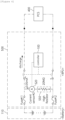
- FIG. 2 is a block diagram of a conventional battery state monitoring device.
- a device with a configuration as shown in FIG. 2 is conventionally used in order to monitor a battery state of an energy storage system.
- a first fuse is connected to the positive electrode of a series of batteries, and a second fuse is connected to the negative electrode of the battery.
- the other end of the first fuse is connected to the first main contactor, and the other end of the second fuse is connected to the second main contactor.
- the first main contactor is connected to the positive terminal of the DC link and the second main contactor is connected to the negative terminal of the DC link.
- a current sensor 510 is arranged between the main contactor and the DC link, and a rack BMS estimates a sum of battery cell voltages based on the current value measured by the current sensor 510.
- a case when a fuse is blown cannot be detected. It can be indirectly inferred that an error or problem has occurred in a fuse or any other components after recognizing that any current does not flow in response to a battery charge/discharge command. Thus, a normal maintenance manager cannot quickly and easily find out why charging and discharging does not work properly unless he/she is an experienced maintenance engineer.
- the present invention is proposed to solve this problem, and through the embodiments shown in FIGs. 3 to 6 , it is possible to simultaneously check the voltage information of the system and whether a fuse is blown.
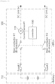
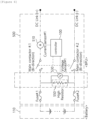
- FIG. 3 is a block diagram of an apparatus for detecting battery state according to an embodiment of the present invention.
- an apparatus for detecting battery state may comprise a first fuse connected to a positive terminal of a battery, a second fuse connected to a negative terminal of the battery, a high resistance resistor 550 connected to the first fuse and the second fuse and disposed in parallel with the battery, a sensor 520 configured to measure a current flowing through the high-resistance resistor, and a controller 100 configured to determine a system voltage and determine whether any of the fuses is blown from the measured current.
- the controller 100 may be a Rack BMS or may be included in the Rack BMS as a part of the Rack BMS.
- the senor 520 may be a current sensor positioned between the high resistance resistor and the first fuse and may be connected in series with the high resistance resistor.
- the sensor may be a current sensor positioned between the high resistance resistor and the second fuse and may be connected in series with the high resistance resistor.
- a high resistance resistor 550 may be positioned between a contact point of the first fuse and the first main contactor and a contact point of the second fuse and the second main contactor and may be arranged in parallel with the battery 110.
- a fuse is one of the main components of a battery protection device. It is a protection device that can be passively disconnected to protect the battery when a shortcircuit current occurs and is a one-time component that is essential for periodic replacement during use.
- a main contactor is an electrical switchgear, generally called as a magnetic contactor. The DC link must be closed to the ESS main circuits to enable charging and discharging of the battery.
- the resistance value of the high resistance resistor may be several megaohms (MQ).
- the high-resistance resistor is connected in parallel with the battery so that a small current of several mA flows through the high-resistance resistor and the small current is measured through the current sensor 520 connected in series with the high-resistance resistor.
- the controller may analyze the measured small current value and get information on a system voltage and information on whether fuse 1 or fuse 2 is blown. Accordingly, the current sensor 510 that used to be arranged in a conventional device may not necessarily be used.
- the apparatus for detecting battery state may use the element 550 having high resistance and let only a small current flow through the element, thereby monitoring the battery state without significantly affecting system-specific functions of battery charging and discharging.
- a battery protection apparatus 500 includes: a first fuse connected to a positive terminal of a battery; a second fuse connected to a negative terminal of the battery; a first main contactor configured to control a connection between the first fuse and the power conversion system; a second main contactor configured to control a connection between the second fuse and the power conversion system; a high resistance resistor 550 connected to the first fuse and the second fuse and disposed in parallel with the battery; a sensor 520 configured to measure a current flowing through the high-resistance resistor or a voltage applied to the high-resistance resistor; and a controller 100 configured to determine a system voltage and determine whether any of the fuses is blown from the measured current or measured voltage.
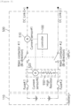
- FIG. 4 shows an example of determining system voltage information in an apparatus for detecting battery state according to an embodiment of the present invention.
- a high-resistance resistor is connected in parallel with the battery so that a small current of several mA flows through the high-resistance resistor, and the small current is measured through a current sensor 520 connected in series with the high-resistance resistor.
- the measured small current value can be analyzed by a controller 100 to determine the battery system voltage and whether a fuse therein is blown.
- FIG. 5 shows an example of checking whether a fuse is blown in the apparatus for detecting battery state according to an embodiment of the present invention.
- FIG. 5 shows an example case in which any current cannot be detected by a current sensor, that is, a current value with zero or close to zero is measured.
- the controller 100 may determine, from the current value measured by the current sensor, that one of the fuses (Fuse 1 or Fuse 2) is blown.
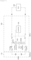
- FIG. 6 is a block diagram of an apparatus for detecting battery state according to another embodiment of the present invention.
- a high resistance resistor 550 is provided between a contact point of the first fuse and the first main contactor and a contact point between the second fuse and the second main contactor, and is connected in parallel with the battery 110.
- the resistance value of the high resistance resistor may be several megaohms (MQ).
- the apparatus for detecting battery state may comprise: a first fuse connected to a positive terminal of a battery; a second fuse connected to a negative terminal of the battery; a high resistance resistor 550 connected to the first fuse and the second fuse and disposed in parallel with the battery; a sensor 530 configured to measure a voltage applied to the high-resistance resistor; and a controller 100 configured to determine a system voltage and determine whether any of the fuses is blown from the measured voltage.
- the sensor may be a voltage sensor connected in parallel with the high resistance resistor to measure a voltage applied to the high resistance resistor.
- a voltage applied to the high resistance resistor may be measured by a voltage sensor 530 connected in parallel with the high resistance resistor.
- the voltage value applied to the high resistance resistor measured by the voltage sensor 530 when the fuses operate normally, may be the same as or similar to the system voltage value which is a sum of the voltage values of a plurality of batteries connected in series. In case a fuse is blown, the voltage applied to the high resistance resistor would be close to zero.
- the controller 100 may determine the measured voltage as the system voltage. On the othe hand, the controller 100 may determine that a fuse is blown when the voltage measured by the voltage sensor is close to zero.
- the embodiments of the present disclosure may be implemented as program instructions executable by a variety of computers and recorded on a computer readable medium.
- the computer readable medium may include a program instruction, a data file, a data structure, or a combination thereof.
- the program instructions recorded on the computer readable medium may be designed and configured specifically for the present disclosure or can be publicly known and available to those who are skilled in the field of computer software.
- Examples of the computer readable medium may include a hardware device such as ROM, RAM, and flash memory, which are specifically configured to store and execute the program instructions.
- Examples of the program instructions include machine codes made by, for example, a compiler, as well as high-level language codes executable by a computer, using an interpreter.
- the above exemplary hardware device can be configured to operate as at least one software module in order to perform the embodiments of the present disclosure, and vice versa.
Landscapes
- General Physics & Mathematics (AREA)
- Physics & Mathematics (AREA)
- Engineering & Computer Science (AREA)
- Chemical Kinetics & Catalysis (AREA)
- Chemical & Material Sciences (AREA)
- Electrochemistry (AREA)
- General Chemical & Material Sciences (AREA)
- Power Engineering (AREA)
- Manufacturing & Machinery (AREA)
- Charge And Discharge Circuits For Batteries Or The Like (AREA)
- Secondary Cells (AREA)
- Testing Electric Properties And Detecting Electric Faults (AREA)
- Protection Of Static Devices (AREA)
Applications Claiming Priority (2)
| Application Number | Priority Date | Filing Date | Title |
|---|---|---|---|
| KR1020210082830A KR102848533B1 (ko) | 2021-06-25 | 2021-06-25 | 배터리 상태 검출 장치 및 배터리 보호 장치 |
| PCT/KR2022/005726 WO2022270736A1 (fr) | 2021-06-25 | 2022-04-21 | Dispositif de détection d'état de batterie et dispositif de protection de batterie |
Publications (2)
| Publication Number | Publication Date |
|---|---|
| EP4174507A1 true EP4174507A1 (fr) | 2023-05-03 |
| EP4174507A4 EP4174507A4 (fr) | 2024-02-28 |
Family
ID=84545533
Family Applications (1)
| Application Number | Title | Priority Date | Filing Date |
|---|---|---|---|
| EP22828585.4A Pending EP4174507A4 (fr) | 2021-06-25 | 2022-04-21 | Dispositif de détection d'état de batterie et dispositif de protection de batterie |
Country Status (6)
| Country | Link |
|---|---|
| US (1) | US20230296679A1 (fr) |
| EP (1) | EP4174507A4 (fr) |
| JP (1) | JP7540795B2 (fr) |
| KR (1) | KR102848533B1 (fr) |
| CN (1) | CN219871725U (fr) |
| WO (1) | WO2022270736A1 (fr) |
Cited By (1)
| Publication number | Priority date | Publication date | Assignee | Title |
|---|---|---|---|---|
| CN117712521A (zh) * | 2023-06-28 | 2024-03-15 | 荣耀终端有限公司 | 新旧电池识别方法和设备 |
Families Citing this family (2)
| Publication number | Priority date | Publication date | Assignee | Title |
|---|---|---|---|---|
| KR102822937B1 (ko) | 2023-11-21 | 2025-06-23 | 주식회사 아진일렉텍 | 화재 대응 기능을 갖는 배전반 |
| KR102708087B1 (ko) | 2024-01-18 | 2024-09-20 | (주)우성엔텍 | 옥외용 외함 |
Family Cites Families (20)
| Publication number | Priority date | Publication date | Assignee | Title |
|---|---|---|---|---|
| US5343192A (en) * | 1992-09-10 | 1994-08-30 | At&T Bell Laboratories | Fuse or circuit breaker status indicator |
| US6531846B1 (en) * | 2001-05-03 | 2003-03-11 | National Semiconductor Corporation | Final discharge of a cell activated by a circuit that senses when a charging fault has occurred |
| US8058844B2 (en) * | 2006-05-31 | 2011-11-15 | Aeroflex Plainview, Inc. | Low-power battery system |
| JP4775415B2 (ja) | 2008-07-14 | 2011-09-21 | Tdk株式会社 | 電圧モニタ回路 |
| CN201274274Y (zh) * | 2008-09-25 | 2009-07-15 | 刘玉荣 | 车用保险丝监视器 |
| JP5381890B2 (ja) * | 2010-05-10 | 2014-01-08 | トヨタ自動車株式会社 | ハイブリッド車両におけるシステムリレーの診断装置およびその方法 |
| JP5670212B2 (ja) | 2011-01-28 | 2015-02-18 | 日立マクセル株式会社 | 電池ユニット |
| FI125404B (fi) * | 2011-04-21 | 2015-09-30 | Abb Oy | Järjestely sulakkeen valvomiseksi |
| JP6045984B2 (ja) | 2013-06-10 | 2016-12-14 | 古河電気工業株式会社 | 二次電池状態検知装置 |
| JP6510674B2 (ja) * | 2015-11-25 | 2019-05-08 | ヤマハ発動機株式会社 | リチウムイオン二次電池の保護回路及び電池パック |
| JP6755126B2 (ja) | 2016-06-02 | 2020-09-16 | Ntn株式会社 | 二次電池の劣化判定装置 |
| JP2018021880A (ja) * | 2016-08-05 | 2018-02-08 | 株式会社デンソーテン | 電圧監視装置および組電池監視システム |
| JP6718350B2 (ja) * | 2016-09-28 | 2020-07-08 | 株式会社ケーヒン | 電圧検出装置 |
| KR102051176B1 (ko) * | 2016-10-05 | 2019-12-02 | 주식회사 엘지화학 | 전압 분배를 이용한 퓨즈 진단 장치 및 방법 |
| JP6763313B2 (ja) | 2017-02-01 | 2020-09-30 | Tdk株式会社 | 蓄電池のヒューズ判定回路 |
| KR102324968B1 (ko) * | 2018-10-15 | 2021-11-11 | 주식회사 엘지에너지솔루션 | 퓨즈 연결성 진단 시스템 및 진단 방법, 퓨즈 연결성 진단 시스템을 포함하는 배터리 관리 시스템 |
| KR102841673B1 (ko) | 2019-07-10 | 2025-07-31 | 주식회사 엘지에너지솔루션 | 배터리 팩의 결함 검출 장치 및 방법 |
| KR102784889B1 (ko) * | 2019-12-06 | 2025-03-21 | 주식회사 엘지에너지솔루션 | 단로기를 이용한 전류 차단 장치 및 방법 |
| KR20210082830A (ko) | 2019-12-26 | 2021-07-06 | 주식회사 선익시스템 | 냉각 유닛 및 이를 포함하는 박막 증착 장치 |
| US20240204267A1 (en) * | 2022-12-14 | 2024-06-20 | Bae Systems Controls Inc. | Impedance balancing and continuity assurance for current limiting element in parallel path for prevention of thermal runaway propagation in battery system, packs and modules |
-
2021
- 2021-06-25 KR KR1020210082830A patent/KR102848533B1/ko active Active
-
2022
- 2022-04-21 US US18/016,233 patent/US20230296679A1/en active Pending
- 2022-04-21 EP EP22828585.4A patent/EP4174507A4/fr active Pending
- 2022-04-21 CN CN202290000182.0U patent/CN219871725U/zh active Active
- 2022-04-21 WO PCT/KR2022/005726 patent/WO2022270736A1/fr not_active Ceased
- 2022-04-21 JP JP2023503482A patent/JP7540795B2/ja active Active
Cited By (1)
| Publication number | Priority date | Publication date | Assignee | Title |
|---|---|---|---|---|
| CN117712521A (zh) * | 2023-06-28 | 2024-03-15 | 荣耀终端有限公司 | 新旧电池识别方法和设备 |
Also Published As
| Publication number | Publication date |
|---|---|
| JP2023534981A (ja) | 2023-08-15 |
| KR102848533B1 (ko) | 2025-08-20 |
| US20230296679A1 (en) | 2023-09-21 |
| EP4174507A4 (fr) | 2024-02-28 |
| KR20230000573A (ko) | 2023-01-03 |
| CN219871725U (zh) | 2023-10-20 |
| WO2022270736A1 (fr) | 2022-12-29 |
| JP7540795B2 (ja) | 2024-08-27 |
Similar Documents
| Publication | Publication Date | Title |
|---|---|---|
| EP3772657B1 (fr) | Dispositif et procédé pour effectuer une estimation de l'état de santé | |
| US9112247B2 (en) | Battery system | |
| US20230296679A1 (en) | Battery state detection device and battery protection device | |
| CN107863790A (zh) | 电源系统 | |
| CN113067042B (zh) | 一种储能装置及故障预测诊断方法 | |
| CN107887659A (zh) | 蓄电装置、蓄电系统、蓄电装置的状态判定方法 | |
| JP7679494B2 (ja) | 電池状態モニタリング装置及び方法、並びに電池保護装置 | |
| KR102658099B1 (ko) | 전압 평탄 구간을 갖는 배터리를 위한 배터리 관리 장치 및 이의 제어 방법 | |
| ES3058511T3 (en) | Battery control device for responding to loss of communication situation, and energy storage system comprising same | |
| KR20240043647A (ko) | 통신 이상 상황의 대응을 위한 배터리 제어 장치 및 이를 포함하는 에너지 저장 시스템 | |
| EP4414730B1 (fr) | Système de stockage d'énergie pour réagir à une situation de communication anormale et son procédé associé | |
| US20250279656A1 (en) | Battery Management Device Of Battery System To Which Battery Can Be Added, And Control Method Thereof | |
| EP4432512A1 (fr) | Dispositif de gestion de batterie pour batterie ayant une section de plateau de tension, et son procédé de commande | |
| CN111697659A (zh) | 一种电池管理电路 | |
| KR20240043646A (ko) | 통신 이상 상황의 대응을 위한 배터리 제어 장치 및 이를 포함하는 에너지 저장 시스템 | |
| CN118159857A (zh) | 用于通信丢失的电池控制装置以及包括该电池控制装置的储能系统 | |
| CN118140378A (zh) | 用于通信丢失的电池控制装置和包括其的能量存储系统 | |
| KR20260056413A (ko) | 밸런싱 회로의 상태 진단 장치 및 방법, 그리고 이를 포함하는 배터리 시스템 | |
| CN118414763A (zh) | 用于具有电压平台的电池的电池管理装置及其操作方法 | |
| KR20260045248A (ko) | 배터리 시스템 및 이의 운영 방법 | |
| CN111208369A (zh) | 核电厂直流系统短路电流的计算方法及装置 | |
| KR20260033134A (ko) | 전력 공급 유닛을 포함하는 배터리 시스템 및 이의 운영 방법 | |
| CN121970181A (zh) | 包括加热器的电池系统及其操作方法 | |
| CN118630859A (zh) | 一种电池簇并联抑制环流系统及方法、装置和存储介质 |
Legal Events
| Date | Code | Title | Description |
|---|---|---|---|
| STAA | Information on the status of an ep patent application or granted ep patent |
Free format text: STATUS: THE INTERNATIONAL PUBLICATION HAS BEEN MADE |
|
| PUAI | Public reference made under article 153(3) epc to a published international application that has entered the european phase |
Free format text: ORIGINAL CODE: 0009012 |
|
| STAA | Information on the status of an ep patent application or granted ep patent |
Free format text: STATUS: REQUEST FOR EXAMINATION WAS MADE |
|
| 17P | Request for examination filed |
Effective date: 20230130 |
|
| AK | Designated contracting states |
Kind code of ref document: A1 Designated state(s): AL AT BE BG CH CY CZ DE DK EE ES FI FR GB GR HR HU IE IS IT LI LT LU LV MC MK MT NL NO PL PT RO RS SE SI SK SM TR |
|
| A4 | Supplementary search report drawn up and despatched |
Effective date: 20240129 |
|
| RIC1 | Information provided on ipc code assigned before grant |
Ipc: H02H 7/18 20060101ALI20240123BHEP Ipc: H02H 3/087 20060101ALI20240123BHEP Ipc: H02H 3/04 20060101ALI20240123BHEP Ipc: H01M 10/42 20060101ALI20240123BHEP Ipc: H02J 7/00 20060101ALI20240123BHEP Ipc: G01R 31/367 20190101ALI20240123BHEP Ipc: G01R 31/396 20190101ALI20240123BHEP Ipc: G01R 31/382 20190101ALI20240123BHEP Ipc: G01R 31/56 20200101ALI20240123BHEP Ipc: G01R 31/52 20200101ALI20240123BHEP Ipc: G01R 31/392 20190101AFI20240123BHEP |
|
| DAV | Request for validation of the european patent (deleted) | ||
| DAX | Request for extension of the european patent (deleted) | ||
| STAA | Information on the status of an ep patent application or granted ep patent |
Free format text: STATUS: EXAMINATION IS IN PROGRESS |
|
| 17Q | First examination report despatched |
Effective date: 20250630 |
|
| REG | Reference to a national code |
Ref country code: DE Ref legal event code: R079 Free format text: PREVIOUS MAIN CLASS: G01R0031392000 Ipc: G01R0031520000 |
|
| GRAP | Despatch of communication of intention to grant a patent |
Free format text: ORIGINAL CODE: EPIDOSNIGR1 |
|
| STAA | Information on the status of an ep patent application or granted ep patent |
Free format text: STATUS: GRANT OF PATENT IS INTENDED |